1
Atmel AVR STK500
Communicating with a
Host PC and Temperature Sensor
User Manual
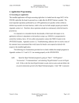
4. Application Programming
4.1 Writing an Application
The C programming language, not C++, is utilized to develop the applications that are uploaded
to the microcontroller used in this project. However, other languages, such as Assembly and
Pascal, can also be utilized as long as the code can be translated into a HEX or ROM file. The
purposes of these file types are further explained in section 4.2, Uploading an Application. The
following subsections provide programming examples for the ATmega8515L MCU.
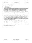
4.1.1 STK500 External Communication Protocol (USART)
The USART available on the STK500 is dependent on the MCU installed in one of the target
sockets [1], and it is used to communicate from the target MCU to various other devices [10]. In
this project, the target microcontroller is the ATmega8515L, which is installed in socket
SCKT3000D3 as shown in Figure 1.6. The USART interface of the STK500 consists of three
registers: the USART control and status register, the USART baud rate register, and the USART
data register (which is either 8-bit or 16-bit depending on the CPU of the target microcontroller)
[10]. The ATmega8515L is an 8-bit AVR (i.e. it has an 8-bit RISC CPU) so its USART data
register is an 8-bit register.
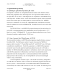
The keywords given to the USART registers by the CodeVisionAVR library for
ATmega8515L microcontrollers are UCSRA, UCSRB, UCSRC, UBRRH, and UBRRL where the
UCSRx keywords correspond to the high (A), middle (B), and low (C) sections of the USART
Control and Status Register and the UBRRx keywords correspond to the high (H) and low (L)
sections of the USART Baud Rate Register.
The USART data register is controlled by the specialized I/O functions provided in the
avr-libc library. Such input functions include getc and gets and such output functions include
putc, puts, and printf. These are the same functions available in the cstdio header of the
C Library (libc) [11], but they have been revised in the AVR C Library (avr-libc) for USART
communication with respect to AVR microcontrollers [10].
The required hardware setup to enable the use of the USART on the STK500 is given by
the instructions in section 2.2. Appendix section A.2.1 provides a sample program that can be
used to test USART communication between the board and its host. Sections 3.1 and 3.2 of this
Vincent A. Rosa
Florida Gulf Coast University
Spring 2009
Page 1 of 14
Atmel AVR STK500
Communicating with a
Host PC and Temperature Sensor
User Manual
document explain the necessary steps to take before applications development can begin on the
host PC. The following instructions describe steps to implement the application in Appendix
A.2.1 using the CodeVisionAVR IDE.
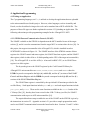
4.1.1.1
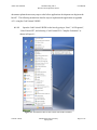
Open the CodeVisionAVR IDE on the host by going to “Start”, “All Programs”,
“CodeVisionAVR”, and selecting “CodeVisionAVR C Compiler Evaluation” as
shown in Figure 4.1.
Figure 4.1 Screenshot of how to start CodeVisionAVR Evaluation.
Vincent A. Rosa
Florida Gulf Coast University
Spring 2009
Page 2 of 14
Atmel AVR STK500
4.1.1.2
Communicating with a
Host PC and Temperature Sensor
User Manual
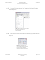
Go to the “File” menu and select “New” within the CodeVisionAVR window
shown in Figure 4.2.
Figure 4.2 Screenshot of how to create a
new source file or project in
CodeVisionAVR.
4.1.1.3
Select “Project” and click “OK” in the Create New File pop-up window shown in
Figure 4.3.
Figure 4.3 Screenshot of the
CodeVisionAVR pop-up selection
window to decide whether to
create a new source file or project.
Vincent A. Rosa
Florida Gulf Coast University
Spring 2009
Page 3 of 14
Atmel AVR STK500
4.1.1.4
Communicating with a
Host PC and Temperature Sensor
User Manual
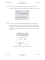
Select “Yes” in the “Confirm” pop-up window shown in Figure 4.4 to use a
wizard that will automatically generate certain AVR code based on the settings given.
Figure 4.4 Screenshot of the pop-up
window confirming whether or not to use
CodeWizardAVR to generate a new project.
4.1.1.5
Under the tab “Chip” within the CodeWizardAVR window, select the target
microcontroller (in this case, the ATmega8515L) from the “Chip” drop-down menu
and change the “Clock” setting to the appropriate System Oscillator Clock frequency
(fOSC) with respect to the target microcontroller (in this case, 3.6864 MHz) as shown
in Figure 4.5.
Figure 4.5 Screenshot of CodeWizardAVR Chip setup.
Vincent A. Rosa
Florida Gulf Coast University
Spring 2009
Page 4 of 14
Atmel AVR STK500
4.1.1.6
Communicating with a
Host PC and Temperature Sensor
User Manual
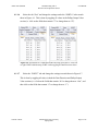
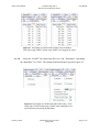
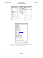
Select the tab “Port” and change the settings under the “PORTA” tab to match
those in Figure 4.6. This is done by toggling all values in the Pullup/Output Value
section (i.e. click on the fields that contain “T” to change them to “P”).
Figure 4.6 Screenshots of CodeWizardAVR Ports setup for PORTA. From left
to right: PORTA default setup; PORTA after toggling all Data Direction values.
4.1.1.7
Select the “PORTC” tab and change the settings to match those in Figure 4.7.
This is done by toggling all values in both the Data Direction and Pullup/Output
Value sections (i.e. click on the fields that contain “In” to change them to “Out”, and
then click on the fields that contain “0” to change them to “1”).
Vincent A. Rosa
Florida Gulf Coast University
Spring 2009
Page 5 of 14
Atmel AVR STK500
Communicating with a
Host PC and Temperature Sensor
User Manual
Figure 4.7 Screenshot of CodeWizardAVR Ports setup for PORTC.
From left to right: PORTC default setup; PORTC after toggling all values.
4.1.1.8
Select the “USART” tab, check both “Receiver” and “Transmitter”, and change
the “Baud Rate” to 115200. The settings should match those given by Figure 4.8.
Figure 4.8 Screenshot of CodeWizardAVR USART setup. From
left to right: USART default setup; USART after enabling Receiver
and Transmitter and setting the Baud Rate.
Vincent A. Rosa
Florida Gulf Coast University
Spring 2009
Page 6 of 14
Atmel AVR STK500
4.1.1.9
Communicating with a
Host PC and Temperature Sensor
User Manual
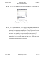
Go to the “File” menu and select “Generate, Save and Exit” as seen in Figure 4.9.
Figure 4.9 Screenshot of generating and
saving a program formed using the
CodeWizardAVR within CodeVisionAVR.
4.1.1.10
Go to your desired directory, say “C:\Documents and Settings\Administrator\My
Documents”, and create a new folder, say “STK500_TestProg” (Note: it is good
practice in CodeVisionAVR development to save all project files for a project within
the same designated folder). Go into this folder and give the C file a name, say
“stk500_test_prog” as shown by the first pop-up window within Figure 4.10. A
series of pop-up windows will appear for naming other files. Simply provide a name
for these files – they can be named with the same name as the C file, but they must be
given different extensions as shown in Figure 4.10.
Vincent A. Rosa
Florida Gulf Coast University
Spring 2009
Page 7 of 14
Atmel AVR STK500
Communicating with a
Host PC and Temperature Sensor
User Manual
Figure 4.10 From left to right, top to bottom: pop-up window to save the C source file (.c extension);
pop-up window to save the C project file (.prj extension); pop-up window to save the CodeVisionAVR
project file (.cwp extension).
4.1.1.11
Add the following code to the same areas shown in the program given in
Appendix section A.2.1 (these areas are relatively located towards the beginning and
end of the provided code).
#include <delay.h> // Contains “delay_ms()”
// Send the following message via USART communication
printf("USART Communication Test: Succeeded!!!\r\n");
// Check state of PORTA Pins
if(PINA != 0xFF)
Vincent A. Rosa
Florida Gulf Coast University
Spring 2009
Page 8 of 14
Atmel AVR STK500
Communicating with a
Host PC and Temperature Sensor
User Manual
{
// If a button is pressed (input pulled low), toggle bits on PORTC
PORTC = ~PORTC;
// Send the following message via USART communication
printf("Hello!\r\n");
// Delay so flashing LED's are visible
delay_ms(1000);
printf("Goodbye!\r\n");
PORTC = ~PORTC;
}
4.1.1.12
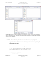
Got to the “File” menu and select “Save All” as seen in Figure 4.11 to save all
changes made to any of the project files.
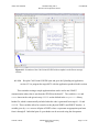
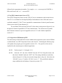
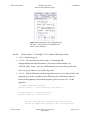
4.1.1.13
Go to the “Project” menu and select “Build All” as shown in Figure 4.11. Doing
this will build and compile all necessary files (including the HEX file used to
program the flash memory of the target MCU) from the code provided within the
target C file (in this case, from “stk500_test_prog.c”). It is possible for compilation
errors to occur during this process, but the results within the “Information” pop-up
window should look similar to those in Figure 4.12 if none appear. If any errors
exist, they will appear in the “Errors” message window shown in Figure 4.13. The
IDE will provide suggestions within this window on how to fix any incurred
compilation errors. Click “OK” within the Information pop-up window to proceed.
Vincent A. Rosa
Florida Gulf Coast University
Spring 2009
Page 9 of 14
Atmel AVR STK500
Communicating with a
Host PC and Temperature Sensor
User Manual
Figure 4.11 Screenshots within the CodeVisonAVR IDE. From left
to right: how to save all project files; how to build all project files.
Figure 4.12 Screenshot of the CodeVisionAVR “Information” popup window that appears after building project.
Vincent A. Rosa
Florida Gulf Coast University
Spring 2009
Page 10 of 14
Atmel AVR STK500
Communicating with a
Host PC and Temperature Sensor
User Manual
Figure 4.13 Screenshot of the CodeVisionAVR IDE with an emphasis on the Errors message
window.
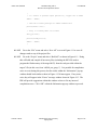
4.1.1.14
Keep the CodeVisionAVR IDE open and go to the Uploading an Application
section 4.2.2 to program the target MCU with the application produced in this section.
This concludes writing a sample application that can be used to test USART
communication where data is sent from the STK500 to the host PC. The variables PINA and
PORTC shown in the code given in step 4.1.1.11 are the defined in the mega8515.h library
header file, which is automatically included when the code is generated from steps 4.1.1.9 and
4.1.1.10. These variables allow for control over the physical PORTA and PORTC headers. A
variable given by PINx accesses all pins of PORTx where x represents an appropriate port letter
from A through E. Individual pins of a port header can be accessed using the dot operator
Vincent A. Rosa
Florida Gulf Coast University
Spring 2009
Page 11 of 14
Atmel AVR STK500
Communicating with a
Host PC and Temperature Sensor
User Manual
followed by the appropriate pin number. For example, PINB.0 accesses pin 0 of PORTB, i.e.
PB0 on the board, and PIND.7 accesses PD7.
4.1.2 myTWI Communication Protocol (I2C)
The myTWI Temperature Sensor uses the TWI (I2C bus) to communicate with external devices
where I2C is a serial data bus developed by Philips Semiconductors in the 1980s and is now a
worldwide standard [5]. The I2C bus is intended for communication of relatively small amounts
of data across relatively short distances [5].
The serial data (SDA) and serial clock (SCL) lines shown in the pinout in Figure 4.14 are
the physical elements responsible for I2C data communication. The software used to parallel
these hardware constructs is given in Appendix section A.2.2.1 and is further explained in
section 4.1.3.
4.1.3 DAQ with the STK500 and myTWI
The instructions provided within this section establish a data acquisition system with an STK500
evaluation board, a myTWI Temperature Sensor, and a host PC. Performing the following steps
will reproduce the program given in Appendix section A.2.2.1. The specifics of the code are
explained by the comments given within the application.
4.1.3.1
Perform steps 4.1.1.1 through 4.1.1.8
4.1.3.2
Select the “I2C” tab, select “PORTE” from the “I2C Port” drop-down menu, and
then check “Enabled” under the “LM75” tab. The settings should now match those
shown in Figure 4.14 (if they do not match, change them so they do). Notice how the
“SDA Bit” is set to “0” and the “SCL Bit” is set to “1”. This parallels the hardware
setup established in the Hardware Connectivity section 2.3.2.
Vincent A. Rosa
Florida Gulf Coast University
Spring 2009
Page 12 of 14
Atmel AVR STK500
Communicating with a
Host PC and Temperature Sensor
User Manual
Figure 4.14 Screenshot of the CodeWizardZVR
I2C setup. The I2C Port is set to PORTE and
LM75 is set as Enabled.
4.1.3.3
Perform steps 4.1.1.9 through 4.1.1.13 with the following revisions:
•
4.1.1.9 – Perform as given.
•
4.1.1.10 – The same directory can be used (“C:\Documents and
Settings\Administrator\My Documents”), but create a different folder, say
“STK500_DAQ_Temp”. Also, use a different name to save the files given by the
series of pop-up windows, say “stk500_daq_temp”.
•
4.1.1.11 – Add the following code from Appendix section A.2.2.1 instead of the code
originally given at this step (the areas the following code is added are relatively
located at the beginning and end of the program given in section A.2.2.1 of the
appendix):
// Standard Input/Output functions
#include <stdio.h> // Contains "printf()" and sprintf()"
#include <delay.h> // Contains "delay_ms()"
#include <stdlib.h> // Contains "abs()"
/*
* The "int lm75_temperature_10(unsigned char chip)" function
* returns the temperature in degrees C times 10 retrieved from
Vincent A. Rosa
Florida Gulf Coast University
Spring 2009
Page 13 of 14
Atmel AVR STK500
Communicating with a
Host PC and Temperature Sensor
User Manual
* the LM75 sensor with the address "chip".
*
* CAUTION: A 300ms delay must be present between two successive
*
calls to this function.
*/
// Get the temperature as an integer in degrees Celcius times 10
tempC_x10 = lm75_temperature_10(0);
PORTC = ~PORTC; // toggle LED values
// Send the temperature data via USART
// Divide by 10 to get the proper whole number temperature
// Append the the decimal value of the temperature to one place by
// using modulus 10
printf("%-i.%-u",tempC_x10/10,abs(tempC_x10%10));
PORTC = ~PORTC;
// Delay for DELAY_ms amount of time
delay_ms(DELAY_ms);
•
4.1.1.12 – Perform as given.
•
4.1.1.13 – Perform as given (in this case, however, all of the files compiled and built
are from the C file given by “stk500_daq_temp.c”).
•
4.1.1.14 – Perform as given.
This concludes creating the software that correlates with the DAQ system formed
between the STK500 PCB and myTWI Temperature Sensor. The CodeVisionAVR User Manual
[13] has more information on the functions available in the CodeVisionAVR LM75 library given
by the lm75.h header file, which is automatically included when the code is generated from
instruction 4.1.3.3.
Vincent A. Rosa
Florida Gulf Coast University
Spring 2009
Page 14 of 14