1
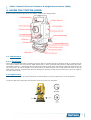
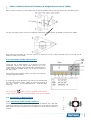
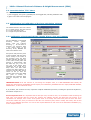
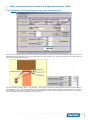
Manual
EDM
Version: 2012v1
Table of Contents
PREFACE......................................................................................................2
1. INTRODUCTION.......................................................................................3
2. SCHEMATIC SURVEY & CONFIGURATION CONTENTS..............................3
3. OPERATING PRINCIPLE...........................................................................3
4. USING THE TOPCON LASER.....................................................................4
4.1. Initialization...............................................................................................................4
4.1.1. Positioning...........................................................................................................4
4.1.2 Spirit Level...........................................................................................................4
4.1.3 Powering up the Topcon Laser.................................................................................5
4.2. Performing a Measurement...........................................................................................5
4.2.1 Positioning the (Prism) Reflector..............................................................................5
4.2.2 Directing the laser to the prism reflector..................................................................6
4.2.3 Actual Laser Measurement......................................................................................6
5. SOFTWARE..............................................................................................6
5.1. Installation and startup................................................................................................6
5.2. LaserCalculation “File”-Menu.........................................................................................7
5.3. Initialization and calibration of the laser calculation software............................................7
5.3.1 Calibration of horizontal throws: javelin, discus, shot put, hammer..................................7
5.3.2 Calibration of horizontal jumps: long jump and triple jump.........................................8
5.3.3 Calibration of vertical jumps: high jump and pole vault..............................................9
5.4. Performing the actual measurements.............................................................................9
5.5. Display and printing the loggings..................................................................................9
APPENDIX 1: LASER SOFTWARE SERIAL OUT PROTOCOL..........................10
www.timetronics.be
TimeTronics NV
Lammerdries-Oost 23B
B-2250, Belgium
Tel +32 (0)14 23 19 11
Fax +32 (0)14 23 20 24
VAT BE0440 224 404
HR Turnhout 64540
KBC Bank 414-4191871-52
SWIFT : KREDBE22
IBAN : BE64 4144 1918 7152
2012v1 Manual Electronic Distance & Height Measurement (EDM)
PREFACE
Welcome to the "Electronic Distance & Height Measurement (EDM) " user
manual.
May we recommend you to gently leaf through the entire manual first, just to have an initial idea of how the book is
structured. As we cannot possibly explain all details simultaneously, this might help you a bit in understanding and tracing
things back. Of course, the table of contents will also help you in doing so.
Please note that all pictures are examples, the delivered version can be different than shown in this manual please inform
yourself before purchase.
If you, after reading this document, have any further question regarding the operation or service of this or any other
TimeTronics equipment, please contact your local distributor or TimeTronics directly, by email: [email protected], or call
us at +32 (0) 14 23 19 11
Please also contact us if you have any remarks or advise regarding this user manual: [email protected].
Good luck with your Electronic Distance & Height Measurement (EDM) and thank you for your confidence in the
TimeTronics products and services.
The editors.
© Copyright 2012 TimeTronics. All rights reserved.
TimeTronics
Lammerdries 23b
B-2250 Olen
Belgium
Tel.: +32 (0) 14 23 19 11
Disclaimer
Under no circumstances shall TimeTronics be liable for any loss, damage or expense suffered or incurred with respect to
any defective product. In no event shall TimeTronics be liable for any incidental or consequential damages that you may
suffer directly or indirectly from use of any product. Windows, Windows XP and Windows VISTA are registered trademarks
of Microsoft Corporation.
2
2012v1 Manual Electronic Distance & Height Measurement (EDM)
1. INTRODUCTION
The Laser distance measuring system can be used in athletics for javelin throwing, discus throwing, hammer throwing,
shot put, long jump, triple jump, and pole vault.
The laser equipment does the distance and angle measurement. The real result in athletics is obtained by:
a) A PC windows program, see chapter 5
b) The Field Terminal in combination with the AthleticsManager program.
Field Terminal and AthleticsManager are described in other manuals.
2. SCHEMATIC SURVEY & CONFIGURATION CONTENTS
Please find subsequent elements in your configuration:
- Laser distance measurement instrument (with build-in battery) on tripod, +
carrying case + cable.
- Prism reflector on small pole.
- Mobile caddy on wheels with build-in portable PC with Laser Calculation
(LCxx) software
The Topcon laser distance measuring system is power supplied via the build-in battery
pack. The portable pc can work a limited time on its internal battery, but long
operation (e.g. a full day), can only be done if the 220vac/110Vac power adapter is
used.
3. OPERATING PRINCIPLE
EXAMPLE: SHOT PUT (also see schematic representation)
Before the start of the event, the Topcon laser first measures:
- Distance ‘A’ (= distance between the centre point of the throwing sector and the position of the Topcon)
- Angle ‘a’ (= the relative angle (direction))
After each athlete’s attempt, the distance between the point of impact (= point of positioning the reflector) and the Topcon
laser (=’B’) and the relative angle ‘b’ are measured by means of the laser system.
Now the angle ‘C’ (= b minus a) can be calculated.
Through the principle of trigonometry, the instrument automatically calculates the distance between the centre point of
the throwing circle and the point of impact (D).
Subsequently, 1/2 diameter of the throwing circle is subtracted from this distance. That way we obtain the final result (R).
The distance, which is subtracted from ‘D’, is a variable in the software and is dependent on the athletic event in question.
3
2012v1 Manual Electronic Distance & Height Measurement (EDM)
4. USING THE TOPCON LASER
Further in this manual we will refer to the numbers visible on the drawing below:
4.1. Initialization
4.1.1. Positioning
Find a safe and practical location to position the Topcon laser at a random side of the throwing sector or jumping area. Be
sure that you have a clear view over the TOTAL landing area, in other words that there will be no obstructions (like poles,
scoreboards, persons,...) between the laser and the future landing points which could disturb a practical measurement. Do
not put the laser ‘as close as possible’ to the landing area, for safety reasons, but it is also faster and easier to put the
laser system minimum 10 meters away from the landing area, because you will then have less work to focus the eyepiece
for each jump or throw.
4.1.2 Spirit Level
Please make sure that the (6) circular spirit level on the base plate (10) of the Topcon laser is in correct position.
To tune the spirit level, please first use the three screws (9) on the very same base.
4
2012v1 Manual Electronic Distance & Height Measurement (EDM)
After you have tuned the (6) circular spirit level as good as possible, finetune the laser spirit level in the following way:
Use the (9) leveling screws “A” and “C” to adjust the plate level (12) so that the ‘air bubble’ is exactly in the middle.
Now rotate the instrument 90 ° and use only the (9) leveling screw “B” to adjust the plate level (12) so that the ‘air
bubble’ is exactly in the middle.
4.1.3 Powering up the Topcon Laser
Check that the on board battery (2) is placed on the laser
instrument. Connect the Topcon serial connector (8) to the
mobile caddy by means of the special cable, supplied with the
system. Press the ‘POWER’ button (26) on the front panel of
the Topcon laser:
On the Topcon laser’s display window, you will see the welcome
message “Topcon GTS-220”.
If not already so, press the button (29) until you see the following
“Angular measurement mode”, visible on the first three lines of
the LCD display (V=vert.angle/HR=Horiz. angle/SD=slope
distance):
Do not use the
button (30) for “coordinate measurement
mode”, as this will give you no result calculation in the current software.
4.2. Performing a Measurement
4.2.1 Positioning the (Prism) Reflector
Screw the prism reflector onto the little pole as low as possible. For a first test,
position the reflector on the center of the throwing circle or somewhere in the field.
Make always sure that the spirit level on the reflector is correct when you place it in
position.
5
2012v1 Manual Electronic Distance & Height Measurement (EDM)
4.2.2 Directing the laser to the prism reflector
We first unlock the laser direction by means of screws (4) and (14). We
make a raw estimation of the direction by looking through the small
telescopic collimator (17) on top of the Topcon laser. Try to direct the
triangle within this tube approximately ten centimeters above the prism
reflector in the field.
Then lock the Topcon laser with BOTH screws (4) and (14). We now look
through the eyepiece (15) of the Topcon laser and try to track down the
reflector in the heart of the eye. You can focus the eye by turning the ring
(16) around the eye.
When the eye of the Topcon laser is pointed to the prism reflector, you
can optionally hear a buzzing sound.
We now fine tune the laser direction by means of the controls (5) and
(13).
4.2.3 Actual Laser Measurement
You
perform
the
actual
laser
measurement
by
pressing
the
“ESC”
button
(27).
This button will perform the laser measurement, but will NOT YET send the measurement data towards the computer.
After the measurement you will see the text “>REC ? [YES] [NO]” on line 4 of the LCD display, and you can send the data
to the computer by means of the [YES] action = the “F3” button (23).
Example: On the display, you could see the HR (horizontal angle 28°30’50”), V
(vertical angle 90°56’25”) and SD (Slope Distance 32,003m):
You can now unlock the Topcon laser again by means of screws (4) and (14) and put it out of position (which will stop the
optional buzzer sound).
The operator (or official) with the prism mirror can now be informed that the measurement is completed, so that he can
move away from the throwing area, to allow the next athlete to compete.
The PC software will record the transmitted data, and calculate and display the required distance or height result,
depending on the selected athletic event.
5. SOFTWARE
5.1. Installation and startup
Copy the “LCxx” software folder (for example LC06 where xx is the latest version
number 06) from the TimeTronics cd to your harddisk “C” of your computer.
Start now the (application) ‘LCxx.EXE’ (=LaserCalculation program), which you have
placed on your harddisk, by double clicking its icon. The first time that you start the
program, it will ask you for a suitable data file. Just press the “NEW” button, and give a
name and location for the new datafile, for example “LC datafile”. You now see the
background screen of the program, with the ‘TimeTronics’ logo.
6
2012v1 Manual Electronic Distance & Height Measurement (EDM)
5.2. LaserCalculation “File”-Menu
The “File” menu has two items:
1) List of loggings; this gives a (printable) list of all logged data, including calibration data.
2) Quit: to be used to end the program.
5.3. Initialization and calibration of the laser calculation software
The “Measurements” menu has 3 items:
5.3.1. Javelin, discus, shot put, hammer
5.3.2. Long and Triple Jump
5.3.3. High Jump and Pole Vault
5.3.1 Calibration of horizontal throws: javelin, discus, shot put, hammer
For the calibration of horizontal
throwing
events
(javelin,
discus, shot put, hammer
throwing,...) , we will have to
measure one reference point
( the ‘centre point’ of the
throwing circle) BEFORE the
start of the athletic event.
One person will place the point
of the small bar with the prism
mirror exactly in the centre of
the throwing circle, the laser
operator will align the laser eye
to the centre of the prism and
perform a measurement with
the “ESC” key (27) + the “F3”
key (23) of the Topcon laser
equipment. The pc will give a
beep when the laser data
(angles and slope distance) is
received, and this data will be
shown on the pc. Now the
operator has to press the “NEW
Ref.
point
1”
button,
to
memorize this reference point
into the computer, for THIS
EVENT.
IMPORTANT NOTE: From this moment on, and during the complete event, it is VERY IMPORTANT that nobody will
disturb the measurements by MOVING the laser tripod (even millimeters), ROTATING the laser tripod, APPLYING SHOCKS,
POWER failure, or other abnormal events.
If, by accident, this would be the case, repeat the complete initialization procedure, including the spirit level adjustment ,
described in chapter 4.1.2.
Second important note: It is important that the shot put circle, the discus circle, etc are EXACTLY made according the
IAAF rules, more specific with the correct size, because the software will take the IAAF sizes into account in its
calculations. For example, if the ‘centre’ of the javelin sector is not exactly 8.00 meter away from the inner side of the
curved zero marker line, then you will have to find the ‘new’ reference point, which is exactly 8.00 meter, and use this
point for your calibration procedure. You can see the required distance for each event in the data field “LaserOffset (m)”,
on the computer screen.
7
2012v1 Manual Electronic Distance & Height Measurement (EDM)
5.3.2 Calibration of horizontal jumps: long jump and triple jump
For long jump and triple jump events we do not use one reference point but TWO reference points, exactly between the
springboard and the plasticine. These two points define the ‘zero’ distance line, which the jumper may not cross with his
foot. See schematic representation:
First we measure reference point 1 with the laser . After having conveyed the data towards computer, press the button
‘NEW Ref.Point 1’ on your computer window. Then we identically measure reference point 2 with the laser and then click
the ‘New Ref.point 2’ button. The date and time of both reference points will be memorized and shown on your computer
screen, but also logged into the data file (see chapter 5.5).
8
2012v1 Manual Electronic Distance & Height Measurement (EDM)
5.3.3 Calibration of vertical jumps: high jump and pole vault
For high jump or pole vault, we do not measure special reference points on the track. For these events, we first put the
horizontal bar at an appropriate starting height, we measure this height with a “classic” method, and enter this calibration
height into the program, AFTER we have measured this height with the laser!
Press therefore the “Calibration” button, and the software will then ask for the calibration height.
For this laser measurement, we do not point the laser to the prism mirror, because it is practically impossible to fix this
(rather large) mirror to the horizontal bar, especially DURING the event.... We use a special reflective tape, which can be
easily fixed in the middle the horizontal bar.
You could also place extra two reflective tapes to the left and right side of the bar, to verify with the laser system that the
bar is placed HORIZONTALLY, which is important to have a fair event for all athletes.
Note 1:
the software makes it possible to use ONE laser system for TWO (pole vault) pits at the same time, at least if they are
located next to each other. The reason for this functionality is that the period between two successive heights can be long,
so that there is sufficient time for the laser operator to measure both horizontal bars. Of course, for this double
measurement you will have to calibrate BOTH pole vault stands SEPARATELY, using the separate buttons.
Note 2:
It is NOT required to move the horizontal pole vault bar each laser measurement to the ‘zero depth’ position (above the
pole vault pit), because the software will take all dimensions into account in its calculation, including this ‘depth’.
5.4. Performing the actual measurements
One person will place the point of the small bar with the prism mirror exactly on the impact point of the implement, the
laser operator will align the laser eye to the center of the prism and perform a measurement with the “ESC” key (27) +
the “F3” key (23) of the Topcon laser equipment. The pc will give a beep when the laser data (angles and slope distance)
is received, and the measured result will be shown on the screen, and logged into the database. This result is also serially
transmitted by the serial port of the pc, to be captured by other computer systems (optional).
5.5. Display and printing the loggings
To display and/or print the list of loggings, first stop the serial communication and close the “measurement window” by
clicking in the “X” button on the top-right corner. You will again see the “background” window with the TimeTronics logo.
Now select the second item from the “File” menu; List of loggings.
From this window you can investigate all user actions, calibration data, and measurement results.
On the bottom of the screen you can find the “Print” button.
-----------------------------------------------
9
2012v1 Manual Electronic Distance & Height Measurement (EDM)
APPENDIX 1: LASER SOFTWARE SERIAL OUT PROTOCOL
The Laser distance measuring system can live output the results by means of a RS232 serial out connector.
Use a standard “MacFinish” type 5 pins male connector to tap this output line, where you use the following connections:
Pin 2 = Ground
Pin 4 = Serial data out, RS232, 1200 baud, 7 databits, Even parity, 1 stop bit
These serial settings are FIXED, and exactly the same as the serial settings of the (TOPCON) laser system, because there
is ONLY 1 serial port used in the (portable) pc that does the calculations. For this (COM1) serial port of the pc, the serial
input is used for the laser, and the serial output is used for outputting the results to an external computer for further
processing or displaying the results on TV or a scoreboard.
The serial data out will be always 10 characters, for each result record, in the following format:
“Header”+”DATA block”+”Footer”
where
“Header”= one character= HEXADECIMAL 02
”DATA block” = 8 characters
”Footer”= one character=HEXADECIMAL 03
The ”DATA block” can be one of the following types of result:
1) Real result, measured with the laser system, expressed in "m" (meter):
or in detail “hex 20” + the numeric result in ascii format
“xxx.xx”
“xxx.xx” + “hex 20”.
2) Good attempt, or the “OK” button in the software or the “F1” function key:
“o“
3) Bad attempt, or the “Failed” button in the software or the “F2” function key:
“x“
4) No attempt, or the “No attempt” button in the software or the “F3” function key:
“-“
5) Abandon, or the “Abandon” button in the software or the “F4” function key:
“a“
6) No result, or the “No result” button in the software or the “F5” function key:
““
10
2012v1 Manual Electronic Distance & Height Measurement (EDM)
© Copyright 2012 TimeTronics. All rights reserved.
TimeTronics
Lammerdries 23b
B-2250 Olen
Belgium
Tel. : +32 (0) 14 23 19 11
Fax : +32 (0) 14 23 20 24
11


![English [2012v1]](http://vs1.manualzilla.com/store/data/005947215_1-83afe423bc1815c8427a220bc0eb1bc7-150x150.png)

![English [2012v1]](http://vs1.manualzilla.com/store/data/005666127_1-015c2c1b906ab908850f1f1f8721a849-150x150.png)
![English [2012v1]](http://vs1.manualzilla.com/store/data/005770981_1-8c196de42073f8db3e58cd387e9490be-150x150.png)
![English [2012v1]](http://vs1.manualzilla.com/store/data/005994732_1-5b50c16b769d7d14a751f578cdbfd574-150x150.png)

![English [2014v1]](http://vs1.manualzilla.com/store/data/005775879_1-a83e57144a66539570f80a48a6e80397-150x150.png)
![English [2015v1]](http://vs1.manualzilla.com/store/data/005829431_1-1fdc30543d444fb0915a40c3aab945a8-150x150.png)