1
KVM Switch CAT-32 IP
with KVM over IP module slot
User Manual
English
KVM Switch CAT-32 IP: No. 39631
KVM Switch Module for LCD Terminals: No. 39635
www.lindy.com
Tested to comply
with FCC Standards
For Commercial Use Only
© LINDY ELECTRONICS LIMITED & LINDY-ELEKTRONIK GMBH – 3rd EDITION (AUG 2014)
Section 1
Introducing the CAT-32 IP
1.1. Introduction
Thank you for purchasing this LINDY KVM Switch. Please read this manual carefully to fully
understand the functions and features that the switch offers.
Using the LINDY KVM Switch CAT-32 IP a system administrator can access and control several
computers from one compact and high density KVM control center with 32 server ports
occupying only 1U height within a 19” rack.
The modular version KVM Switch CAT-32 IP has the same features but it does not offer the
front panel display and allows the KVM switch to fit into the back of the LINDY LCD Terminal
PRO Dual Rail and Classic Single Rail.
Both KVM Switch CAT-32 allow you to install an optional KVM over IP Remote Access Module
into a slot located in the back of the KVM switch. With this module installed the administrator
can access any of the computers connected to the KVM Switch from any remote computer on a
local LAN or via the Internet using a web browser.
The LINDY KVM Switch CAT-32 allows direct access to up to 32 computers using a single KVM
(Keyboard, Video, and Mouse) either from a local or remote console. To administrate a larger
number of computers multiple switches can be used. They can be either equipped with a KVM
over IP module each or they can easily be daisy chained with an IP module located in the
master KVM switch only.
A dedicated daisy chain port allows a total number of 8 KVM Switches to be connected (daisy
chained) together to control up to 256 computers. Using this daisy chain port method ensures
that none of the computer ports are lost due to cascading. Using IP modules in each KVM
Switch allows users to access even more than 256 computers and provides individual
simultaneous access to every KVM switch with an IP module and by several users.
The CAT-32 KVM Switch supports two methods of switching between the connected
computers: by using keyboard hotkeys or via an OSD (On Screen Display).
The KVM Switch CAT-32 IP has a single user password protection with auto logout security.
The security features for the KVM over IP user are based on SSL and additionally KVM
encrypted connections with a further level of password login.
The LINDY KVM Switch CAT-32 supports USB as well as PS/2 style keyboard and mouse from
the local console.
Technological progress
The KVM Switch and especially the KVM over IP Module and its software are subject to
technological progress. The products are continuously upgraded accordingly. Therefore minor
changes compared to the descriptions in this manual may be found
2
Section 1
Introducing the CAT-32 IP
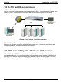
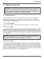
1.2. CAT-32 with IP access module
KVM over IP technology allows a simple web browser interface to be used to access the switch
and the connected computers via a local area network (LAN) or, when connected to a wide area
network (WAN), allows access to the switch and the connected computers from almost
anywhere in the world.
IP Network
KVM
Switch
Local Console
Remote Access
Multiple Servers
Remote & local control of multiple computers
The CAT-32 with IP module provides a non-intrusive solution for remote access and control
because the software runs on its embedded processors only, so there’s no interference with
computer operation, or impact on network performance.
1.3. KVM compatibility with other series KVM switches
The KVM Switch CAT-32 is compatible with most other brands of KVM switches using a port
cascaded installation. To prevent any hotkey conflicts, please ensure that the KVM hotkeys of
the other KVM switches used are not the same as those used on the KVM Switch CAT-32 IP.
The KVM hotkeys of the KVM Switch CAT-32 IP can be configured via the OSD.
3
Section 1
Introducing the CAT-32 IP
1.4. Product Features
32 UTP Cat.5/6 server ports in a narrow 1U, 19” rack mount design
Dual console operation option: Local console plus a remote console access slot for optional
KVM over IP module
Local console connected by VGA and USB as well as PS/2 style keyboard and mouse
Compatible with all commonly used operating systems
Supports USB as well as PS/2 computers using the appropriate Computer Modules
Hot Plug Support allows computers to be added or removed for maintenance without
powering down the KVM switch or the computers
High Quality Video – Supports display resolutions of up to 1920 x 1200 at the local console
Supports up to 1280 x 1024 at the IP console, 1600 x 1200 in virtual desktop mode
No Software Required - easy computer selection via the On Screen Display Menu or
Keyboard Hot Keys
Each computer can be individually named in the On Screen Display Menu
Password log in protection for access to the KVM Switch, auto log out option
SSL security and additional password protection for IP access users
Auto Scan Mode with an adjustable scan time from 5~104 seconds for monitoring computers
Keyboard status automatically restored when switching between computers
Front panel LED indicators for easy status monitoring (Stand-alone version No.39631 only)
2 Digit LED display indicates the cascaded KVM Switch number (No.39631 only)
32x RJ45 ports for UTP cables to connect to the servers with up to 100m distance each
Separate built-in daisy chain port prevents the loss of any computer port when cascading
1.5. Package Contents
No. 39631, (1) KVM Switch CAT-32
(2) Firmware upgrade cable
(3) Daisy Chain cable
(4) Power Adapter
(5) 19" Rack Mount Kit
(6) CD containing English full user manual
(7) Printed Quick User Guides (English, French, German, Italian)
No. 39635, (1) KVM Switch CAT-32 Module for the back of the LCD terminal
(2) LCD Terminal mounting brackets (x2) and screws (x4)
(3) Printed Quick User Guides (English, French, German, Italian)
4
Section 1
Introducing the CAT-32 IP
1.6. Optional Cables and Accessories
The remote access KVM over IP module can be installed at any time. To install it into the KVM
Switch CAT-32 ensure all connected computers are switched off or disconnected and the power
supply is unplugged. Open the slot on the back of the KVM Switch and slide the module into the
slot.
KVM over IP module for Stand-alone KVM Switch No. 39631: No. 39636
KVM over IP module for modular KVM Switch No. 39635: No. 39432
The local monitor, mouse and keyboard is connected using their standard cables.
To connect each individual computer to the switch, Cat.5/6 computer modules are required. For
USB or PS/2 computers different modules have to be used as listed below:
For PS/2 computers: Cat.5/6 Computer module PS/2 & VGA, LINDY No. 39633
For USB computers: Cat.5/6 Computer module USB & VGA, LINDY No. 39634
A Cat.5e or 6 UTP cable of appropriate length (max. 100m) is required to connect the KVM
Switch to the computer modules. These cables are available from LINDY in several different
colors and lengths from 0.3m up to 100m. We don’t recommend using shielded FTP/STP
cables. Please find a small overview below:
UTP Cat.5e
0.5m 1m
2m
3m
5m
7.5m 10m 15m 20m 30m
45961 45962 45963 45964 45965 45966 45967 45968 45969 45970
40m 50m 60m 70m 80m 90m 100m
45971 45972 44733 45974 44735 44736 45977
UTP Cat.6
0.5m 1m
2m
3m
5m
7.5m 10m 15m 20m 30m
45771 45772 45773 45774 45775 45776 45777 45778 45779 45780
Daisy Chain Cable
A short Daisy Chain Cable is included to cascade KVM switches with each other. Longer cables
are available from LINDY: No. 39637 (1m) and No.39638 (2m).
To reach even longer distances several 2m cables can be chained together.
5
Section 2
Hardware Installation
2.1. Hardware Installation Guide
Before you start please verify that all parts are included according to the package contents
listed previously.
Please prepare the required amount of KVM Computer Access Modules and UTP cables to
connect to your computers/servers.
Stand-alone KVM Switch CAT-32 No.39631: If you want to install the KVM Switch in a 19”
server rack please attach the enclosed 19” rack mount brackets using the screws provided.
In addition to the computers/servers to be connected, you will need a keyboard, monitor and
mouse to use as a local console.
Modular KVM Switch CAT-32 No.39635: To assemble the KVM Switch CAT-32 to the back of
the LCD Terminal, install the two brackets to the KVM Switch using the supplied screws. Then
attach the KVM Switch to the back of the LCD Terminal so that the Centronics connectors
properly fits. The KVM Switch uses the power supply of the LCD terminal and feeds the voltage
through to the LCD terminal. Tighten the screws properly.
If you intend to install the optional KVM over IP module then please install it into the
module slot before you connect the servers and the power supply to the KVM Switch.
You may also wish to attach one of the information labels supplied with the KVM over IP
module to the back (or the front) of the KVM Switch / LCD Terminal so that you can easily
locate the IP modules MAC address.
Cascading / Daisy chaining of multiple KVM Switches
You can integrate up to 8 KVM Switches in one KVM daisy chained installation with up to a
maximum of 256 attached computers.
To connect an additional slave KVM Switch to the MASTER (or previous) KVM switch use a
standard daisy chain KVM cable as mentioned above. Connect it to the Daisy Chain OUT port
of the MASTER KVM switch and to the Daisy Chain IN port of the first slave KVM switch. To
connect the second slave KVM switch connect the Daisy Chain OUT port of the first slave
KVM switch to the Daisy Chain IN port of the second slave KVM switch. Repeat this step up to
a maximum of 8 KVM switches with a maximum of 256 servers.
1. Switch off all the computers to be attached.
2. Connect the keyboard, monitor and mouse directly to the ports of the LINDY KVM
Switch labelled Local Console.
3. Now connect the servers and computers to the ports labelled 1 to 32 using UTP
cable of appropriate length and an appropriate Computer Access Module.
4. Attach the power supply to the KVM Switch. Switch on your monitor.
To set up and configure the KVM over IP remote access module, please refer to the user
manual.
You may also refer to the printed Quick Start Guide supplied with the KVM over IP
module.
6
Troubleshootin
g
3.1. KVM Switch Operation
Please Note: Your monitor will only display one computer signal at any one time. All
keyboard and mouse commands are sent to this computer as shown on the monitor.
When the computer connected to the currently selected port is not switched on,
or is in sleep mode, the monitor will not display any signal.
3.1.1. Password Security
The KVM Switch CAT-32 IP has a single user password protection with auto logout security.
The additional security features for the KVM over IP user are based on SSL and additionally
KVM encrypted connections with a further level of password login. Details can be found in the
user manual of the KVM over IP module.
3.1.2. Hot Plug Support
The KVM Switch supports a “Hot Plug” function for easy addition or removal of computers.
PS/2 computer modules
If a computer is already running and its PS/2 interface has already been initialized, it is not
required to turn off the computer. Simply hot-plug the PS/2 computer module to the computer.
Always connect the PS/2 mouse port first to allow the correct initialization sequence! If the PS/2
ports of the computer haven't been initialized during boot up it may however be necessary to turn
off the computer before connecting the PS/2 computer module so the OS can initialize the PS/2
ports during boot up.
Please note: Some Operating Systems including certain Unix versions may be unable to
support the “Hot Plugging” function. If you “Hot Plug” when using this kind of O.S., it may
cause unpredictable operation and may even shut down the computer.
USB computer modules
The USB and VGA interface is hot pluggable on most OS and computer systems. Therefore you
may connect and disconnect USB computer modules at any time. Connect the computer modules
to the KVM Switch using UTP Cat.5e/6 cables of appropriate length. In most cases standard patch
cable UTP Cat.5e or 6 can be used without any problems. For best video results at very large
distances and high resolutions UTP Cat.6 solid core cable may be used to improve video quality
and distance. Shielded FTP/STP is not recommended. After the computers are connected and
powered up you can access them from the KVM Switch CAT-32.
7
Troubleshooting
3.1.3. Computer / Port Selection
You can select the computer you want to access in one of two different ways:
Keyboard hotkey selection
On screen display menu selection
3.1.4. Illuminated front display, Stand-alone KVM Switch CAT32 only!
The front display has a two digit display to show the number of the KVM switch in the cascade:
01: Master, 02: first slave, 03: second slave. In addition one LED per Port shows the status of
the connected port:
GREEN (solid): the computer on this port is powered (switched on or soft off with 5V active)
GREEN (blinking/flickering): this port is currently selected, displayed on the monitor, and
keyboard/mouse commands are sent to the computer attached to this port.
Dark: No computer connected or computer not powered up / no 5V signal active
One red Power LED near the bank display shows if the KVM Switch is powered up.
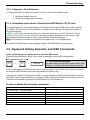
3.2. Keyboard Hotkey Selection and OSD Commands
Press the following key combination to enter the OSD menu:
(Factory Default Hotkey is Scroll Lock; it can be changed via the OSD configuration)
Within 2 seconds
Scroll
Lock
+
Scroll
Lock
+
= On Screen Display Menu
In most cases you can select ports via the OSD
display or via the keyboard hotkey commands
Space bar
With a small delay the OSD pops up on your monitor and you can use the cursor keys to navigate
through the OSD and select functions by pressing the Return key.
Alternatively, instead of waiting for the OSD, you can press the initial Scroll Lock hotkey twice and
add further direct keyboard hotkey commands within 2 seconds after the initial hotkey to switch
computer ports directly or change the KVM Switch CAT-32 settings etc.
Further available direct hotkey commands:
Command
↑ (Cursor up) / ↓ (Cursor down)
Action
Select next higher/lower port
Page Up / Page Down
H + { Scroll / Num / Caps / ESC / F12 }
0101 ………… 0832
T
Z
S
Select next higher/lower bank/KVM switch
Change primary hotkey
Bank + port number direct selection
OSD port info screen on/off
Remote console on/disabled
Start Autoscan
8
Troubleshooting
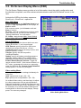
3.3. On Screen Display Menu (OSD)
The On Screen Display menu provides a lot of information about the switch configuration and
the attached computers, and offers advanced administration and full KVM Switch control to the
user.
Activate the OSD by the hotkey sequence:
Scroll Lock + Scroll Lock + space bar
Main OSD Menu
Select computer/port: use Up/Down Arrow key to
navigate, Page Up/Page Down to scroll page, hit
Enter to select.
Edit computer name: just hit Insert to edit and
Enter to confirm.
F2: Save - Save all modifications you have made.
When pressing F2, you will see the message-"Saving parameters" for confirmation.
F1: Setup - rotate through Main/ Video Setting/
Setup/ Status OSD menu pages
Main OSD Menu
Setup OSD Menu
Auto logout: specify the timeout before an autologout (00~99 min, +1 min) is performed
OSD Timeout: specify timeout for OSD menu
remaining on screen (00~99 sec, +5 sec)
AutoScan period: Specify the delay time for auto
scan (00~99 sec, +5 sec)
Title bar: Specify the title bar position
(Left/Right/Disable)
Hotkey: specify the hotkey preceding sequence
(SCROLL LOCK, CAPS, F12 or NUM LOCK)
Password: Enable/Disable password protection
Enable /Disable Remote Console: Toggle the
remote console On/Off. If the remote console is in
OFF state, a message will remind you appearing
under the OSD title bar, Remote control disabled
Always press F2 to save any changes!
F1 Setup OSD Menu
Video setting Menu
Allows you to adjust video settings individually for
every port:
Gain: specify level of gain. (00 ~ 50)
Equ: specify level of equalization. (00 ~ 50)
Go to Main/Video setting, and then begin to adjust
the video parameters such as gain/equalization.
Start with equalization to adjust the sharpness and
shadows followed by gain for the brightness. It may
be necessary to try several different settings and
combinations to achieve the best display. Always
press F2 to save any changes!
Video Setting Main Menu
9
Troubleshooting
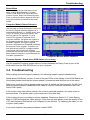
Status Menu
This status page shows information for all
daisy chained KVM Switches: Firmware
version, KVM Switch PCB model and max.
number of ports. Select one bank and press
Enter to access the status pages of the Cat.5
computer modules connected to that KVM
Switch.
Computer Module Status Submenu
Use this page to check the firmware version of
the Cat.5 Computer Modules attached to a
selected KVM Switch (i.e. 120208 shown here
is the FW version of the KVM Switch), and
perform manual FW upgrades. To do a
manual FW upgrade of individual Cat.5
computer modules, just select the module to
be upgraded and press Enter to confirm the
automatic upgrade. During the upgrade
process a download bar will appear indicating
the progress of the upgrade. In addition you
can alternatively press F4 to toggle between
manual and auto (for all Cat.5 modules
connected to this KVM Switch) upgrade mode.
More detailed information is provided with the
Firmware upgrade files.
Status Menu
Computer Module Status Submenu
Firmware Update – Stand-alone KVM Switch CAT32 only!
Use the supplied Firmware update cable to connect between the Daisy Chain In port of the
KVM switch and the DB9 RS-232 port on your computer.
3.4. Troubleshooting
Before calling technical support, please try the following steps for easy troubleshooting.
Stand-alone KVM Switch version: If none of the port LEDs or the display on the KVM Switch are
illuminated please check that the power adapter is connected and switched on at the mains.
Before you check any further please make sure that all cables are fitted correctly! Do NOT use
network connections but a dedicated RJ45 cable to connect Computer Modules to the KVM
Switch RJ45 ports!
If the monitor stays dark please check if the currently selected computer is in sleep mode or
powered down. If so please wake up the computer in the usual way.
If the monitor picture is not sharp or shows shadows: Please see Section 3.3. Video Setting
Menu in OSD and adjust the video settings. If this does not help please check the quality of the
UTP cable between KVM switch and Computer Access Module. Try replacing the cable, or use
a higher quality cable.
If you have forgotten the password please contact LINDY.
10
Troubleshooting
Q1. My keyboard and/or mouse are locked up. What can I do for troubleshooting without
rebooting the computer and/or KVM?
A1. First, unplug the console keyboard and mouse for a few seconds and plug them back in.
This will re-initialize the console keyboard and mouse, in case an initialization failure of the
console keyboard and mouse has happened. If this doesn't work, unplug the computer modules
PS/2 or USB connections from the computer for few seconds and plug it in again - alternatively
plug the USB connector into to a different USB port. If it is PS2, always connect the mouse
connection first, then the keyboard connection. This should bring back the computer module if
only re-initialization is required. If any of the above does not help then you may have to reboot
the computer for a complete reset of the computer keyboard and mouse.
The contact information for the LINDY technical support teams can be found on the LINDY
website for each country.
IP Access Troubleshooting – in case a KVM over IP module is installed
1. The remote mouse doesn’t work or is not synchronized
Make sure the mouse settings in CAT-32 IP match the mouse model. Use the Intelligent
Sync option from the Mouse Handling sub menu of the Remote Console Options menu.
2. The remote mouse does not work correctly
Try using the Reset Keyboard/Mouse option in the Maintenance section.
3. Login on CAT-32 IP switch fails.
Was the correct combination of user and password given? The default user name is super
and the password is pass. Furthermore, your browser must be configured to accept cookies.
4. The Remote Console window can’t connect to the CAT-32 IP.
Possibly a firewall prevents access to the Remote Console. Make sure the TCP port
numbers 443 or 80 are open for incoming TCP connections. Install the latest version of Java
Virtual Machine.
5. No connection can be established to the CAT-32 IP.
Check whether the network connection is working in general (ping the IP address of CAT-32
IP). If not, check the network hardware. Is the CAT-32 IP powered on? Check whether the IP
address of CAT-32 IP switch and all other IP related settings are correct! Also verify that all
the IP infrastructure of your LAN, including routers etc., is correctly configured.
6. Special key combinations, e.g. ALT+F2, ALT+F3 are intercepted by the console
system and not transmitted to the host.
You have to define a so-called Button Key. This can be done in the Remote Console
settings.
7. Every time I open a dialog box with some buttons, the mouse pointers are not
synchronised anymore
Please check if you have an option like ‘Automatically move mouse pointer to the default
button of dialog Unites’ enabled in the mouse settings of the operating system. This option
needs to be disabled.
For more detailed troubleshooting refer to the manual of the KVM over IP module.
11
Certifications, Recycling Information
CE Certification This equipment complies with the requirements relating to Electromagnetic Compatibility Standards
EN55022/EN55024 and the further standards cited therein. It must be used with shielded cables only except for the RJ45 cables.
It has been manufactured under the scope of RoHS compliance.
CE Konformitätserklärung Dieses Produkt entspricht den einschlägigen EMV Richtlinien der EU für IT-Equipment und
darf nur zusammen mit abgeschirmten Kabeln verwendet werden, RJ45 Kabel sollten ungeschirmt (UTP) sein.
Diese Geräte wurden unter Berücksichtigung der RoHS Vorgaben hergestellt.
Die formelle Konformitätserklärung können wir Ihnen auf Anforderung zur Verfügung stellen.
LINDY Herstellergarantie – Hinweis für Kunden in Deutschland LINDY gewährt für dieses Produkt über die gesetzliche
Regelung in Deutschland hinaus eine zweijährige Herstellergarantie ab Kaufdatum. Die detaillierten Bedingungen dieser Garantie
finden Sie auf der LINDY Website aufgelistet bei den AGBs.
FCC Statement
Shielded cables must be used with this equipment to maintain compliance with radio frequency energy emission regulations and ensure a
suitably high level of immunity to electromagnetic disturbances.
FCC Warning
This equipment has been tested and found to comply with the limits for a Class A digital device, pursuant to part 15 of the FCC Rules. These limits
are designed to provide reasonable protection against harmful interference when the equipment is operated in a commercial environment.
This equipment generates, uses, and can radiate radio frequency energy and, if not installed and used in accordance with the instruction manual,
may cause harmful interference to radio communications.
Operation of this equipment in a residential area is likely to cause harmful interference in which case the user will be required to correct the
interference at their own expense.
WEEE (Waste of Electrical and Electronic Equipment)
Recycling of Electronic Products
Europe, United Kingdom
In 2006 the European Union introduced regulations (WEEE) for the collection and recycling of all waste electrical and electronic
equipment. It is no longer allowable to simply throw away electrical and electronic equipment. Instead, these products must enter
the recycling process. Each individual EU member state has implemented the WEEE regulations into national law in slightly
different ways. Please follow your national law when you want to dispose of any electrical or electronic products. More details can
be obtained from your national WEEE recycling agency.
Germany / Deutschland
Die Europäische Union hat mit der WEEE Direktive Regelungen für die Verschrottung und das Recycling von Elektro- und
Elektronikprodukten geschaffen. Das deutsche Elektro-Gesetz verbietet das Entsorgen von entsprechenden, auch alten, Elektround Elektronikgeräten über die Hausmülltonne! Diese Geräte müssen dem Hersteller (LINDY) oder den lokalen Sammelsystemen
bzw. örtlichen Sammelstellen zugeführt werden! Dort werden sie kostenlos entgegen genommen. Die Kosten für den weiteren
Recyclingprozess übernehmen die Gerätehersteller.
France
En 2006, l'union Européenne a introduit la nouvelle réglementation (DEEE) pour le recyclage de tout équipement électrique et
électronique. Chaque Etat membre de l’Union Européenne a mis en application la nouvelle réglementation DEEE de manières
légèrement différentes. Veuillez suivre le décret d’application correspondant à l’élimination des déchets électriques ou
électroniques de votre pays.
Italy
Nel 2006 l’unione europea ha introdotto regolamentazioni (WEEE) per la raccolta e il riciclo di apparecchi elettrici ed elettronici.
Non è più consentito semplicemente gettare queste apparecchiature, devono essere riciclate. Ogni stato membro dell’EU ha
tramutato le direttive WEEE in leggi statali in varie misure. Fare riferimento alle leggi del proprio Stato quando si dispone di un
apparecchio elettrico o elettronico. Per ulteriori dettagli fare riferimento alla direttiva WEEE sul riciclaggio del proprio Stato.
LINDY No 39631, 39635
3rd Edition, August 2014
Tested to comply
with FCC Standards
For Commercial Use Only
www.lindy.com
12