1
1.1
Features
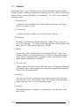
The Toshiba 610CT is one of the lightest and most advanced portable computers available.
Utilizing advanced technology and high-speed components, the 610CT offers excellent display
legibility, battery operation, and IBM PC/AT compatibility. The 610CT system unit has the
following features:
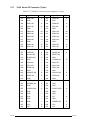
❑ Microprocessor
A Pentium® Processor 90MHz with Voltage Reduction Technology (VRT) that
operates at 90 MHz, 2.9 Volts.
❑ Cache memory
A 16 KB cache memory which is stored in the Pentium® Processor.
❑ Disk storage
An internal 720 million-byte (MB) Hard Disk Drive (HDD) with an average access
time of 15 milliseconds. A 3.5-inch external Floppy Disk Drive (FDD) supports 2HD
floppy disks (1.44 MB) and 2DD floppy disks (720 KB).
❑ Memory
Standard with 8 MB of CMOS Random Access Memory (RAM) 3.3 Volts. This
includes 640 KB of conventional memory and 7,360 KB of extended memory which
can be utilized as expanded memory compatible with the Lotus/Intel/Microsoft Expanded Memory Specifications (LIM-EMS).
❑ TFT color LCD
A high-resolution, Thin Film Transistor (TFT) full-color LCD displays 640x480 pixels.
The internal display controller supports VGA functions for internal display and Super
VGA (SVGA) for external display.
❑ Keyboard
An easy-to-use 82/84-key keyboard provides a numeric keypad overlay for fast numeric data entry or for cursor and page control. The computer’s keyboard supports
software that uses a 101- or 102-key enhanced keyboard.
❑ Batteries
Three different batteries: a main battery, a backup battery, and a Real Time Clock
(RTC) battery.
610CT
1-1
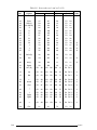
❑ Personal Computer Memory Card International Association (PCMCIA) card slot
Two PCMCIA slots enable you to install an MiNC Toshiba card modem or other
industry-standard PCMCIA release 2.01 card.
❑ Parallel port
One Centronics compatible parallel interface port.
❑ RS-232-C port
One 9-pin serial interface port.
❑ 3.5-inch external FDD port
One 3.5-inch external FDD port.
❑ Port replicator port
One port replicator port enables connection of an optional port replicator or external
monitor adapter. The port replicator allows connection of a PS/2 mouse, PS/2 keyboard, external monitor, printer, DC IN, serial I/O, and 3.5-inch FDD.
❑ Memory module slot
One Toshiba optional memory module slot enables you to install a Toshiba optional
memory module.
❑ AccuPoint
A pointer control stick, located in the center of the keyboard.
❑ Sound System
A Sound Blaster™ Pro™ compatible sound system to give multimedia capability with
a built-in microphone and speaker. The sound system provides a volume control dial
and headphone and microphone jacks to connect external audio devices.
1-2
610CT
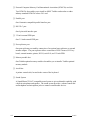
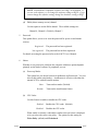
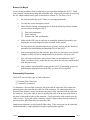
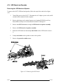
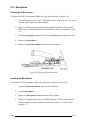
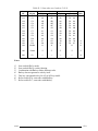
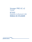
The 610CT Personal Computer is shown in figure 1-1.
Figure 1-1 610CT
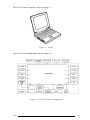
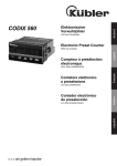
The 610CT system configuration is shown in figure 1-2.
Figure 1-2 610CT system unit configuration
610CT
1-3
1.2
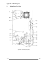
System Unit Block Diagram
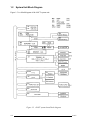
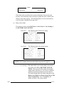
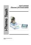
Figure 1-3 is a block diagram of the 610CT system unit.
Figure 1-3 610CT system board block diagram
1-4
610CT
The 610CT system board has the following major components:
❑ One Intel Pentium-90 MHz with VRT 64-bit microprocessor
Intel Pentium processor operates at 90 MHz and 2.9 volts
❑ Standard RAM
8 MB, four 1Mx16-bit chips
3.3 volt operation
No parity bit
Access time 60 ns
Data transfer is 64-bit width
Available hyper page mode (EDO)
❑ BIOS ROM (Flash EEPROM)
128 MB (one 128Kx8-bit chip) memory
64 KB in the ROM are used for system BIOS
40 KB in the ROM are used for VGA BIOS
40 KB in the ROM are reserved
Access time 150 ns
Data transfer is 8-bit width
❑ Video RAM
1 MB (Two 256Kx16-bit DRAM)
5 volt operation
❑ Optional memory
One expansion memory slot is available for 8, 16, and 32 MB memory modules, which
may consist of 1 MBx16-bit chips
Total maximum memory size is 40 MB (if a 32 MB memory module is installed)
3.3 volt operation
No parity bit
Access time 60 ns
Data transfer is 64-bit width
Available hyper page mode (EDO)
❑ One super integration (SI)
The following components:
- Two DMACs
82C37 equivalent
- Two PICs
82C59 equivalent
- Two SIOs
16550 equivalent
- One PIT
82C54 equivalent
- One FDC
TC8565 equivalent
- One VFO
TC8568 equivalent
- One I/O port decode
- One SIO port control
- One printer port control supported ECP
- One FDD control
- One speaker control
- One power communication control
610CT
(One SIO is not used)
1-5
❑ System Controller Gate Array (SCPCNT6-GA)
This gate array has the following functions:
CPU control
SMI control
CPU clock control
Memory control
64-bit bus memory control
32-bit bus memory control
Bus control
64-bit data bus <==>32-bit data bus
32-bit local bus control
Address latch control
I/O register control
Processing speed control
❑ ISA Bus Controller Gate Array (SISCNT3-GA)
This gate array has the following functions:
Bus control
32-bit data bus <==> 16-bit data bus
ISA bus interface control
ISA bus access control
DMAC control
DMA address generation
I/O control
Suspend/Resume sequence
Memory control
IAS bus interface control
Refresh address generation
I/O register control
Suspend/Resume sequence
❑ PCMCIA Controller Gate Array
This gate array has the following functions:
PCMCIA memory card control
❑ I/O Controller Gate Array (IOCNT-GA)
This gate array has the following functions:
Internal Communication controller
KBC, main CPU communication register file
KBC interrupt controller
Others
KBC communication controller
Contrast adjust, speaker volume adjust, PWM control
Sound board interface
BIOS-ROM interface
SIM control
1-6
610CT
❑ Video Controller
This video controller controls internal TFT color LCD and external SVGA compatible
CRT.
❑ Keyboard Controller (KBC)
One M38802M4 chip is used.
This KBC includes the keyboard scan controller and keyboard interface controller.
The KBC controls the internal keyboard, external keyboard, PS/2 mouse.
❑ Real Time Clock (RTC)
One T9934 chip is used.
The T9934 has 128 of bytes memory. Fourteen bytes of memory are used for the
calendar and clock. The remaining 114 bytes are used for the system configuration
data.
610CT
1-7
1.3
3.5-inch External Floppy Disk Drive
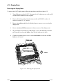
The 610CT 3.5-inch external Floppy Disk Drive (FDD) is a thin, high-performance reliable
drive that supports 720-KB (formatted) 2DD and 1.44-MB (formatted) 2HD 3.5-inch floppy
disks.
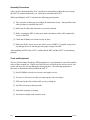
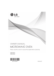
The 610CT FDD is shown in figure 1-4.
Figure 1-4 3.5-inch external FDD
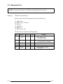
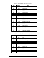
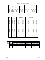
The specifications for the FDD are listed in table 1-1.
Table 1-1 3.5-inch external FDD specifications
Item
2-MB mode
1-MB mode
2,000
1,440
1,000
720
2
2
80
80
Access time (ms)
Track to track
Average
Head settling time
3
181
15
3
181
15
Recording track density (tpi)
135
135
Data transfer rate (Kbps)
500
250
Rotation speed (rpm)
300
300
Storage capacity (KB)
Unformatted
Formatted
Number of heads
Number of cylinders
Recording method
1-8
Modified Frequency Modulation (MFM)
610CT
1.4
2.5-inch Hard Disk Drive
The 720 MB Hard Disk Drive (HDD) is a random access non-volatile storage device. It has a
non-removable 2.5-inch magnetic disk and mini-winchester type magnetic heads.
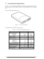
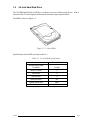
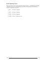
The HDD is shown in figure 1-5.
Figure 1-5 2.5-Inch HDD
Specifications for the HDD are listed in table 1-2.
Table 1-2 2.5-inch HDD specifications
610CT
Items
(MK1724FCV)
Storage capacity (MB)
Formatted
722 MB
Number of disks
2
Data heads
4
Data surfaces
4
Bytes per sector
512
Rotation speed (rpm)
4000
Recording method
1-7 RLL
1-9
1.5
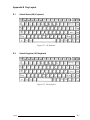
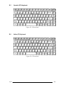
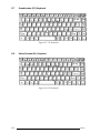
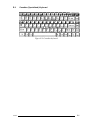
Keyboard
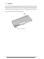
The 82-(USA) or 84-(European) keyboard is mounted on the 610CT system unit. The keyboard is connected to the keyboard controller on the system board through a 25-pin flat cable.
The pointer control stick, located in the center of the keyboard, provides convenient control
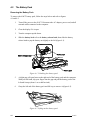
of the cursor without requiring desk space for a mouse. The keyboard is shown in figure 1-6.
See Appendix E for optional keyboard configurations.
Figure 1-6 Keyboard
1-10
610CT
1.6
TFT Color LCD
The TFT Color Liquid Crystal Display (LCD) contains an LCD module, a Fluorescent Lamp
(FL), and an FL inverter board.
1.6.1
LCD Module
The 610CT TFT color LCD supports 640x480 pixels with an internal display controller and
256K colors for graphics and characters. This controller includes the functions of Video
Graphics Array (VGA) and Super VGA (SVGA) for external display.
The LCD receives 9-bit data signals, data enable signals, and has a shift clock for data transmission. All signals are CMOS-level compatible.
The TFT LCD is shown in figure 1-7.
Figure 1-7 TFT color LCD
The specifications for the LCD are listed in table 1-3.
Table 1-3 TFT color LCD specifications
Item
Specifications
Number of dots
(dots)
640 x 480
Dot pitch
(mm)
0.3 x 0.3
Display area
(mm)
192 x 144
Contrast
610CT
100
FL current
(mA)
4.0
FL frequency
(KHz)
100 (max)
1-11
1.6.2
Fluorescent Lamp (FL) Inverter Board
The FL inverter board supplies high frequency current to light the LCD’s Fluorescent Lamp.
The specifications for the FL inverter are described in table 1-4.
Table 1-4 FL inverter board specifications
Item
Input
Output
1-12
Specifications
Voltage
(VDC)
10
Power
(W)
3
Voltage
(VAC)
1,100 (r.m.s.)
Current
(mA)
5.0
Frequency
(KHz)
44
610CT
1.7
Power Supply
The power supply provides five kinds of voltages to the 610CT system board. The power
supply has one microprocessor which operates at 500 KHz and performs the following functions:
1.
Determines if the AC adapter or battery is connected to the computer.
2.
Detects DC output and circuit malfunctions.
3.
Controls the LED icon and speaker.
4.
Turns the battery charging system on and off and detects a fully charged battery.
5.
Determines if the power can be turned on and off.
6.
Provides more accurate detection of a low battery.
7.
Calculates the remaining battery capacity.
The power supply output rating is specified in table 1-5.
Table 1-5 Power supply output rating
Name
DC
voltage
(V)
VCC
+5
±5
Display
DSPV
+15
±5
RS-232C
P+12V
+12
±5
CPU, RAM
B3V
+3.3
±5
VGA,I/O
B5V
+5
±5
Use for
System logic, FDD, HDD,
610CT
Regulation
tolerance
(%)
1-13
1.8
Batteries
The 610CT has three types of batteries:
❑ Main battery pack
❑ Backup battery
❑ Real Time Clock (RTC) battery
These battery specifications are listed in table 1-6.
Table 1-6 Battery specifications
Battery name
Material
Output voltage
Capacity
Main battery
Lithium-Ion
10.8 V
4,000 mAH
Backup battery
Nickel Metal Hydride
6.0 V
110 mAH
RTC battery
Nickel Metal Hydride
3.6 V
30 mAH
1.8.1
Main Battery
The removable main battery pack is the computer’s main power source when the AC adapter
is not attached. The main battery recharges the backup battery when the system’s power is
on. The backup and main battery maintain the state of the computer when you enable
AutoResume.
❏ Battery Indicator
The Battery indicator is located on the front side of the 610CT. The indicator shows
the status of the removable battery pack, power supply, and AC adapter.
The status of each can be determined by color:
Orange
The battery is being charged. (AC adapter is attached.)
Green
The battery is fully charged. (AC adapter is attached.)
No light The AC adapter is disconnected from the computer; or the AC
adapter is connected, but it cannot charge the battery for one of the
following reasons:
1-14
−
The battery is extremely hot. Allow the computer and the
battery to reach room temperature before attempting to charge
the battery.
−
The battery is almost fully discharged. The battery will not
begin charging immediately in this state, it will begin charging a
few minutes after the AC adapter is connected.
−
The AC adapter is not receiving power.
610CT
1.8.2
Battery Charging Control
Battery charging is controlled by a microprocessor that is mounted on the power supply. The
microprocessor controls whether the charge is on or off and detects a full charge when the AC
adapter and battery are attached to the computer. The system charges the battery using quick
charge or trickle charge.
When the AC adapter is attached, there are two types of charge: quick charge when the
system is powered off, and trickle charge when the system is powered on.
Table 1-7 Time required for battery charges
Status
Charging time
Quick charge
(power off)
About 4 hours
Trickle charge
(power on)
About 5 to 8 hours
❏ Quick Battery Charge
If one of the following occurs, the battery quick-charge process stops.
1.
The battery becomes fully charged
2.
The AC adapter or battery is removed.
3.
The battery or AC adapter output voltage is abnormal.
4.
The charge current is abnormal.
❏ Trickle Battery Charge
When the main battery is fully charged and the AC adapter is attached, the power
supply microprocessor automatically changes quick charge to trickle charge.
610CT
1-15
1.8.3
Backup Battery
The backup battery maintains data for AutoResume. The power source used to back-up the
AutoResume data is determined according to the following priority:
AC adapter > Main battery > Backup battery
The backup battery is charged by the main battery or AC adapter when the system is powered
on. Table 1-8 shows the charging time and data preservation period of the backup battery.
Table 1-8 Backup battery charging/data preservation time
Backup Battery
Charging Time
Time
Power On
40 H
Power Off (with AC Adapter)
40 H
Power Off (Without AC Adapter) Doesn’t charge
Data preservation period (full charge)
1.8.4
8H
RTC Battery
The RTC battery provides power to keep the current date, time and other setup information in
memory while the computer is turned off. Table 1-9 shows the charging time and data preservation period of the RTC battery.
Table 1-9 RTC battery charging/data preservation time
RTC Battery
Charging Time
Time
Power On
70 H
Power Off
Doesn’t charge
Data preservation period (full charge)
1-16
1 month
610CT
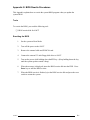
2.1
Troubleshooting
Chapter 2 describes how to determine if a Field Replaceable Unit (FRU) in the 610CT is
causing the computer to malfunction. The FRUs covered are:
1.
Power Supply
2.
System Board
3.
Floppy Disk Drive
4.
Hard Disk Drive
5.
Keyboard
6.
Display
The Diagnostics Disk operations are described in Chapter 3 and detailed replacement procedures are given in Chapter 4.
The following tools are necessary for implementing the troubleshooting procedures:
1.
A 610CT Diagnostics Disk
2.
A Phillips screwdriver (2 mm)
3.
A Toshiba MS-DOS system disk(s)
4.
A 2DD or 2HD formatted work disk for floppy disk drive testing
5.
A cleaning kit for floppy disk drive troubleshooting
6.
A printer port LED
7.
An RS-232-C wraparound connector
8.
A printer wraparound connector
9.
A multimeter
10.
An external monitor adapter
11.
An external monitor
610CT
2-1
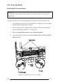
2.2
Troubleshooting Flowchart
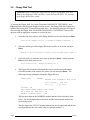
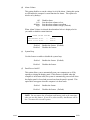
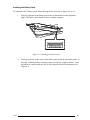
Use the flowchart in figure 2-1 as a guide for determining which troubleshooting procedures
to execute. Before going through the flowchart steps, verify the following:
❑ Ask the user if a password is registered and, if it is, ask him or her to enter the password. If the user has forgotten the password, connect the printer port wraparound
board (F31PRT), then turn the POWER switch on. The computer will override the
password function by erasing the current password.
❑ Verify with the customer that Toshiba MS-DOS is installed on the hard disk. NonToshiba operating systems can cause the computer to malfunction.
❑ Make sure all optional equipment is disconnected from the computer.
❑ Make sure the floppy disk drive is empty.
2-2
610CT
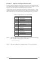
Figure 2-1 Troubleshooting flowchart (1/2)
610CT
2-3
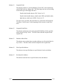
Figure 2-1 Troubleshooting flowchart (2/2)
If the diagnostics program cannot detect an error, the problem may be intermittent. The
Running Test program should be executed several times to isolate the problem. Check the
Log Utilities function to confirm which diagnostic test detected an error(s), then perform the
appropriate troubleshooting procedures as follows:
2-4
1.
If an error is detected on the system test, memory test, display test, ASYNC test,
printer test, or real timer test, perform the system board troubleshooting procedures in section 2.4.
2.
If an error is detected on the keyboard test, perform the keyboard troubleshooting
procedures in section 2.7.
3.
If an error is detected on the floppy disk test, perform the floppy disk drive
troubleshooting procedures in section 2.5.
4.
If an error is detected on the hard disk test, perform the hard disk drive
troubleshooting procedures in section 2.6.
610CT
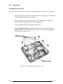
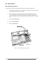
2.3
Power Supply Troubleshooting
The power supply controls many functions and components in the 610CT. To determine if
the power supply is functioning properly, start with Procedure 1 and continue with the other
Procedures as instructed. The procedures described in this section are:
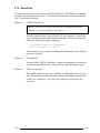
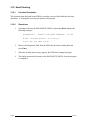
Procedure 1:
DC IN Icon Indicator Check
Procedure 2:
Battery LED Indicator Check
Procedure 3:
Connection and Replacement Check
Procedure 1
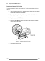
DC IN Icon Indicator Check
The 610CT AC adapter converts AC power to DC power and contains a charging circuit
which charges the batteries. The adapter connects to the DC IN socket connector on the back
side of the computer. When the AC adapter is connected to the computer and the power is
turned off, the AC adapter charges the batteries.
The DC IN icon displays whether or not the AC adapter is connected and supplying power.
When the DC IN icon is green, the AC adapter is connected and supplying power to the
610CT.
If the DC IN icon does not light, the AC adapter is not supplying power or the AC adapter is
not attached to the 610CT, go to Check 1.
If the DC IN icon is flashing orange, the AC adapter’s voltage supply is abnormal or the
power supply is not functioning properly, go to Check 1.
If any of the above indicator conditions are abnormal, make sure the DC IN icon’s LED
indicator lights are not burned out before performing the following checks:
Check 1
Make sure the correct AC adapter cable is firmly plugged into the DC IN socket
on the back of the computer.
Check 2
If the DC IN icon flashes orange when the AC adapter is connected, its voltage
output is abnormal. Connect a new AC adapter and turn the 610CT on again to
verify the indicator condition.
Check 3
The battery pack may be malfunctioning. Replace the battery pack with a new one
and turn the computer on again. If the problem still exists, perform Check 4.
Check 4
Place the 610CT in an environment between –20°C and 70°C until it is at the
ambient temperature. Repeat the steps which caused the computer to operate
abnormally. If the same problem still occurs, perform Procedure 3.
610CT
2-5
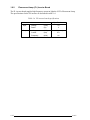
Procedure 2
Battery LED Indicator Check
The Battery LED indicator shows the battery charging status. The Battery LED, identified by
a battery icon on the front of the computer, glows amber when the AC adapter is charging the
610CT battery pack.
If the Battery LED indicator glows green, the AC adapter is connected and the battery is fully
charged.
If the Battery LED indicator glows amber, the AC adapter is connected and the battery is
being charged.
If the Battery LED indicator does not glow, go to Check 1.
Check 1
Make sure the AC adapter cable and AC cord are firmly plugged into the DC IN
socket and wall outlet. If these cables are connected correctly, go to Check 2.
Check 2
Make sure the battery pack is installed in the computer correctly. If the battery
pack is installed correctly, go to Check 3.
Check 3
Remove the battery pack and check that the battery and system board terminals
are clean and not bent.
If the battery and/or terminal appears dirty, clean it/them gently with a cotton
swab dipped in alcohol.
If either terminal looks bent or damaged, replace the battery or the system board.
If the terminals are clean and not bent, go to Check 4.
Check 4
Connect a new AC adapter. If the Battery LED indicator still does not glow, go
to Check 5.
Check 5
Install a new battery pack. If the Battery LED indicator still does not glow, go to
Procedure 3.
2-6
610CT
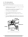
Procedure 3
Connection and Replacement Check
The power supply board is connected to the system board. This connection may become
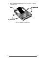
damaged or disconnected from the system board. Disassemble the 610CT following the steps
described in chapter 4, Replacement Procedures, and perform the following checks.
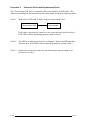
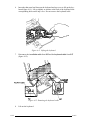
Check 1
Make sure the power supply board and system board are firmly connected to each
connector.
AC Adapter
Power Supply Board
System Board
If any of these boards is disconnected, connect it and repeat Procedure 1. If the
system is still not functioning properly, perform Check 2.
Check 2
The power supply board may be defective or damaged. Replace the power supply
board with a new one following the steps in chapter 4, Replacement Procedures.
If the system is still not functioning properly, perform Check 3.
Check 3
Replace the system board with a new one and restart the system. If the problem
still exists, other FRUs may be damaged.
610CT
2-7
2.4
System Board Troubleshooting
This section describes how to determine if the system board is defective or not functioning
properly. Start with Procedure 1 and continue with the other procedures as instructed. The
procedures described in this section are:
Procedure 1:
Message Check
Procedure 2:
Printer Port LED Check on Boot Mode
Procedure 3:
Printer Port LED Check on Resume Mode
Procedure 4:
Diagnostic Test Program Execution Check
Procedure 5:
Replacement Check
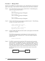
Procedure 1
Message Check
When the power is turned on, the system performs the Initial Reliability Test (IRT) installed in
the BIOS ROM. The IRT tests each IC on the system board and initializes it.
❑ If an error message is shown on the display, perform Check 1.
❑ If there is no error message, go to Procedure 2.
❑ If Toshiba MS-DOS is properly loaded, go to Procedure 3.
Check 1
If one of the following error messages is displayed on the screen, press the F1 key
as the message instructs. These errors occur when data is lost or when the system
configuration preserved in the RTC memory (CMOS type memory) is not the
same as the actual configuration.
If you press the F1 key as the message instructs, the system configuration in the
RTC memory configuration is set to the default setting. If error message (b)
appears often when the power is turned on, replace the RTC battery. If any other
error message is displayed, perform Check 2.
(a) *** Error in CMOS.
Check system.
Bad HDD type ***
Then press [F1] key ......
(b) *** Error in CMOS.
Check system.
Bad battery ***
Then press [F1] key ......
(c) *** Error in CMOS.
Check system.
Bad check sum ***
Then press [F1] key ......
(d) *** Error in CMOS.
Check system.
Bad memory size ***
Then press [F1] key ......
(e) *** Error in CMOS.
Check system.
2-8
Bad time function ***
Then press [F1] key ......
610CT
Check 2
If the following error message is displayed on the screen, press any key as the
message instructs:
WARNING:
RESUME FAILURE.
PRESS ANY KEY TO CONTINUE.
This error message appears when data stored in RAM under the resume function is
lost because the battery has become discharged or the system board is damaged.
Go to Procedure 3.
If any other message appears, perform Check 3.
610CT
2-9
Check 3
The IRT checks the system board. When the IRT detects an error, the system
stops or an error message appears.
If one of the following error messages (1) through (7), (9) through (18), (23), or
(24) is displayed, replace the system board.
If error message (8) is displayed, go to the Keyboard Troubleshooting Procedures
in section 2.7.
If error message (19) or (20) is displayed, go to the HDD Troubleshooting Procedures in section 2.6.
If error message (21) or (22) is displayed, go to the FDD Troubleshooting Procedures in section 2.5.
2-10
(1)
TIMER CH.2 OUT ERROR
(2)
PIT ERROR
(3)
MEMORY REFRESH ERROR
(4)
FIRST 64KB MEMORY ERROR
(5)
RTC ERROR
(6)
CRTC ERROR
(7)
VRAM ERROR
(8)
KBC ERROR
(9)
SYSTEM MEMORY ERROR
(10)
SYSTEM MEMORY PARITY ERROR
(11)
EXTENDED MEMORY ERROR
(12)
EXTENDED MEMORY PARITY ERROR
(13)
DMA PAGE REGISTER ERROR
(14)
DMAC #1 ERROR
(15)
DMAC #2 ERROR
(16)
PIC #1 ERROR
(17)
PIC #2 ERROR
(18)
HDC ERROR
(19)
HDD #0 ERROR
(20)
HDD #1 ERROR
(21)
NO FDD ERROR
(22)
FDD ERROR
(23)
TIMER INTERRUPT ERROR
(24)
RTC UPDATE ERROR
610CT
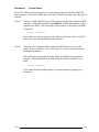
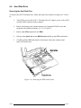
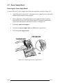
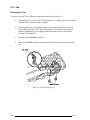
Procedure 2
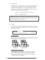
Printer Port LED Check on Boot Mode
The printer port LED displays the IRT status and test status by turning lights on and off as an
eight-digit binary value for boot mode. Figure 2-2 shows the printer port LED.
Figure 2-2 Printer port LED
To use the printer port LED follow these steps:
1.
Turn on the 610CT power, then set to boot mode.
2.
Turn off the computer’s power.
3.
Plug the printer port LED into the 610CT Printer connector.
4.
Hold down the space bar and turn on the computer's power.
5.
Read the LED status from left to right as you are facing the back of the computer.
6.
Convert the status from binary to hexadecimal notation.
7.
If the final LED status is FFh (normal status), go to Procedure 3.
8.
If the final LED status matches any of the test status values in table 2-1, perform
Check 1.
NOTE: If an error condition is detected by the IRT test, the printer port LED
displays an error code after the IRT test ends. For example, when the printer port
LED displays 22 and halts, the IRT test has already completed the KBC test. In
this instance, the IRT indicates an error has been detected during the next item,
system memory test.
610CT
2-11
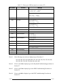
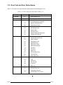
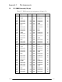
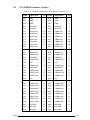
Table 2-1 Printer port LED boot mode error status (1/2)
Error status
Test item
01H
Pre-init for warm start
test
05H
PIT test
Message
—
TIMER CH.2 OUT ERROR
PIT ERROR
READ DATA = XXH
WRITE DATA = XXH
06H
PIT initialization
07H
PIT function test
MEMORY REFRESH ERROR
0AH
First 64KB memory test
FIRST 64KB MEMORY ERROR
0BH
System memory
initialization
—
0DH
Interrupt vector
initialization
—
15H
RTC test
RTC ERROR
READ DATA = XXH
WRITE DATA = XXH
16H
CMOS RAM test
****Error in CMOS.
****Error in CMOS.
****Error in CMOS.
****Error in CMOS.
****Error in CMOS.
****Error in CMOS.
Check system. Then
18H
PIC initialization
1FH
Display initialization
—
Bad battery****
Bad check sum****
Bad configuration****
Bad memory size****
Bad HDD type****
Bad time function****
press [F1] key
—
CRTC ERROR
VRAM ERROR
READ DATA = XXXXXXXXH
WRITE DATA = XXXXXXXXH
22H
KBC test
KBC ERROR
25H
System memory test
SYSTEM MEMORY ERROR
ADDRESS
= XXXXXXXXH
READ DATA = XXXXXXXXH
WRITE DATA = XXXXXXXXH
SYSTEM MEMORY PARITY ERROR
ADDRESS = XXXX0000H - XXXXFFFFH
30H
Extended memory test
EXTENDED MEMORY ERROR
ADDRESS
= XXXXXXXXH
READ DATA = XXXXXXXXH
WRITE DATA = XXXXXXXXH
EXTENDED MEMORY PARITY ERROR
ADDRESS = XXXX0000H - XXXXFFFFH
40H
2-12
DMA page register test
DMA PAGE REGISTER ERROR
READ DATA = XXH
WRITE DATA = XXH
610CT
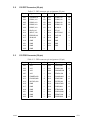
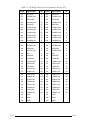
Table 2-1 Printer port LED boot mode error status (2/2)
Error status
41H
Test item
DMAC test
Message
DMAC #1 ERROR
READ DATA = XXXXH
WRITE DA = XXXXH
DMAC #2 ERROR
READ DATA = XXXXH
WRITE DATA = XXXXH
42H
DMAC initialization
4AH
PIC test
PIC #1 ERROR
READ DATA = XXH
WRITE DATA = XXH
PIC #2 ERROR
READ DATA = XXH
WRITE DATA = XXH
54H
Keyboard test
KEYBOARD ERROR
55H
KBC initialization
KBC ERROR
5AH
Mouse initialization
60H
HDD initialization
HDC ERROR
HDC #0 ERROR
HDC #1 ERROR
65H
FDD initialization
NO FDD ERROR
-
FDD ERROR
70H
Printer test
-
80H
RS-232-C test
-
90H
Timer initialization
TIMER INTERRUPT ERROR
RTC UPDATE ERROR
A0H
NDP initialization
-
A6H
Expansion I/O ROM
-
FFH
Expansion system ROM
-
Check 1
If the following error codes are displayed, go to Procedure 5.
01h, 05h, 06h, 07h, 0Ah, 0Bh, 0Dh, 15h, 16h, 18h, 1Fh, 22h, 25h, 30h, 40h,
41h, 42h, 54h, 55h, 65h, 70h, 80h, 90h, A0h, A6h
Check 2
If error code 4Ah is displayed, go to the Keyboard Troubleshooting procedures in
Section 2.7.
Check 3
If error code 5Ah is displayed, go to the HDD Troubleshooting Procedures in
Section 2.6.
Check 4
If error code 60h is displayed, go to the FDD Troubleshooting Procedures in
Section 2.5.
610CT
2-13
Procedure 3
Printer Port LED Check on Resume Mode
The printer port LED displays the IRT status and test status by turning lights on and off as an
eight-digit binary value for resume mode.
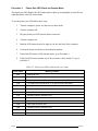
To use the printer port LED follow these steps:
1.
Turn the computer's power on, then set to resume mode.
2.
Turn the computer off.
3.
Plug the printer port LED into the printer connector.
4.
Turn the computer on.
5.
Read the LED status from left to right as you face the back of the computer.
6.
Convert the status from binary to hexadecimal notation.
7.
If the final LED status is FFh (normal status), go to Procedure 4.
8.
If the final LED status matches any of the test status values in table 2-2, go to
procedure 5.
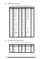
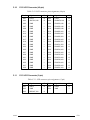
Table 2-2 Printer port LED resume mode error status
Error status
2-14
Meaning of status
00H
RAM BIOS error
F0H
Press the reset switch
F1H
Suspend process error (The system will suspend while FDD is accessed, etc.)
F2H
The system has optional ROM, or an optional card (CGA, MDA)
F4H
Backup RAM checksum error
F5H
Main memory checksum error
F6H
Video RAM checksum error
F7H
Extended memory checksum error
F8H
Backup RAM checksum error
F9H
Main memory checksum error
FAH
Video RAM checksum error
FBH
Extended memory checksum error
FDH
Card modem error
FEH
Password error
610CT
Procedure 4
Diagnostic Test Program Execution Check
Execute the following tests from the Diagnostic Test Menu. Refer to chapter 3, Tests and
Diagnostics, for more information on how to perform these tests.
1.
2.
3.
4.
5.
6.
7.
System test
Memory test
Printer test
ASYNC test
Real Timer test
NDP test
PCMCIA test
If an error is detected during any of these tests, go to Procedure 5.
Procedure 5
Replacement Check
The system board may be damaged. Disassemble the 610CT following the steps described in
chapter 4, Replacement Procedures, and perform the following check:
Check
610CT
Replace the system board with a new one. If the problem still exists, other FRUs
may be damaged.
2-15
2.5
Floppy Disk Drive Troubleshooting
This section describes how to determine if the 610CT 3.5-inch external floppy disk drive is
functioning properly. If the 3.5-inch external FDD is not connected to the computer, connect
it and perform the steps below starting with Procedure 1 and continuing with the other procedures as required.
Procedure 1:
FDD Head Cleaning Check
Procedure 2:
Diagnostic Test Program Check
Procedure 3:
Connector Check and Replacement Check
Procedure 1
FDD Head Cleaning Check
FDD head cleaning is one option available in the Diagnostic Program. Detailed operation is
given in chapter 3, Tests and Diagnostics.
After loading Toshiba MS-DOS, run the Diagnostic Program and then clean the FDD heads
using the cleaning kit. If the FDD still does not function properly after cleaning, go to Procedure 2.
If the test program cannot be executed on the 610CT, go to Procedure 3.
2-16
610CT
Procedure 2
Diagnostic Test Program Execution Check
The Floppy Disk Drive Diagnostic Test program is stored on the 610CT Diagnostics Disk.
After loading Toshiba MS-DOS, run the diagnostic program. Refer to Chapter 3, Tests and
Diagnostics, for more information about the diagnostics test procedures.
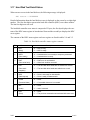
Floppy disk drive test error codes and their status names are described in table 2-3. Make
sure the floppy disk in the FDD is formatted correctly and that the write protect tab is disabled. If any other errors occur while executing the FDD diagnostics test, go to Check 1.
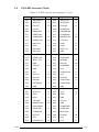
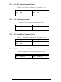
Table 2-3 Floppy disk drive error code and status
Code
Check 1
Status
01h
Bad command
02h
Address mark not found
03h
Write protected
04h
Record not found
06h
Media removed on dual attach card
08h
DMA overrun error
09h
DMA boundary error
10h
CRC error
20h
FDC error
40h
Seek error
60h
FDD not drive
80h
Time out error (Not ready)
EEh
Write buffer error
FFh
Data compare error
If the following message is displayed, disable the write protect tab on the floppy
disk. If any other message appears, perform Check 2.
Write protected
Check 2
610CT
Make sure the floppy disk is formatted correctly. If it is, go to Procedure 3.
2-17
Procedure 3
Connector Check and Replacement Check
The 3.5-inch Floppy Disk Drive is connected to the system board by the FDD cable. This
cable may be damaged or disconnected from the system board. Perform the following checks:
Check 1
Make sure the FDD cable is firmly connected to the system board.
3.5-inch external FDD
System Board
If this cable is disconnected, connect it to the system unit and repeat Procedure 2.
If the FDD is still not functioning properly, perform Check 2.
Check 2
The FDD or its cable may be defective or damaged. Replace the FDD and cable
with new ones. If the FDD is still not functioning properly, perform Check 3.
Check 3
Replace the system board with a new one following the steps in chapter 4, Replacement Procedures.
2-18
610CT
2.6
Hard Disk Drive Troubleshooting
To determine if the hard disk drive is functioning properly, perform the procedures below
starting with Procedure 1. Continue with the other procedures as instructed.
Procedure 1:
Partition Check
Procedure 2:
Message Check
Procedure 3:
Format Check
Procedure 4:
Diagnostic Test Program Execution Check
CAUTION: The contents of the hard disk will be erased when the HDD troubleshooting procedures are executed. Transfer the contents of the hard disk to a floppy disk(s)
using the Toshiba MS-DOS BACKUP command. Refer to the Toshiba MS-DOS
Manual for more information about how to perform the BACKUP command.
Procedure 1
Partition Check
Insert the Toshiba MS-DOS system disk and turn the computer on, then perform the following checks:
Check 1
Type C: and press Enter. If you cannot change to drive C, go to Check 2. If you
can change to drive C, go to Procedure 2.
Check 2
Type FDISK and press Enter. Choose Display Partition Information from the
FDISK menu. If drive C is listed, go to Check 3. If drive C is not listed, return to
the FDISK menu and choose the option to create a DOS partition on drive C.
Recheck the system. If the problem still exists, go to Procedure 2.
Check 3
If drive C is listed as active in the FDISK menu, go to Check 4. If drive C is not
listed as active, return to the FDISK menu and choose the option to set the active
partition for drive C. Recheck the system. If the problem still exists, go to Procedure 2.
Check 4
Remove the system disk from the FDD and cold boot the computer. If the problem still exists, go to Procedure 2. Otherwise, the HDD is operating normally.
610CT
2-19
Procedure 2
Message Check
When the 610CT HDD does not function properly, some of the following error messages may
appear on the display. Start with Check 1 below and perform the other checks as instructed.
Check 1
If any of the following messages appear, perform Check 2. If the following messages do not appear, perform Check 4:
HDC ERROR
(After 5 seconds this message will disappear)
or
HDD #0 ERROR
(After 5 seconds this message will disappear)
or
HDD #1 ERROR
(After 5 seconds this message will disappear)
Check 2
If either of the following messages appears, perform Procedure 3. If the following
messages do not appear, perform Check 3.
Insert system disk in drive
Press any key when ready .....
or
Non-System disk or disk error
Replace and press any key
Check 3
Using the Toshiba MS-DOS system disk, install a system program on the hard disk
using the SYS command.
If the following message appears on the display, the system program has been
transferred to the HDD. Restart the 610CT. If the error message still appears,
perform Check 4.
System transferred
Check 4
The HDD is connected to the system board. This connection can become damaged or disconnected. Disassemble the 610CT as described in chapter 4, Replacement Procedures. If the HDD is not connected to the flexible cable, connect it to
the flexible cable and return to Procedure 1. If the flexible cable is not connected
to the system board, connect it to the system board and return to Procedure 1. If
the HDD and flexible cable are firmly connected to the system board, perform
Procedure 3.
System Board
2-20
HDD
610CT
Procedure 3
Format Check
The 610CT HDD is formatted using the low level format program and the MS-DOS FORMAT program. To format the HDD, start with Check 1 below and perform the other steps as
required.
Check 1
Using the Toshiba MS-DOS system disk, partition the hard disk using the FDISK
command. Format the hard disk using FORMAT C:/S/U to transfer the system
program to the HDD. If the following message appears on the display, the HDD
is formatted.
Format complete
If any other error message appears on the display, refer to the Toshiba MS-DOS
Manual for more information and perform Check 2.
Check 2
Using the 610CT Diagnostic Disk, format the HDD with a low level format
option. Refer to Chapter 3, Tests and Diagnostics, for more information about
the diagnostic program.
If the following message appears on the display, the HDD low level format is
complete. Partition and format the HDD using the MS-DOS FORMAT command.
Format complete
If you cannot format the HDD using the Test and Diagnostic program, go to
Procedure 4.
610CT
2-21
Procedure 4
Diagnostic Test Program Execution Check
The HDD test program is stored in the 610CT Diagnostics Disk. Perform all of the HDD
tests in the Hard Disk Drive Test. Refer to chapter 3, Tests and Diagnostics, for more information about the HDD test program.
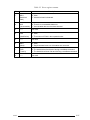
If an error is detected during the HDD test, an error code and status will be displayed; perform Check 1. The error codes and statuses are described in table 2-4. If an error code is not
generated, the HDD is operating properly.
Table 2-4 Hard disk drive error code and status
Code
Status
01h
Bad command
02h
Bad address mark
04h
Record not found
05h
HDC not reset
07h
Drive not initialized
08
HDC overrun (DRQ)
09h
DMA boundary error
0Ah
Bad sector error
0Bh
Bad track error
10h
ECC error
11h
ECC recover enabled
20h
HDC error
40h
Seek error
80h
Time out error
AAh
Drive not ready
BBh
Undefined error
CCh
Write fault
E0h
Status error
EEh
Access time out error
FFh
Data compare error
Check 1
Replace the HDD unit with a new one following the instructions in chapter 4,
Replacement Procedures. If the HDD is still not functioning properly, perform
Check 2.
Check 2
Replace the flexible cable with a new one following the instructions in chapter 4.
If the HDD still not functioning properly, replace the system board.
2-22
610CT
2.7
Keyboard Troubleshooting
To determine if the 610CT keyboard is functioning properly, perform the following procedures. Start with Procedure 1 and continue with the other procedures as instructed.
Procedure 1:
Diagnostic Test Program Execution Check
Procedure 2:
Connector and Replacement Check
Procedure 1
Diagnostic Test Program Execution Check
Execute the Keyboard Test in the Diagnostic Program. Refer to chapter 3, Tests and Diagnostics, for more information on how to perform the test program.
If an error occurs, go to Procedure 2. If an error does not occur, the keyboard is functioning
properly.
Procedure 2
Connector and Replacement Check
The keyboard is connected to the system board by a 19-pin flat cable. The IPS is connected
to the power supply board by a 5-pin flat cable. These cables may be disconnected or damaged. Disassemble the 610CT as described in chapter 4, Replacement Procedures, and
perform the following checks:
Check 1
Make sure the keyboard cable is not damaged and is connected to the system
board.
Keyboard
System board
If this cable is damaged, replace the keyboard with a new one. If the cable is
disconnected, firmly connect it. Perform Procedure 1 again. If the keyboard is
still not functioning properly, perform Check 2.
Check 2
The keyboard controller on the system board may be damaged. Replace the
system board with a new one. Refer to chapter 4 for more information. If the
keyboard is still not functioning properly, perform Check 3.
Check 3
Make sure the IPS cable is not damaged and is connected to the power supply
board.
IPS
Power supply board
If this cable is damaged, replace the keyboard with a new one. If the cable is
disconnected, firmly connect it. Perform Procedure 1 again. If the keyboard is
still not functioning properly, perform Check 4.
610CT
2-23
Check 4
The IPS controller on the power supply board may be damaged. Replace the
power supply board with a new one. Refer to chapter 4 for more information. If
the keyboard is still not functioning properly, perform Check 5.
Check 5
The accupoint control button contact is connected to the sound board. The
accupoint control button contact may be damaged. Replace it with a new one.
Refer to chapter 4 for more information. If the keyboard is still not functioning
properly, perform Check 6.
Check 6
The sound board may be damaged. Replace the sound board with a new one.
Refer to chapter 4 for more information. If the problem still exists, other FRUs
may be damaged.
2-24
610CT
2.8
Display Troubleshooting
This section describes how to determine if the 610CT display is functioning properly. Start
with Procedure 1 and continue with the other procedures as instructed.
Procedure 1:
External Monitor Check
Procedure 2:
Diagnostic Test Program Execution Check
Procedure 3:
Connector Check
Procedure 4:
Replacement Check
Procedure 1
External Monitor Check
Connect the external monitor adapter to the computer’s port replicator port and an external
monitor to the external monitor adapter, then boot the computer. The computer automatically detects the external monitor even if Resume mode is enabled.
If the external monitor works correctly, the internal LCD display may be damaged. Go to
Procedure 3.
If the external monitor appears to have the same problem as the internal LCD, the display
controller may be damaged. Go to Procedure 2.
Procedure 2
Diagnostic Test Program Execution Check
The Display Test program is stored on the 610CT Diagnostic Disk. This program checks the
display controller on the system board. After loading Toshiba MS-DOS, run the Diagnostic
Program. Refer to chapter 3, Tests and Diagnostics, for details.
If an error is detected, go to Procedure 3. If an error is not detected, the display is functioning properly.
610CT
2-25
Procedure 3
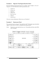
Connector Check
The Display unit has an LCD module, FL, panel close switch, and FL inverter board. The FL
and FL inverter board are connected by cable. The LCD module and system board are connected by signal cable as shown below. Any of these cables may be disconnected.
Disassemble the display unit and check the following cable connections. Refer to chapter 4.
Replacement Procedures, for more information about how to disassemble the computer.
Figure 2-3 Display connection
If any of these cables is not connected, firmly reconnect it and repeat Procedures 1 and 2. If
the problem still exists, perform Procedure 4.
Procedure 4
Replacement Check
The FL, FL inverter board, LCD module, and system board are connected to the display
circuits. Any of these components may be damaged. Refer to chapter 4, Replacement Procedures, for instructions on how to disassemble the computer and then perform the following
checks:
If the FL does not light, perform Check 1.
If characters are not displayed clearly, perform Check 3.
If some screen functions do not operate properly, perform Check 3.
If the FL remains lit when the display is closed, perform Check 4.
Check 1
2-26
Replace the FL unit with a new one and test the display again. If the problem still
exists, perform Check 2.
610CT
Check 2
Replace the FL inverter board with a new one and test the display again. If the
problem still exists, perform Check 3.
Check 3
Replace the LCD module with a new one and test the display again. If the
problem still exists, perform Check 4.
Check 4
Replace the panel sensor switch with a new one and test the display again. If the
problem still exists, perform Check 5.
Check 5
Replace the display cable with a new one and test the display again. If the
problem still exists, perform Check 6.
Check 6
The system board may be damaged. Replace the system board with a new one.
610CT
2-27
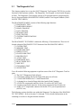
3.1
The Diagnostic Test
This chapter explains how to use the 610CT Diagnostic Test Program (TEST610) to test the
functions of the hardware modules. The Diagnostics Test Program is stored on the Diagnostic Disk. The Diagnostics Test Program consists of 20 programs that are grouped into the
Service Program Module (DIAGNOSTICS MENU) and the Test Program Module (DIAGNOSTIC TEST MENU).
The DIAGNOSTICS MENU consists of the following eight functions.
❑ DIAGNOSTIC TEST
❑ HARD DISK FORMAT
❑ HEAD CLEANING
❑ LOG UTILITIES
❑ RUNNING TEST
❑ FDD UTILITIES
❑ SYSTEM CONFIGURATION
❑ SETUP
The DIAGNOSTIC TEST MENU contains the following 12 functional tests. These are all
located within the DIAGNOSTIC TEST function of the DIAGNOSTICS MENU.
❑ SYSTEM TEST
❑ MEMORY TEST
❑ KEYBOARD TEST
❑ DISPLAY TEST
❑ FLOPPY DISK TEST
❑ PRINTER TEST
❑ ASYNC TEST
❑ HARD DISK TEST
❑ REAL TIMER TEST
❑ NDP TEST
❑ EXPANSION TEST
❑ SOUND TEST
You will need the following equipment to perform some of the 610CT Diagnostic Test Program.
❑ The 610CT Diagnostics Disk (all tests)
❑ A formatted working disk for the floppy disk drive test (all tests)
❑ 3.5-inch 2HD/2DD disk for 3.5-inch external FDD
❑ A cleaning kit to clean the floppy disk drive heads (Head Cleaning)
❑ A PCMCIA wraparound connector for the I/O card test (PCMCIA test)
❑ A printer wraparound connector for the printer wraparound test (Printer test)
❑ An RS-232-C wraparound connector for the RS-232-C port wraparound test
(ASYNC test)
The following sections detail the tests within the Diagnostic Test function of the DIAGNOSTIC TEST MENU. Refer to Sections 3.18 through 3.24 for detailed information on the
remaining seven Service Program Module functions.
610CT
3-1
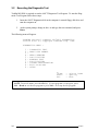
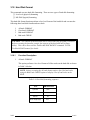
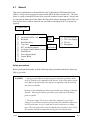
3.2
Executing the Diagnostic Test
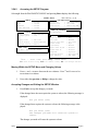
Toshiba MS-DOS is required to run the 610CT Diagnostic Test Program. To start the Diagnostic Test Program follow these steps:
1.
Insert the 610CT Diagnostics disk in the computer’s external floppy disk drive and
turn the computer on.
2.
At the system prompt, change to drive A and type the test command, and press
Enter.
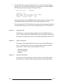
The following menu will appear:
TOSHIBA personal computer PT610CT DIAGNOSTICS
version X.XX (c) copyright TOSHIBA Corp. 19XX
DIAGNOSTICS MENU :
1
2
3
4
5
6
7
8
9
0
-
DIAGNOSTIC TEST
HARD DISK FORMAT
HEAD CLEANING
LOG UTILITIES
RUNNING TEST
FDD UTILITIES
SYSTEM CONFIGURATION
EXIT TO MS-DOS
SETUP
↑↓→←
Enter
Esc
:
:
:
Select items
Specify
Exit
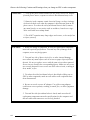
NOTE: To exit the menu, press the Esc key. If a test program is in progress, press
Ctrl + Break to exit the test program or press Ctrl + C to stop the test program.
3-2
610CT
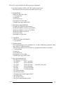
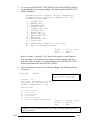
3.
To execute the DIAGNOSTIC TEST MENU from the DIAGNOSTICS MENU,
set the highlight bar to 1, and press Enter. The following DIAGNOSTIC TEST
MENU will appear:
TOSHIBA personal computer PT610CT DIAGNOSTICS
version X.XX (c) copyright TOSHIBA Corp. 19XX
DIAGNOSTIC TEST MENU :
1 - SYSTEM TEST
2 - MEMORY TEST
3 - KEYBOARD TEST
4 - DISPLAY TEST
5 - FLOPPY DISK TEST
6 - PRINTER TEST
7 - ASYNC TEST
8 - HARD DISK TEST
9 - REAL TIMER TEST
10 - NDP TEST
11 - EXPANSION TEST
12 - SOUND TEST
88 - ERROR RETRY COUNT SET [FDD & HDD]
99 - EXIT TO DIAGNOSTICS MENU
↑↓→←
Enter
Esc
:
:
:
Select items
Specify
Exit
Refer to sections 3.4 through 3.15 for detailed descriptions of each Diagnostic
Test, 1 through 12. Function 88 sets the floppy disk drive and hard disk drive
error retry count. Function 99 exits the submenus of the DIAGNOSTIC TEST
MENU and returns to the DIAGNOSTICS MENU.
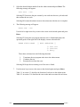
4.
Select the option you want to execute and press Enter. The following message
will appear:
SYSTEM TEST
XXXXXXX
PT610CT DIAGNOSTIC TEST VX.XX
[Ctrl]+[Break]; test end
[Ctrl]+[C]
; key stop
SUB-TEST : XX
PASS COUNT: XXXXX ERROR COUNT: XXXXX
WRITE DATA: XX READ DATA : XX
ADDRESS : XXXXXX STATUS : XXX
SUB-TEST MENU :
01
02
03
04
05
99
-
ROM checksum
HW status
Version check
Fan ON/OFF
Thermistor check
Exit to DIAGNOSTIC TEST MENU
↑↓→←
Enter
Esc
:
:
:
Select items
Specify
Exit
NOTE: The menu displayed by your 610CT may be slightly different from the
one shown above.
610CT
3-3
5.
Select the desired subtest number from the subtest menu and press Enter. The
following message will appear:
TEST LOOP
: YES
Selecting YES increases the pass counter by one each time the test cycle ends and
then restarts the test cycle.
Selecting NO returns the subtest menu to the main menu after the test is complete.
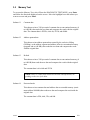
6.
The following message will appear:
ERROR STOP : YES
Use the left or right arrow keys to move the cursor to the desired option and press
Enter.
Selecting YES stops the test program when an error is found and displays the
operation guide on the right side of the display screen as shown below:
ERROR STATUS NAME
[[ HALT OPERATION ]]
1: Test end
2: Continue
3: Retry
These three selections have the following functions:
1:
2:
3:
Terminates the test program and exits to the subtest menu.
Continues the test.
Restarts the test from the error.
Selecting NO keeps the test running even if an error is found.
7.
Use the arrow keys to move the cursor to the desired option and press Enter.
Table 3-1 in section 3.3 describes the function of each test on the subtest menu.
Table 3-3 in section 3.16 describes the error codes and error status for each error.
3-4
610CT
3.3
Subtest Names
Table 3-1 lists the subtest names for each test program in the DIAGNOSTIC TEST MENU.
Table 3-1 Subtest names (1/2)
No.
1
610CT
Test name
SYSTEM
2
MEMORY
3
KEYBOARD
4
DISPLAY
5
FDD
6
PRINTER
Subtest No.
Subtest item
01
ROM checksum
02
03
04
05
01
02
03
04
05
06
01
02
03
04
01
02
03
04
05
06
07
08
09
10
11
H/W status
Version check
Fan on/off
Thermistor check
RAM constant data
RAM address pattern data
RAM refresh
Protected mode
Memory module
Cache memory
Pressed key display (82/84)
Pressed key code display
PS/2 Mouse connect check
Pointing Stick check
VRAM read/write
Character attributes
Character set
80*25/30 Character display
320*200 Graphics display
640*200 Graphics display
640*350/480 Graphics display
Display page
“H” pattern display/Border color
LED/DAC pallet
Color display
01
02
03
04
05
01
02
03
Sequential read
Sequential read/write
Random address/data
Write specified address
Read specified address
Ripple pattern
Function
Wrap around
3-5
Table 3-1 Subtest names (2/2)
No.
3-6
Test name
7
ASYNC
8
HDD
9
REAL TIMER
10
11
12
NDP
EXPANSION
SOUND
Subtest No.
01
02
03
04
05
01
02
03
04
05
06
07
08
09
10
01
02
03
01
01
01
02
03
Subtest item
Wrap around (board)
Board (#1) <=> board (#2)
Point to point (send)
Point to point (receive)
Interrupt test
Sequential read
Address uniqueness
Random address/data
Cross talk & peak shift
Write/read/compare (CE)
Write specified address
Read specified address
ECC circuit
Sequential write
W-R-C specified address
Real time
Backup memory
Real time carry
NDP test
PCMCIA wrap around
CODEC (REC/PLAY)
FM synthesizer
SINE wave playback
610CT
3.4
System Test
To execute the System Test select 1 from the DIAGNOSTIC TEST MENU, press Enter and
follow the directions displayed on the screen. Move the highlight bar to the subtest you want
to execute and press Enter.
Subtest 01
ROM checksum
The ROM checksum tests the system board from address F0000h to FFFFFh
(64KB).
Subtest 02
H/W status
This test reads and displays the hardware status as shown below:
CPU clock
Notch signal
=
=
90MHz [45MHz]
2HD [2DD]
Table 3-2 describes the hardware bit status for each bit tested. Pressing Enter
returns you to the Subtest Menu.
Table 3-2 Hardware Status
CPU clock speed
90 MHz
45 MHz
2HD
2DD
Media type
Subtest 03
Version check
This subtest checks the version of the following four items:
❑
❑
❑
❑
BIOS ROM
BOOT ROM
KBC version
PS microprocessor version
This subtest compares these four items to the reference data stored in the test
program. When the read information is lower than the reference data, the
speaker beeps, and the test program displays the following screen image. To
exit this screen, press the S key. When the read information is higher, the
display is unchanged.
ROM BIOS Version
BOOT ROM Version
KBC Version
PS Micom Version
=
=
=
=
V1.00
V1.00
V1.26
V1.35
:
:
:
:
OK
OK
NG
OK
V1.10
V1.00
V1.00
V1.35
Reference data
Current data
610CT
3-7
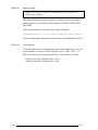
Subtest 04
Fan on/off
This subtest checks fan operation.
The fan cable is securely connected to PJ16 on the system board. When you
execute this subtest, the following message appears:
*** Fan ON *** : Press [Enter] key?
When you press Enter, the fan should spin.
*** Fan OFF *** : Press [Enter] key?
When you press Enter, the fan should stop.
Subtest 05
Thermistor check
This subtest checks the thermistor that controls CPU temperature. The thermistor cable connects to PJ23 on the system board.
3-8
610CT
3.5
Memory Test
To execute the Memory Test, select 2 from the DIAGNOSTIC TEST MENU, press Enter
and follow the directions displayed on the screen. Move the highlight bar to the subtest you
want to execute and press Enter.
Subtest 01
Constant data
This subtest writes a 256-byte unit of constant data to conventional memory (0
to 640 KB), then reads the new data and compares the result with the original
data. The constant data is FFFFh, AAAAh, 5555h, and 0000h.
Subtest 02
Address pattern data
This subtest writes address pattern data created by the exclusive-ORing
(XORing), to the address segment and address offset in conventional memory
(program end to 640 KB), then reads the new data and compares the result
with the original data.
Subtest 03
Refresh
This subtest writes a 256-byte unit of constant data to conventional memory (0
to 640 KB) then reads the new data and compares the result with the original
data.
The constant data is AAAAh and 5555h.
NOTE: There is a short delay between write and read operations, depending on the size of the data.
Subtest 04
Protected mode
This subtest writes constant data and address data to extended memory (maximum address 100000h) then reads new data and compares the result with the
original data.
The constant data is FFh, AAh, 55h, and 00h.
610CT
3-9
Subtest 05
Memory module
NOTE: To execute this subtest, an optional memory card must be installed in the computer.
This subtest functions the same as subtest 04, except it is used for testing an
optional memory card. Memory module capacity is 8 MB, 16 MB, 24 MB,
and 32 MB.
After selecting subtest 05, the following message will appear:
Extended memory size (1:8 MB,2:16 MB,3:24 MB,4:32 MB) ?
Select the number that corresponds to the memory card installed in the 610CT.
Subtest 06
Cache memory
To test the cache memory, a pass-through write-read comparison of ‘5A’ data
is run repeatedly to test area (‘7000’:’Program’ size to ‘7000’:=7FFF’ (32
KB)) to check the hit-miss ratio (on/off status). One test takes 3 seconds.
Number of miss hit < Number of hit → OK
Number of miss hit ≥ Number of hit → Fail
3-10
610CT
3.6
Keyboard Test
To execute the Keyboard Test, select 3 from the DIAGNOSTIC TEST MENU, press Enter
and follow the directions displayed on the screen. The Keyboard test contains four subtests
that test the 610CT keyboard actions. Move the highlight bar to the subtest you want to
execute and press Enter.
Subtest 01
Pressed key display (82/84)
NOTE: The Numeric and the Arrow modes must be off to execute this
subtest.
When you execute this subtest, the keyboard layout is drawn on the display as
shown below. When any key is pressed, the corresponding key on the screen
changes to an “*” character. Holding a key down enables the auto-repeat
function which causes the key’s display character to blink.
[[
Press Key Display
]]
If test OK, Press [Del] [Enter] Key
610CT
3-11
Subtest 02
Pressed key code display
When a key is pressed, the scan code, character code, and keytop name are
displayed on the screen in the format shown below. The Ins, Caps Lock,
Num Lock, Scroll Lock, Alt, Ctrl, Left Shift, and Right Shift keys are
displayed in reverse screen mode when pressed. The scan codes, character
codes, and keytop names are shown in Appendix D.
KEYBOARD TEST
IN PROGRESS
302000
Scan code
=
Character code =
Keytop
=
Ins Lock Caps Lock Num Lock Scroll Lock
Alt Ctrl Left Shift Right Shift
PRESS [Enter] KEY
Subtest 03
PS/2 mouse connect check
NOTE: To execute the PS/2 mouse connect check, a PS/2 mouse must be
connected to the optional port replicator.
This subtest checks whether a PS/2 mouse is connected.
If this test does not detect an error, it returns to the subtest menu.
If this test detects an error, the following message appears:
KBD - MOUSE INTERFACE ERROR
[[ HALT OPERATION ]]
1: Test end
2: Continue
3: Retry
3-12
610CT
Subtest 04
Ponting Stick Check
NOTE: To execute the pointing stick check, mouse driver software must
be installed.
This subtest checks the function of the pointing stick as shown below.
a) IPS stick pressure sensing direction and parameter.
b) IPS switch function check.
This test reports the pointing stick response from the IPS and IPS switch by
displaying the location parameters. When the stick is pressed towards the
upper left, the <POINTING> display changes to an arrow as shown below. If
an IPS switch is pressed, the <BUTTON> display alternates black and white
and appears on the right side of the display. If two IPS switches are pressed or
if this test does not detect an error, it returns to the subtest menu.
*****
<<
IPS TEST PROGRAM (V1.00)
*****
PRESS BUTTON1 + BUTTON2 THEN END
>>
When the button is pressed, it alternates as shown below.
610CT
3-13
3.7
Display Test
To execute the Display Test, select 4 from the DIAGNOSTIC TEST MENU, press Enter and
follow the directions displayed on the screen. The Display test contains eleven subtests that
test the 610CT display in various modes. Move the highlight bar to the subtest you want to
execute and press Enter.
Subtest 01
VRAM Read/Write
This subtest writes constant data FFFFh, AAAAh, 5555h, 0000h, and address
data to video RAM (1MB). This data is then read from the video RAM and
compared to the original data.
Subtest 02
Character Attributes
This subtest displays the following character attribute modes; normal, intensified, reverse, and blinking as shown in the display below. The character
attribute modes display the foreground color and intensified color (16 colors or
16-level gray scale) using black, blue, red, magenta, green, cyan, yellow, and
white from the color display. The display below appears on the screen when
this subtest is executed.
CHARACTER ATTRIBUTES
NEXT LINE SHOWS NORMAL DISPLAY.
NNNNNNNNNNNNNNNNNNNNNNNNNNNNNN
NEXT LINE SHOWS INTENSIFIED DISPLAY.
IIIIIIIIIIIIIIIIIIIIIIIIIIIIII
NEXT LINE SHOWS REVERSE DISPLAY.
RRRRRRRRRRRRRRRRRRRRRRRRRRRRRR
NEXT LINE SHOWS BLINKING DISPLAY
BBBBBBBBBBBBBBBBBBBBBBBBBBBBBB
00
01
04
05
02
03
06
07
08
09
0C
0D
0A
0B
0E
0F
;
;
;
;
;
;
;
;
BLACK
BLUE
RED
MAGENTA
GREEN
CYAN
YELLOW
WHITE
PRESS [Enter] KEY
3-14
610CT
After pressing Enter, 16 colors or 16 gray scales of mode 13h appear in the
320x200 graphics mode as shown below:
BLACK
BLUE
GREEN
CYAN
RED
MAGENTA
BROWN
WHITE
GRAY
LIGHT BLUE
LIGHT GREEN
LIGHT CYAN
LIGHT RED
LIGHT MAGENTA
YELLOW
INTENSE WHITE
Pressing Enter toggles between the two tests.
To exit this subtest and return to the DISPLAY TEST menu, press Ctrl +
Break.
Subtest 03
Character Set
In this subtest, the character set (addressed 00h to FFh) is displayed in the
40*25 character mode as shown below.
Press [Enter] KEY
To exit this subtest and return to the DISPLAY TEST menu, press Ctrl +
Break.
610CT
3-15
Subtest 04
80x25/30 Character Display (mode 3, 12)
In this subtest, the character string is displayed shifting one character to the
right, line by line in the 80x25 and 80x30 character modes as shown below.
80*XX CHARACTER DISPLAY
012345678901234567890123456789012345678901234567890123456789012345678901234567
!”#$%&’()*+,-./0123456789:;<=>?@ABCDEFGHIJKLMNOPQRSTUVWXYZ[\]^_‘abcdefghijklm
!”#$%&’()*+,-./0123456789:;<=>?@ABCDEFGHIJKLMNOPQRSTUVWXYZ[\]^_‘abcdefghijklmn
“#$%&’()*+,-./0123456789:;<=>?@ABCDEFGHIJKLMNOPQRSTUVWXYZ[\]^_`abcdefghijklmno
#$%&’()*+,-./0123456789:;<=>?@ABCDEFGHIJKLMNOPQRSTUVWXYZ[\]^_‘abcdefghijklmnop
$%&’()*+,-./0123456789:;<=>?@ABCDEFGHIJKLMNOPQRSTUVWXYZ[\]^_‘abcdefghijklmnopq
%&’()*+,-./0123456789:;<=>?@ABCDEFGHIJKLMNOPQRSTUVWXYZ[\]^_‘abcdefghijklmnopqr
&’()*+,-./0123456789:;<=>?@ABCDEFGHIJKLMNOPQRSTUVWXYZ[\]^_‘abcdefghijklmnopqrs
‘()*+,-./0123456789:;<=>?@ABCDEFGHIJKLMNOPQRSTUVWXYZ[\]^_`abcdefghijklmnopqrst
()*+,-./0123456789:;<=>?@ABCDEFGHIJKLMNOPQRSTUVWXYZ[\]^_‘abcdefghijklmnopqrstu
)*+,-./0123456789:;<=>?@ABCDEFGHIJKLMNOPQRSTUVWXYZ[\]^_‘abcdefghijklmnopqrstuv
*+,-./0123456789:;<=>?@ABCDEFGHIJKLMNOPQRSTUVWXYZ[\]^_‘abcdefghijklmnopqrstuvw
+,-./0123456789:;<=>?@ABCDEFGHIJKLMNOPQRSTUVWXYZ[\]^_‘abcdefghijklmnopqrstuvwx
,-./0123456789:;<=>?@ABCDEFGHIJKLMNOPQRSTUVWXYZ[\]^_‘abcdefghijklmnopqrstuvwxy
-./0123456789:;<=>?@ABCDEFGHIJKLMNOPQRSTUVWXYZ[\]^_‘abcdefghijklmnopqrstuvwxyz
./0123456789:;<=>?@ABCDEFGHIJKLMNOPQRSTUVWXYZ[\]^_‘abcdefghijklmnopqrstuvwxyz{
/0123456789:;<=>?@ABCDEFGHIJKLMNOPQRSTUVWXYZ[\]^_‘abcdefghijklmnopqrstuvwxyz{|
0123456789:;<=>?@ABCDEFGHIJKLMNOPQRSTUVWXYZ[\]^_‘abcdefghijklmnopqrstuvwxyz{|}
123456789:;<=>?@ABCDEFGHIJKLMNOPQRSTUVWXYZ[\]^_‘abcdefghijklmnopqrstuvwxyz{|}~
23456789:;<=>?@ABCDEFGHIJKLMNOPQRSTUVWXYZ[\]^_‘abcdefghijklmnopqrstuvwxyz{|}~•
3456789:;<=>?@ABCDEFGHIJKLMNOPQRSTUVWXYZ[\]^_‘abcdefghijklmnopqrstuvwxyz{|}~•Ç
456789:;<=>?@ABCDEFGHIJKLMNOPQRSTUVWXYZ[\]^_‘abcdefghijklmnopqrstuvwxyz{|}~•Çü
PRESS [ENTER] KEY
Pressing Enter toggles between tests. To exit this subtest and return to the
DISPLAY TEST menu, press Ctrl + Break.
Subtest 05
320x200 Character Display (mode 4,D)
This subtest displays two color sets for the color display in 320x200 dot
graphics mode 4 and D. One example is shown below:
GREEN
CYAN
RED
MAGENTA
BROWN
WHITE
Pressing Enter toggles between tests. To exit this subtest and return to the
DISPLAY TEST menu, press Ctrl + Break.
3-16
610CT
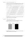
Subtest 06
640x200 Character Display (mode 6, E)
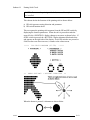
This subtest displays even dots, odd dots, and all dots in the 640x200 dot
graphics mode 6 and E as shown below:
To exit this subtest and return to the DISPLAY TEST menu, press Ctrl +
Break.
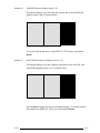
Subtest 07
640x350/480 Character Display (mode 10, 12)
This subtest displays even dots, odd dots, and all dots in the 640x350, and
640x480 dot graphics mode 10, 12 as shown below:
Pressing Enter changes the size of the displayed image. To exit this subtest
and return to the DISPLAY TEST menu, press Ctrl + Break.
610CT
3-17
Subtest 08
Display Page
This subtest confirms that the pages can be changed in order from page 0
through page 7 in 40*25 character mode.
DISPLAY PAGE 0
0000000000000000000000000000000000000000
0
0
0
0
0
0
0
0
0
0
0
0
0
0
0
0
0
0
0
0
0
0
0000000000000000000000000000000000000000
Pressing Ctrl + Break exits this subtest, after completion of the test, and
returns to the DISPLAY TEST menu.
Subtest 09
H Pattern Display/Border Color
This subtest displays 2000 H characters on the entire screen, as shown below.
HHHHHHHHHHHHHHHHHHHHHHHHHHHHHHHHHHHHHHHHHHHHHHHHHH
HHHHHHHHHHHHHHHHHHHHHHHHHHHHHHHHHHHHHHHHHHHHHHHHHH
HHHHHHHHHHHHHHHHHHHHHHHHHHHHHHHHHHHHHHHHHHHHHHHHHH
HHHHHHHHHHHHHHHHHHHHHHHHHHHHHHHHHHHHHHHHHHHHHHHHHH
HHHHHHHHHHHHHHHHHHHHHHHHHHHHHHHHHHHHHHHHHHHHHHHHHH
HHHHHHHHHHHHHHHHHHHHHHHHHHHHHHHHHHHHHHHHHHHHHHHHHH
HHHHHHHHHHHHHHHHHHHHHHHHHHHHHHHHHHHHHHHHHHHHHHHHHH
HHHHHHHHHHHHHHHHHHHHHHHHHHHHHHHHHHHHHHHHHHHHHHHHHH
HHHHHHHHHHHHHHHHHHHHHHHHHHHHHHHHHHHHHHHHHHHHHHHHHH
HHHHHHHHHHHHHHHHHHHHHHHHHHHHHHHHHHHHHHHHHHHHHHHHHH
HHHHHHHHHHHHHHHHHHHHHHHHHHHHHHHHHHHHHHHHHHHHHHHHHH
HHHHHHHHHHHHHHHHHHHHHHHHHHHHHHHHHHHHHHHHHHHHHHHHHH
HHHHHHHHHHHHHHHHHHHHHHHHHHHHHHHHHHHHHHHHHHHHHHHHHH
HHHHHHHHHHHHHHHHHHHHHHHHHHHHHHHHHHHHHHHHHHHHHHHHHH
Pressing Enter displays the following message:
Setting the color CRT (1:yes/2:no)
If an external CRT display is connected to the 610CT, choose 1 to display the
following message:
[Border color test (7 times press [Enter] key]
Press Enter to execute the border color test.
To exit this subtest and return to the DISPLAY TEST menu, press Ctrl +
Break.
3-18
610CT
Subtest 10
LED/DAC Pallet
This subtest checks the indicator icons (Caps Lock, Overlay and Num Lock)
by key operation.
[ Caps/Num/Overlay LED test ]
(1) Press [ Caps Lock
] key !...Caps (on/off)
(2) Press [ Fn + F10
] key !...Arrow (on/off)
(3) Press [ Fn + F11
] key !...Num
(on/off)
PRESS [Enter] KEY
Press Enter to display the following two messages:
After pressing Enter, it writes the ‘2A’ and ‘15’ data to 6 bit of 256x3 (RGB),
then reads new data and compares the result with original data.
[ DAC pallet W-R-CMP test ]
=
[ Processor latch test
=
]
(about 5 seconds)
Processor latch test (1:256 times, 2:endless) ?
To exit, press Ctrl + Break. Then press Enter.
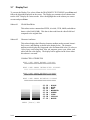
Subtest 11
Color display
This subtest sets the video mode to ‘13’, and displays color code (0 to 63) at
the same time, then displays seven screens. The first shows many colors at
once, the next three display 64 shades of red, green, and blue successively and
the last three display 64 shades of red, green and blue. Also, it sets the video
mode ‘5F’, and displays 256 colors.
Press Enter to change the display. Press Ctrl + Break to exit.
610CT
3-19
3.8
Floppy Disk Test
CAUTION: Before running the floppy disk test, prepare a formatted work disk.
Remove the Diagnostics Disk and insert a work disk into the FDD. The contents
of the floppy disk will be erased.
To execute the Floppy Disk Test, select 5 from the DIAGNOSTIC TEST MENU, press
Enter and follow the directions displayed on the screen. The Floppy Disk test contains five
subtests that test the 610CT external floppy disk drive. The following messages will appear
after selecting the Floppy Disk Test from the DIAGNOSTIC TEST MENU. Answer each
question with an appropriate response to execute the test.
1.
Select the test drive number of the floppy disk drive to be tested and press Enter.
Test drive number select (1:FDD#1,2:FDD#2,0:FDD1&2) ?
2.
Select the media type of the floppy disk in the test drive to be tested, and press
Enter.
Media in drive #X mode (0:2DD,1:2D,2:2D-2HD/2DD,3:2HD) ?
3.
Select the track you want the test to start on and press Enter. Simply pressing
Enter sets the start track to zero.
Test start track
4.
(Enter:0/dd:00-79) ?
The floppy disk test menu will appear after you select the start track number.
Select the number of the subtest you want to execute and press Enter. The
following message will appear during the floppy disk test.
FLOPPY DISK
XXXXXXX
PORTÉGÉ 610CT DIAGNOSTIC TEST VX.XX
[Ctrl]+[Break] ; test end
[Ctrl]+[C]
; key stop
SUB-TEST : XX
PASS COUNT: XXXXX ERROR COUNT: XXXXX
WRITE DATA: XX READ DATA : XX
ADDRESS : XXXXXX STATUS : XXX
The first three digits in the ADDRESS number indicate which cylinder is being
tested. The fourth digit indicates the head, and the last two digits indicate the
sector being tested.
The first digit in the STATUS number indicates the drive being tested and the last
two digits indicate the error status code as explained in table 3-3.
3-20
610CT
Subtest 01
Sequential Read
This subtest performs a Cyclic Redundancy Check (CRC), that continuously
reads all the tracks on a floppy disk. The following tracks are read according
to the media type in the floppy disk drive:
Double-sided, double-density (2D): Tracks 0 to 39.
Double-sided, double-density, double-track (2DD) and double-sided,
high-density, double-track (2HD): Tracks 0 to 79.
The start track is specified when the FDD test is started from the Diagnostic
Test Menu. Refer to step 3 at the beginning of this section to set the start
track.
Subtest 02
Sequential Read/Write
This subtest continuously writes data pattern B5ADADh to all the specified
tracks selected in step 3 above. The data is then read and compared to the
original data.
Subtest 03
Random Address/Data
This subtest writes random data to random addresses on all tracks defined in
step 3 above. The data is then read and compared to the original data.
Subtest 04
Write Specified Address
This subtest writes specified data to a specified track, head, and address.
Subtest 05
Read Specified Address
This subtest reads data from a specified track, head, and address.
610CT
3-21
3.9
Printer Test
To execute the Printer Test, select 6 from the DIAGNOSTIC TEST MENU, press Enter and
follow the directions displayed on the screen. The Printer Test contains three subtests that
test the output of the printer connected to the 610CT. The following messages will appear
after selecting the Printer Test from the DIAGNOSTIC TEST MENU. Answer each of the
following questions with an appropriate response to execute the test.
NOTE: An IBM compatible printer must be connected to the system to execute this
test.
channel#1 = XXXXh
channel#2 = XXXXh
channel#3 = XXXXh
Select the channel number (1-3) ?
The printer I/O port address is specified by the XXXXh number. The PORTÉGÉ 610CT
supports three printer channels. Select the printer channel number and press Enter to execute
the selected subtest.
Subtest 01
Ripple Pattern
This subtest prints characters for codes 20h through 7Eh line-by-line while
shifting one character to the left at the beginning of each new line.
!”#$%&’()*+,-./0123456789:;<=>?@ABCDEFGHIJKLMNOPQRSTUVWXYZ[\]^_‘abcdefghijklm
!”#$%&’()*+,-./0123456789:;<=>?@ABCDEFGHIJKLMNOPQRSTUVWXYZ[\]^_‘abcdefghijklmn
“#$%&’()*+,-./0123456789:;<=>?@ABCDEFGHIJKLMNOPQRSTUVWXYZ[\]^_`abcdefghijklmno
#$%&’()*+,-./0123456789:;<=>?@ABCDEFGHIJKLMNOPQRSTUVWXYZ[\]^_‘abcdefghijklmnop
$%&’()*+,-./0123456789:;<=>?@ABCDEFGHIJKLMNOPQRSTUVWXYZ[\]^_‘abcdefghijklmnopq
%&’()*+,-./0123456789:;<=>?@ABCDEFGHIJKLMNOPQRSTUVWXYZ[\]^_‘abcdefghijklmnopqr
&’()*+,-./0123456789:;<=>?@ABCDEFGHIJKLMNOPQRSTUVWXYZ[\]^_‘abcdefghijklmnopqrs
‘()*+,-./0123456789:;<=>?@ABCDEFGHIJKLMNOPQRSTUVWXYZ[\]^_`abcdefghijklmnopqrst
()*+,-./0123456789:;<=>?@ABCDEFGHIJKLMNOPQRSTUVWXYZ[\]^_‘abcdefghijklmnopqrstu
)*+,-./0123456789:;<=>?@ABCDEFGHIJKLMNOPQRSTUVWXYZ[\]^_‘abcdefghijklmnopqrstuv
*+,-./0123456789:;<=>?@ABCDEFGHIJKLMNOPQRSTUVWXYZ[\]^_‘abcdefghijklmnopqrstuvw
3-22
610CT
Subtest 02
Function
This subtest is for IBM compatible printers, and tests the following functions:
Normal print
Double width print
Compressed print
Emphasized print
Double strike print
All characters print
This subtest prints the various print types shown below:
PRINTER TEST
1.
THIS LINE SHOWS NORMAL PRINT.
2.
THIS LINE SHOWS DOUBLE-WIDTH PRINT.
3.
THIS LINE SHOWS COMPRESSED PRINT.
4.
THIS LINE SHOWS EMPHASIZED PRINT.
5.
THIS LINE SHOWS DOUBLE-STRIKE PRINT.
6.
ALL CHARACTERS PRINT
!"#$%&'()*+,./0123456789:;<=>?@ABCDEFGHIJKLMNOPQRSTUVWXYZ[\]^_`abcdefghijklmn
opqrstuvwxyz{|}~
Subtest 03
Wraparound
NOTE: To execute this subtest, a printer wraparound connector must be
connected to the computer’s printer port. The printer wraparound connector (34M741986G01) wiring diagram is described in Appendix G.
This subtest checks the output and bidirectional modes of the data control and
status lines through the printer wraparound connector.
610CT
3-23
3.10 Async Test
To execute the Async Test, select 7 from the DIAGNOSTIC TEST MENU, press Enter and
follow the directions displayed on the screen. The async test contains five subtests that test
the 610CT asynchronous communication functions. Move the highlight bar to the subtest you
want to execute and press Enter.
Subtests 01 through 04 require the following data format:
Method:
Speed:
Data:
Data pattern:
Asynchronous
9600BPS
8 bits and one parity bit (EVEN)
20h to 7Eh
The following message will appear at the bottom of the screen when subtests 01, 03, 04, and
05 are selected:
Channel#1 = XXXXh
Channel#2 = XXXXh
Channel#3 = XXXXh
Select the Channel number (1 - 3)
The serial I/O port address is specified by the XXXXh number. Select the serial port channel
number, and press Enter to start the subtest.
Subtest 01
Wraparound (board)
NOTE: To execute this subtest an RS-232-C wraparound connector
(34M741621G01) must be connected to the RS-232-C port. The RS-232-C
wraparound connector wiring diagram is described in Appendix G.
This subtest checks the data send/receive function through the wraparound
connector.
Subtest 02
Board (#1) <=> board (#2)
NOTE: To execute this subtest, an RS-232-C cable (9-pin to 9-pin) must
be connected to boards 1 and 2. The RS-232-C direct cable wiring diagram is described in Appendix G.
This subtest checks the data send/receive function through the RS-232-C
direct cable.
3-24
610CT
Subtest 03
Point to point (Send)
NOTE: To execute this subtest, two machines must be connected with an
RS-232-C direct cable. One machine should be set as “send” (subtest
03) and the other set as “receive” (subtest 04). The wiring diagram for
the RS-232-C direct cable is described in Appendix F.
This subtest sends 20h through 7Eh data to the receive side, then receives the
sent data and compares it to the original data.
Subtest 04
Point to point (Receive)
This subtest is used with subtest 03 described above. This subtest receives the
data from the send side, then sends the received data.
Subtest 05
Interrupt Test
This subtest checks the Interrupt Request Level of IRQ 4, 3, and 5 from the
send side.
610CT
3-25
3.11 Hard Disk Test
To execute the Hard Disk Test, select 8 from the DIAGNOSTIC TEST MENU. Press
Enter, and follow the directions displayed on the screen. The hard disk test contains 10
subtests that test the 610CT hard disk drive functions. The following messages will appear
after selecting the hard disk test from the DIAGNOSTIC TEST MENU. Answer each of the
following questions with an appropriate response to execute the test:
CAUTION: The contents of the hard disk will be erased when subtest 02, 03, 04, 05, 06,
08, 09, or 10 is executed. Before running the test, transfer the contents of the hard disk
to a floppy disk(s). This can be done with the Toshiba MS-DOS BACKUP command.
After the hard disk test is completed, execute the Toshiba MS-DOS FDISK command,
which will set the partition. Next, execute the Toshiba MS-DOS FORMAT command.
Refer to the Toshiba MS-DOS manual for details.
1.
When you select the hard disk test from the DIAGNOSTIC TEST MENU, the
following message will appear:
Test drive number select (1:HDD#1,2:HDD#2,0:HDD1&2) ?
2.
Select the hard disk drive number to be tested and press Enter. The following
message will appear:
HDC F/W error retry
3.
(1:yes,2:no) ?
This message is used to select the retry operation when the hard disk controller
detects an error. Select 1 or 2 and press Enter. The following message will
appear:
Data compare error dump (1:no,2:yes) ?
4.
This message is used to select the error dump operation when a data compare
error is detected. Select 1 or 2 and press Enter. The following message will
appear:
Detail status display (1:no,2:yes) ?
5.
3-26
This message is used to select whether or not the HDD status is displayed on the
screen. The HDD status is described in section 3.15. Select 1 or 2 and press
Enter.
610CT
6.
The Hard Disk Test message will appear after you respond to the Detail Status
prompt. Select the number of the subtest you want to execute and press Enter.
The following message will appear during each subtest.
HARD DISK TEST
XXXXXXX
SUB-TEST : XX
PASS COUNT: XXXXX ERROR COUNT: XXXXX
WRITE DATA: XX READ DATA : XX
ADDRESS : XXXXXX STATUS : XXX
The first three digits of the ADDRESS indicate which cylinder is being tested, the
fourth digit indicates the head and the last two digits indicate the sector.
The first digit of the STATUS number indicates the drive being tested and the last
two digits indicate the error status code as explained in table 3-3 in Section 3.16.
Subtest 01
Sequential Read
This subtest is a sequential reading of all the tracks on the HDD starting at
track 0. When all the tracks on the HDD have been read, the test starts at the
maximum track and reads the tracks on the HDD sequentially back to track 0.
Subtest 02
Address Uniqueness
This subtest writes unique address data to each sector of the HDD track-bytrack. The data written to each sector is then read and compared with the
original data. There are three ways the HDD can be read:
• Forward sequential
• Reverse sequential
• Random
Subtest 03
Random Address/Data
This subtest writes random data to random addresses on the HDD cylinder,
head and sector. This data is then read and compared to the original data.
610CT
3-27
Subtest 04
Cross Talk & Peak Shift
This subtest writes eight types of worst pattern data (shown below) to a
cylinder, then reads the data while moving from cylinder to cylinder.
Subtest 05
Worst pattern data
Cylinder
‘B5ADAD’
0 cylinder
‘4A5252’
1 cylinder
‘EB6DB6’
2 cylinder
‘149249’
3 cylinder
’63B63B’
4 cylinder
‘9C49C4’
5 cylinder
‘2DB6DB’
6 cylinder
‘D24924’
7 cylinder
Write /read/compare (CE)
This subtest writes B5ADADh worst pattern data to the CE cylinder on the
HDD, then reads the data from the CE cylinder and compares it with the
original data.
Subtest 06
Write specified address
This subtest writes specified data to a specified cylinder and head on the HDD.
Subtest 07
Read specified address
This subtest reads data which has been written to a specified cylinder and head
on the HDD.
Subtest 08
ECC circuit
This subtest checks the Error Check and Correction (ECC) circuit functions of
the specified cylinder and head on the HDD.
Subtest 09
Sequential write
This subtest writes specified 2-byte data to all of the cylinders on the HDD.
Subtest 10
W-R-C specified address
This subtest writes data to a specified cylinder and head on the HDD, then
reads the data and compares it to the original data.
3-28
610CT
3.12 Real Timer Test
To execute the Real Timer Test, select 9 from the DIAGNOSTIC TEST MENU, press Enter
and follow the directions on the screen. The real timer test contains three subtests that test
the 610CT real timer functions. Move the highlight bar to the subtest you want to execute
and press Enter.
Subtest 01
Real Time
A new date and time can be input during this subtest. To execute the real time
subtest follow these steps:
1. Select subtest 01 and the following message will appear:
Current date : XX-XX-XXXX
Current time : XX:XX:XX
Enter new date:
PRESS [ENTER] KEY TO EXIT TEST
2. If the current date is not correct, input the correct date at the “Enter new
date” prompt and press Enter. The following prompt will appear:
Enter new time :
3. If the current time is not correct, input the correct time in 24-hour format.
Pressing Enter toggles between the time and the date. To exit, press Ctrl
+ Break.
Subtest 02
Backup Memory
This subtest performs the following backup memory check:
Writes 1-bit of “on” data to address 01h through 80h
Writes 1-bit of “off” data to address FEh through 7Fh
Writes the data pattern AAh through 55h to the RTC 50-byte memory
(address 0Eh to 3Fh)
The subtest then reads and compares this data with the original data.
To exit, press Ctrl + Break.
610CT
3-29
Subtest 03
Real Time Carry
CAUTION: When this subtest is executed, the current date and time are
erased.
This subtest checks the real time clock increments, making sure the date and
time are displayed in the following format:
Current date : 12-31-1994
Current time : 23:59:58
Pressing Enter displays the following:
Current date : 01-01-1995
Current time : 00:00:00
PRESS [Enter] KEY TO EXIT TEST
Press Ctrl + Break to exit.
3-30
610CT
3.13 NDP Test
To execute the NDP test, select 10 from the DIAGNOSTICS TEST MENU, press Enter and
follow the directions on the screen. The NDP test contains one subtest that tests the 610CT
NDP functions.
Subtest 01
NDP
This test checks the following NDP functions:
❑
❑
❑
❑
❑
Control word
Status word
Bus
Addition
Multiplication
Press Ctrl + Break to exit.
610CT
3-31
3.14 Expansion Test
NOTE: To execute this subtest, the PCMCIA wraparound card is required.
Subtest 01
PCMCIA wraparound test
This test checks the following signal lines of the PCMCIA slot:
❑
❑
❑
❑
❑
❑
Address line
REG#, CE#1, CE#2 line
Data line
Speaker line
Wait line
BSY#, BVD1 line
This subtest is executed in the following order:
3-32
Sub#
Address
Good
Bad
Contents
01
00001
00001
nn
nn
xx
xx
Address line
REG#, CE#1, CE#2
nn=A0, 90, 80, 00
02
00002
ww
rr
Data line
ww=write data, rr=read data
03
00003
––
––
Speaker line
04
00004
40, 80
xx
Wait line (40<xx<80)
05
00005
nn
xx
Other lines (BSY#, BVD1)
nn=21, 00
610CT
3.15 Sound Test
To execute the Sound test, select 12 from the DIAGNOSTICS TEST MENU, press Enter
and follow the directions on the screen. The Sound test contains three subtests that test the
610CT series Sound functions.
Subtest 01
CODEC (REC/PLAY)
NOTE: To execute this subtest, the internal microphone and internal
headphone (or internal speaker) are required.
Tests the functions of the Codec (ES688) A/D, D/A converter. At the same
time, tests the microphone and headphone terminals. When you execute this
subtest, the following message is displayed:
[Quick REC & PLAY for ES488/688]
Press any key to *** REC ***
After pressing any key, start the recording and immediately play the sound. (It
takes three seconds.)
Subtest 02
FM synthesizer
Tests the OPL# (YMF262) functions. Connect the headphone and check the
scale for the right and left sides. Also check the sound adjustment volume.
Subtest 03
SINE wave playback
This subtest expands the sine wave data table to 64KB and creates sine wave
data. The play data is transferred between DMA and CODEC, and plays the
sound. (It is a long beep.) Also, using the oscilloscope, observe the sine
waveform.
610CT
3-33
3.16 Error Code and Error Status Names
Table 3-3 lists the error codes and error status names for the Diagnostic Test.
Table 3-3 Error codes and error status names (1/2)
Device name
Error status name
(COMMON)
FF
Data Compare Error
System
01
ROM Checksum Error
Memory
01
02
Parity Error
Protected Mode Not Changed
14
DD
Memory Read/Write Error
Cache Memory Error
01
Mouse Interface Error
02
IPS Interface Error
03
Interface Error
04
Retransmit Error
05
06
Mouse Handler Not Supported
PS/2 Mouse & IPS Not
01
Bad Command
02
03
Address Mark Not Found
Write Protected
04
06
Record Not Found
Media Removed
08
09
DMA Overrun Error
DMA Boundary Error
10
20
CRC Error
FDC Error
40
60
Seek Error
FDD Not Drive Error
80
EE
Time Out Error
Write Buffer Error
01
08
Time Out
Fault
10
20
Select Line
Out Of Paper
40
80
Power Off
Busy Line
01
DSR On Time Out
02
CTS On Time Out
04
RX-READY Time Out
08
TX-BUFFER Full Time Out
Keyboard
FDD
Printer
Async
3-34
Error code
610CT
Table 3-3 Error codes and error status names (2/2)
Device name
Error code
Async (cont.)
10
Parity Error
20
40
Framing Error
Overrun Error
80
88
Line Status Error
Modem Status Error
33
34
No Carrier (Card Modem)
Error (Card Modem)
36
No Dial Tone (Card Modem)
01
02
Bad Command Error
Bad Address Mark Error
04
05
Record Not Found
HDC Not Reset Error
07
08
Drive Not Initialized
HDC Overrun (DRQ)
09
0A
DMA Boundary Error
Bad Sector
0B
10
Bad Track Error
ECC Error
11
20
ECC Recover Enabled
HDC Error
40
80
Seek Error
Time Out Error
AA
BB
Drive Not Ready
Undefined Error
CC
E0
Write Fault
Status Error
EE
Access Time Out Error
01
02
No Co-Processor
Control Word Error
03
04
Status Word Error
Bus Error
05
06
Addition Error
Multiply Error
C1
Address Line Error
C2
C3
REG# Line Error
CE#1 Line Error
C4
C5
CE#2 Line Error
DATA Line Error
C6
C7
WAIT Line Error
BSY# Line Error
C8
CD
BVD1 Line Error
No PCMCIA
HDD
NDP
PCMCIA
610CT
Error status name
3-35
3.17 Hard Disk Test Detail Status
When an error occurs in the hard disk test, the following message is displayed:
HDC status = XXXXXXXX
Detailed information about the hard disk test error is displayed on the screen by an eight-digit
number. The first four digits represent the hard disk controller (HDC) error status number.
The last four digits are not used.
The hard disk controller error status is composed of 2 bytes; the first byte displays the contents of the HDC status register in hexadecimal form and the second byte displays the HDC
error register.
The contents of the HDC status register and error register are listed in tables 3-4 and 3-5.
Table 3-4 Hard disk controller status register contents
Bit
Name
Description
7
BSY
(Busy)
“0” --- HDC is busy.
“1” --- HDC is ready.
6
DRDY
(Drive ready)
“0” --- Hard disk drive is not ready to accept any command.
“1” --- Hard disk drive is ready.
5
DWF
“0” --- DWF error is not detected.
(Drive write fault)
“1” --- Write fault condition occurred.
DSC
(Drive seek
“0” --- The hard disk drive heads are not settled over a track.
“1” --- The hard disk drive heads are settled over a track.
4
complete)
3-36
3
DRQ
(Data request)
“0” --- Drive is not ready for data transfer.
“1” --- Drive is ready for data transfer.
2
CORR
“0” --- Other
(Corrected data)
“1” --- Correctable data error is corrected.
1
IDX
(Index)
“0” --- Other
“1” --- Index is sensed.
0
ERR
(Error)
“0” --- Other
“1” --- The previous command was terminated with some error.
610CT
Table 3-5 Error register contents
Bit
7
Name
BBK1
(Bad block
Description
“0” Other
“1” A bad block mark is detected.
mark)
6
UNC
“0” There is no uncorrectable data error.
(Uncorrectable)
“1” Uncorrectable data error has been detected.
5
——
Not used.
4
IDNF
“0” Other
(Identification)
“1” There was no ID field in the requested sector.
3
——
Not used
2
ABRT
(Abort)
“0” Other
“1” Illegal command error or a drive status error occurred.
1
TK00
“0” The hard disk has found track 0 during a recalibrate command.
(Track 0)
“1” The hard disk could not find track 0 during a recalibrate command.
——
Not used.
0
610CT
3-37
3.18 Hard Disk Format
This command executes hard disk formatting. There are two types of hard-disk formatting:
❑ Low-level (physical) formatting
❑ MS-DOS (logical) formatting
This hard disk format function performs a low-level format of the hard disk and executes the
following three hard disk formats and one check:
1.
2.
3.
4.
All track FORMAT
Good track FORMAT
Bad track FORMAT
Bad track CHECK
CAUTION: The contents of the hard disk will be erased when this program is executed.
Before executing the function, transfer the contents of the hard disk onto a floppy
disk(s). This can be done with the Toshiba MS-DOS BACKUP command. See the
Toshiba MS-DOS manual for details.
3.18.1
1.
Function Description
All track FORMAT
This option performs a low-level format of all the tracks on the hard disk as shown
in Table 3-6 below:
NOTE: Before executing the all track format option, check for bad tracks
using the Bad Track CHECK option or display a list of bad tracks on the
HDD.
Table 3-6 Hard disk formatting sequence
Items
3-38
IBM DBOA-2720
Cylinders
1,400
Heads
16
Sectors
63
Sector length (bps)
512
610CT
2.
Good track FORMAT
This option formats a specified cylinder and track as a good track. If a good track
is formatted as a bad track, use this option to change the track to a good track.
3.
Bad track FORMAT
This option formats a specified cylinder and track as a bad track. If a bad track is
detected, use this option to label it as a bad track.
4.
Bad track CHECK
This option searches the hard disk for bad tracks by reading data to all the tracks
on the hard disk. A list of bad tracks is displayed when the program is complete.
If an error other than a bad track is detected, the program is automatically terminated.
3.18.2
Operations
CAUTION: After the HDD has been formatted, execute the Toshiba MS-DOS FDISK
command to partition the HDD. Next, execute the Toshiba MS-DOS FORMAT command. Refer to the Toshiba MS-DOS manual for more information about using these
commands.
Selecting TEST 2 and pressing Enter in the DIAGNOSTIC MENU displays the following
messages:
DIAGNOSTICS - HARD DISK FORMAT : VX.XX
1
2
3
4
9
-
All track FORMAT
Good track FORMAT
Bad track FORMAT
Bad track CHECK
Go to TEST MENU
↑↓→← : Select items, Enter: Finish, Esc: Exit
1. All track FORMAT
Pressing 1 selects All track FORMAT, which lets you format the entire disk.
[All track FORMAT]
Drive
:
Cylinder :
Head
:
Sector :
#1 = HDD
XXXX
XX
XX
<<< Model name =
610CT
#2 = Non
>>>
3-39
The following selections also appear at the bottom of the screen in
succession:
Drive number select (1:#1,2:#2) ?
(a)
Select a drive number and press Enter. The following message will appear:
Interleave number (1/1 ~ 8) ?
(b)
Select an interleave number, 1 ~ 8 and press Enter. Pressing only Enter
selects 1.
Unlock format select (1:no/2:yes)
(c)
Select whether the disk has an unlock format.
NOTE: This option appears only when an HDD manufactured by JVC
is installed. For JVC HDDs, which are the only disks with unlock
formats, you must select 2 (yes). If 1 is selected with a JVC disk, an
error will be generated. The system defaults to 1 and this message does
not appear when other disks are installed.
(d)
Bad track register
Next, the Bad Track register prompt will appear as shown below. Enter the
cylinder and head numbers of bad tracks and press Enter. Note that if there
are no bad tracks, pressing Enter alone is the same as executing All Track
Format described in item (e) below.
[ WARNING : Current DISK data will be
completely destroyed ]
Press Bad cylinder number (dddd)] key ?
Press Bad head number (dd)] key ?
Enter the cylinder and head number in the format above in decimal notation.
Repeat for each bad track you want to format.
After entering the bad tracks, press Enter to execute the format.
(e)
All track format
All tracks are formatted as good tracks except those registered as bad tracks
in item (d) above or those identified as bad tracks in track verification described in item (f) below.
(f)
Track verification
A check is made of all tracks and if an ECC error, ECC-correctable-data
error, or record-not-found error is detected at a track, that track is automatically formatted as a bad track.
3-40
610CT
2.
Good track FORMAT
If a good track has been erroneously formatted as a bad track, you can use this
subtest to reformat the track as a good track. To format a track as a good track,
enter the numbers for the drive, interleave, cylinder, and head as indicated in the
screen prompt shown below.
Drive number select (1:#1, 2:#2) ?
Interleave number (1 / 1 - 8) ?
Press [Cylinder number (dddd)] ?
Press [Head number (dd)] ?
Press Enter to return to the Hard Disk Format menu.
3.
Bad track FORMAT
To format a track as a bad track, enter the numbers for the drive, interleave,
cylinder, and head as indicated in the screen prompt shown below.
Drive number select (1:#1, 2:#2) ?
Interleave number (1 / 1 - 8) ?
Press [Cylinder number (dddd)] ?
Press [Head number (dd)] ?
Press Enter to return to the Hard Disk Format menu.
4.
Bad track CHECK
This subtest reads the entire disk and displays a list of bad tracks. The test is
terminated in case of a bad track check error. To initiate the subtest enter the
drive number at the prompt shown below.
Drive number select (1:#1, 2:#2) ?
Bad tracks will be displayed in the format shown below.
[[cylinder, head = 0123 03]]
Press Enter to return to the Hard Disk Format menu.
610CT
3-41
3.19 Head Cleaning
3.19.1
Function Description
This function cleans the heads in the FDD by executing a series of head load/seek and read
operations. A cleaning kit is necessary to perform this program.
3.19.2
1.
Operations
Selecting test 4 from the DIAGNOSTIC MENU and pressing Enter displays the
following messages:
DIAGNOSTICS - FLOPPY DISK HEAD CLEANING : VX.XX
Mount cleaning disk(s) on drive(s).
Press any key when ready.
3-42
2.
Remove the Diagnostics Disk from the FDD, then insert the cleaning disk and
press Enter.
3.
When the cleaning start message appears, the FDD head cleaning has begun.
4.
The display automatically returns to the DIAGNOSTIC MENU when the program
is completed.
610CT
3.20 Log Utilities
3.20.1
Function Description
This function logs error information generated while a test is in progress and stores the results
in RAM. This function can store data on a floppy disk or output the data to a printer. If the
power switch is turned off, the error information will be lost. The error information is displayed in the following order:
1.
2.
3.
4.
5.
6.
7.
8.
9.
10.
3.20.2
1.
Error count (CNT)
Test name (TS-NAME)
Subtest number (TS-NAME)
Pass count (PASS)
Error status (STS)
FDD/HDD or memory address (ADDR)
Write data (WD)
Read data (RD)
HDC status (HSTS)
Error status name ( ERROR STATUS NAME)
Operations
Selecting 5 and pressing Enter in the DIAGNOSTIC MENU logs error information into RAM or onto a floppy disk. The error information is displayed in the
following format:
XXXXX ERRORS
CNT TS-NAME PASS STS ADDR
WD RD HSTS [STATUS NAME]
001 FDD 02 0000
001 FDD 01 0000
00 00
00 00
103 00001
180 00001
FDD - WRITE PROTECTED
FDD - TIME OUT ERROR
Address
Error status
Pass count
HDC status
Subtest number
Read data
Test name
Write data
Error count
Error status name
[[1:Next,2:Prev,3:Exit,4:Clear,5:Print,6:FD Log Read,7:FD Log Write]]
610CT
3-43
2.
The error information displayed on the screen can be manipulated by the following
number keys:
The 1 key scrolls the display to the next page.
The 2 key scrolls the display to the previous page.
The 3 key returns to the Diagnostic Menu.
The 4 key erases all error log information in RAM.
The 5 key outputs the error log information to a printer.
The 6 key reads the log information from a floppy disk.
The 7 key writes the log information to a floppy disk.
3.
3-44
In the case of “error retry OK,” a capital “R” will be placed at the beginning of the
error status. However, it is not added to the error count.
610CT
3.21 Running Test
3.21.1
Function Description
This function automatically executes the following tests in sequence:
1.
2.
3.
4.
5.
6.
7.
8.
System test (subtest number 01)
Memory test (subtest number 01, 02, 04, 06, 07)
Display test (subtest number 01 to 08)
FDD test (subtest number 02)
HDD test (subtest number 01, 05)
Real timer test (subtest number 02)
Printer test (subtest number 03)
Async test (subtest number 01)
The system automatically detects the number of floppy disk drives connected to the 610CT
for the FDD test.
3.21.2
Operations
CAUTION: Do not forget to load a work disk in the FDD. If a work disk is not
loaded, an error will be generated during the FDD testing.
1.
Remove the diagnostics disk from the floppy disk drive and insert the work disk.
2.
Select 6 from the Diagnostic Menu and press Enter, the following message will be
displayed:
Printer wrap around test (Y/N) ?
Selecting Y (yes) executes the printer wraparound test. A printer wraparound
connector must be connected to the PRT port on the back of the 610CT to properly execute this test.
3.
Select Y or N and press Enter. The following message will appear:
Serial #A wrap around test (Y/N) ?
Selecting Y (yes) executes the ASYNC wraparound test. An RS-232-C wraparound connector must be connected to the serial port on the back of the 610CT
to properly execute this test.
610CT
3-45
4.
Select Yes or No and press Enter. The following message will appear :
Mount the work disk(s) on the drive(s),
then press [Enter] key.
[Warning : The contents of the disk(s),
will be destroyed]
5.
3-46
This program is executed continuously. To terminate the program, press Ctrl +
Break.
610CT
3.22 Floppy Disk Drive Utilities
3.22.1
Function Description
This function formats the FDD, copies the floppy disk, and displays the dump list for both the
FDD and HDD.
1.
FORMAT
NOTE: This program is only for testing a floppy disk drive. The option is
different from the Toshiba MS-DOS FORMAT command.
This program can format a 3.5-inch floppy disk in the following formats:
2.
(a)
2D: Double-sided, double-density, 48/67.5 TPI, MFM mode, 512 bytes, 9
sectors/track.
(b)
2DD: Double-sided, double-density, double-track, 96/135 TPI, MFM mode,
512 bytes, 9 sectors/track.
(c)
2HD: Double-sided, high-density, double-track, 96/135 TPI, MFM mode,
512 bytes, 18 sectors/track.
COPY
This program copies data from a source floppy disk to a target floppy disk.
3.
DUMP
This program displays the contents of the 3.5-inch floppy disk and the designated
sectors of the hard disk on the display.
3.22.2
1.
Operations
Selecting 7 from the DIAGNOSTIC MENU and pressing Enter displays the
following message:
[ FDD UTILITIES ]
1
2
3
9
610CT
-
FORMAT
COPY
DUMP
EXIT TO DIAGNOSTICS MENU
3-47
2.
FORMAT program
(a)
Selecting FORMAT displays the following message:
DIAGNOSTICS - FLOPPY DISK FORMAT : VX.XX
Drive number select (1:A, 2:B) ?
(b)
Select a drive number to display the following message:
Type select (0:2DD-2DD,1:2D-2D,2:2D-2HD,3:2HD-2HD) ?
(c)
Select a media/drive type number and press Enter. A message similar to the
one below will be displayed:
Warning : Disk data will be destroyed.
Insert work disk into drive A:
Press any key when ready.
(d)
Remove the Diagnostics Disk from the FDD, insert the work disk and press
any key.
The following message will be displayed when the FDD format is executed:
[ FDD TYPE ] : TRACK = XXX
[ FDD TYPE ] : HEAD
= X
[ FDD TYPE ] : SECTOR = XX
Format start
[[track, head = XXX X]]
After the floppy disk is formatted, the following message will appear:
Format complete
Another format (1:Yes/2:No) ?
(e)
3.
Typing 1 displays the message from step (c) above. Typing 2 returns the test
to the DIAGNOSTIC MENU.
COPY program
(a)
When COPY is selected, the following message appears:
FLOPPY DISK FORMAT & COPY : VX.XX
Type select (0:2DD-2DD,1:2D-2D,2:2D-2HD,3:2HD-2HD) ?
(b)
Selecting a media/drive type number will display a message similar to the one
below:
Insert source disk into drive A:
Press any key when ready.
3-48
610CT
(c)
Remove the Diagnostics Disk from the FDD, insert the source disk, and
press any key. The following message will appear, indicating the program
has started.
[ FDD TYPE ] : TRACK = XXX
[ FDD TYPE ] : HEAD
= X
[ FDD TYPE ] : SECTOR = XX
Copy start
[[ track,head
(d)
=
XXX X ]]
Remove the source disk from the FDD, insert a formatted work disk, and
press any key. The [[ track, head = XXX X ]] message will appear and
start copying to the target disk. When the amount of data is too large to be
copied in one operation, the message from step (b) is displayed again. After
the floppy disk has been copied, the following message will appear:
Copy complete
Another copy (1:Yes/2:No) ?
(e)
4.
To copy another disk, type 1 and the message from step (a) will be displayed
again. Entering 2 returns the test program to the DIAGNOSTIC MENU.
DUMP program
(a)
When dump is selected, the following message appears:
DIAGNOSTICS-HARD DISK & FLOPPY DISK DUMP : VX.XX
Drive type select (1:FDD, 2:HDD) ?
(b)
Select a format type number. If 2 is selected, the display will go to step (e).
Select FDD number (1:A, 2:B) ?
(c)
Select a drive number and the following message will be displayed:
Format type select (0:2DD, 1:2D, 2:2HD) ?
(d)
Select a media type number and the following message will appear:
Insert source disk into drive A:
Press any key when ready.
(e)
Insert a source disk and press any key and the following message will appear:
—— Max. address
[Track ] =
[ Head ] =
[Sector] =
Track
(f)
610CT
——
0079
01
09
number ??
Set the track number you want to dump. The system will access the disk and
dump a list.
3-49
3.23 System Configuration
3.23.1
Function Description
The System Configuration program contains the following configuration information for the
610CT:
1.
2.
3.
4.
5.
6.
7.
8.
9.
10.
11.
12.
3.23.2
BIOS ROM version
Boot ROM version
KBC version
PS Micom Version
Base memory size
The number of floppy disk drives
The number of ASYNC ports
The number of hard disk drives
The number of printer ports
Extended Memory Size
CPU type
The number of Co-processors
Operations
Selecting 8 from the DIAGNOSTIC MENU and pressing Enter displays the following system
configuration:
SYSTEM CONFIGURATION :
*
*
*
*
-
BIOS ROM VERSION = VX.XX
BOOT ROM VERSION = VX.XX
KBC VERSION
= VX.XX
PS MICOM VERSION = VX.XX
*
*
*
*
*
*
*
*
*
-
1 MATH CO-PROCESSOR
639KB MEMORY
XXXXXKB EXTENDED MEMORY
1 FLOPPY DISK DRIVE(S)
1 ASYNC ADAPTER
1 HARD DISK DRIVE(S)
1 PRINTER ADAPTER
2 PCMCIA SLOTS
1 SOUND SYSTEM
Press [Enter] Key
Press Enter to return to the DIAGNOSTIC MENU.
3-50
610CT
3.24 SETUP
3.24.1
Function Description
This program displays the current system setup information as listed below:
610CT
1.
Memory
(a) Total
(b) Base
(c) Extended Memory
(d) Shadow BIOS ROM
2.
Display
(a) Display Adapter
(b) LCD Display Mode
(c) Display Colors
(d) Power On Display
(e) Text Mode Stretch
3.
Hard Disk
(a) HDD Mode
4.
I/O Ports
(a) Serial Port
(b) Parallel Port
(c) Sound System
5.
Password
6.
Others
(a) Power-up Mode
(b) CPU Cache
(c) Battery Save Mode
(d) Alarm Volume
(e) System Beep
(f) Panel Power On/Off
(g) Alarm Power On
(h) Keyboard
(i) Pointing Devices
(j) Boot Priority
3-51
3.24.2
Accessing the SETUP Program
Selecting 0 from the DIAGNOSTICS MENU and pressing Enter displays the following:
SYSTEM SETUP
MEMORY
BIOS version = x.xx
COM/PCMCIA/PRT
Total
= 8192 KB
Serial Port
=
Base
=
Parallel Port
=
LPT (378H)
Extended
= 7360 KB
Sound System
=
Address/IRQ/DMA
Shadow BIOS ROM
=
640 KB
COM1(IRQ4/3F8H)
192 KB
POWER ON PASSWORD
Not Registered
DISPLAY
Display Adapter
= VGA compatible
LCD Display Mode
= Color
Display Colors
Power On Display
Text Mode Stretch
= Boot
= 16M Colors
CPU Cache
= Enabled
= Internal/External
Battery Save Mode
= Full Power
= Enabled
Alarm Volume
= High
System Beep
= Enabled
Panel Power On/Off
= Disabled
Alarm Power On
= Disabled
Keyboard
= Layout/Fn
Pointing Devices
= Auto-selected
Boot Priority
= FDD → HDD
HARD DISK
HDD Mode = Enhanced IDE (Normal)
↑↓→←
:
OTHERS
Power-up Mode
Select items, Space, BkSp : Change values
Esc: Exit without saving, Home: Set default values, End: Save changes and Exit
Moving Within the SETUP Menu and Changing Values
1.
Press ← and → to move between the two columns. Press ↑ and ↓ to move between items in a column.
2.
Press either the spacebar or BkSp to change the value.
Accepting Changes and Exiting the SETUP Window
1.
Press End to accept the changes you made.
If the changed item does not require the system to reboot, the following message is
displayed:
Are you sure? (Y/N)
If the changed item requires the system to reboot, the following message is displayed:
Are you sure? (Y/N)
The changes you made will cause the system to
reboot.
The changes you made will cause the system to reboot.
3-52
610CT
2.
To make other changes, press N. Repeat the steps above.
3.
To accept the changes, press Y.
NOTE: You can press Esc to quit at any time without saving changes.
SETUP asks you to confirm that you don’t want to save your changes.
The Factory Preset Configuration
When you access SETUP, the current configuration is displayed.
1.
To show the factory preset configuration, press Home.
2.
To accept the default settings, press End and then press Y.
SETUP Options
The SETUP screen is divided into functionally related groups. This section describes each
group and its options.
1.
Memory
This group lists the computer’s memory allocations. You cannot change these
values.
(a)
Total
This field displays the total amount of memory installed and is automatically
calculated by the computer.
(b)
Base
This field displays the amount of base (conventional) memory, 640 KB, and
is automatically calculated by the computer.
(c)
Extended
This field displays the amount of extended memory the computer has available.
(d)
Shadow BIOS ROM
The TSETUP program displays 192 KB of RAM, which is reserved for the
Shadow BIOS ROM.
This field displays the amount of the extended memory used for the shadow
BIOS ROM.
610CT
3-53
2.
Display
This group of options helps you configure the computer’s display.
(a)
Display Adapter
This field displays the internal controller for the VGA internal display. Only
VGA compatible is displayed. You cannot change it.
(b)
Display Mode
The LCD displays text in 80 characters by 25 lines and graphics in 640 by
480 pixels for either Color or Monochrome mode. Use this option to set
the computer’s display mode to Color or Monochrome.
Color
Monochrome
(c)
Selects color mode. (Default)
Selects monochrome mode. Some software is
displayed better in monochrome mode.
LCD Display Colors
This option is used to select the color palette of the internal TFT display
when the LCD mode is set to Color.
16M colors
(d)
Displays 256 colors out of 262,144 colors.
This value cannot be changed.
Power On Display
This option is used to select the display when booting up.
Internal/External
Simultaneous
Selects an external CRT if one is connected, otherwise it selects the internal LCD.
Selects both the internal LCD and the external CRT
for simultaneous display.
NOTE: When starting the computer in Resume mode, the last configuration
is remembered. If data does not appear on the display you are using after
starting in Resume mode, press Fn+F5.
Pressing Fn+F5 changes the display setting as follows:
internal LCD → simultaneous → external CRT.
3-54
610CT
(e)
Text Stretch Mode
Text stretch mode enables a larger display area of 680x480 pixels in text
mode. Disabling this function reduces the resolution to the standard
640x400 pixels.
3.
Enabled
Enables the text stretch mode feature. (Default)
Disabled
Disables the text mode stretch feature.
Hard Disk
This item lets you select the hard disk IDE mode.
Enhanced IDE
(Normal)
Standard IDE
4.
(Default)
To see the capacity of the hard disk, use the
CHKDSK command. See your DOS documentation
for details on using CHKDSK.
I/O ports
This option controls settings for serial and parallel ports and the sound system.
(a)
Serial Port
This option allows you to set the COM level, COM1 or COM2, for the
serial port and PCMCIA slot.
The serial port interrupt request level (IRQ) and I/O port base address for
each COM level is shown below:
COM level
Interrupt level I/O address
COM1
4
3F8h
COM2
3
2F8h
COM3
4
3F8h
COM4
3
2F8h
Not used
(Serial port default)
(Serial port default)
(Disables port)
NOTE: Do not assign the same interrupt request level and I/O address to the
serial port and the PCMCIA card.
610CT
3-55
(b)
Parallel Port
This option sets the address for the parallel port. The options are:
LPT1 (378H):
Sets the address to 378H. (Default)
LPT2 (278H):
Sets the address to 278H.
LPT3 (3BCH):
Sets the address to 3BCH.
When you select one of the above options, except for Not used, a
subwindow similar to the one below appears to let you set the parallel port
mode. The options for this setting are Output (default) and Bi-Directional.
Option
Mode
=
Output
For most printers, the port should be set to Output. With some other
parallel devices, the setting should be Bi-Directional.
(c)
Sound system
This item appears only when an optional sound card is installed. It allows
you to enable or disable the sound card ports.
Address/IRQ/DMA:
Disabled:
Enables port (Default)
Disables port
When Enabled is selected, a subwindow similar to the one below appears to
let you set the I/O address, Interrupt level, and DMA channel for the
sound card.
SOUND SYSTEM
I/O Address
Interrupt Level
DMA
=
=
=
0220H
IRQ10
Channel
I/O address
Use this option to set the I/O address from among the following settings:
0220h (Default), 0230h, 0240, 0250h
Interrupt level
This option sets the interrupt level for the sound system. The available
settings are:
IRQ5, IRQ7, IRQ9, IRQ10 (Default)
3-56
610CT
NOTE: Sound Blaster compatible software uses IRQ7 as the default. If
you use such software, try to change the software setting to IRQ10. If you
cannot change the software setting, change the hardware setting to IRQ7.
(d)
DMA (direct memory access) channel
Use this option to set the DMA channel. The available settings are:
Channel 0, Channel 1 (Default), Channel 3
5.
Password
This option allows you to set or reset the password for power on and instant
security.
Registered
Not registered
The password has been registered.
The password has not been registered.
For details on setting the password refer to the 610CT User’s Manual.
6.
Others
Whether or not you need to configure the computer with these options depends
primarily on the kind of software or peripherals you use.
(a)
Power-up Modes
This option lets you choose between AutoResume and boot mode. You can
also set this option using hotkeys. AutoResume is effective with either the
internal LCD or with an external monitor.
Boot
Resume
(b)
Turns on boot mode. (Default)
Turns on the AutoResume feature.
CPU Cache
Use this feature to enable or disable the CPU cache.
Enabled
Enables the CPU cache. (Default)
Disabled
Disables the CPU cache.
When enable is selected, a subwindow similar to the one below is displayed
to let you select the cache write policy. The options for this setting are
Write Policy (default) and Write-back.
610CT
3-57
Option
Write Policy
=
Write-back
Write-back policy provides better system performance, because the main
memory is accessed only when necessary to update the cache contents with
changes in the main memory. Write-through policy accesses main memory
every time data is handled by the processor.
(c)
Battery Save Mode
This option is used to select Full Power or Low Power or User Setting of
the BATTERY SAVE OPTION.
Full Power
The following shows full power setting.
COM/PCMCIA/PRT
Processing Speed = High
CPU Sleep Mode
= Disabled
Display Auto Off = 30 Min.
HDD Auto Off
= Disabled
System Auto Off = Disabled
LCD Brightness
= Bright
Cooling method
= Performance
Low Power
The following shows low power setting.
COM/PCMCIA/PRT
Processing Speed
=
CPU Sleep Mode
=
Display Auto Off
=
HDD Auto Off
=
System Auto Off
=
LCD Brightness
=
Cooling method
=
High
Enabled
03 Min.
03 Min.
30 Min.
Semi-bright
Quiet
NOTE: In boot mode, the System Auto Off message does not appear.
User Setting
3-58
This option allows you to set the battery save parameters on the sub-window, BATTERY SAVE OPTIONS. When you select this option, the automatic
setting feature (Full Power or Low Power) is disabled
and the user-preferred parameters become effective.
The default setting in the sub-windows depends on the
Battery Save Mode: Low Power (Long Life) or Full
Power (Normal Life). For LCD Brightness for
details, see Battery Save Options below.
610CT
(d)
Alarm Volume
This option disables or sets the volume level of the alarm. Setting this option
to off disables the computer’s sound function for alarms. This option can
also be set by hotkeys.
Off
Low
Medium
High
Disables alarm.
Sets the alarm volume to low.
Sets the alarm volume to medium.
Sets the alarm volume to high. (Default)
When Alarm Volume is selected, the subwindow below is displayed to let
you enable or disable certain functions.
ALARM VOLUME OPTIONS
LOW BATTERY Alarm
Panel Close Alarm
Enabled
Disabled
(e)
=
=
Enable
Enable
Enables the feature. (Default)
Disables the feature.
System Beep
Use this feature to enable or disable the system beep.
(f)
Enabled
Enables the feature. (Default)
Disabled
Disables the feature.
Panel Power On/Off
This option allows you to automatically turn your computer on or off by
opening or closing the display panel. If this feature is enabled when the
computer is in Resume mode, the system is automatically powered off when
the display panel is closed and powered on when the panel is opened. This
option does not appear when the computer is in boot mode.
Enabled
Enables the feature.
Disabled
Disables the feature. (Default)
NOTE: Do not remove the AC adapter and battery pack at the same time
when you use this feature. If you do so, data saved by AutoResume will be
lost. You must also reset this option.
610CT
3-59
(g)
Alarm Power On
This option lets you set the time for the system to turn on automatically. For
example, if you are expecting to receive a modem transmission at a time
when you are away or asleep, you can set this option to the time of the
transmission. This option does not automatically turn off the system. This
feature operates in either Resume or boot mode.
00:00:00
Sets the power on time (24-hour clock).
Disabled
Disables the alarm.
NOTE: Do not remove the AC adapter and battery pack at the same time
when you use this feature. If you do so, the setting will be lost. You must
reset this option when you restore power.
(h)
Keyboard
This option lets you change the keyboard layout and set the Fn key equivalent when you are using an external keyboard. Selecting this option displays
the following subwindow.
Keyboard
Int. Keyboard key layout
Ext. Keyboard “Fn” key equivalent
=
=
Normal
Disabled
Int. Keyboard layout
This option lets you select the arrangement of the Caps Lock, Ctrl, and Alt
keys according to the following illustrations:
Alternative
Normal (Default)
Ext. Keyboard "Fn" key equivalent
Use this option to set a key combination on an external keyboard to
emulate the Fn key on the computer’s internal keyboard. Setting an
Fn key equivalent will enable you to use “Hotkeys” by pressing the
set combination in place of the Fn key.
3-60
610CT
Disabled
Fn Equivalent
No Fn key equivalent. (Default)
Left Ctrl b
Right Ctrl
Left Alt
Right Alt
Left Alt
+
+
+
+
+
Left Alt*
Right Alt*
Left Shift
Right Shift
Caps Lock
* If these selections are made, you cannot warm boot the system by
pressing Ctrl + Alt + Del.
(i)
Pointing Devices
This option enables or disables the AccuPoint.
(j)
Auto selected
The AccuPoint is disabled when a PS/2 mouse or
serial mouse is connected, otherwise the Accupoint
is enabled. (Default)
Simultaneous
If a PS/2 mouse or serial mouse is connected to an
optional port replicator, both the Accupoint and the
external mouse are enabled.
Boot Priority
Use this option to select the disk drive priority for boot up.
FDD → HDD
The computer looks for bootable files first on the
FDD and next on the HDD. (Default)
HDD → FDD
The computer looks for bootable files first on the
HDD and next on the FDD.
You can reverse the order by holding down the F10 key while the computer
is booting. This procedure alternates the setup setting.
7.
Battery Save Options
The following set of options can be selected in the submenu of User Setting,
which is one of the Battery Save Mode options.
(a)
Processing Speed
This feature changes the CPU processing speed.
High
Low
610CT
CPU operates at 90 MHz. (Default)
CPU operates at half speed.
3-61
(b)
CPU Sleep Mode
Use this option to enable or disable the CPU sleep function.
(c)
Enabled
Enables sleep mode.
Disabled
Disables sleep mode.
Display Auto Off
Use this option to disable or set the duration of the display automatic power
off function. This function causes the computer to turn the LCD panel’s
illumination off if you make no entry for the set period of time.
Disabled
xx Min.
(d)
Disables display automatic power off.
Automatically turns off power to the LCD panel’s
illumination if the panel is not used for the duration
set. The duration xx can be set to 1, 3, 5, 10, 15,
20, or 30 minutes.
HDD Auto Off
Use this option to disable or set the duration of the HDD automatic power
off function.
Disabled
xx Min.
(e)
Disables HDD automatic power off.
Automatically turns off power to the hard disk drive
if it is not used for the duration set. The duration xx
can be set to 1, 3, 5, 10, 15, 20, or 30 minutes.
System Auto Off
Use this option to enable or disable the system automatic off function in
Resume mode when you are working in DOS. In Boot mode, it is disabled
and not displayed.
Disabled
xx Min.
3-62
Disables system automatic power off.
Automatically turns off power to the system if it is
not used for the duration set. The duration xx can
be set to 10, 20, 30, 40, 50, or 60 minutes.
610CT
(f)
LCD Brightness
Use this option to set the level of LCD brightness.
Bright
Semi-bright
xx Min.
(g)
Less than full brightness for saving power.
Automatically turns off power to the system if it is
not used for the duration set. The duration xx can
be set to 3, 5, 10, 15, 20, or 30 minutes.
Cooling method
Performance
Quiet
610CT
Full brightness for maximum visibility.
If the CPU becomes too hot, the fan is turned on
automatically. The CPU processing speed does not
change. When the CPU temperature falls to a
normal range, the fan is turned off.
Fan operation is disabled. If the CPU becomes too hot
the processing speed is lowered. When the CPU
temperature falls to a normal range, the processing
speed is increased.
3-63
4.1
General
This section explains how to disassemble the 610CT and replace Field Replaceable Units
(FRUs). It may not be necessary to remove all the FRUs in order to replace one. The chart
below is a guide to which FRUs need to be removed in order to remove others. Always start
by removing the battery pack, then follow the lines on the chart to determine which FRU you
must remove next in order to repair the one you think is causing the 610CT to operate improperly.
❏ Battery Pack
❏
❏
❏
❏
❏
❏
❏
❏
❏
❏
❏
Optional Memory Card
Optional PCMCIA Card
Keyboard
Hard Disk Drive
Top Cover
RTC and Backup Battery
Accupoint Control Button Contact
Sound Board
Power Supply Board
System Board
Fan
Display
Mask
LED Board
and Speaker
❏
❏
❏
❏
FL inverter Board
TFT Color Display
FL Unit
Microphone
Safety precautions
Before you begin disassembly, read the following safety precautions and observe them carefully as you work.
DANGER:
1. Always use the lithium ion battery pack or the back-up battery authorized by Toshiba to be compatible with the unit. Since other battery packs
have different specifications, they may be incompatible with the unit and
may burst or explode.
Heating or disassembling the battery pack could cause leakage of alkaline
solution. Throwing the battery pack into a fire could cause the battery
pack to explode.
2. The power supply, FL inverter, and other components carry high
voltages. If you turn on the power of a partially disassembled computer to
check its operation, be very careful not to touch connectors or components. This will reduce the risk of accidental electrical shock. Also, do not
disassemble individual components during first-level maintenance.
610CT
4-1
Observe the following Cautions and Warnings when you change an FRU or other component.
WARNING:
1. Turn off the power and disconnect the AC power cord or AC adapter
from the power source; exposure to electric shock hazards may occur.
2. Batteries in the computer retain electrical charge, so there is danger
of electrical shock even when the computer is disconnected from an AC
power source. To reduce the risk of accidental electric shock, remove
any metal jewelry or accessories such as necklaces, bracelets or rings..
Never work with wet or damp hands.
3. The 610CT contains many sharp edges and corners, so be careful not
to injure yourself.
CAUTION:
1. When you change a component, be sure the replacement component
meets the required specifications. To avoid any risk of damage to the
computer, never use foreign parts.
2. To avoid any risk of short-circuit, fire, or other internal damage,
never allow any metal objects such as screws or paper clips to fall into
the unit. Be sure to replace screws with the same size as those removed.
Screw sizes are listed in the corresponding figures. Make sure all screws
are securely fastened. Loose screws can cause short circuits, resulting in
heat, smoke, or fire.
3. To reduce the risk of accidental electric shock before lifting out an
FRU or other component, make sure all cables to the component have
been disconnected.
4. Be sure to use the correct AC adapter. Use of the wrong adapter
could cause reverse polarity resulting in smoke, fire, or other equipment
damage.
5. To avoid the risk of accidental electric shock, make sure that all
replacement components meet the specifications for the computer and
that all cables and connectors are securely fastened.
4-2
610CT
Before You Begin
Look over the procedures in this section before you begin disassembling the 610CT. Familiarize yourself with the disassembly and reassembly steps. Begin each procedure by removing
the AC adapter and the battery pack as instructed in section 4.2, The Battery Pack.
1.
Do not disassemble the 610CT unless it is operating abnormally.
2.
Use only the correct and approved tools.
3.
Make sure the working environment is free from the following elements whether
you are using or storing the 610CT:
❑
❑
❑
Dust and contaminates
Static electricity
Extreme heat, cold, and humidity
4.
Make sure the FRU you are replacing is causing the abnormal operation by performing the necessary diagnostics tests described in this manual.
5.
Do not perform any operations that are not necessary and use only the described
procedures for disassembling and installing FRUs in the 610CT.
6.
After removing parts from the computer, place them in a safe place away from the
computer so they will not be damaged and will not interfere with your work.
7.
You will remove and replace many screws when you disassemble the 610CT.
When you remove screws, make sure they are placed in a safe place and identified
with the correct parts.
8.
After you have replaced an FRU make sure the 610CT is functioning properly by
performing the appropriate test on the FRU you have fixed or replaced.
Disassembly Procedures
The 610CT has two basic types of cable connectors:
❑ Pressure Plate Connectors
❑ Normal Pin Connectors
To disconnect a Pressure Plate connector, lift up the tabs on either side of the connector's
plastic pressure plate and slide the cable out of the connector. To connect the cable to a
Pressure Plate connector, make sure the pressure plate is fully lifted and slide the cable into
the connector. Secure the cable in place by pushing the sides of the pressure plate down so
the plate is flush with the sides of the connector. Gently pull on the cable to make sure the
cable is secure. If you pull out the connector, connect it again making sure the connector’s
pressure plate is fully lifted when you insert the cable.
Standard pin connectors are used with all other cables. These connectors can be connected
and disconnected by simply pulling them apart or pushing them together.
610CT
4-3
Assembly Procedures
After you have disassembled the 610CT and fixed or repaired the problem that was causing
the 610CT to operate abnormally, you will need to reassemble the 610CT.
While assembling the 610CT, remember the following general points:
❑ Take your time, making sure you follow the instructions closely. Most problems arise
when you hurry to assemble the 610CT.
❑ Make sure all cables and connectors are securely fastened.
❑ Before securing the FRU or other parts, make sure that no cables will be pinched by
screws or the FRU.
❑ Check that all latches are closed securely in place.
❑ Make sure all the correct screws are used to secure all FRUs. Using the wrong screw
can damage the screw and may prevent proper seating of an FRU.
After installing an FRU in the 610CT, confirm that the FRU and the 610CT are functioning
properly.
Tools and Equipment
The use of ElectroStatic Discharge (ESD) equipment is very important for your safety and the
safety of those around you. Proper use of these devices will increase the success rate of your
repairs and lower the cost for damaged or destroyed parts. The following equipment is
necessary to disassemble and reassemble the 610CT:
❑ One M2 Phillips screwdriver to remove and replace screws.
❑ Tweezers, to lift out screws that you cannot grasp with your fingers.
❑ ESD mats for the floor and the table you are working on.
❑ An ESD wrist strap or heel grounder.
❑ Anti-static carpeting or flooring.
❑ Air ionizers in highly static sensitive areas.
4-4
610CT
Screw Tightening Torque
When you fasten screws, be sure to follow the torque list below. Overtightening can damage
components and screws; undertightening can result in electrical shorts or other damage if
screws or components come loose.
❑ M2
0.22 N•m (2.2 kgf•cm)
❑ M2.5 0.36 N•m (3.5 kgf•cm)
❑ FDD 0.22 N•m (2.2 kgf•cm)
❑ HDD 0.3 N•m (3.1 kgf•cm) or less
610CT
4-5
4.2
The Battery Pack
Removing the Battery Pack
To remove the 610CT battery pack, follow the steps below and refer to figures
4-1 and 4-2.
1.
Turn off the power to the 610CT. Disconnect the AC adapter, power cord, and all
external cables connected to the computer.
2.
Close the display if it is open.
3.
Turn the computer upside down.
4.
Slide the battery lock to free the battery release latch, then slide the battery
release latch to pop the battery out slightly to the left (figure 4-1).
Figure 4-1 Unlocking the battery pack
5.
A slight gap will open between the right end of the battery pack and the computer.
With your left hand, slip your fingers into the gap and pull the battery pack to the
left until it stops (about 1 cm or half an inch).
6.
Grasp the left end of the battery pack and lift it up to remove it (figure 4-2).
Figure 4-2 Lifting out the battery pack
4-6
610CT
Installing the Battery Pack
To install the 610CT battery pack, follow the steps below and refer to figures 4-1 to 4-3.
1.
Place the right end of the battery pack at the red line marked on the alignment
guide. The battery pack should seat level with the computer.
Figure 4-3 Installing the battery pack
2.
610CT
Gently press down on the center of the battery pack and at the same time push it to
the right. When the battery is nearly seated, you will feel a slight resistance. Press
the battery in carefully until you feel it click into place, then lock the battery lock
(figure 4-3).
4-7
4.3
Optional Memory Module
Removing an Optional Memory Module
To remove an optional memory module from the 610CT, follow the steps below and refer to
figure 4-4.
1.
Turn off the power to the 610CT. Disconnect the AC adapter, power cord, and all
external cables connected to the computer.
2.
Remove the battery pack as described in section 4.2.
3.
Turn the computer upside down.
4.
Remove two M2.5x4 screws securing the memory module socket cover.
5.
Slide your fingernail or a thin object under the cover and remove it (figure 4-4).
Figure 4-4 Removing the memory module socket cover
4-8
610CT
6.
Remove two screws securing the module to a brace at the center of the module
and set them aside (figure 4-5).
7.
Lift up on the plastic tab to disengage the connectors, then grasp the module by
the edges and remove it.
Figure 4-5 Removing the memory module
610CT
4-9
Installing an Optional Memory Module
To install an optional memory module in the 610CT, follow the steps below and refer to
figures 4-4 through 4-6.
1.
Position the connector on the bottom of the module over the corresponding
connector on the computer (align the holes on the side of the module over the
screw holes on the brace). Place your fingers above the connector and press firmly
but gently to assure a solid connection. The module should be seated level (figure
4-6).
Figure 4-6 Inserting the memory module
4-10
2.
Secure the module to the brace with two screws (figure 4-5).
3.
Fold down the plastic tab and lay the cover in place. Secure it with two screws
(figure 4-4).
4.
Replace the battery pack as described in section 4.2.
5.
When you turn the computer on, it should automatically recognize the total
memory capacity. Verify that the added memory is recognized.
610CT
4.4
Optional PCMCIA Card
Removing an Optional PCMCIA Card
To remove an optional PCMCIA card from the 610CT, follow the steps below and refer to
figure 4-7.
1.
Turn off the power to the 610CT. Disconnect the AC adapter, power cord, and all
external cables connected to the computer.
2.
Remove the battery pack and optional memory module as described in sections
4.2. and 4.3.
3.
Open the cover to the PCMCIA slot.
4.
Pull out the eject button for the card you want to remove and press the button.
The card will pop out slightly.
Figure 4-7 Removing the PCMCIA card
5.
610CT
Grasp the card and pull it out.
4-11
Installing an Optional PCMCIA Card
To install an optional PCMCIA card in the 610CT, follow the steps below and refer to figure
4-8.
1.
Insert the PCMCIA card as shown in figure 4-8. When the card is almost fully
seated, you will feel some resistance. Press gently to assure a firm connection, but
do not force the card into position.
Figure 4-8 Installing the PCMCIA card
4-12
2.
When the card is fully seated, an eject button will pop out; the top button is for the
top connector and the bottom button is for the bottom connector.
3.
Pull the eject button slightly and bend it to lock the card.
4.
Close the cover.
5.
Replace the battery pack and optional memory module as described in sections 4.2
and 4.3.
610CT
4.5
Keyboard
Removing the Keyboard
To remove the 610CT keyboard, follow the steps below and refer to figures 4-9 through 4-12.
1.
Turn off the power to the 610CT. Disconnect the AC adapter, power cord, and all
external cables connected to the computer.
2.
Remove the battery pack, optional memory module, and optional PCMCIA card as
described in sections 4.2, 4.3, and 4.4.
3.
Open the display if it closed.
4.
Use a thin metal tool to unlatch 12 latches that secure the keyboard cover (figure
4-9).
Figure 4-9 Unlatching the keyboard cover
5.
Remove one M2x4 screw with washer in front of the keyboard (figure 4-10).
Figure 4-10 Removing one keyboard screw
610CT
4-13
6.
Insert the thin metal tool between the keyboard and top cover to lift up the keyboard (figure 4-11). Lift up slightly so notches at the back of the keyboard clear
corresponding holes on the top cover. Do not remove the keyboard cable.
Figure 4-11 Lifting the keyboard
7.
Disconnect the AccuPoint cable from PJ2 and the keyboard cable from PJ7
(figure 4-12).
Figure 4-12 Removing the keyboard cable
8.
4-14
Lift out the keyboard.
610CT
Installing the Keyboard
To install the 610CT keyboard, follow the steps below and refer to figures 4-9 through 4-12.
610CT
1.
Connect the AccuPoint cable to PJ2 and keyboard cable to PJ7 (figure 4-12).
2.
Replace the keyboard. Fit tongues on the back of the keyboard into corresponding
holes on the top cover and lay the keyboard in place.
3.
Secure one M2x4 screw with washer in front of the keyboard (figure 4-10).
4.
Seat the keyboard cover and press firmly to secure the twelve latches (figure
4-9).
5.
Replace the optional PCMCIA card, optional memory module, and battery pack as
described in sections 4.4, 4.3, and 4.2.
4-15
4.6
Hard Disk Drive
Removing the Hard Disk Drive
To remove the 610CT hard disk drive, follow the steps below and refer to figures 4-13 and 414.
1.
Turn off the power to the 610CT. Disconnect the AC adapter, power cord, and all
external cables connected to the computer.
2.
Remove the battery pack, optional memory card, optional PCMCIA card, and
keyboard as described in sections 4.2, 4.3, 4.4, and 4.5.
3.
Remove one M2x4 screw from the HDD.
4.
Pull up on the plastic tab on the HDD bracket and lift up the HDD and bracket.
5.
Carefully pull the HDD and bracket to disconnect it from the connector and
remove it from the unit.
Figure 4-13 Removing the HDD with bracket
4-16
610CT
6.
Remove four M3x4 flat-head screws securing the bracket to the HDD and
remove the bracket.
Figure 4-14 Removing the HDD bracket
610CT
4-17
Installing the Hard Disk Drive
To install the 610CT hard disk drive, follow the steps below and refer to figures 4-13 and 414.
4-18
1.
Seat the HDD in its bracket.
2.
Secure the HDD to the bracket with four M3x4 flat-head screws.
3.
Seat the HDD into the bottom cover, making sure to align the connectors.
4.
Press the HDD gently to secure the connection.
5.
Secure the HDD bracket with one M2x4 screw.
6.
Replace the keyboard, optional PCMCIA card, optional memory module, and
battery pack as described in sections 4.5, 4.4, 4.3, and 4.2.
610CT
4.7
Top Cover
Removing the Top Cover
To remove the 610CT top cover, follow the steps below and refer to figures 4-15 through 417.
1.
Turn off the power to the 610CT. Disconnect the AC adapter, power cord, and all
external cables connected to the computer.
2.
Remove the battery pack, optional memory card, optional PCMCIA card, keyboard, and HDD as described in sections 4.2 through 4.6.
3.
Close the display and turn the computer upside down.
4.
Remove eight M2x8 silver screws from the bottom of the computer and two
M2x6 screws from the battery seating area. These screws secure the top cover to
the bottom cover (figure 4-15).
Figure 4-15 Removing the bottom cover screws
610CT
4-19
5.
Turn the computer back over and open the display panel. Remove the tape securing the cables and disconnect the following cables: LED from PJ9, FL inverter
from PJ13, display from PJ12, speaker from PJ18, display panel open sensor from
PJ17, and microphone from PJ2.
6.
Unthread the microphone cable.
Figure 4-16 The top cover’s nine latches
7.
Unlatch nine latches securing the top cover to the base cover (figure 4-17).
Figure 4-17 Separating the top cover
8.
4-20
Remove the top cover and display assembly.
610CT
Installing the Top Cover
To install the 610CT top cover, follow the steps below and refer to figures 4-15 to 4-17.
610CT
1.
Set the top cover in place and snap in the nine latches (figures 4-16 and 4-17).
2.
Rethread the microphone cable.
3.
Connect the following cables: LED to PJ9, FL inverter to PJ13, display to PJ12,
speaker to PJ18, display panel open sensor to PJ17, and microphone to PJ2.
4.
Replace the tape to secure the cables.
5.
Close the display and turn the computer upside down.
6.
Secure the top cover with eight M2x8 silver screws and two M2x6 silver screws.
7.
Replace the HDD, keyboard, optional PCMCIA card, optional memory card, and
battery pack as described in sections 4.6, 4.5, 4.4, 4.3, and 4.2.
4-21
4.8
RTC and Backup Batteries
Removing the RTC and Backup Batteries
To remove the 610CT RTC and backup batteries, follow the steps below and refer to figure
4-18.
1.
Turn off the power to the 610CT. Disconnect the AC adapter, power cord and all
external cables connected to the computer.
2.
Remove the battery pack, optional memory card, optional PCMCIA card, keyboard, and top cover as described in sections 4.2 through 4.7.
3.
Peel off the tape securing the backup battery cable.
4.
Disconnect the RTC battery cable from PJ15 on the system board.
5.
Slide the RTC battery free of the brackets holding it in place to remove the
battery.
6.
Disconnect the backup battery cable from PJ21 on the power supply board and
lift out the battery. Note that the cable is under the edge of the clear plastic protector.
Figure 4-18 Removing the RTC and backup batteries
4-22
610CT
Installing the RTC and Backup Batteries
DANGER: Always use the RTC battery or backup battery that is authorized by
Toshiba to be compatible with the unit. Since other batteries have different
specifications, they may be incompatible with the unit and may burst or explode.
To install the 610CT RTC and backup batteries, follow the steps below and refer to figure
4-18.
610CT
1.
Connect the backup battery cable to PJ21 on the power supply board and seat
the battery. Tuck the cable back under the clear plastic protector.
2.
Slide the RTC battery under the brackets on the bottom cover.
3.
Connect the RTC battery cable to PJ15 on the system board.
4.
Secure the the RTC battery cable with tape.
5.
Replace the top cover, keyboard, optional PCMCIA card, optional memory card,
and battery pack as described in sections 4.7 back through 4.2.
4-23
4.9
AccuPoint Control Button Contact
Removing the AccuPoint Control Button Contact
To remove the 610CT AccuPoint control button contact, follow the steps below and refer to
figure 4-19.
1.
Turn off the power to the 610CT. Disconnect the AC adapter, power cord, and all
external cables connected to the computer.
2.
Remove the battery pack, optional memory card, optional PCMCIA card, keyboard, top cover, RTC and backup batteries as described in sections 4.2 through
4.8.
3.
Disconnect the cable from PJ3 on the sound board and lift off the AccuPoint
control button contact.
Figure 4-19 Removing the AccuPoint control button contact
4-24
610CT
Installing the AccuPoint Control Button Contact
To install the 610CT AccuPoint control button contact, follow the steps below and refer to
figure 4-19.
610CT
1.
Lay the AccuPoint control button contact in place.
2.
Connect the cable to PJ3 on the sound board.
3.
Replace the RTC and backup batteries, top cover, keyboard, optional PCMCIA
card, optional memory card, and battery pack as described in sections 4.8 back
through 4.2.
4-25
4.10 Sound Board
Removing the Sound Board
To remove the 610CT sound board, follow the steps below and refer to figure 4-20.
1.
Turn off the power to the 610CT. Disconnect the AC adapter, power cord, and all
external cables connected to the computer.
2.
Remove the battery pack, optional memory card, optional PCMCIA card, keyboard, HDD, top cover, RTC and backup batteries and AccuPoint control button
contact as described in sections 4.2 through 4.9.
3.
Remove one M2.5x3 screw.
4.
Remove the sound board cover.
5.
Carefully lift up the sound board so the microphone and headphone ports are clear
of the side cover and disconnect the sound board cable from PJ20.
6.
Lift out the sound board.
Figure 4-20 Removing the sound board
4-26
610CT
Installing the Sound Board
To install the 610CT sound board, follow the steps below and refer to figure 4-20.
610CT
1.
Partially position the sound board so the microphone and headphone ports on the
sound board can be placed into the side cover.
2.
Connect the sound board cable to PJ20 and seat the sound board.
3.
Replace the sound board cover.
4.
Secure the sound board and the sound board cover with one M2.5x3 screw.
5.
Replace the AccuPoint control button contact, RTC and backup batteries, top
cover, HDD, keyboard, optional PCMCIA card, optional memory card, and
battery pack as described in sections 4.9 back through 4.2.
4-27
4.11 Power Supply Board
Removing the Power Supply Board
To remove the 610CT power supply board, follow the steps below and refer to figure 4-21.
1.
Turn off the power to the 610CT. Disconnect the AC adapter, power cord, and all
external cables connected to the computer.
2.
Remove the battery pack, optional memory card, optional PCMCIA card, keyboard, HDD, top cover, RTC and back-up batteries, AccuPoint control button
contact, and sound board as described in sections 4.2 through 4.10.
3.
Lift out the sound board support.
4.
Disconnect the power supply cable from PJ14 on the system board.
5.
Lift out the power supply board.
Figure 4-21 Removing the power supply board
4-28
610CT
Installing the Power Supply Board
To install the 610CT power supply board, follow the steps below and refer to figure 4-21.
610CT
1.
Seat the power supply board in the bottom cover.
2.
Connect the power supply cable to PJ14 on the system board.
3.
Replace the sound board support.
4.
Replace the sound board, AccuPoint control button contact, RTC and back-up
batteries, top cover, HDD, keyboard, optional PCMCIA card, optional memory
card, and battery pack as described in sections 4.10 back through 4.2.
4-29
4.12 System Board
Removing the System Board
To remove the 610CT system board, follow the steps below and refer to figure 4-22.
1.
Turn off the power to the 610CT. Disconnect the AC adapter, power cord, and all
external cables connected to the computer.
2.
Remove the battery pack, optional memory card, optional PCMCIA card, top
cover, hard disk drive, RTC and back-up batteries, AccuPoint control button
contact, sound board, and power supply board as described in sections 4.2 through
4.11.
3.
Remove five M2.5x4 screws.
4.
Lift out the system board.
5.
Remove the metal cover.
Figure 4-22 Removing the system board
4-30
610CT
Installing the System Board
To install the 610CT system board, follow the steps below and refer to figure 4-22.
NOTE: New system boards do not have fans attached. Therefore, when you remove a
malfunctioning system board for replacement, be sure to retain the fan for use in the
new system board.
610CT
1.
Seat the system board.
2.
Replace the metal cover.
3.
Secure the system board with five M2.5x4 screws.
4.
Replace the power supply board, sound board, AccuPoint control button contact,
RTC and back-up batteries, top cover, HDD, keyboard, optional PCMCIA card,
optional memory card, and battery pack as described in sections 4.11 back through
4.2.
4-31
4.13 Fan
Removing the Fan
To remove the 610CT fan, follow the steps below and refer to figure 4-23.
1.
Turn off the power to the 610CT. Disconnect the AC adapter, power cord, and all
external cables connected to the computer.
2.
Remove the battery pack, optional memory card, optional PCMCIA card, keyboard, HDD, top cover, RTC and backup batteries, AccuPoint control button
contact, sound board, power supply board and system board, as described in
sections 4.2 through 4.12.
3.
Disconnect the fan cable from PJ16.
4.
Remove two M3x3 screws securing the fan to the system board and remove the
fan.
Figure 4-23 Removing the fan
4-32
610CT
Installing the Fan
To install the 610CT fan, follow the steps below and refer to figure 4-23.
610CT
1.
Secure the fan to the system board with two M3x3 screws.
2.
Connect the fan cable to PJ16.
3.
Replace the system board, power supply board, AccuPoint control button contact,
RTC and backup batteries, top cover, HDD, keyboard, optional PCMCIA card,
optional memory card, and battery pack as described in sections 4.12 back through
4.2.
4-33
4.14 LED Board and Speaker
Removing the LED Board and Speaker
To remove the 610CT LED board and speaker, follow the steps below and refer to figure
4-24.
1.
Turn off the power to the 610CT. Disconnect the AC adapter, power cord, and all
external cables connected to the computer.
2.
Remove the battery pack, optional memory card, optional PCMCIA card, keyboard, HDD, and top cover as described in sections 4.2 through 4.7.
3.
Remove two M2.5x4 screws securing the LED board and speaker assembly.
4.
Remove the LED board and speaker assembly.
5.
Rotate the LED board out and unsnap four latches on the LED board to remove
it.
6.
Unsnap two latches on the speaker to remove the speaker.
7.
Remove the protective rubber cover.
Figure 4-24 Removing the LED board
4-34
610CT
Installing the LED Board and speaker
To install the 610CT LED board and speaker, follow the steps below and refer to figure 4-24.
610CT
1.
Put the protective rubber cover on the speaker.
2.
Place the speaker in the assembly and secure the two latches.
3.
Place the LED board in the assembly and secure the four latches.
4.
Seat the assembly in the bottom cover.
5.
Secure the LED board and speaker assembly with two M2.5x4 screws.
6.
Replace the top cover, HDD, keyboard, optional PCMCIA card, optional memory
card, and battery pack as described in sections 4.7 back through 4.2.
4-35
4.15 Display Mask
Removing the Display Mask
To remove the 610CT display mask, follow the steps below and refer to figure 4-25.
1.
Turn off the power to the 610CT. Disconnect the AC adapter, power cord, and all
external cables connected to the computer.
2.
Remove the battery pack, optional memory module and PCMCIA card as described in sections 4.2, 4.3, and 4.4.
3.
Remove two rubber seals from the display hinges to expose screws securing the
display mask.
4.
Remove two brass M2.5x6 screws at the bottom corners of the display mask.
5.
Slip your fingers between the top of the display’s cover and the display mask and
pull out gently to release six latches. Start with the latches at the center.
6.
Continue around the plastic cover to release four latches on each side and five
latches at the bottom.
Figure 4-25 Removing the display mask
4-36
610CT
Installing the Display Mask
To install the 610CT display mask, follow the steps below and refer to figure 4-25.
610CT
1.
Set the display mask in place and press firmly to secure the latches. Start at the
bottom five latches and work your way around the sides (four latches on each
side) and, finally, secure the six latches at the top.
2.
Secure two M2.5x6 screws at the bottom corners of the display cover.
3.
Replace two rubber seals to cover the screws.
4.
Replace the PCMCIA card, optional memory module, and battery pack as described in sections 4.4, 4.3, and 4.2.
4-37
4.16 FL Inverter Board
Removing the FL Inverter Board
WARNING: To reduce the risk of accidental electric shock when you turn on the power
to check the FL inverter during disassembly, never touch the exposed areas that carry
high-voltage.
To remove the 610CT FL inverter board, follow the steps below and refer to figure 4-26.
1.
Turn off the power to the 610CT. Disconnect the AC adapter, power cord, and all
external cables connected to the computer.
2.
Remove the battery pack, optional memory module, PCMCIA card, and display
mask as described in sections 4.2, 4.3, 4.4, and 4.15.
3.
Remove two silver M2x6 screws from the FL inverter board.
4.
Turn over the board and disconnect the FL inverter cable from CN1 and the FL
cable from CN2.
Figure 4-26 Removing the FL inverter board
4-38
610CT
Installing the FL Inverter Board
To install the 610CT FL inverter board, follow the steps below and refer to figure 4-26.
610CT
1.
Connect the FL inverter cable to CN1 and the FL cable to CN2 on the FL
inverter board.
2.
Secure two silver M2x6 screws to hold the FL inverter board.
3.
Replace the display mask, PCMCIA card, optional memory module, and battery
pack as described in sections 4.15, 4.4, 4.3, and 4.2.
4-39
4.17 TFT Color Display Module
Removing the TFT Color Display Module
To remove the 610CT TFT color display module, follow the steps below and refer to figure
4-27.
CAUTION: When you remove the FL unit, be careful not to let any dust or other
foreign matter contaminate the LCD panel. Any contamination can affect the performance of the unit.
1.
Turn off the power to the 610CT. Disconnect the AC adapter, power cord, and all
external cables connected to the computer.
2.
Remove the battery pack, optional memory module, PCMCIA card, display mask,
and FL inverter board as described in sections 4.2, 4.3, 4.4, 4.15, and 4.16.
3.
Remove four silver M2x6 screws at each corner of the display module.
4.
Rotate the display module partially out of the cover from left to right.
5.
Disconnect the flexible cable from CN11.
Figure 4-27 Removing the display module screws
4-40
610CT
Installing the TFT Color Display Module
To install the 610CT TFT color display module, follow the steps below and refer to figure
4-27.
610CT
1.
Connect the flexible cable to CN11.
2.
Seat the display module in the display cover and secure four silver M2x6 screws,
one at each corner of the panel.
3.
Replace the FL inverter board, display mask, PCMCIA card, optional memory
module, and battery pack as described in sections 4.16, 4.15, 4.4, 4.3, and 4.2.
4-41
4.18 Fluorescent Lamp Unit
Removing the Fluorescent Lamp Unit
To remove the 610CT fluorescent lamp (FL), follow the steps below and refer to figures 4-28
and 4-29.
1.
Turn off the power to the 610CT. Disconnect the AC adapter, power cord, and all
external cables connected to the computer.
2.
Remove the battery pack, optional memory module, PCMCIA card, display mask,
FL inverter board, and display module as described in sections 4.2, 4.3, 4.4, 4.15,
4.16, and 4.17.
3.
Place the display module face down and remove one M2.5x4 silver screw and
one M2.5x2 silver screw securing the FL unit cover.
4.
Lift off the FL unit cover.
Figure 4-28 Removing the FL unit screws
5.
Free the FL cable from latches and remove tape securing the cable.
6.
Remove the FL unit.
Figure 4-29 Removing the FL
4-42
610CT
Installing the Fluorescent Lamp Unit
To install the 610CT fluorescent lamp unit, follow the steps below and refer to figures 4-28
and 4-29.
610CT
1.
Seat the FL unit, secure the cable in the latches, and replace the tape .
2.
Lay the FL unit cover in place and secure it with one M2.5x4 silver screw and
one M2.5x2 silver screw.
3.
Replace the display module, FL inverter board, display mask, PCMCIA card,
optional memory module, and battery pack as described in sections 4.17, 4.16,
4.15, 4.4, 4.3, and 4.2.
4-43
4.19 Microphone
Removing the Microphone
To remove the 610CT microphone, follow the steps below and refer to figure 4-30.
1.
Turn off the power to the 610CT. Disconnect the AC adapter, power cord, and all
external cables connected to the computer.
2.
Remove the battery pack, optional memory module, PCMCIA card, keyboard,
HDD, top cover, and display mask, as described in sections 4.2 through 4.7, and
4.15.
3.
Pinch the microphone cover to free it from two latches, then remove the cover.
4.
Remove the microphone.
5.
Remove the protective rubber cover from the microphone.
Figure 4-30 Removing the microphone
Installing the Microphone
To install the 610CT microphone, follow the steps below and refer to figure 4-30.
4-44
1.
Replace the protective rubber cover on the microphone.
2.
Seat the microphone.
3.
Replace the microphone cover and secure the two latches.
4.
Replace the display mask, top cover, HDD, keyboard, PCMCIA card, optional
memory module, and battery pack as described in sections 4.15, and 4.7 back
through 4.2.
610CT
4.20 Display Cable
Removing the Display Cable
To remove the 610CT display cable, follow the steps below and refer to figure 4-31.
1.
Turn off the power to the 610CT. Disconnect the AC adapter, power cord, and all
external cables connected to the computer.
2.
Remove the battery pack, optional memory module, PCMCIA card, keyboard,
HDD, top cover, display mask, and microphone as described in sections 4.2
through 4.7, 4.15, and 4.19.
3.
Remove four M2.5x5 screws to release the cover assembly from the display
assembly.
4.
Disconnect the LCD harness from the LCD flex cable and remove it from the
unit.
Figure 4-31 Removing the display cable
Installing the Display Cable
To install the 610CT display cable, follow the steps below and refer to figure 4-31.
610CT
1.
Connect the LCD harness to the LCD flex cable and replace in the unit.
2.
Seat the cover assembly on the display assembly and secure it with four M2.5x5
screws.
3.
Replace the microphone, display mask, top cover, HDD, keyboard, PCMCIA card,
optional memory module, and battery pack as described in sections 4.19, 4.15, and
4.7 back through 4.2.
4-45
Appendix A
Handling the LCD Module
Precautions for Handling the LCD Module
The computer’s LCD module can be easily damaged during assembly or disassembly.
Therefore, please observe the following precautions when handling the LCD module.
1.
When installing the LCD module in the LCD cover, be sure to seat it so that it is
properly aligned and maximum visibility of the display is maintained.
2.
Be careful to align the holes at the four corners of the LCD module with the
corresponding holes in the LCD cover before securing the module with screws. Do
not force the module into place, because stress can affect its performance.
Also, the panel’s polarized surface is easily scarred, so be careful when handing it.
610CT
A-1
3.
If the panel’s surface gets dirty, wipe it with cotton or a soft cloth. If it is still dirty,
try breathing on the surface to create a light condensate and wipe it again.
If the surface is very dirty, we recommend a CRT cleaning agent. Apply the agent
to a cloth and then wipe the panel’s surface. Do not apply cleanser directly to the
panel.
A-2
4.
If water or other liquid is left on the panel’s surface for a long period, it can
change the screen’s tint or stain it. Be sure to quickly wipe off any liquid.
5.
Glass is used in the panel, so be careful not to drop it or let it strike a hard object,
which could cause breakage or cracks.
610CT
610CT
6.
CMOS-LSI circuits are used in the module, so guard against damage from electrostatic discharge. Be sure to wear a wrist or ankle ground when handling the
module.
7.
Do not expose the module to direct sunlight or strong ultraviolet rays for long
periods.
8.
Do not store the module at temperatures below specifications. Cold can cause the
liquid crystals to freeze, lose their elasticity or otherwise suffer damage.
A-3
9.
10.
A-4
Do not disassemble the LCD module. Disassembly can cause malfunctions.
If you transport the module, do not use packing material that contains epoxy resin
(amine) or silicon glue (alcohol or oxime). These materials can release gas that can
damage the panel's polarization.
610CT
Appendix B Board Layout
B.1
System Board Front View
Figure B-1 Board layout (front)
610CT
B-1
B.2
System Board Back View
Figure B-2 Board layout (back)
B-2
610CT
Table B-1 System board ICs and connectors (front)
Mark
Number
Name
(A)
IC6
SCPCNT GA
(B)
IC17
KBC Controller
(C)
IC23
I/O GA
(D)
PJ2
PRT Connector
(E)
PJ3
FDD Connector
(F)
PJ4
HDD Connector
(G)
PJ5
ASYNC I/F Connector
(H)
PJ6
P-REP Connector
(I)
PJ7
Keyboard Connector
(J)
PJ9
LED Connector
(K)
PJ11
PCMCIA Slot Connector
(L)
PJ12
Internal LCD Connector
(M)
PJ14
Power Supply Board Joint Connector
(N)
PJ15
RTC Battery Connector
(O)
PJ16
FAN Connector
(P)
PJ17
Panel Sensor Connector
(Q)
PJ18
Speaker Connector
(R)
PJ20
Sound I/F Connector
(S)
PJ21
Sub-battery Connector
Table B-2 System board ICs and connectors (back)
610CT
Mark
Number
Name
(A)
IC1
CPU
(B)
IC7
SISCNT GA
(C)
IC8 to IC11
System Memory
(D)
IC12
SYSTEM Clock
(E)
IC13
SI
(F)
IC15
BIOS ROM
(G)
IC24
Video RAM
(H)
IC25
PCMCIA GA
(I)
IC26, IC27
Video RAM
(J)
IC31
RGB
(K)
IC34
RTC
(L)
PJ1
SIMM Connector
B-3
Appendix C
C.1
Pin Assignments
PJ1 SIMM Connector (140-pin)
Table C-1 SIMM connector pin assignments (140-pin) (1/2)
Pin No.
610CT
Signal name
I/O
Pin No.
Signal Name
I/O
001
B3V
—
002
B3V
—
003
GND
—
004
HD36;100
I/O
005
HD35;100
I/O
006
HD37;100
I/O
007
HD34;100
I/O
008
HD38;100
I/O
009
HD33;100
I/O
010
GND
—
011
B3V
—
012
HD39;100
I/O
013
HD32;100
I/O
014
HD40;100
I/O
015
HD44;100
I/O
016
B3V
—
017
HD45;100
I/O
018
B3V
—
019
GND
—
020
HD42;100
I/O
021
HD46;100
I/P
022
HD43;100
I/O
023
HD47;100
I/O
024
HD16;100
I/O
025
HD20;100
I/O
026
GND
—
027
B3V
—
028
HD17;100
I/O
029
HD21;100
I/O
030
HD18;100
I/O
031
HD22;100
I/O
032
HD19;100
I/O
033
HD23;100
I/O
034
B3V
—
035
GND
—
036
HD24;100
I/O
037
HD28;100
I/O
038
HD25;100
I/O
039
HD29;100
I/O
040
HD26;100
I/O
041
HD30;100
I/O
042
GND
—
043
B3V
—
044
HD27;100
I/O
045
HD31;100
I/O
046
HD00;100
I/O
047
HD04;100
I/O
048
HD01;100
I/O
049
HD05;100
I/O
050
B3V
—
051
HGND
—
052
HD02;100
I/O
053
HD06;100
I/O
054
HD03;100
I/O
055
HD07;100
I/O
056
HD08;100
I/O
057
HD12;100
I/O
058
GND
—
059
B3V
—
060
HD09;100
I/O
061
HD13;100
I/O
062
HD10;100
I/O
063
HD14;100
I/O
064
HD11;100
I/O
C-1
Table C-1 SIMM connector pin assignments (140-pin) (2/2)
Pin No.
C-2
Signal name
I/O
Pin No.
Signal Name
I/O
065
HD15;100
I/O
066
B3V
—
067
GND
—
068
HD48;100
I/O
069
HD52;100
I/O
070
HD49;100
I/O
071
HD53;100
I/O
072
HD50;100
I/O
073
HD54;100
I/O
074
GND
—
075
B3V
—
076
HD51;100
I/O
077
HD55;100
I/O
078
HD56;100
I/O
079
HD60;100
I/O
080
HD57;100
I/O
081
HD61;100
I/O
082
HD58;100
I/O
083
HD62;100
I/O
084
HD59;100
I/O
085
HD63;100
I/O
086
GND
—
087
CAS1;001
O
088
CAS0;001
O
089
CAS3;001
O
090
CAS2;001
O
091
CAS5;001
O
092
CAS4;001
O
093
CAS7;001
O
094
CAS6;001
O
095
N.C.
—
096
N.C.
—
097
N.C.
—
098
N.C.
—
099
N.C.
—
100
GND
—
101
N.C.
—
102
N.C.
—
103
GND
—
104
N.C.
—
105
ERAS0;001
O
106
ERAS2;001
O
107
ERAS1;001
O
108
ERAS3;001
O
109
N.C.
—
110
N.C.
—
111
N.C.
—
112
N.C.
—
113
N.C.
—
114
N.C.
—
115
N.C.
—
116
N.C.
—
117
GND
—
118
GND
—
119
N.C.
—
120
N.C.
—
121
GND
—
122
GND
—
123
N.C.
—
124
N.C.
—
125
GND
—
126
GND
—
127
MA00;101
O
128
MA01;101
O
129
MA02;101
O
130
MA03;101
O
131
MA04;101
O
132
MA05;101
O
133
GND
—
134
MA06;101
O
135
MA07;101
O
136
MA09;101
O
137
MA08;101
O
138
MA11;101
O
139
MA10;101
O
140
GND
—
610CT
C.2
PJ2 PRT Connector (25-pin)
Table C-2 PRT connector pin assignments (25-pin)
C.3
Pin No.
Signal name
I/O
Pin No.
Signal Name
I/O
001
STROB;010
O
002
PDB00;110
I/O
003
PDB01;110
I/O
004
PDB02;110
I/O
005
PDB03;110
I/O
006
PDB04;110
I/O
007
PDB05;110
I/O
008
PDB06;110
I/O
009
PDB07;110
I/O
010
ACK;010
I
011
BUSY;110
I
012
PE;110
I
013
SELCT;110
I
014
AUTFD;010
O
015
ERROR;010
I
016
PINT;010
O
017
SLIN;010
O
018
GND
—
019
GND
—
020
GND
—
021
GND
—
022
GND
—
023
GND
—
024
GND
—
025
GND
—
PJ3 FDD Connector (26-pin)
Table C-3 FDD connector pin assignments (26-pin)
Pin No.
610CT
Signal name
I/O
Pin No.
Signal Name
I/O
001
VCC
—
002
IFINDX;000
I
003
VCC
—
004
IFDASL;000
O
005
VCC
—
006
DSKCHG;000
I
007
VCC
—
008
IFRADY;000
I
009
IFHMED;000
I
010
IFAMON;000
O
011
IFLOWD;000
O
012
IFDIRC;000
O
013
SLFDLD;100
I
014
IFSTEP;000
O
015
GND
—
016
IFWDAT;000
O
017
GND
—
018
IFWEN;000
O
019
GND
—
020
IFTRKO;000
I
021
GND
—
022
IFWPRO;000
I
023
GND
—
024
IFRDAT;000
I
025
GND
—
026
IFSSEL;000
O
C-3
C.4
PJ4 HDD Connector (44-pin)
Table C-4 HDD connector pin assignments (44-pin)
C.5
Pin No.
Signal name
I/O
Pin No.
Signal Name
I/O
001
RESET;000
O
002
GND
—
003
SD07;100
I/O
004
SD08;100
I/O
005
SD06;100
I/O
006
SD09;100
I/O
007
SD05;100
I/O
008
SD10;100
I/O
009
SD04;100
I/O
010
SD11;100
I/O
011
SD03;100
I/O
012
SD12;100
I/O
013
SD02;100
I/O
014
SD13;100
I/O
015
SD01;100
I/O
016
SD14;100
I/O
017
SD00;100
I/O
018
SD15;100
I/O
019
GND
—
020
N.C.
—
021
N.C.
—
022
GND
—
023
FIOWR;000
O
024
GND
—
025
FIORD;000
O
026
GND
—
027
IOCRDY;100
I
028
N.C.
—
029
N.C.
—
030
GND
—
031
IRQ14;100
I
032
IOCS16;000
033
SA01;100
O
034
N.C.
—
035
SA00;100
O
036
SA02;100
O
037
HDDCS0;000
O
038
HDDCS1;000
O
039
HDDLED;000
I
040
GND
—
041
VCC
—
042
VCC
—
043
GND
—
044
Pull Up (47K)
—
I
PJ5 Asynchronous Connector (9-pin)
Table C-5 Asynchronous connector pin assignments (9-pin)
Pin No.
C-4
Signal name
I/O
Pin No.
Signal Name
I/O
001
DCD1;101
I
002
RXD1;001
I
003
TXD1;011
O
004
DTR1;111
O
005
GND
—
006
DSR1;101
I
007
RTS1;101
O
008
CTS1;101
I
009
RI1;101
I
610CT
C.6
PJ6 P-REP Connector (72-pin)
Table C-6 P-REP connector pin assignments (72-pin)
610CT
Pin No.
Signal name
I/O
Pin No.
Signal Name
I/O
001
AGREEN;110
O
002
ABLUE;110
O
003
ARED;110
O
004
AUTFD;000
O
005
PD5;100
I/O
006
PINT;000
O
007
PE;100
I
008
ERROR;000
I
009
IFDASL;000
O
010
DSKCHG;000
I
011
IFRDAT;000
I
012
IFLOWD;000
O
013
IFAMON;000
O
014
MOUSCK;100
I/O
015
EXKBCK;100
I/O
016
CTS1;100
I
017
DSR1;100
I
018
DCIN
O
019
DCIN
O
020
DCIN
O
021
RXD1;000
I
022
DTR1;110
O
023
DCD1;100
I
024
GND
—
025
EXKBDT;100
I/O
026
IFWEN;000
O
027
IFRADY;000
I
028
IFINDX;000
I
029
SELCT;100
I
030
SLIN;000
O
031
GND
—
032
PD2;100
I/O
033
PD0;100
I/O
034
STROB;000
O
035
GND
—
036
VCC
O
037
VCC
O
038
CVSYNC;110
O
039
PD1;100
I/O
040
VCC
O
041
PD3;100
I/O
042
PD6;100
I/O
043
ACK;000
I
044
IFWDAT;000
O
045
IFSTEP;000
O
046
IFWPRQ;000
I
047
GND
—
048
GND
—
049
GND
—
050
GND
—
051
RTS1;110
O
052
VCC
O
053
DCIN
O
054
DCIN
O
055
DCIN
O
056
GND
—
057
TXD1;010
O
058
RT1;100
059
MOUSDT;100
I/O
060
GND
061
PRCHEK;000
I
062
IFHMED;000
I
063
IFDIRC;000
O
064
IFSSEL;000
O
065
IFTRKO;000
I
066
BUSY;100
I
067
PD7;100
I/O
068
PD4;100
I/O
069
VCC
O
070
VCC
O
071
CHSYNC;110
O
072
VCC
O
I
—
C-5
C.7
PJ7 KB Connector (19-pin)
Table C-7 KB connector pin assignments (19-pin)
C.8
Pin No.
Signal name
I/O
Pin No.
Signal Name
I/O
001
KBOT00;001
O
002
KBOT01;001
O
003
KBOT02;001
O
004
KBRT0;100
I
005
KBRT1;100
I
006
KBRT2;100
I
007
KBRT3;100
I
008
KBRT4;100
I
009
KBRT5;100
I
010
KBRT6;100
I
011
KBRT7;100
I
012
KBOT03;001
O
013
KBOT04;001
O
014
KBOT05;001
O
015
KBOT06;001
O
016
KBOT07;001
O
017
KBOT08;001
O
018
KBOT09;001
O
019
KBOT10;001
O
PJ9 LED Connector (12-pin)
Table C-8 LED connector pin assignments (12-pin)
Pin No.
C-6
Signal name
I/O
Pin No.
Signal Name
I/O
001
GND
—
002
GND
—
003
GND
—
004
GND
—
005
DCRED;101
O
006
DCGRN;101
O
007
CHGSP;120
O
008
CHHRQ;100
O
009
HDDLED
O
010
CAPLED;101
O
011
ARWLED;101
O
012
NUMLED;101
O
610CT
C.9
PJ11 PCMCIA Connector (140-pin)
Table C-9 PCMCIA connector pin assignments (140-pin) (1/2)
Pin No.
610CT
Signal name
I/O
Pin No.
Signal Name
I/O
001
GND
—
002
GND
—
003
GND
—
004
GND
—
005
GND
—
006
GND
—
007
CDA2;000
I
008
SDB2;000
I
009
WPA;100
I
010
WPB;100
I
011
CDA10;100
I/O
012
CDB10;100
I/O
013
CDA02;100
I/O
014
CDB02;100
I/O
015
CDA09;100
I/O
016
CDB09;100
I/O
017
CDA01;100
I/O
018
CDB01;100
I/O
019
CDA08;100
I/O
020
CDB08;100
I/O
021
CDA00;100
I/O
022
CDB00;100
I/O
023
BVDA1;100
I
024
BVDB1;100
I
025
CADA00;100
O
026
CADB00;100
O
027
BVDA2;100
I
028
BVDB2;100
I
029
CADA01;100
O
030
CADB01;100
O
031
REGA;000
O
032
REGB;000
O
033
CADA02;100
O
034
CADB02;100
O
035
N.C.
—
036
N.C.
—
037
CADA03;100
O
038
CADB03;100
O
039
WAITA;000
I
040
WAITB;000
I
041
CADA04;100
O
042
CADB04;100
O
043
CRESTA;100
O
044
CRESTB;100
O
045
CADA05;100
O
046
CADB05;100
O
047
N.C.
—
048
N.C.
—
049
CADA06;100
O
050
CADB06;100
O
051
CADA25;100
O
052
CADB25;100
O
053
CADA07;100
O
054
CADB07;100
O
055
CADA24;100
O
056
CADB24;100
O
057
CADA12;100
O
058
CADB12;100
O
059
CADA23;100
O
060
CADB23;100
O
061
CADA15;100
O
062
CADB15;100
O
063
CADA22;100
O
064
CADB22;100
O
065
CADA16;100
O
066
CADB16;100
O
067
MCVPPA
O
068
MCVPPB
O
069
MCVPPA
O
070
MCVPPB
O
071
MCVCCA
O
072
MCVCCB
O
C-7
Table C-9 PCMCIA connector pin assignments (140-pin) (2/2)
Pin No.
C-8
Signal name
I/O
Pin No.
Signal Name
I/O
073
MCVCCA
O
074
MCVCCB
O
075
CADA21;100
O
076
CADB21;100
O
077
BSYA;000
I
078
BSYB;000
I
079
CADA20;100
O
080
CADB20;100
O
081
WEA;000
O
082
WEB;000
O
083
CADA19;100
O
084
CADB19;100
O
085
CADA14;100
O
086
CADB14;100
O
087
CADA18;100
O
088
CADB15;100
O
089
CADA13;100
O
090
CADB13;100
O
091
CADA17;100
O
092
CADB17;100
O
093
CADA08;100
O
094
CADB08;100
O
095
IOWA;000
O
096
CADB09;100
O
097
CADA09;100
O
098
CADB09;100
O
099
IORA;000
O
100
IORB;000
O
101
CADA11;100
O
102
DADB11;000
O
103
N.C.
—
104
N.C.
—
105
OEA;000
O
106
OEB;000
O
107
CE2A;000
I/O
108
CE2B;000
I/O
109
CADA10;100
I/O
110
CADB10;100
I/O
111
CDA15;100
I/O
112
CDB15;100
I/O
113
CE1A;000
O
114
CE1B;000
O
115
CDA14;100
I/O
116
CDB14;100
I/O
117
CDA07;100
I/O
118
CDB07;100
I/O
119
CDA13;100
I/O
120
CDB13;100
I/O
121
CDA06;100
I/O
122
CDB06;100
I/O
123
CDA12;100
I/O
124
CDB12;100
I/O
125
CDA05;100
I/O
126
CDB05;100
I/O
127
CDA11;100
I/O
128
CDB11;100
I/O
129
CDA04;100
I/O
130
CDB04;100
I/O
131
CDA1;000
I/O
132
CDB1;000
I/O
133
CDA03;100
I/O
134
CDB03;100
I/O
135
GND
—
136
GND
—
137
GND
—
138
GND
—
139
GND
—
140
GND
—
610CT
C.10
PJ12 LCD Connector (40-pin)
Table C-10 LCD connector pin assignments (40-pin)
Pin No.
C.11
Signal name
I/O
Pin No.
Signal Name
I/O
001
LCDV
O
002
LCDV
O
003
SHFCLK;140
O
004
ENDATA;140
O
005
GND
—
006
PNLD23;140
O
007
GND
—
008
PNLD22;140
O
009
GND
—
010
PNLD03;140
O
011
GND
—
012
PNLD02;140
O
013
GND
—
014
PNLD04;140
O
015
GND
—
016
PNLD05;150
O
017
GND
—
018
PNLD10;140
O
019
GND
—
020
PNLD06;150
O
021
GND
—
022
PNLD11;150
O
023
GND
—
024
PNLD07;140
O
025
GND
—
026
PNLD14;140
O
027
GND
—
028
PNLD12;140
O
029
GND
—
030
PNLD15;140
O
031
GND
—
032
PNLD13;140
O
033
GND
—
034
PNLD18;140
O
035
GND
—
036
PNLD19;140
O
037
GND
—
038
PNLD20;140
O
039
GND
—
040
PNLD21;140
O
PJ13 LCD Connector (5-pin)
Table C-11 LCD connector pin assignments (5-pin)
Pin No.
610CT
Signal name
I/O
Pin No.
Signal Name
I/O
001
DSPV
O
002
DSPV
O
003
GND
—
004
GND
—
005
BRIGHT;100
O
C-9
C.12
PJ14 PS I/F Connector (60-pin)
Table C-12 PS I/F connector pin assignments (60-pin)
Pin No.
C-10
Signal name
I/O
Pin No.
Signal Name
I/O
001
VCC
I
002
VCC
I
003
VCC
I
004
VCC
I
005
VCC
I
006
VCC
I
007
IPSSWL;000
I
008
KBCMDT;100
I/O
009
IPSSWR;000
I
010
KBCMCK;100
I/O
011
IPSSEL;100
O
012
MOUSCK;100
I/O
013
SUBBAT
I
014
MOUSDT;100
I/O
015
DCIN
I
016
DCIN
I
017
DCIN
I
018
DCIN
I
019
DCIN
I
020
DCIN
I
021
GND
—
022
GND
—
023
GND
—
024
GND
—
025
GND
—
026
GND
—
027
B5V
I
028
GND
—
029
PVT
I
030
PVT
I
031
PCLR;000
I
032
ACPUTH
I
033
PSBUSY;000
I
034
DCGRN;100
I
035
RCLR;100
I
036
DCRED;100
I
037
PSSMI;000
I
038
GND
—
039
GND
—
040
GND
—
041
GND
—
042
GND
—
043
GND
—
044
GND
—
045
LOBAT;000
I
046
PSRD;100
O
047
ENVCC;000
I
048
SUSSTA;100
O
049
PSBEEP;000
O
050
PNLOF;000
O
051
PSSD;100
I
052
P12V
I
053
B3V
I
054
B3V
I
055
CPUV
I
056
CPUV
I
057
CPUV
I
058
CPUV
I
059
CPUV
I
060
CPUV
I
610CT
C.13
PJ15 RTC Battery Connector (3-pin)
Table C-13 RTC battery connector pin assignments (3-pin)
Pin No.
C.14
Signal name
I/O
Pin No.
002
001
BAT
I
003
GND
—
Signal Name
I/O
N.C.
—
PJ16 Fan Connector (3-pin)
Table C-14 Fan connector pin assignments (3-pin)
C.15
Pin No.
Signal name
I/O
Pin No.
001
FANON;002
O
002
003
GND
—
Signal Name
I/O
GND
—
PJ17 Panel Sensor Connector (3-pin)
Table C-15 Panel sensor connector pin assignments (3-pin)
C.16
Pin No.
Signal name
I/O
Pin No.
001
PNLOFF;000
O
002
003
GND
—
Signal Name
I/O
N.C.
—
PJ18 Speaker Connector (2-pin)
Table C-16 Speaker connector pin assignments (2-pin)
Pin No.
001
610CT
Signal name
I/O
Pin No.
SPKP;100
O
002
Signal Name
SPKM;100
I/O
O
C-11
C.17
PJ20 Sound I/F Connector (70-pin)
Table C-17 Sound I/F connector pin assignments (70-pin)
Pin No.
C-12
Signal name
I/O
Pin No.
Signal Name
I/O
001
SA05;100
O
002
SA06;100
O
003
GND
—
004
GND
—
005
SA07;100
O
006
SA08;100
O
007
SA09;100
O
008
AEN;100
O
009
GND
—
010
GND
—
011
SD00;100
I/O
012
SD01;100
I/O
013
SD02;100
I/O
014
SD03;100
I/O
015
SD04;100
I/O
016
SD05;100
I/O
017
SD06;100
I/O
018
SD07;100
I/O
019
GND
—
020
GND
—
021
SA04;100
O
022
SA03;100
O
023
SA02;100
O
024
SA01;100
O
025
SA00;100
O
026
IOWR;000
O
027
IORD;000
O
028
DACK0;000
O
029
DACK1;000
O
030
RESET;100
031
BLAWR;000
O
032
GND
—
033
GND
—
034
C14R3M;101
O
035
IRQ9;100
I
036
IRQ5;100
I
037
IRQ7;100
I
038
IRQ10;100
I
039
DRQ0;100
I
040
DRQ1;100
I
041
GND
—
042
GND
—
043
SDMUTE;100
O
044
SPKVOL;100
D
045
SPKP;100
O
046
SPKM;100
O
047
GND
—
048
GND
—
049
CSPTON;000
O
050
HKBEEP;100
O
051
PSPNBP;100
O
052
GND
—
053
GND
—
054
GND
—
055
IPSSELL;000
O
056
IPSSELR;000
O
057
GND
—
058
GND
—
059
GND
—
060
GND
—
061
GND
—
062
PVT
O
063
GND
—
064
GND
—
065
GND
—
066
ATBEEP;100
O
067
VCC
O
068
VCC
O
069
VCC
O
070
VCC
O
610CT
C.18
PJ21 Sub-battery Connector (2-pin)
Table C-18 Sub-battery connector pin assignments (2-pin)
Pin No.
001
C.19
Signal name
SUBBAT
I/O
Pin No.
I
002
Signal Name
I/O
GND
—
PJ22 DC Jack Connector (3-pin)
Table C-19 DC jack connector pin assignments (3-pin)
Pin No.
610CT
Signal name
I/O
Pin No.
002
001
DCIN
I
003
GND
—
Signal Name
I/O
GND
—
C-13
Appendix D
Keyboard Scan/Character Codes
Table D-1 Scan codes (set 1 and set 2) (1/3)
610CT
Cap
No.
01
02
03
04
05
06
07
08
09
10
11
12
13
Keytop
‘ ~
1 !
2 @
3 #
4 $
5 %
6 ^
7 &
8 *
9 (
0 )
- _
= +
15
16
17
18
19
20
21
22
23
24
25
26
27
28
29 (42)
30
31
32
33
34
35
36
37
38
39
40
BkSp
Tab
Q
W
E
R
T
Y
U
I
O
P
[ {
] }
\ |
Caps Lock
A
S
D
F
G
H
J
K
L
; :
Code set 1
Make
Break
29
A9
02
82
03
83
04
84
05
85
06
86
07
87
08
88
09
89
0A
8A
0B
8B
0C
8C
0D
8D
0E
0F
10
11
12
13
14
15
16
17
13
19
1A
1B
2B
3A
1E
1F
20
21
22
23
24
25
26
27
8E
8F
90
91
92
93
94
95
96
97
98
99
9A
9B
AB
BA
9E
9F
A0
A1
A2
A3
A4
A5
A6
A7
Code set 2
Make
0E
16
1E
26
25
2E
36
3D
3E
46
45
4E
55
66
0D
15
1D
24
2D
2C
35
3C
43
44
4D
54
5B
5D
58
1C
1B
23
2B
34
33
3B
42
4B
4C
Break
F0
0E
F0
16
F0
1E
F0
26
F0
25
F0
2E
F0
36
F0
3D
F0
3E
F0
46
F0
45
F0
4E
F0
55
F0
F0
F0
F0
F0
F0
F0
F0
F0
F0
F0
F0
F0
F0
F0
F0
F0
F0
F0
F0
F0
F0
F0
F0
F0
F0
66
0D
15
1D
24
2D
2C
35
3C
43
44
4D
54
5B
5D
58
1C
1B
23
2B
34
33
3B
42
4B
4C
Note
*2
*2
*2
*2
*2
*2
*2
*5
*2
*2
*2
*2
D-1
Table D-1 Scan codes (set 1 and set 2) (2/3)
D-2
Cap
No.
Keytop
Code set 1
Make
Break
Code set 2
Make
41
‘ “
28
A8
52
F0
52
43
44
Enter
Shift (L)
1C
2A
9C
AA
5A
12
F0
F0
5A
12
45
46
No.102 key
Z
56
2C
D6
AC
61
1A
F0
F0
61
1A
47
48
X
C
2D
2E
AD
AE
22
21
F0
F0
22
21
49
50
V
B
2F
30
AF
B0
2A
32
F0
F0
2A
32
51
52
N
M
31
32
B1
B2
31
3A
F0
F0
31
3A
*2
53
54
, <
. >
33
34
B3
B4
41
49
F0
F0
41
49
*2
*2
55
/ ?
35
B5
4A
F0
4A
*2
57
58
Shift (R)
Ctrl
36
1D
B6
9D
59
14
F0
F0
59
14
*3
60
Alt (L)
38
B8
11
F0
11
*3
61
62
Space
ALT (R)
39
E0
75
Ins
76
Del
79
80
Break
Note
38
B9
E0 B8
29
E0 11
F0
29
E0 F0 11
E0
52
E0
D2
E0
70
E0 F0 70
*1
E0
53
E0
D3
E0
71
E0 F0 71
*1
←
Home
E0
E0
4B
47
E0
E0
CB
C7
E0
E0
6B
6C
E0 F0 6B
E0 F0 6C
*1
*1
81
End
E0
4F
E0
CF
E0
69
E0 F0 69
*1
83
84
↑
↓
E0
E0
48
50
E0
E0
C8
D0
E0
E0
75
72
E0 F0 75
E0 F0 72
*1
*1
85
86
PgUp
PgDn
E0
E0
49
51
E0
E0
C9
D1
E0
E0
7D
7A
E0 F0 7D
E0 F0 7A
*1
*1
89
→
E0
4D
E0
CD
E0
74
E0 F0 74
*1
110
Esc
01
81
76
F0
76
610CT
Table D-1 Scan codes (set 1 and set 2) (3/3)
Cap
No.
Keytop
Code set 1
Make
Break
Code set 2
Make
Break
112
113
F1
F2
3B
3C
3B
BC
05
06
F0
F0
05
06
114
115
F3
F4
3D
3E
BD
BE
04
0C
F0
F0
04
0C
116
117
F5
F6
3F
40
BF
C0
03
0B
F0
F0
03
0B
118
119
F7
F8
41
42
C1
C2
83
0A
F0
F0
83
0A
120
121
F9
F10
43
44
C3
C4
01
09
F0
F0
01
09
122
123
F11
F12
57
58
D7
D8
78
07
F0
F0
78
07
124
PrintSc
*6
*6
*6
*6
*6
126
Pause
*7
*7
*7
*7
*7
202
Fn
—
—
—
—
*4
Note
*3
*3
Notes:
1*
2*
3*
4*
5*
6*
7*
610CT
Scan codes differ by mode.
Scan codes differ by overlay function.
Combination with Fn key makes different codes.
Fn key does not generate a code by itself.
This key corresponds to key No. 42 in 102-key model.
Refer to table D-6, scan codes with Ctrl key.
Refer to table D-7, scan codes with Alt key.
D-3
Table D-2 Scan codes with left Shift key
Cap
No.
Key
top
Make
Code set 1
Break
Make
Break
75
76
INS
DEL
E0 AA E0 52
E0 AA E0 53
E0 D2 E0 2A
E0 D3 E0 2A
E0 F0 12 E0 70
E0 F0 12 E0 71
E0 F0 70 E0 12
E0 F0 71 E0 12
79
80
←
Home
E0 AA E0 4B
E0 A E0 47
E0 CB E0 2A
E0 C7 E0 2A
E0 F0 12 E0 6B
E0 F0 12 E0 6C
E0 F0 6B E0 12
E0 F0 6C E0 12
81
83
End
↑
E0 AA E0 4F
E0 AA E0 48
E0 CF E0 2A
E0 C8 E0 2A
E0 F0 12 E0 69
E0 F0 12 E0 75
E0 F0 69 E0 12
E0 F0 75 E0 12
84
85
↓
PgUp
E0 AA E0 50
E0 AA E0 49
E0 D0 E0 2A
E0 C9 E0 2A
E0 F0 12 E0 72
E0 F0 12 E0 7D
E0 F0 72 E0 12
E0 F0 7D E0 12
86
89
PgDn
E0 AA E0 51
E0 AA E0 4D
E0 D1 E0 2A
E0 CD E0 2A
E0 F0 12 E0 7A
E0 F0 12 E0 74
E0 F0 7A E0 12
E0 F0 74 E0 12
→
Code set 2
Note: The table above shows scan codes with the left Shift key. In combination
with the right Shift key, scan codes are changed as below:
Set 1
Set 2
With left Shift
E0 AA
E0 2A
E0 F0 12
E0 12
With right Shift
E0 B6
E0 36
E0 F0 59
E0 59
Table D-3 Scan codes in Numlock mode
Cap
No.
Key
top
Make
Break
75
76
INS
DEL
E0 2A E0 52
E0 2A E0 53
E0 02 E0 AA
E0 D3 E0 AA
E0 12 E0 70
E0 12 E0 71
E0 F0 70 E0 F0 12
E0 F0 71 E0 F0 12
79
80
←
Home
E0 2A E0 4B
E0 2A E0 47
E0 CB E0 AA
E0 C7 E0 AA
E0 12 E0 6B
E0 12 E0 6C
E0 F0 6B E0 F0 12
E0 F0 6C E0 F0 12
81
83
End
↑
E0 2A E0 4F
E0 2A E0 48
E0 CF E0 AA
E0 C8 E0 AA
E0 12 E0 69
E0 12 E0 75
E0 F0 69 E0 F0 12
E0 F0 75 E0 F0 12
84
85
↓
PgUp
E0 2A E0 50
E0 2A E0 49
E0 D0 E0 AA
E0 C9 E0 AA
E0 12 E0 72
E0 12 E0 7D
E0 F0 72 E0 F0 12
E0 F0 7D E0 F0 12
86
89
PgDn
E0 2A E0 51
E0 2A E0 4D
E0 D1 E0 AA
E0 CD E0 AA
E0 12 E0 7A
E0 12 E0 74
E0 F0 7A E0 F0 12
E0 F0 74 E0 F0 12
D-4
→
Code set 1
Code set 2
Make
Break
610CT
Table D-4 Scan codes with Fn key
Cap
No.
Keytop
Code set 1
Make
Break
Code set 2
Make
43
58
ENT
CTRL
E0
E0
1C
1D
E0
E0
9C
9D
E0
E0
5A
14
E0
E0
F0
F0
5A
14
60
121
LALT
ARROW
E0
38
E0
B8
E0
11
E0
F0
122
NUMERIC
Break
05
C5
77
F0
11
77
05
C5
7E
F0
7E
Table D-5 Scan codes in overlay mode
Cap
No.
Code set 1
Make
Break
Keytop
Code set 2
Make
Break
08
09
7
8
(7)
(8)
47
48
C7
C8
6C
75
F0
F0
6C
75
10
11
9
0
(9)
(•)
49
37
C9
B7
7D
7C
F0
F0
7D
7C
23
24
U
I
(4)
(5)
4B
4C
CB
CC
6B
73
F0
F0
6B
73
25
26
O
P
(6)
(–)
4D
4A
CD
CA
74
7B
F0
F0
74
7B
37
38
J
K
(1)
(2)
4F
50
CF
D0
69
72
F0
F0
69
72
39
40
L
;
(3)
(+)
51
4E
D1
CE
7A
79
F0
F0
7A
79
52
53
M
,
(0)
(,)
52
33
D2
B3
70
41
F0
F0
70
41
54
55
/
(.)
(/)
53
E0
D3
35
E0
71
B5
40
4A
F0
E0
F0
71
4A
Table D-6 Scan codes with Ctrl key
Key
top
Shift
Prt Sc Common
Ctrl*
Shift*
Alt*
610CT
Code set 1
Make
Break
E0 2A E0 37
E0 B7 E0 AA
E0 37
E0 37
54
E0 B7
E0 B7
D4
Code set 2
Make
Break
E0 12 E0 7C
E0 F0 7C E0 F0 12
E0 7C
E0 7C
84
E0 F0 7C
E0 F0 7C
F0 B4
D-5
Table D-7 Scan codes with Alt key
Key
top
Pause
Shift
Common
Ctrl*
E1
Code set 1
Make
ID 45 E1 SD C5
E1
14
Code set 2
Make
77 E1 F0
E0
46
E0
7E
E0
E0
C6
F0
14
F0
77
7E
*: This key generates only make codes.
D-6
610CT
Appendix E Key Layout
E.1
United States (US) Keyboard
Figure E-1 US keyboard
E.2
United Kingdom (UK) Keyboard
Figure E-2 UK keyboard
610CT
E-1
E.3
German (GR) Keyboard
Figure E-3 GR keyboard
E.4
French (FR) Keyboard
Figure E-4 FR keyboard
E-2
610CT
E.5
Spanish (SP) Keyboard
Figure E-5 SP keyboard
E.6
Italian (IT) Keyboard
Figure E-6 IT keyboard
610CT
E-3
E.7
Scandinavian (SC) Keyboard
Figure E-7 SC keyboard
E.8
Swiss-German (SL) Keyboard
Figure E-8 SL keyboard
E-4
610CT
E.9
Canadian (Specialized) Keyboard
Figure E-9 Canadian keyboard
610CT
E-5
Appendix F Wiring Diagrams
F.1
Printer Wraparound Connector
(9) +PD7
(15)
–ERROR
(8) +PD6
(14)
–AUTFD
(7) +PD5
(13)
+SELECT
(6) +PD4
(16)
–PINIT
(5) +PD3
(1)
(10)
–STROBE
–ACK
(4) +PD2
(12)
+PE
(3) +PD1
(17)
–SLIN
(2) +PD0
(11)
+BUSY
Figure F-1 Printer wraparound connector
F.2
RS-232-C Wraparound Connector
(3) TD
(2)
RD
(7) RTS
(8)
(1)
CTS
CD
(4) DTR
(6)
(9)
DSR
RI
Figure F-2 RS-232-C wraparound connector
F.3
RS-232-C Direct Cable (9-Pin to 9-Pin)
(3) TD
(2)
RD
(4) DTR
(6)
(8)
(9)
DSR
CTS
RI
(7) RTS
(1)
CD
(5) GND
(5)
GND
(2) RD
(3)
TD
(1) CD
(7)
RTS
(6) DSR
(8) CTS
(9) RI
(4)
DTR
Figure F-3 RS-232-C direct cable (9-pin to 9-pin)
610CT
F-1
F.4
RS-232-C Direct Cable (9-Pin to 25-Pin)
(1) CD
(4)
RTS
(2) RD
(2)
TD
(3) TD
(3)
RD
(4) DTR
(5)
(6)
(22)
CTS
DSR
RI
(5) GND
(7)
GND
(7) RTS
(8)
CD
(6) DSR
(8) CTS
(9) RI
(20)
DTR
Figure F-4 RS-232-C direct cable (9-pin to 25-pin)
F-2
610CT
Appendix G BIOS Rewrite Procedures
This Appendix explains how to rewrite the system BIOS program when you update the
system BIOS.
Tools
To rewrite the BIOS, you need the following tool:
❑ BIOS rewrite disk for 610CT
Rewriting the BIOS
610CT
1.
Set the system to Boot Mode.
2.
Turn off the power to the 610CT.
3.
Remove the external cable and PCMCIA card.
4.
Connect the external 3.5-inch floppy disk drive to 610CT.
5.
Turn on the power while holding down the F12 key. (Keep holding down the key
until the system speaker sounds a beep.)
6.
When the message is displayed, insert the BIOS rewrite disk into the FDD. Press
Enter key to start the BIOS rewrite.
7.
When the BIOS rewrite is finished, eject the BIOS rewrite disk and press the reset
switch to restart the system.
G-1