1
CTX Mate Version 0.48
Data Preparation Guide
Jack Devanney
Sisyphus Beach
Tavernier, Florida
2006
ii
c 2006 Jack Devanney
Copyright Permission is granted to copy, distribute and/or modify this document under
the terms of the Gnu Free Documentation License (GFDL), Version 1.2
or any later version published by the Free Software Foundation; with no
Invarient Sections, no Front-Cover Texts, and no Back-Cover Texts. A copy
of the GFDL is available at www.gnu.org.
CTX Mate is distributed under the Gnu Public Licence and can be
downloaded from www.c4tx.org. CTX Mate employs the immersed section
area integration algorithm initially developed by Herreshoff & Kerwin, Inc.
Halsey C. Herreshoff and Justin E. Kerwin have kindly allowed the Center
for Tankship Excellence to use this algorithm in the CTX Mate package.
However, the CTX is solely responsible for the code that uses this algorithm.
Published by The CTX Press
212 Tarpon Street
Tavernier, FL 33070
Publishers’s Cataloging-in-Publication Data
Devanney, Jack
CTX mate user’s manual / Jack Devanney — Tavernier, Fla :
The CTX Press, 2006
p. : cm.
ISBN: 0-xxxxxxx-0-0
ISBN 13: yyy-0-xxxxxxx-0-z
1. Tankers – Design and Operations. 2. Tankers – Loading. 3.
Tankers – Spill reduction. I. Devanney, Jack. II. Title
VM455.D38 2005
387.2/45—dc22
Printed in the United States of America
10 09 08 07 06 • 5 4 3 2 1
2005938363
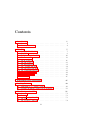
Contents
1 Introduction
1.1 Preamble . . . . . . . . . . . . . . . . . . . . . . . . . . . . .
1.2 Directory Structure . . . . . . . . . . . . . . . . . . . . . . . .
2 The
2.1
2.2
2.3
2.4
2.5
2.6
2.7
2.8
2.9
2.10
2.11
2.12
2.13
Ship
Bodies and Sub-bodies . .
Ship Files . . . . . . . . .
The Main Particulars File
The Frames File . . . . .
The Body Files . . . . . .
The SBody Files . . . . .
The ltwt.xml File . . . . .
The openings.xml File . .
The allowables.xml File .
The draftmarks.xml File .
The secmod.xml File . . .
The reg25.xml File . . . .
Tank Tables . . . . . . . .
.
.
.
.
.
.
.
.
.
.
.
.
.
.
.
.
.
.
.
.
.
.
.
.
.
.
.
.
.
.
.
.
.
.
.
.
.
.
.
.
.
.
.
.
.
.
.
.
.
.
.
.
.
.
.
.
.
.
.
.
.
.
.
.
.
.
.
.
.
.
.
.
.
.
.
.
.
.
.
.
.
.
.
.
.
.
.
.
.
.
.
.
.
.
.
.
.
.
.
.
.
.
.
.
.
.
.
.
.
.
.
.
.
.
.
.
.
.
.
.
.
.
.
.
.
.
.
.
.
.
.
.
.
.
.
.
.
.
.
.
.
.
.
.
.
.
.
.
.
.
.
.
.
.
.
.
.
.
.
.
.
.
.
.
.
.
.
.
.
.
.
.
.
.
.
.
.
.
.
.
.
.
.
.
.
.
.
.
.
.
.
.
.
.
.
.
.
.
.
.
.
.
.
.
.
.
.
.
.
.
.
.
.
.
.
.
.
.
.
.
.
.
.
.
.
.
.
.
.
.
.
.
.
.
.
.
.
.
.
.
.
.
.
.
.
.
.
.
.
.
.
.
.
.
.
.
.
.
.
.
3 Automating Data Conversion
1
1
4
7
7
8
10
13
16
23
31
34
37
39
41
42
45
47
4 Loading Patterns
49
4.1 Using Mate to bootstrap loadfiles . . . . . . . . . . . . . . . . 49
4.2 Creating an iniitial loading pattern manually. . . . . . . . . . 50
5 The
5.1
5.2
5.3
5.4
Configuration Files
Overview . . . . . . . .
Varient . . . . . . . . . .
The ctx mate.policy file
The ctx mate.config file
.
.
.
.
.
.
.
.
.
.
.
.
iii
.
.
.
.
.
.
.
.
.
.
.
.
.
.
.
.
.
.
.
.
.
.
.
.
.
.
.
.
.
.
.
.
.
.
.
.
.
.
.
.
.
.
.
.
.
.
.
.
.
.
.
.
.
.
.
.
.
.
.
.
.
.
.
.
.
.
.
.
.
.
.
.
51
51
52
53
54
iv
CONTENTS
5.5
The ctx mate fleets.tcl . . . . . . . . . . . . . . . . . . . . . .
55
6 Debugging and Introspection
57
6.1 Purpose . . . . . . . . . . . . . . . . . . . . . . . . . . . . . . 57
6.2 The ctx mate.debug file . . . . . . . . . . . . . . . . . . . . . 58
6.3 The Other debug files . . . . . . . . . . . . . . . . . . . . . . 59
Chapter 1
Introduction
1.1
Preamble
This document contains the instructions for preparing and testing the input
data files that CTX Mate (Mate) requires in order to be able to perform its
computations for a particular ship. This document assumes that the reader
is familiar with Mate as an user and intimately familiar with the CTX Mate
User Manual for this version. Almost nothing that is in the User Manual is
repeated in this document.
All the data files are in a simple XML format. Thus, they can be produced and changed by any editor. This manual assumes a basic familiarity
with the rules of XML and good working fluency in a general purpose text
editor. However, you can use a specialized XML editor if you wish.
Finally this manual assumes some knowledge of the basic Unix shell
commands. In order to modify the helper scripts for translating a current
ship data base to CTX Mate format, you will need to know a little Perl.
This is not necessary unless you want to save a lot of work
CTX Mate takes its input from three sources:
1. A directory containing a description of the ship.
2. A file containing the loading pattern, description of any damage, parcel
data, and the user options, etc in effect when the loading pattern was
created. This is called the loadfile.
3. Configuration files specifying the site’s CTX Mate data policy and
debugging/introspection options.
Chapter 2 describes the ship data files. Preparing these files is the big
job; everything else is almost trivial.
Often, all or almost all the ship data is already available in computerized
1
2
CHAPTER 1. INTRODUCTION
form. In this case, by far the easiest and most error-free way of creating
the CTX ship data files is to write script(s) which translate the data from
whatever format the yard/owner has been using to CTX format. Chapter
3 describes this process and the Perl scripts that have been provided for
this purpose. Generally these scripts will have to be modified to reflect
the details of your yard/owner data format. But usually the modifications
required are fairly straightforward. However, you will need to know a little
Perl to do these changes.
Chapter 4 talks about the loading pattern files. Normally, loading pattern files are produced by Mate itself; but, when a ship is first switched to
Mate, it is necessary to create an initial loading pattern outside Mate. A
template and a script for doing this is provided. And it is always possible
(although often not advisable) to produce or change a loading pattern file
manually.
Mate is designed to be used in applications ranging from preliminary
tanker design to on-board Loading Instrument. This requires both that the
program be highly configurable and that the level of flexibility be tightly
controlled. When Mate is being used in preliminary design a very lenient
ship data policy is both required and appropriate. When Mate is being
uses as an onboard Loading Instrument, an extremely tight data policy is
required.
Chapter 5 describes the Mate configuration files. These files are not
user preferences or options. User options are set by the user either on the
command line or from within the application. The Mate configuration files
represent site data policy. There are three such files:
ctx Varient.h This sets compile time options. In an onboard Loading Instrument application, these options requires Class Approval and cannot be changed.
ctx mate.policy This XML file allows the System Administrator to control site ship data policy; but only if the values in ctx Varient.h allow
this control. Normally in an onboard Loading Instrument application
they won’t.
ctx mate.config This XML file allows the System Administrator to control
site specific variables which do not require Class approval, even when
Mate is used as an on-board Loading Instrument, such as paper size,
printer commands, etc.
The configuration files should be writable only by System Adminstrators
and the like.
1.1. PREAMBLE
3
CTX Mate has a powerful debugging and introspection facility, which can
be used without recompilation. This capability is controlled by a number
of configuration files which are described in Chapter 6. It can be used not
just for debugging but also for observing exactly how Mate goes about its
calculations, allowing experts who are not computer programmers to see for
themselves what’s really going on.
This manual uses the following convention in referring to file names and
strings in general. Parts of a name that are fixed are shown in upright typewriter font. For example, the ship’s main particulars are always contained in
the main.xml file. Parts of a name that are variable are shown in constant
width italic. For example, a compartment whose name is xxxxxx must have
a body file body.xxxxxx. xxxxxx might be 1C or 2P B or ENG RM depending
on what compartment we are talking about.
This manual assumes that you are going to arrange your files according
to the CTX Tanker Filing System (TFS) as described in the next section.
CTX Mate itself does not require this arrangement. If you decide not to use
the TFS system, nothing much will change; but you will have to translate
the various directory names in this manual to your system.
4
1.2
CHAPTER 1. INTRODUCTION
Directory Structure
CTX Mate makes some assumptions about file directory (folder) structure.1
The basic concept is that the file system is broken down by fleet and within
each fleet by ship. Each ship has a fleet code which is the name of that ship’s
fleet folder. Each ship has a ship code which is the name of that ship’s ship
folder. For example, if the good ship Titanic is part of the A fleet and has a
ship code of ti, then the Titanic’s ship folder is TFS ROOT /A/ti.
TFS ROOT, the top of the tanker filing system, is specified by your
System Adminstrator. See Chapter 5. Unless changed at compile time,
TFS ROOT will default to /tfs which is its standard location in the CTX
Tanker Filing System. Check with your System Administrator to find out
what your TFS ROOT is.
By default, CTX Mate will use the fleet code and ship code specified at
compile time, which may be over-ridden by the values in the configuration
file if the compile time options allow, which will be further over-ridden by
the shell variables FLEET and SHIP if they exist, which will be further
over-ridden by the values supplied by the user at start up if they exist.
The ship code needs to be unique only within a particular fleet.2 In the
preliminary design context, fleet often corresponds to a design project, and
ship corresponds to a design alternative.
CTX Mate expects to find the data it needs for a particular ship in the
directory TFS ROOT /fleet/ship/DATA/Mate. where fleet is the fleet code
and ship is the ship code.
The user must specify a load file (loading pattern file) on start-up.
By default, CTX Mate looks into the current working directory for that
file. If the file is not there and the shell variable VOY NUM exists, it
looks in TFS ROOT /fleet/ship/V/nnn/CARGO. where nnn is the value of
VOY NUM. If VOY NUM does not exist or the file is not there, it looks
in TFS ROOT /fleet/ship/V/TEST. If the loading pattern file is not there,
Mate issues an error message and in interactive sessions asks the user for
1
This manual uses directory and folder as synonyms. Mate does not actually require
you to use the directory structure described in this section. See User’s Manual, Section 2.4.
But you will make life a lot easier both for your users and yourself, if you use something
like this very common system.
2
CTX recommends keeping fleet codes and ship codes very short. This saves lots of
typing and keeps path names that show up in report footers, etc within reasonable length.
Normally, fleet codes should be a single character, and ship codes two to four characters
(two for trading ships). Users gripe initially; but they quickly get used to this short-hand.
In any event the number of characters for these two codes is limited by the compile time
settings CTX MAX FLEET CODE and CTX MAX SHIP CODE respectively.
1.2. DIRECTORY STRUCTURE
5
another file name.
All this is consistent with the CTX filing system, described in the manual
CTX Tanker File System. CTX recommends you follow this system; but all
you really need to do is break your folders down by fleet and ship and put
the ship data in the DATA/MATE sub-directory of the ship’s folder.
The CTX Mate package includes the data files for a number of DEMO
ships. Hopefully, your System Adminstrator has put these files somewhere
where you have access to them. Often that somewhere is in TFS ROOT /X.
Talk to your Sysadmim to find out where these files are. They can be used
as templates for your own data files. And in many cases, it’s instructive to
inspect a complete set of working data files. In this Manual, often we can
only show you excerpts.
6
CHAPTER 1. INTRODUCTION
Chapter 2
The Ship
2.1
Bodies and Sub-bodies
Before we proceed, we need a little background on how CTX Mate models
a ship. A CTX Mate tanker is made up of Bodies. A Body is any normally
watertight volume. A Body may be a Hull, that is, a volume that displaces
water, or a Compartment, that is, a volume that contains liquid. A CTX
tanker can be made up of multiple Hulls and the entire watertight portion
of the ship must be divided into Compartments. Many (but not all) of the
ship’s Compartments are, of course, tanks.
Each Body (Hull or Compartment) is made up of Sub-bodies. Sub-bodies
come in three flavors: longitudinally oriented, transversely oriented, and ver- Only L-bodies are impletically oriented. Sub-bodies can be combined into a Body by both compo- mented in this version.
sition (addition) and deletion (subtraction).1 For example, a forepeak tank
might be modelled as the tank envelope (a longitudinally oriented sub-body)
less the chain lockers (vertically oriented sub-bodies) less the thruster duct
(a transversely oriented sub-body). A sub-body can be part of more than
one body. For example, the rudder trunk(s) might be deducted from both
the hull envelope, and the aft peak tank envelope.
In the CTX ship data files, each body file will merely reference the Subbody data file(s) of those sub-bodies that make up that body. The actual
offsets are in the sub-body files.
1
Mate’s addition and subtraction of sub-bodies is not Boolean union/difference. Only
non-intersecting sub-bodies may be added lest the intersection be counted twice. And
only a sub-body that is entirely within a body can be subtracted.
7
8
CHAPTER 2. THE SHIP
2.2
Ship Files
All the files describing a ship which Mate needs must be in the ship’s
TFS ROOT /fleet/ship/DATA/MATE directory.2 Your first job is to create
this directory if it does not already exist. This directory will contain the
following files.
main.xml This file contain the main ship particulars: LBP, beam, ship
name, etc. main.xml is described in Section 2.3.
frames.xml This file contains a list of all the ship’s frames including location, margin line at each frame, etc. frames.xml is described in
Section 2.4.
body.xxxxx For each of the ship’s hulls and each of the ship’s compartments, there must be a body.xxxxx file where xxxxx is the hull or
compartment name. Each such file references the sub-body file(s) for
the sub-bodies that make up that body. These files also contain overall
body data and, for bodies that are compartments, a description of the
compartment’s dipping points/gauging systems. See Section 2.5.
sbody.yyyyy For each sub-body yyyyy referenced by a body file, there
must be an sbody.yyyyy file which contains the orientation, offsets,
etc of that sub-body. This file also contains a description of the subbody’s permeability. See Section 2.6.
ltwt.xml This file contains the ship’s lightweight distribution. It is described in Sction 2.7.
constant wt.xml Sometimes yards distinguish between lightweight (pieces
of steel) and constant weights (for example, liquids in machinery)
which are really part of the lightweight. In this case, there will be a
constant wt.xml file. The format of this file is the same as ltwt.xml
and is described in Section 2.7.
openings.xml This file describes the location and type of all the downflooding points. See Section 2.8.
allowables.xml If the ship has been assigned shear force and bending moment allowables, there must be an allowables.xml file which contains
these allowables. See Section 2.9.
2
The one exception to this rule is the detailed scantling data. See Section 2.11 below.
Also in some cases described below, it may make sense to put a link to a ship data file in
this directory rather than the file itself.
2.2. SHIP FILES
9
secmod.xml This file describes the steel structure at each frame in beam
theory terms (moment of inertias, section moduli, etc.) It may also
reference detailed scantling data which is used in determining damaged
section strength parameters. secmod.xml itself is described in Section
2.11. The scantling data format is described in Appendix ??. This
scantling data, which can be quite copious, is contained in its own
directory.
imoreg25.xml This file contains the IMO Reg 25 (and Reg 16) hypothethical damage scenarios. See Section 2.12
Depending on the site’s CTX Mate data policy, some of these files may
not be required. For example, at the preliminary design stage, the ship’s
allowables have not yet been determined. However, when Mate is being
used on-board as a Loading Instrument, all these files will be needed. When
Mate is being used as a Loading Instrument, once the ship data has been
prepared, tested and, Class approved, the ship’s Mate data directory must
be made read-only.
10
2.3
CHAPTER 2. THE SHIP
The Main Particulars File
Here is a typical main.xml
<ctx_Main xmlns="http://www/c4tx.org/">
<fleetcode>
U
</fleetcode>
<shipcode>
al
</shipcode>
<lbp>
366.000
</lbp>
<mid_xs>
183.000
</mid_xs>
<beam>
68.000
</beam>
<depth>
34.000
</depth>
<shipname>
Hellespont Alhambra </shipname>
<imo_number> 9224752
</imo_number>
<sdwt>
441893
</sdwt>
<wdwt>
430184
</wdwt>
<tdwt>
453656
</tdwt>
<nprops>
1
</nprops>
<prop_xs>
6.953
</prop_xs>
<prop_ys>
0.000
</prop_ys>
<prop_zs>
6.500
</prop_zs>
<prop_diam>
10.500
</prop_diam>
<conn_xs> 51.500
</conn_xs>
<conn_ys> 0.000
</conn_ys>
<conn_zs> 58.200
</conn_zs>
<prow_xs> 373.500
</prow_xs>
<prow_ys> 0.000
</prow_ys>
<prow_zs> 36.600
</prow_zs>
<mani_xs> 187.000
</mani_xs>
<mani_ys> 29.400
</mani_ys>
<mani_zs> 35.550
</mani_zs>
<pmb_fwd_xs> 256.174
</pmb_fwd_xs>
<pmb_aft_xs> 164.719
</pmb_aft_xs>
<trim_max> 10.000
</trim_max>
<trim_min> -10.000
</trim_min>
<draft_warn> 7.700
</draft_warn>
<saab_yn> YES
</saab_yn>
<blst_ig_yn> Y
</blst_ig_yn>
<classcode>
LR
</classcode>
</ctx_Main>
2.3. THE MAIN PARTICULARS FILE
11
The format is obvious. The outer element is ctx Main. The inner XML
element tag is the variable name. This name must be followed exactly.
The element text with leading and trailing white space removed is the value.
Otherwise you are free to move the data around any way you want to, as
long as it is legal XML. In particular, the variables can be in any order.
Numbers must follow American practice, using ”dot” for the decimal
point. Any commas in a number will be extracted and thrown away. This
is true of all numbers anywhere in the CTX Mate input. Mate does range
checks on numbers. If a number is outside the legal range, you will get
an error message. The extreme legal values can be found in the source file
ctx Varient.h.
If the site policy variable allow missing data is N, then main.xml must
have all these variables. Otherwise only, the first six are required.3 In the
preliminary design context, the other variables may be either unavailable,
output of the design process, or simply unnecessary. In the Loading Instrument context, all these variables are legally important and must be supplied.
Most of the variable names are self-explanatory but a few require comment. Any variable ending in xs is distance foward of the AP in meters.
Any variable ending in ys is distance port of centerline in meters. Any
variable ending in zs is distance above baseline. For CTX Mate, port ys
is positive and starboard is negative.
The first three variables starting with prop specify the center of the
propeller for propeller immersion calculations. if the ship is twin screw
set nprops to 2 and prop ys must be the transverse location of the port
propeller.
The three variables starting with conn specify the helm location and the
three variables starting with prow specify the top of the bulwarks centerline
all the way forward for blind spot calculations.
The three variables starting with mani specify the the center of the presentation flanges of the port manifold. This is used in air draft calculations.
Mate assumes the manifolds are symmetric.
The two variables starting with pmb are the forwardmost and aft most
extent of the parallel midbody. Mate follows the JTP system. Trim by the
bow is positive; trim by the stern is negative. If trim by the bow exceeds
trim max ot trim by the stern is less than trim min, Mate will issue a
warning. If draft at the FP is less that draft warn, then Mate will issue
a warning. All these warnings can be turned off by making these numbers
large enough.
3
However, Mate will use whatever variables are supplied, even if they are not required.
12
CHAPTER 2. THE SHIP
The main.xml file may contain any other particulars you desire. Mate
will just ignore them. In fact, it is excellent practice to have a single ship
particulars file that has all the ship’s “permanent particulars”, for example
all the permanent stuff that the OCIMF questionnaire requires. In the CTX
system, this file is TFS ROOT /fleet/ship/DATA/PERM/main.xml and is used
by any application that needs this data of which Mate is only one of many.
To implement this, put a link to this main particulars file in DATA/PERM in
the TFS ROOT /fleet/ship/DATA/MATE rather than the file itself. That way,
whenever one of the “permanent” particulars changes — as it eventually will
— you will only have to make one change. If your system does not support
links, the same effect can be obtained by putting an external entity reference
in the file in the DATA/MATE directory.
The main.xml file is so small and so idiosyncratic that no tools have
been developed for automating the process of creating this file. Your best
bet is to copy the existing main.xml from one of the demo ships in the
source DEMO directory to your ship’s TFS ROOT /fleet/ship/DATA/MATE
directory and then change the element contents to match your ship. That
way you won’t misspell the variable names. No ampersands or less than
signs in the text strings.
13
2.4. THE FRAMES FILE
2.4
The Frames File
Here is a portion of a typical frame.xml
<ctx_Frames fleet="U" ship="al" author="djw1" timestamp="2005-12-22T12:35:32Z">
<ctx_Frame name="TRNSM
" xs=" -6.500" ys=" 10.000" zs=" 31.489" show="Y"
tbhd="TRANSOM"/>
<ctx_Frame name="FRm07
" xs=" -5.950" ys=" 10.296" zs=" 31.474" show=" "/>
<ctx_Frame name="FRm06
" xs=" -5.100" ys=" 10.752" zs=" 31.445" show=" "/>
<ctx_Frame name="FRm05
" xs=" -4.250" ys=" 11.208" zs=" 31.426" show=" "/>
<ctx_Frame name="FRm04
" xs=" -3.400" ys=" 11.663" zs=" 31.403" show=" "/>
<ctx_Frame name="FRm03
" xs=" -2.550" ys=" 12.116" zs=" 31.379" show=" "/>
<ctx_Frame name="FRm02
" xs=" -1.700" ys=" 12.565" zs=" 31.356" show=" "/>
<ctx_Frame name="FRm01
" xs=" -0.850" ys=" 13.009" zs=" 31.332" show=" "/>
<ctx_Frame name="FRm01f " xs=" -0.849" ys=" 13.009" zs=" 31.332" show=" "/>
<ctx_Frame name="AP
" xs="
0.000" ys=" 13.450" zs=" 31.310" show="Y"/>
.....
lots more frames ....
<ctx_Frame name="FR126
<ctx_Frame name="FR127
<ctx_Frame name="FR128
<ctx_Frame name="FR129a
<ctx_Frame name="FR129
tbhd="FPVOID "/>
<ctx_Frame name="FR130
<ctx_Frame name="FR131
<ctx_Frame name="FR132
<ctx_Frame name="FR133
<ctx_Frame name="FR134
<ctx_Frame name="FR135
<ctx_Frame name="FR136
<ctx_Frame name="FR137
<ctx_Frame name="FR138
<ctx_Frame name="FR139
<ctx_Frame name="FR140
<ctx_Frame name="FR141
<ctx_Frame name="FR142m
<ctx_Frame name="FR142
</ctx_Frames>
"
"
"
"
"
xs="
xs="
xs="
xs="
xs="
360.500"
361.350"
362.200"
363.049"
363.050"
ys="
ys="
ys="
ys="
ys="
15.678"
15.015"
14.327"
13.609"
13.609"
zs="
zs="
zs="
zs="
zs="
34.954"
34.988"
35.024"
35.061"
35.061"
show=" "/>
show=" "/>
show=" "/>
show=" "/>
show="Y"
"
"
"
"
"
"
"
"
"
"
"
"
"
"
xs="
xs="
xs="
xs="
xs="
xs="
xs="
xs="
xs="
xs="
xs="
xs="
xs="
xs="
363.900"
364.750"
365.600"
366.540"
367.300"
368.150"
369.000"
369.850"
370.700"
371.550"
372.400"
373.250"
373.400"
373.500"
ys="
ys="
ys="
ys="
ys="
ys="
ys="
ys="
ys="
ys="
ys="
ys="
ys="
ys="
12.861"
12.081"
11.267"
10.418"
9.528"
8.592"
7.595"
6.487"
5.232"
3.770"
1.785"
0.627"
0.600"
0.000"
zs="
zs="
zs="
zs="
zs="
zs="
zs="
zs="
zs="
zs="
zs="
zs="
zs="
zs="
35.100"
35.141"
35.183"
35.227"
35.274"
35.322"
35.374"
35.400"
35.400"
35.400"
35.400"
16.000"
13.000"
14.000"
show="
show="
show="
show="
show="
show="
show="
show="
show="
show="
show="
show="
show="
show="
Again the format is almost self-explantory. The outer element is a
ctx Frames. It has four attributes: the ship’s fleet code, the ship’s ship
code, the author of this file, and the GMT time the file was last modified.
All timestamps in CTX Mate must follow the ISO 8601 format exactly.
Each inner XML elements is a ctx Frame which not surprisingly represents a frame. Each ctx Frame element has six attributes.
"/>
"/>
"/>
"/>
"/>
"/>
"/>
"/>
"/>
"/>
"/>
"/>
"/>
"/>
14
CHAPTER 2. THE SHIP
name A name for the frame which must be unique within the frame file.
The name can be up to CTX MAX FRAME NAME characters long.
It cannot contain any ampersands, less than signs, or embedded blanks.
Leading and trailing white space is stripped, All blanks is not a valid
frame name. This attribute is always required.
xs The longitudinal position of the frame forward of the Aft Perpendicular
(AP). The frames must occur in order of increasing xs, that is the
aftmost frame at the top, and the forward most frame as the bottom.
This attribute is always required. There must be a frame named AP
with an xs of 0.000. There must be a frame named FP with an xs of
LBP.
ys The transverse position of the margin line at this frame. CTX MATE
assumes the margin line is symmetric. This attribute is always required.
zs The vertical position of the margin line at this frame above the base line.
This attribute is always required.
show If this single character flag is Y, this frame will be highlighted on the
bending moment and shear force diagrams, and show up in the short
form of the longitudinal strength report. Otherwise, the frame will
only show up in the long form of the strength report. Generally, show
should be Y for the FP, AP, all frames which are on major bulkheads,
and any frames required by Class (usually the frames at which the allowables are explicitly assigned), If this attribute is missing, it defaults
to a single blank.
tbhd If the frame is on a bulkhead, then this attribute should be the name
of that bulkhead. This attribute is not required by CTX Mate.
Frames are not as central to a ship description in the CTX system as
they are in most schemes. The various sub-bodies that make up the ship
each have there own orientation and their own set of sections. There is no
requirement that any sub-body sections be on a frame. The main use that
Mate makes of frames is in depicting the results of the longitudinal strength
calculations, and comparing those results with the Class allowables.
However, unless you have lots of frames – at least one frame for every
actual web frame and unless the sections for the major longitudinal subbodies are also on these frames – then Mate will generate artificial bumps
in the shear force curve. If these bumps happen to occur at the shear force
2.4. THE FRAMES FILE
15
max/min, then Mate could declare a loading pattern illegal when in fact it
is not. For the same reason, you will need a frame on either side of each
major tank bulkhead. . Finally in situations where single barrel accuracy is Why not have Mate do this
required for OBQ calculations with trim by the stern, and the tank frame based on tbhd
spacing is 3 meters or more, it is a good idea to put a tank section at half
the the web frame spacing forward of the aft bulkhead of the tank.4 In this
case, there should be a frame in frames.xml at this longitudinal position
as well. Finally, it is usually a Class requirement that there be a frame at
every longitudinal position for which Class explicitly assigns an allowable.
Normally, these positions will be on the bulkheads, but this in not always
the case.
By now, the value of the legibility of the XML format should be clear.
But preparing big XML files manually is a horrific nuisance. Compared with
a simple table, they involve an enormous number of extra key strokes. And
one has to carefully keep track of all the greater than signs, the less than
signs, and myriad quotes.
CTX has developed a far easier way based on simple offset tables. This
is described in Chapter X. If you follow this system, prepare the necessary offset tables, then the corresponding frame.xml file can be generated
automatically by using the frames2xml.pl command.5 This system also
guarantees a great deal of internal consistency. See Chapter X for the details. But I suggest you read the rest of this chapter first, because the same
system is used to generate many of the other files described in this chapter.
4
For the reasoning behind these strange requirements, see the programmer’s manual,
sections xx and yy.
5
If the ship’s data is already computerized in some form of offset tables, it is usually
a fairly simple job to write a script for converting these offsets tables to the Chapter X
tables, from which the XML files can be generated automatically.
16
2.5
CHAPTER 2. THE SHIP
The Body Files
Each Body that makes up the ship must have a body.xxxxx file in the ship’s
MATE data folder, TFS ROOT /fleet/ship/DATA/MATE, where xxxxx is the
Body’s name. Here is a a typical Body file.
<ctx_Body name="1P" type="C" fleet="U" ship="al" seg="3"
volbook="22301.0" max_ullage_head="1.400" min_ullage_head="-0.400"
gen_by="tank2xml.pl" at="2006-05-28T17:01:14Z" author="" ref="">
<ctx_SBody name="1P_main" add_or_sub="A"/>
<ctx_Dip_Point code="UL" type="E" note="">
<ctx_PointS xs=" 301.190" ys=" 16.235" zs=" 35.6860"/>
<ctx_PointS xs=" 301.190" ys=" 16.235" zs=" 3.3000"/>
</ctx_Dip_Point>
<ctx_Dip_Point code="SA" type="S" note="">
<ctx_PointS xs=" 301.190" ys=" 17.235" zs=" 35.6860"/>
<ctx_PointS xs=" 301.190" ys=" 17.235" zs=" 3.3000"/>
</ctx_Dip_Point>
<ctx_Dip_Point code="DA" type="E" note="">
<ctx_PointS xs=" 301.520" ys=" 22.975" zs=" 34.7000"/>
<ctx_PointS xs=" 301.520" ys=" 22.975" zs=" 3.3000"/>
</ctx_Dip_Point>
<ctx_Dip_Point code="DM" type="E" note="">
<ctx_PointS xs=" 326.400" ys=" 16.900" zs=" 35.0000"/>
<ctx_PointS xs=" 326.400" ys=" 16.900" zs=" 3.3000"/>
</ctx_Dip_Point>
<ctx_Dip_Point code="DF" type="E" note="">
<ctx_PointS xs=" 348.500" ys=" 8.200" zs=" 35.4000"/>
<ctx_PointS xs=" 348.500" ys=" 8.200" zs=" 3.3000"/>
</ctx_Dip_Point>
</ctx_Body>
Body files are surprisingly compact. The outer element is a ctx Body. This
element has nine possible attributes.
name The body’s name which must be unique within this ship and which
must match the second part of the file name. The body name can be
up to CTX MAX BODY NAME characters long. As always leading
and trailing white space is stripped. The body name can contain only
normal alphanumeric characters plus underscore. This attribute is
always required.
type type is a single character flag which must be one of
H This body is a hull. A ship may have as many as CTX MAX HULLS
hulls; but it is usually best to represent a tanker as a single hull
and use sub-bodies to represent rudder(s), propeller(s), etc. Any
body which is not type H is called a compartment.
2.5. THE BODY FILES
17
C Compartment is a standard cargo tank (not gale ballast, not slops).
G Compartment is a gale ballast tank, that is, a cargo tank into which
a master may legally put ballast if he determines this is required
for the ship’s safety.
S Compartment is a slop tank, that is, a cargo tank which is specially
fitted to facilitate the separation of oil and water.
B Compartment is a ballast tank.
f Compartment is a heavy fuel oil tank.
d Compartment is a diesel oil tank.
c Compartment is a cylinder lube oil oil tank.
s Compartment is a system lube oil tank.
w Compartment is a fresh water tank.
L Compartment is a tank, but liquid is not otherwise specified.
V Compartment is not a tank, normally dry.
The type attribute is always required.
fleet The ship’s fleet code.
ship The ship’s ship code.
seg This is a single character flag which indicates which segregation this
body belongs to. This attribute applies only to cargo tank compartments and is not required. If a cargo tank compartment is not given
a segregation, this variable defaults to a single blank.
volbook volbook is the “official” tank capacity at 100% full in cubic meters. It applies only to tanks. If the policy variable allow mis{CONsing data is N and the body type is neither H nor V, this attribute is required. If not and the attribute is missing, Mate will
compute its own tank capacity. Due to idiosyncracies in ship yard and
Class procedure and software, (OK, and CTX software), the official
tank capacity may be very slightly different from that computed by
Mate.
max ullage head This attribute is maximum pressure head in meters water gage. If the tank is vented, it should be set to zero. Otherwise it
should normally be set to the P/V valve pressure setting. However,
design programs might set this value to the tank’s structural limit.
18
CHAPTER 2. THE SHIP
If the policy variable allow missing data is N and the body type is
neither H nor V, this attribute is required. If not and the attribute is
missing, it will default to zero.
min ullage head This attribute is minimum pressure head in meters water
gage. This number must always be non-positive. If the tank is vented,
it should be set to zero. Otherwise it should normally be set to the
P/V valve’s vacuum setting. However, design programs studying vacuum based spill reduction systems might set this value to the tank’s
structural limit. to the tank’s structural limit. If allow missing data
is N and the body type is neither H nor V, this attribute is required.
If not and the attribute is missing, it will default to zero.
gen by This attribute can be used to indicate how this file was produced.
It is not required by Mate.
at This attribute can be used to indicate when this file was produced. It is
not required by Mate.
author This attribute can be used to indicate the person responsible for
producing this file. It is not required by Mate.
ref This attribute can be used to indicate the data source(s) on which this
file was based. It is not required by Mate.
A body file can have two kinds of inner elements. The most important
kind is the ctx SBody element. Each body files must contain one ctx SBody
for each of the sub-bodies than make up this body. A ctx SBody has just
two attributes, both required.
name The name of the sub-body which may be up to CTX MAX SBODY NAME characters long. Leading and trailing white space is stripped.
The name can consist of only alphanumeric characters and underscore,
and must be unique within the ship. And the name must match the
second portion of the corresponding SBody file.
add or subtract A single character flag which must be either A (add the
sub-body volume to the body volume) or S (deduct the sub-body volume from the body volume).
Obviously, each Body file must contain at least one ctx SBody element.
The other kind of inner element is a ctx Dip Point. In CTX parlance a
dipping point is any combination of gauging system and location. It might
2.5. THE BODY FILES
19
be standard dipping or sounding point or a float system or a radar gauge,
or some sort of pressure sensing system. The ctx Dip Point applies only to
compartments.
Each dipping point element has up to four attributes and one or more
ctx PointS sub-elements. The attributes are:
code A two-character code which identifies this dipping point. The code
need be unique only within this tank. By convention, the code naming
indicates the sort of dipping point: UL for ullage hatch, SA for Saab
radar, WH for whesso gauge, etc but this is only a convention. However,
this convention does serve as a useful mnemonic for the crew. The code
IM is reserved, see below. This attribute is always required.
type This is a single character flag which must be E, S, P, or H. E indicates the dipping point works in earth coordinates. Examples are a
surveyor’s tape and UTI gauges which fall in the direction of gravity,
regardless of the ship’s trim or heel. S indicates the dipping point
works in ship coordinates. Examples are Whesso gauges and radars
which are fixed to the ship. P indicates a path in ship coordinates,
such as a sounding pipe. Mate models sounding pipes as a series of
straight lines. H indicates a pressure sensing system. H systems are
similar to E systems in that they work in earth coordinates; but, in
the case of H systems, the fixed point is very low in the tank, while in
E system the fixed point is at the top of the tank. This attribute is
always required.
Mate keeps track of the coordinate system within which a gauging system works. Many Loading Instruments (and some shipyard tank table
software) do not. This failure generates commercially significant errors, even at very modest trim and heel, and totally incorrect numbers
at high trim and heel.
offset This attribute applies to and is required only by H type systems.
Pressure sensing system have a minimum innage below which they will
fail to register even at zero trim and heel, either because the sensor is
not exactly at the tank’s lowest point or there is a deadband in the
sensor itself. This innage is called the offset. Note Mate expects the
offset like all measurements to be in meters. Vendors generally supply
the offset in centimeters.
note You may use this attribute to indicate the data source(s) for the dipping point particulars. It is not required by Mate.
20
CHAPTER 2. THE SHIP
Each ctx Dip Point contains one or more ctx PointS sub-elements. A
ctx PointS is a point in ship space. The three attributes are the longitudinal, transverse, and vertical positions. H systems must have exactly one
such point, which is the location of the sensor. E and S systems must have
exactly two such points. For E, S, and P, dipping points, the first point is
the reference point at the top of the tank. For E and S dipping point, the
second and last point is the bottom of the tank directly below the reference
point. P dipping points are modelled as a series of straight lines. For each
such line segment as we move down the tank, the point is the bottom of
the line segment. If the sounding pipe is modeled as four line segments,
then the corresponding ctx Dip Point will have a total of five ctx PointS
sub-elements.
For an operational tanker, you should have a dipping point for every location the crew might use. If a tank is equipped with an ullage hatch, a Saab
radar, and three UTI valves, then that tank should have five ctx Dip Point
elements in its body file. This is the case for the sample file on page 16.
The UTI valves have been named DA (dip aft), DM (dip mid), and DF (dip
fwd). MATE is designed so that the Chief Officer should never have to pick
up a calculator in order to “correct” one dipping point’s measurements to
another.
Whether a body file must have any dipping point, depends on the body
type, and the setting of the site policy variable need dipping point. If the
body is a hull, no ctx Dip Point element is required and any supplied will
be ignored.
• If need dipping point is N, then there need be no dipping point in
any compartment Body file; and, if there is none, Mate will concoct a
single dipping point with the code IM for the compartment.6 This is
appropriate in preliminary design applications where the dipping point
locations are not yet fixed. At this point, the designer should never
use the U or I tank opts, and a dipping point really isn’t required.
However, it simplifies the software a great deal, to be able to assume
that every compartment has at least one dipping point.
• If need dipping point is V, then Mate will require at least one dipping point for each non-V type compartment. This is appropriate for
situations where the ship yard has given each tank at least one dipping point, but not the (normally) dry compartments. The problem is
6
The IM (Imaginary) dipping point is an E type dipping point whose location is in
the middle of the tank in plan view and whose reference height is the highest point of the
tank in ship coordinates.
2.5. THE BODY FILES
21
that, if the dry compartment is damaged, while Mate’s volumetric and
weight calculations will be correct, the compartment’s ullage/innage
will be at best approximate. Worse, the crew probably has no way of
measuring the ullage or innage in the damaged compartment.
• If need dipping point is Y, then Mate will require at least one dipping point for each compartment. This is appropriate for situations in
which the owner has required all compartments be given some sort of
sounding capability in his newbuilding spec, which is something that
all good owners should do.
As we have seen, the body files are quite small. A hull body file will be
only three or four lines long. The explanation is far, far more verbose than
the file itself. If you use the system outlined in the next chapter, templates
for each of the ship’s body files will be created; but you will have to put in
the dipping point data yourself.
It should be clear by now there is a great deal of structure to the XML
ship data files. This structure closely mimics Mate’s internal view of the
ship. For the programmers among you, just about every XML element
matches one of the classes that together make up the ship. In fact, in most
cases the name of the class and the name of the element are the same.
In the CTX Mate input, there is no list of the ship’s compartments.
Mate makes up that list from the body.xxxxxx files in the Mate ship folder.
This makes it easy to add or delete a compartment. Conversely, it allows
you to screw up. Mate does not check that there is a compartment for every
point within the ship. A common practice is to start out by doing only the
tanks, running Mate as required to get them right, and only then doing the
dry compartments. The dry compartments are not needed for any of the
normal Loading Instrument stuff; but, if you leave out a dry compartment,
Mate’s ability to simulate damage will be compromised. For example, if you
leave out the compartment enclosed by a rudder, you won’t be able to flood
that rudder.
Conversely, Mate does not check that the compartments don’t overlap.
You can put two compartments in the same space and Mate will fail to complain. If you want to “comment out” a compartment, that is, delete it but
keep the data available, you must change the name of that compartment’s
file making sure the new name does not start with body. I usually change
body.name to cody.name to avoid conflicts with meaningful prefixes.
Finally, Mate does only the most rudimentary checks that a compartment is inside a hull. Mate will accept compartments that extend outside the
ship. Basically, it is your responsibility to ensure that every point within the
watertight boundaries of the ship is within one and only one compartment.
22
CHAPTER 2. THE SHIP
However, if you use the system described in the next chapter, fullfilling this
responsibility becomes much easier.
2.6. THE SBODY FILES
2.6
23
The SBody Files
The sub-Body files are where all the action and all the work is. Each subbody that is part of any of the ship’s bodies must have a sbody.yyyyyyyy
file in the ship’s Mate data folder, where yyyyyyyy is the sub-body’s name.
Sub-bodies comes in three flavors:
LBodies LBodies are longitudinally oriented sub-bodies which are described TBodies and VBodies are
by a series of transverse sections (constant xs curves). This is the not implemented in this verstandard (and usually the best way) of representing the hull and com- sion.
partment envelopes.
TBodies LBodies are transversely oriented sub-bodies which are described
by a series of buttocks (constant ys curves). This is usually the best
way of representing thruster ducts and tranversely oriented piping and
ducts.
VBodies VBodies are vertically oriented sub-bodies which are described by
a series of waterlines (constant zs curves). This is usually the best way
of representing rudders, chain lockers, and vertically oriented piping.
Sometimes we need to refer to section/buttock/waterline collectively, in
which case the manual uses the word slice. LBodies are a bunch of transverse
slices, TBodies a bunch of longitudinal slices, VBodies a bunch of horizontal
slices.
24
CHAPTER 2. THE SHIP
2.6.1
LBodies
We begin with LBodies. Here is the top and bottom of a typical sbody file
for an LBody
<ctx_SBody name="SG_ROOM_main" kind="L" fleet="U" ship="al"
gen_by="tank2xml.pl" at="2006-05-28 17:01:13" author="" note="">
<ctx_Curve type="X" name="" plane="-6.500" reflect="N" mold="I" note="">
<ctx_Offset ys=" 0.000" zs="25.600" nuck=" " cut=" " note=""/>
<ctx_Offset ys=" 8.761" zs="25.600" nuck=" " cut=" " note=""/>
<ctx_Offset ys=" 9.300" zs="26.000" nuck=" " cut=" " note=""/>
<ctx_Offset ys=" 9.682" zs="27.000" nuck=" " cut=" " note=""/>
<ctx_Offset ys=" 9.921" zs="28.000" nuck=" " cut=" " note=""/>
<ctx_Offset ys=" 10.000" zs="29.000" nuck=" " cut=" " note=""/>
<ctx_Offset ys=" 10.000" zs="31.489" nuck=" " cut=" " note=""/>
<ctx_Offset ys=" -0.000" zs="32.454" nuck=" " cut=" " note=""/>
<ctx_Offset ys="-10.000" zs="31.489" nuck=" " cut=" " note=""/>
<ctx_Offset ys="-10.000" zs="29.000" nuck=" " cut=" " note=""/>
<ctx_Offset ys=" -9.921" zs="28.000" nuck=" " cut=" " note=""/>
<ctx_Offset ys=" -9.682" zs="27.000" nuck=" " cut=" " note=""/>
<ctx_Offset ys=" -9.300" zs="26.000" nuck=" " cut=" " note=""/>
<ctx_Offset ys=" -8.761" zs="25.600" nuck=" " cut=" " note=""/>
<ctx_Offset ys=" -0.000" zs="25.600" nuck=" " cut=" " note=""/>
</ctx_Curve>
..... lots more ctx_Curves .......
<ctx_Curve type="X" name="" plane="14.450" reflect="N" mold="I" note="">
<ctx_Offset ys=" 0.000" zs="25.600" nuck=" " cut=" " note=""/>
<ctx_Offset ys=" 7.000" zs="25.600" nuck=" " cut=" " note=""/>
<ctx_Offset ys=" 7.000" zs="31.640" nuck=" " cut=" " note=""/>
<ctx_Offset ys=" -0.000" zs="31.921" nuck=" " cut=" " note=""/>
<ctx_Offset ys=" -7.000" zs="31.640" nuck=" " cut=" " note=""/>
<ctx_Offset ys=" -7.000" zs="25.600" nuck=" " cut=" " note=""/>
<ctx_Offset ys=" -0.000" zs="25.600" nuck=" " cut=" " note=""/>
</ctx_Curve>
<ctx_Perm_Table ref="" note="">
<ctx_Perm zs=" 27.000" perm="0.96000" note=""/>
<ctx_Perm zs=" 50.000" perm="0.95000" note=""/>
</ctx_Perm_Table>
</ctx_SBody>
The outer element is a ctx SBody. It has as many as eight attributes.
name A name for the sub-body. The name may be up to CTX MAX SBODY NAME characters long and contain only alphanumeric characters and underscore. The sub-body name must be unique within this
ship and match the second part of the corresponding sbody file. This
attribute is always required.
2.6. THE SBODY FILES
25
kind A single character flag which must be L for longitudinally oriented subbodies, T for tranversely oriented, This attribute is always required.
fleet The ship’s fleet code. This attribute is always required.
Why required?
ship The ship’s ship code. This attribute is always required.
Why required?
gen by
at
author
ref
A ctx Sbody element must contain at least two ctx Curve elements followed by at most one ctx Perm Table element. The ctx Curve elements are
the heart of the matter. Each ctx Curve element has up to six attributes.
type The curve type is a single character flag which in general must be one
of X (constant xs curve), Y (constant ys curve), Z (constant zs curve),
or S (general 3-D space curve). For LBodies, type must always be X.
This attribute is always required.
name A name for the curve. This attribute is neither required nor used by
Mate.
plane The axial location of this slice. For X curves, this is the longitudinal position of the section forward of the Aft perpendicular. All the
ctx Curve elements must be in increasing plane order. For LBodies,
this means aftmost to fwdmost.
reflect This flag must be one of R, T or N. For LBodies, a reflect of
R implies that the sub-body is tranversely symmetric and only the
port half is given in this ctx Curve element. In this case the first
ys and the last ys in the offsets must be equal, and Mate will create
the starboard side by reflecting the port half about this ys. For hull
envelopes, reflect is almost always set to R, only the port half of the hull
is given, the first and last ys is zero, and the starboard side is created
by reflection about the ship centerline. A reflect of T implies that
the sub-body is vertically symmetric and only the top side looking in
the axial direction is given in this ctx Curve element. In this case,
the first and last zs in the offsets must be the same and the bottom
is created by reflecting the top around this horizontal plane. The T
26
CHAPTER 2. THE SHIP
option is rarely ever useful for ship LBodies; but, as we shall see, it
can be valuable for TBodies and VBodies. A reflect of N implies
that the entire curve is given in the offsets in which case the first point
on the curve and the last must be the same. This attribute is always
required. For LBbodies this is the port side.
mold This flag must be one of I, O, or blank. I implies the moldline in
on the inside of the curve, O (letter O) implies the moldline in on the
outside of the curve, blank means don’t know and don’t care. This
attribute is neither required nor used by this version of Mate.
note This can be any commentary on this curve such as data sources, etc.
This attribute is neither required nor used by this version of Mate.
Each ctx Curve element must contain at least two ctx Offset elements.
For X curves, the ctx Offset attributes are:
ys The transverse location of the offset. Once again this is distance from
the ship centerline in meters, port positive and stbd negative. This
attribute is always required.
zs The vertical location of the offset. Once again this is distance from the
ship baseline in meters, above baseline is positive, below is negative.
This attribute is always required.
nuck This is a knuckle flag. It must be one of blank, K, H, V ..... Blank
means no knuckle, fairing, drawing programs, etc should attempt to
put a smooth curve through the point. K says there is a knuckle at
this point. H tells fairing/drawing programs to force the slope to zero
at this point. V tells fairing/drawing programs to force the slope to
vertical at this point. Mate neither uses nor requires this attribute.
cut This flag indicates whether a point is inside a cut. See below for explanation. It may be either Y or N. It is not required and, if missing,
will default to N.
note Any commentary on the offset. Mate neither uses nor requires this
attribute.
The offsets must be given in clockwise order looking forward. Conventionally, the first offset is the lowest point on the curve, but this is not
required. If reflect is N, this must be a closed curve. The first (ys, zs) and
the last must be the same. If reflect is R, the first ys and the last must be
2.6. THE SBODY FILES
27
the same If reflect is T, the first zs and the last must be the same Notice
that for Mate the description of the hull must include at least the port half
of the deck. The offsets do not stop at the margin line.
The Kerwin immersed slice integration algorithm used by Mate is extremely flexible. The section curve is completely arbitrary as along as it
does cross over itself. However portions of the curve can touch each other.
This is known as a cut. Cuts can be used to remove interior portions of the
slice from a sub-body. Suppose you want to remove a pipe from a section.
This can be done by proceeding clockwise around the section to some point,
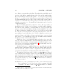
cutting straight into the pipe, proceeding counter-clockwise around the pipe Need sketch
back to the cut, and go back out to the section, along the same cut.7 In
order to ensure that wetted surface calculations are correct, you must mark
the points that are in the cut including the points at the end of the cut by
setting the cut flag to Y. Cuts can also be used to connect non-contiguous
portions of a section. Bulbous bows are a common example. At the forward end of a ship with a bulbous bow the transverse section is split into
two pieces: a lower portion consisting of the bulb and an upper portion in
way of the prow. No problem. Simply generate a X curve starting at the
bottom of the bulb centerline, move clockwise around the port side of bulb
to the top of the bulb centerline, then start a vertical cut up to the bottom
of the prow centerline, and move clockwise round the upper hull until you
reach the deck centerline. Then either set reflect to R (recommended) or
work your way down the starboard side. In either case, the starboard side
will be a mirror image of the port side, and the cut is a vertical line on the
centerline. The cut has no section area, so it will not affect the immersed
area calculations. And by marking the cut with the cut flag, Mate will not
include the cut in its wetted surface calculations.
Mate integrates section areas via the trapezoidal rule. This means that
you will need closely spaced offsets in way of highly curved regions of the
sub-body. If the curvature is small, you can get by with more widely spaced
offsets. In areas where the section curve is a straight line. you need only an
offset at either end of the straight region. There is no requirement that the
number of offsets on one ctx Curve is the same as another, The sample file
on page 24. The space being modelled is the steering gear compartment. The
aft end of this compartment goes out to the shell. So we use six waterlines
to represent this curve. However, at the forward end of this compartment,
the outboard side of the compartment is a tank bulkhead, so we need only
7
In the CTX system removal of interior portions is usually better done with a subtractive sub-body.
28
CHAPTER 2. THE SHIP
two offsets to represent this vertical line. For tankers the most highly curved
portions of the hull are usually the turn of the bilge and the gunnel radius.
If you represent these curves by five points — one every 22.5 degrees along
the arc — you will not only obtain far more accuracy than is required for
Loading Instrument purposes, but you will obtain all the accuracy that is
required for commercial cargo survey purposes. In other curved areas, a
waterline every meter or so is generally more than what is needed even for
commercial purposes.
However, it is important that you have lots of slices. For cargo tanks, you
should have a slice at least every web frame, even if the tank is prismatic.
If a tank is totally prismatic, you might think you could represent it with
just two sections, the aft bulkhead and the forward bulkhead. If you did
so, Mate’s hydrostatic calculations would be correct. However, if the tank
is of any size, you would generate a big bump in the shear force curve. To
prevent this, you need thin slices. A good rule of thumb is a section every
actual web-frame, and if the web frame spacing is large – say more than
three meters – a section half-way between the aft bulkhead in the tank and
the first web frame forward of this bulkhead.
Finally, in order to avoid artificial bumps in the shear force curve, the
sections of the the main hull sub-body, should match the tank sections. In
particular, this means that each major transverse bulkhead must be represented as two sections in the main hull LBody.8 Conventionally, these two
sections are spaced a millimeter apart.
All this sounds more complicated than it is, especially if you use the
system described in Chapter XXX. If you use the Chapte XXX approach,
then the main LBody files for all the compartmentes and the hull will be
generated automatically in a manner that abides with all these rules.
The final sub-element in a sub-body file is a ctx Perm Table. Mate allows a fairly flexible description of sub-body permeability. For permeability
purposes, the sub-body is divided into one or more horizontal layers in ship
space. Each layer is represented by a ctx Perm sub-element. The layer must
be given in bottom to top order, A ctx Perm element has two attributes,
both always required.
zs This is the top of the permeability layer. The bottom of the first (lowest)
layer is assumed to be the lowest point in the compartment in ship
coordinates. The first zs in the ctx Perm Table must be no smaller
8
This is required so the the hull slice buoyancy spikes match the the tank weight spikes
when Mate works out the shear force curve.
2.6. THE SBODY FILES
29
than the lowest zs in the compartment. The last zs must be at least
as large as the highest zs in the compartment.
perm This is the permeability for the layer.
In the sample file the bottom of the compartment is a platform at zs = 25.6
meters. The permeability in the bottom 1.4 meters is 0.96 and in the rest
of the compartment it is 0.95. For constant permeability throughout the
compartment, use a single ctx Perm element making sure zs is at least as
large as the highest zs in the compartment.
Permeability is the one area where Mate does not handle trim and heel
correctly. In computing average permeability for a given innage acts as if the
tank waterline is a constant zs plane regardless of the trim and heel. Given
the cavalier way shipyards estimate tank permeability these day, any errors
resulting from this incorrect assumption are well, well within the noise.
Sometimes permability is used to “tune” Mate tank volumes to existing
tank tables. This could be required, for example, if the offsets which the
tank table used are different from the offsets Mate uses. To faciliate this,
Mate allows permeability to be slightly higher than 1.000.
Whether or not a ctx Perm Table is required depends on body type and
allow missing data. If allow missing data is N and body type is not H,
then the sub-body file must have a permeability table. Otherwise, Mate currently perm table never
assumes a permeability of 1.000 for the sub-body. Notice that if a sub-body required
is added to a hull, a decrease in permeability decreases buoyancy; while if a
sub-body is added to a compartment, a decrease in permeability decreases
weight.
2.6.2
TBodies
Regretfully, TBodies are not implemented in this version of Mate. A TBody
file looks just like an LBody file but the roles of xs and ys are inter-changed.
The axial direction is looking to port. If reflect flag is R, only the aft half
of the sub-body is given in the curve. If reflect flag is T, only the top half
of the sub-body is given in the curve.
2.6.3
VBodies
Regretfully, VBodies are not implemented in this version of Mate. A VBody
file looks just like an LBody file but the axial direction is looking up. The
value of plane is distance above the baseline. The offsets are a (xs, ys) pair.
30
CHAPTER 2. THE SHIP
If reflect flag is T, only the port half of the sub-body is given in the curve.
If reflect flag is R, only the aft half of the sub-body is given in the curve.
31
2.7. THE LTWT.XML FILE
2.7
The ltwt.xml File
The ship’s light weight distribution is contained in the ltwt.xml file in the
ship’s Mate ship data folder. Here a portion of a typical lightweight file
<ctx_Spikes fleet="U" ship="al" gen_by="lrs_ltwt2xml.pl" at="2006-05-28T17:01:14Z"
author="djw1" note="used a max spike weight of 200 tons">
<ctx_Spike wt="
48.252" xs=" -5.453" ys=" 0.000" zs=" 17.339" name="X
"/>
<ctx_Spike wt=" 131.958" xs="
9.212" ys=" 0.000" zs=" 17.339" name="X
"/>
<ctx_Spike wt="
60.210" xs=" -3.358" ys=" 0.000" zs=" 17.339" name="X
"/>
<ctx_Spike wt=" 143.916" xs=" 11.308" ys=" 0.000" zs=" 17.339" name="X
"/>
.... lots more lightweight spikes .......
<ctx_Spike
<ctx_Spike
<ctx_Spike
<ctx_Spike
<ctx_Spike
<ctx_Spike
<ctx_Spike
<ctx_Spike
<ctx_Spike
<ctx_Spike
</ctx_Spikes>
wt="
wt="
wt="
wt="
wt="
wt="
wt="
wt="
wt="
wt="
81.018"
15.334"
25.406"
74.123"
93.766"
113.409"
133.052"
7.592"
10.388"
149.408"
xs=" 46.850" ys="
xs=" 91.500" ys="
xs=" 274.500" ys="
xs=" 38.075" ys="
xs=" 42.125" ys="
xs=" 46.175" ys="
xs=" 50.225" ys="
xs=" 17.150" ys="
xs=" 22.550" ys="
xs=" 70.500" ys="
0.000"
0.000"
0.000"
0.000"
0.000"
0.000"
0.000"
0.000"
0.000"
0.000"
zs="
zs="
zs="
zs="
zs="
zs="
zs="
zs="
zs="
zs="
17.339"
17.339"
17.339"
17.339"
17.339"
17.339"
17.339"
17.339"
17.339"
17.339"
name="X
name="X
name="X
name="X
name="X
name="X
name="X
name="X
name="X
name="X
Mate represents the lightweight distribution as an array of spikes in 3dimensional space. This is a major departure from the common practice
of representing the lightweight as a continuous distribution. The primary
reason that Mate uses spikes is that spikes are much easier to transform from
ship coordinates to earth coordinates to correctly represent the change in the
direction of gravitational forces as the ship trims and lists. (Most loading
instruments ignore this change in longitudinal strength calculations.) But
spikes have other advantages. Distributing weights transversely comes for
free. (Most loading instruments implicitly and incorrectly assume that all
the lightweight is on the centerline.)9 Spikes are far more flexible at the
preliminary design stage. If you move a generator or a bulkhead, simply
9
Inter alia, this screws up the roll radius of gyration calculation. In the site policy
flag allow all ltwt on cl is set to N, then Mate will refuse to run if it discovers that
this abhorrent practice is being employed. Unfortunately, in our sample file, not only has
the yard not given us the transverse distribution of the lightweight, they have not given
us the vertical distribution as well. They only gave us the VCG of the entire lightweight.
The analyst was forced to assume that the vertical position of all the lightweights is at
this VCG.
"/>
"/>
"/>
"/>
"/>
"/>
"/>
"/>
"/>
"/>
32
CHAPTER 2. THE SHIP
move the weight spikes associated with that item; nothing else has to change.
The CTX DNA design package does this automatically.
However, this system does require that all the spikes be reasonably small.
The largest spike should be no more than 0.5% of the total lightweight, in
order to avoid introducing artificial bumps in the shear force curve. A
typically VLCC lightweight might be represented by 400 spikes or more,
preferably more.10
One again the format of the XML file is nearly self-explanatory. The
outer element is a ctx Spikes whose attributes are the standard documentation fields. The ctx Spikes element contains a number of ctx Spike
elements each of which represents an individual lightweight spike. The attributes of this inner element are:
wt The weight of the spike in metric tons. This attribute is always required.
xs The longitudinal position of the spike, meters forward of the AP. This
attribute is always required.
ys The transverse position of the spike, distance off centerline, port is positive, starboard is negative. This attribute is always required.
zs The verticle position of the spike, distance above baseline.
name A name for the spike which may be up to CTX MAX SPIKE NAME
characters long. Mate does not use or require this attribute; but it is
bad practice not to label the spikes in a meaningful way. For example, the spike representing the 5th cylinder of the starboard main
engine might be called MN ENG S 5. Unfortunately, the quality of the
lightweight data from most yards is execrable. Often proper labeling
of the lightweight distribution is simply not possible.
The lightweight spikes may be in any order. Thus, you can group spikes by
system and sub-system if you like. Mate will re-order the spikes as required.
Perhaps the most frequently used lightweight format is that used by
Lloyds Register. The LR models the lightweight distribution as a series of
10
With a modern computer, the number of lightweight spikes has almost no impact
on computation time. From a design point of view, smaller lightweight spikes mean more
flexibility.
To avoid recomputing the center of gravity of the lightweight over and over again, Mate
computes this centroid in ship coordinates and the total lightweight on input, and stores
this as a single ctx Spike in the ctx Ship struct. This single spike is used in the ship
balance calculations. But after the ship is balanced, Mate uses the individual spikes in
the strength calculations.
2.7. THE LTWT.XML FILE
33
continuous trapezoids sitting on the centerline and all exactly lightweight
VCG above the baseline. The package provides a script called lr lwt2xml.pl
which tranforms these densities to spikes in the above format. By adjusting the parameters in this script, one can control the size of the maximum
spike that is created. The script is self-documenting. Read the comments
in lr ltwt2xml.pl for detailed instructions. Obviously, if you are given data
in this form, you must assume all the lightweight is on the centerline, at the
same height above the baseline, and meaningful labelling is impossible.
Some yard distinguish between “real” lightweight: steel, machinery and
the like and “constant loads” such as the oil and water that is in the engine room piping, and sometimes anchors and anchor cables. There is really no difference, but to cater to this practice, the ship’s Mate data directory may contain a constant wt.xml file. If so, the format of this file
is exactly the same at ltwt.xml and Mate simply includes the spikes in
constant wt.xml in the overall lightweight spike array. As far as Mate is
concerned, there is no differnce between a spike in ltwt.xml and a spike in
constant wt.xml. They are both part of the lightweight. Do not put anything in constant wt.xml that counts against deadweight. Crew weight,
stores, etc that do count against deadweight are part of the loading pattern,
not part of the ship data.
34
2.8
CHAPTER 2. THE SHIP
The openings.xml File
The location of the ship’s downflooding points is contained in the opening.xml
file is the ship’s Mate ship data folder. Here a portion of a typical openings
file
<ctx_Openings fleet="U" ship="al"
<ctx_Opening name="FOCSLE_S "
<ctx_Opening name="FOCSLE_P "
<ctx_Opening name="FP_VENT_P"
<ctx_Opening name="FP_VENT_S"
gen_by="" at="2006-03-18T14:06:33Z" author="djw1" note="">
type="C" xs="363.900" ys="-12.000" zs=" 35.905" space="FOCSLE
type="C" xs="363.900" ys=" 12.000" zs=" 35.905" space="FOCSLE
type="C" xs="354.550" ys=" 14.000" zs=" 35.800" space="FP
type="C" xs="354.550" ys="-14.000" zs=" 35.800" space="FP
"
"
"
"
type="C"
type="C"
type="C"
type="C"
type="C"
type="C"
type="C"
type="C"
type="C"
type="C"
type="C"
type="U"
type="U"
type="U"
type="U"
type="U"
type="U"
"
"
"
"
"
"
"
"
"
"
"
"
"
"
"
"
"
..... more openings ....
<ctx_Opening
<ctx_Opening
<ctx_Opening
<ctx_Opening
<ctx_Opening
<ctx_Opening
<ctx_Opening
<ctx_Opening
<ctx_Opening
<ctx_Opening
<ctx_Opening
<ctx_Opening
<ctx_Opening
<ctx_Opening
<ctx_Opening
<ctx_Opening
<ctx_Opening
</ctx_Openings>
name="2FOS_VENT"
name="2FOP_VENT"
name="2FOS_VENT"
name="2FOP_VENT"
name="3FOS_VENT"
name="3FOP_VENT"
name="FW_S_VENT"
name="FW_P_VENT"
name="S/G_VENTS"
name="S/G_VENTP"
name="AP
"
name="LIFTDOORA"
name="STAIRS__A"
name="LIFTDOORB"
name="STAIRS__B"
name="LIFTDOORC"
name="STAIRS__C"
xs="
xs="
xs="
xs="
xs="
xs="
xs="
xs="
xs="
xs="
xs="
xs="
xs="
xs="
xs="
xs="
xs="
35.050"
35.050"
27.150"
27.150"
17.250"
17.250"
13.950"
13.950"
-1.000"
-1.000"
-3.400"
45.100"
45.100"
45.100"
45.100"
45.100"
45.100"
ys="-15.000"
ys=" 15.000"
ys="-15.000"
ys=" 15.000"
ys="-15.000"
ys=" 15.000"
ys=" -8.000"
ys=" 8.000"
ys="-11.000"
ys=" 11.000"
ys=" -2.000"
ys=" -8.400"
ys=" -2.335"
ys=" -8.400"
ys=" -2.335"
ys=" -8.400"
ys=" -2.335"
zs="
zs="
zs="
zs="
zs="
zs="
zs="
zs="
zs="
zs="
zs="
zs="
zs="
zs="
zs="
zs="
zs="
31.988"
31.988"
31.988"
31.988"
31.988"
31.988"
32.353"
32.353"
32.197"
32.197"
32.400"
38.300"
38.300"
41.200"
41.200"
44.100"
44.100"
One again the format of the XML file is nearly self-explanatory. The
outer element is a ctx Openings whose attributes are the standard documentation fields. The ctx Openings element contains a number of ctx Opening
sub-elements, each of which represents an individual downflooding point.
The attributes of this inner element are:
name A name for the opening which may be up to CTX MAX HOLE NAME
characters long. The name must be unique within the ship and can be
made up of alphanumeric characters plus underscore and slash. To be
useful, these names must be meaningful to the crew. This attribute is
always required.
type A single character flag which must be U (unprotected) or C (closable).
Per regulation, in doing righting arm calculations, Mate assumes all
space="2FO_S
space="2FO_P
space="2FO_S
space="2FO_P
space="3FO_S
space="3FO_P
space="FW_S
space="FW_P
space="SG_ROOM
space="SG_ROOM
space="AP
space="ER
space="ER
space="ER
space="ER
space="ER
space="ER
2.8. THE OPENINGS.XML FILE
35
C type opening are closed and only worries about U type. However,
when doing equilibrium calculations, all downflooding openings are
assumed to be open. This attribute is always required.
xs The longitudinal position of the lowest point of the opening, meters
forward of the AP. This attribute is always required.
ys The transverse position of the lowest point of the opening, distance off
centerline, port is positive, starboard is negative. This attribute is
always required.
zs The vertical position of the lowest point of the opening, distance above
baseline. This attribute is always required.
space The name of the compartment which the downflooding point floods.
CTX MAX SPIKE NAME characters long. This name must be one
of the ship’s compartment names or all blanks. In the latter case, the
downflooding point is assumed to flood all compartments. (An IGS
vent riser P/V valve is an example.) Mate uses this field in its IMO
Regulation 25 calculations. IMO Reg 25 requires several downflooding
point checks; but, in doing these checks, the openings that flood the
compartments that are already flooded in the hypothetical damage
scenario are to be ignored. This attribute is always required.
The openings may be in any order. There must be at least one opening.
Mate models a downflooding opening as a point. In reality, openings have
size. This means that the lowest point of the opening in ship coordinates,
(when the ship is at zero trim, and zero heel), need not be the lowest point
in earth coordinates, (when the ship is trimmed and heeled). For large
opening and large trim and heel, significant errors are possible if you pick
the “lowest” point unwisely.
There errors can be minimized by asking yourself where is the most
vulnerable point on the opening. For transversely oriented openings, it is the
lower outboard corner. For longitudinally oriented openings which are in the
aft portion of the ship, it is the lower aft corner. For longitudinally oriented
openings which are in the forward portion of the ship, it is the lower forward
corner. For horizontally oriented openings (eg hatches) which are in the aft
portion of the ship, it is the aft, outboard corner. For horizontally oriented
openings which are in the forward portion of the ship, it is the forward,
forward corner. Sometimes you will need more than one ctx Opening to
properly model a very large opening. Suppose you have a large centerline
hatch in the aft portion of the ship. Then you will need two ctx Opening’s,
36
CHAPTER 2. THE SHIP
one located at the aft, port corner of the hatch, and one located at the aft,
starboard corner of the hatch. If and only if you follow these rules, the crew
will not be given misleading downflooding data.
A Perl script, hole2xml.pl, for converting downflooding data in the
form of a simple four column table to the above XML format is provided
in the package’s tools directory. The most efficient way to generate an
openings.xml file is to create this table, and then use hole2xml.pl which
not only converts the table to legal XML, but also performs a number of sanity checks in the process. Read the comments in hole2xml.pl for detailed
instructions in using this script.
If the Mate policy variable need openings is set to N, then an openings.xml
file is not required. This is appropriate only when Mate is used early in the
preliminary design process. Of course, if this file is missing, Mate will not
be able to do any downflooding related calculations and this will be so
noted on the various reports. When Mate is used as a Loading Instrument,
need openings must always be set to Y.
2.9. THE ALLOWABLES.XML FILE
2.9
37
The allowables.xml File
The ships Class approved shear force and bending moment allowables is
contained in the allowables.xml file is the ship’s Mate ship data folder.
Here a portion of a typical allowables file
<ctx_Allowables fleet="U" ship="al" gen_by="" at="2006-03-26T19:00:26Z" author="djw1" note="">
<ctx_Allowable xs=" 14.450" shear_pos_sea=" 7500" shear_neg_sea=" -7500"
hog_sea="
89400" sag_sea=" -64600" shear_pos_hbr=" 8214"
shear_neg_hbr=" -8264" hog_hbr=" 140825" sag_hbr=" -119634"
name="frame 17 LR" />
<ctx_Allowable xs=" 25.250" shear_pos_sea=" 8750" shear_neg_sea=" -8750"
hog_sea=" 156275" sag_sea=" -112750" shear_pos_hbr="10257"
shear_neg_hbr="-10363" hog_hbr=" 264839" sag_hbr=" -228932"
name="frame 29 LR" />
<ctx_Allowable xs=" 36.050" shear_pos_sea="12342" shear_neg_sea="-12342"
hog_sea=" 244500" sag_sea=" -176450" shear_pos_hbr="14643"
shear_neg_hbr="-14804" hog_hbr=" 410203" sag_hbr=" -353781"
name="frame 41 F02F01 " />
..... more allowables .......
<ctx_Allowable xs="292.450" shear_pos_sea="29000" shear_neg_sea="-29000"
hog_sea=" 874400" sag_sea=" -730100" shear_pos_hbr="35152"
shear_neg_hbr="-34748" hog_hbr=" 1318450" sag_hbr="-1205312"
name="frame 105 2C1C L" />
<ctx_Allowable xs="321.800" shear_pos_sea="22000" shear_neg_sea="-22000"
hog_sea=" 359800" sag_sea=" -438767" shear_pos_hbr="27004"
shear_neg_hbr="-26675" hog_hbr=" 625359" sag_hbr=" -722962"
name="frame 110 2C1C L" />
<ctx_Allowable xs="351.150" shear_pos_sea="15000" shear_neg_sea="-15000"
hog_sea="
91900" sag_sea=" -147400" shear_pos_hbr="16682"
shear_neg_hbr="-16571" hog_hbr=" 181145" sag_hbr=" -242908"
name="frame 115 1CFP L" />
<ctx_Allowable xs="363.050" shear_pos_sea=" 5405" shear_neg_sea=" -5405"
hog_sea="
18236" sag_sea=" -29281" shear_pos_hbr=" 5733"
shear_neg_hbr=" -5712" hog_hbr="
35650" sag_hbr=" -47917"
name="frame 129 LR" />
</ctx_Allowables>
One again the format of the XML file is nearly self-explanatory. The
outer element is a ctx Allowables whose attributes are the standard documentation fields. The ctx Allowables element contains a number of ctx Allowable
sub-elements, each of which represents the allowables at a particular longitudinal position. Each ctx Allowable has ten attributes. All ten are always
required. These attributes are:
38
CHAPTER 2. THE SHIP
xs The longitudinal position to which the allowables apply. The allowables
must be given in order of increasing xs, aft to forward. Often Class
does not assign allowables for the entire length of the ship. Mate allows
this behavior. However, there must be at least two ctx Allowable
elements in the file. Mate uses linear interpolation to estimate the
allowables at intermediate frames between two assigned frames.
shear pos sea The next four allowables apply to the at sea condition. In
the JTP/Mate system, positive shear force implies excess buoyancy
forward. This field is the limit on this value.
If the Mate policy variable need allowables is set to N, then an allowables.xml
file is not required. This is appropriate only when Mate is used early in the
preliminary design process. Of course, if this file is missing, Mate will not be
able to plot shear force and bending moment as a fraction of the allowables,
and this will be so noted on the various strength reports. When Mate is
used as a Loading Instrument, need allowables must always be set to Y.
39
2.10. THE DRAFTMARKS.XML FILE
2.10
The draftmarks.xml File
CTX Mate may be unique among loading programs in that it correctly allows
for both trim and heel in doing draft marks. This requires that Mate knows
the location of each draft mark in 3-D space. This information is contained
in draftmarks.xml Here a portion of a typical draft marks file
<ctx_Marks fleet="X" ship="uldh" gen_by="marks2ctx.pl"
at="2006-10-20T14:22:26Z" author="djw1" note="">
<ctx_Curve type="X" name="AFT" plane="14.900" reflect="R"
<ctx_Offset ys=" 0.000" zs=" 1.103" nuck=" " cut=" "
<ctx_Offset ys=" 0.765" zs=" 1.500" nuck=" " cut=" "
<ctx_Offset ys=" 1.222" zs=" 2.000" nuck=" " cut=" "
<ctx_Offset ys=" 1.797" zs=" 3.000" nuck=" " cut=" "
mold="I" descrip="">
note=""/>
note=""/>
note=""/>
note=""/>
..... more offsets .....
<ctx_Offset ys=" 20.243" zs="30.000" nuck=" " cut=" " note=""/>
<ctx_Offset ys=" 20.243" zs="30.956" nuck=" " cut=" " note=""/>
<ctx_Offset ys=" 0.000" zs="31.921" nuck=" " cut=" " note=""/>
</ctx_Curve>
<ctx_Curve type="X" name="MID" plane="174.150" reflect="R" mold="I" descrip="">
<ctx_Offset ys=" 0.000" zs=" 0.000" nuck=" " cut=" " note=""/>
<ctx_Offset ys=" 31.500" zs=" 0.000" nuck=" " cut=" " note=""/>
..... more offsets .....
<ctx_Offset ys=" 7.000" zs="35.400" nuck=" " cut=" " note=""/>
<ctx_Offset ys=" 0.000" zs="35.400" nuck=" " cut=" " note=""/>
</ctx_Curve>
<ctx_Curve type="X" name="FWD" plane="349.950" reflect="R" mold="I" descrip="">
<ctx_Offset ys=" 0.000" zs=" 0.000" nuck=" " cut=" " note=""/>
<ctx_Offset ys=" 2.555" zs=" 0.000" nuck=" " cut=" " note=""/>
..... more offsets .....
<ctx_Offset ys=" 21.617" zs="34.645" nuck=" " cut=" " note=""/>
<ctx_Offset ys=" 7.100" zs="36.045" nuck=" " cut=" " note=""/>
<ctx_Offset ys=" 0.000" zs="36.045" nuck=" " cut=" " note=""/>
</ctx_Curve>
</ctx_Marks>
The draftmarks file consists of three transverse sections (that is, three
ctx Curve type=X elements) within a ctx Marks element. The three sections
represents a transverse cut of the hull at the AFT, MID and FORWARD
marks respectively.11 If you get lucky and the draft marks are on one of
11
Mate assumes that the draft marks are on a constant xs plane.
40
CHAPTER 2. THE SHIP
your frames, you can simply copy that frame’s ctx Curve element to this file.
If not, you will have to do some sort of interpolation from the neighboring
frames. If your ship’s hull is re-entrant in the way of the marks, for example,
the AFT marks of a a twin skeg ship, do not include the re-entract portion
of the section in the draftmarks ctx Curve. Replace it with a simple straight
line from the centerline out to the bottom of the skeg.
Mate requires that the draftmarks ctx Curve be a proper transverse section. This means that it must extend from centerline-baseline to centerlinedeck if you use reflection, or all the way around if you don’t. Mate’s draftmarks don’t stop at the highest draftmark on the hull, nor the lowest.
If the policy variable need draftmarks is set to N, then a draftmarks.xml
file is not required. To my knowledge, Class does not require a proper draftmarks file; but commercially it is a good idea. But remind your crews that
Mate (at least in this version) assumes a rigid body in calculating draft
marks. Loading patterns with lots of hog or sag can produce hull deflections
of up to 0.5 meters in a big tanker and discrepancies of up to 0.3 m between
Mate’s draftmarks and actual.
If draftmarks.xml is missing, the draftmarks section of the reports will
be marked CANT DO.
2.11. THE SECMOD.XML FILE
2.11
41
The secmod.xml File
The secmod.xml file contains the hull moment of inertia curve and pointers
to detailed scantling data to allow Mate to estimate primary longitudinal
stress via Classical beam theory. Here a sample secmod.xml file
<ctx_Secmods fleet="U" ship="al" gen_by="strength2ctx.pl"
at="2006-07-16T08:48:01Z" author="djw1" note="">
<ctx_Secmod xs=" -6.500" vmoi_ys=" 400.0" subdir="NONE" />
<ctx_Secmod xs=" 51.350" vmoi_ys="1389.0" subdir="NONE" />
<ctx_Secmod xs="145.700" vmoi_ys="2563.0" subdir="PMB" />
<ctx_Secmod xs="164.700" vmoi_ys="2563.0" subdir="PMB" />
<ctx_Secmod xs="256.100" vmoi_ys="2563.0" subdir="PMB" />
<ctx_Secmod xs="274.840" vmoi_ys="2502.0" subdir="NONE" />
<ctx_Secmod xs="339.410" vmoi_ys="1779.0" subdir="NONE" />
<ctx_Secmod xs="372.400" vmoi_ys=" 400.0" subdir="NONE" />
</ctx_Secmods>
Each ctx Secmod element has three attributes:
xs A longitudinal position.
vmoi ys The hull vertical Moment of inertia at that longitudinal position.
subdir The name of the sub-directory in mate scant dir that contains the
detailed scantling data for this section. The format of this data is
described in Appendix A. If subdir is missing, blank or NONE, then
scantling data does not exist for this transverse section.
The xs’s must be in increasing order (aft to forward). They must extend from
the aftmost frame in the ship’s frame.xml to the forwardmost. Mate will use
linear interpolation to determine the hull moment of inertia at intervening
frames as required.
Longitudinal stress analysis is not implemented in this version. subdir
has no effect and can be left out, altho setting subdir to NONE will make
things a little easier to upgrade.
42
2.12
CHAPTER 2. THE SHIP
The reg25.xml File
The IMO Regulation 25 damage scenarios are contained in the imoreg25.xml
file in the ship’s Mate ship data folder. Here a portion of a typical imoreg25
file
<ctx_Scenarios fleet="U" ship="al" gen_by="reg25_2ctx.pl"
at="2006-07-16T09:21:38Z" author="djw1">
<ctx_Scenario name ="00001" type="S" >
<Body name="FPVOID " opt="F" />
<Body name="FOCSLE " opt="F" />
</ctx_Scenario>
<ctx_Scenario name ="00002" type="S" >
<Body name="FP
" opt="F" />
<Body name="FOCSLE " opt="F" />
</ctx_Scenario>
.... more scenarios .....
<ctx_Scenario name ="00102" type="S" >
<Body name="FOCSLE " opt="F" />
<Body name="FPVOID " opt="F" />
<Body name="FP
" opt="F" />
<Body name="1B_S
" opt="F" />
<Body name="2B_S
" opt="F" />
<Body name="3B_S
" opt="F" />
<Body name="4B_S
" opt="F" />
<Body name="1B_P
" opt="F" />
<Body name="2B_P
" opt="F" />
<Body name="3B_P
" opt="F" />
<Body name="4B_P
" opt="F" />
</ctx_Scenario>
<ctx_Scenario name ="00206" type="S" >
<Body name="5B_S
" opt="F" />
<Body name="SLOP_S " opt="F" />
<Body name="1FO_S
" opt="F" />
<Body name="PR
" opt="F" />
<Body name="ER
" opt="F" />
<Body name="ER_DBLBM" opt="F" />
<Body name="AP
" opt="F" />
<Body name="SG_ROOM " opt="F" />
<Body name="3FO_S
" opt="F" />
<Body name="2FO_S
" opt="F" />
<Body name="FW_S
" opt="F" />
</ctx_Scenario>
</ctx_Scenarios>
2.12. THE REG25.XML FILE
43
The outer element is ctx Scenarios whose attributes are the standard
documentation fields. The ctx Scenarios element contains a number of
ctx Scenarios sub-elements, each of which represents an individual damage
scenario. The attributes of this inner element are:
name A name for the scenario which may be up to CTX MAX SCEN NAME
characters long. The name must be unique within the ship and can be
made up of alphanumeric characters plus underscore and slash. Often
the names are chosen to match the shipyard list. This attribute is
always required.
type A single character flag which must be S (side), G (grounding), R
(raking). This version of Mate makes no use of this flag, but the
attribute is required.
Each ctx Scenario element must have one or more Body elements. Each
Body element designates a damaged compartment. Currently, each Body
element has only two attributes.
name The name of the damaged compartment which must match the name
of the compartment in that compartment’s, body.xxxxxx file.
opt This is a one character flag, which for IMO Regulation 25 must always
be F which says that the compartment is to be treated as free-flooding.
Regulation 25 assumes that all the liquid which was in any damaged
compartment is lost and replaced by sea water. In real world damage,
this is often very bad physics. The design of the ctx Scenarios element
is such that it could be used or at least expanded to handle more
realistic damage scenarios.
For a completed ship, the ship yard where the ship was built or your
Classification society should be able to supply you with a list of IMO Reg
25 damage scenarios, that is, the compartments which must be treated as
flooded in each scenario. For double hulls, this should include the raking
damage required by IMO Regulation 16F. If that is not the case, you will
have to study the IMO Regulation 25/16F hypothetical penetration rules,
move the penetration about the hull and figure out where the worst case
penetrations are and which compartments that penetration can reach. For
a double hull, VLCC you can usually cover all the worst case possibilities
with about 60 scenarios. Currently, CTX offers no aids in working thru this
process.
If the Mate policy variable need reg25 is set to N, then an imoreg25.xml
file is not required. This is appropriate only when Mate is used in the
44
CHAPTER 2. THE SHIP
preliminary design process or for tankers built prior to 1980. Of course, if
this file is missing, Mate will not be able to do any Regulation 25 calculations
and this will be so noted on the various reports. When Mate is used as a
Loading Instrument for a modern tanker, need reg25 should always be set
to Y.
45
2.13. TANK TABLES
2.13
Tank Tables
Mate itself makes no use of tank tables. But if you are converting an existing
ship to CTX Mate, you will need to compare Mate’s tank volumes, centroids,
etc with those in the ship’s tank tables. Also if you intend to implement
ctx Surveyor, you will have to create tank tables for the ship in CTX format.
In the CTX system, tank tables are filed in TFS ROOT/fleet/ship/DATA/TANKS.
There are several tank table formats in circulation to cater to various systems for correcting for trim and heel. But they all start with a simple
correspondence between even keel ullage/innage and volume. In the CTX
system, this file is called tank name.ctx where name must match the compartment’s name in body.name. The .ctx extension allows CTX files to
co-exist with other kinds of tank table files in the DATA/TANKS folder.
Here’s a portion of the simplest form of a CTX tank file.
<ctx_Tank_Table tank="1P" dip="UL" u_or_i="U" trim_heel_code="N"
fleet="U" ship="al"
gen_by="table2ctx.pl" at="2006-09-09T19:48:15Z" author="" note=""
<ctx_TT_Entry ull=" 0.000" v="22301.0"/>
<ctx_TT_Entry ull=" 0.100" v="22301.0"/>
<ctx_TT_Entry ull=" 0.200" v="22301.0"/>
<ctx_TT_Entry ull=" 0.300" v="22301.0"/>
<ctx_TT_Entry ull=" 0.400" v="22299.2"/>
<ctx_TT_Entry ull=" 0.500" v="22294.6"/>
<ctx_TT_Entry ull=" 0.600" v="22285.9"/>
..... more ullages .......
<ctx_TT_Entry
<ctx_TT_Entry
<ctx_TT_Entry
<ctx_TT_Entry
<ctx_TT_Entry
</ctx_Tank_Table>
ull="32.330"
ull="32.350"
ull="32.370"
ull="32.390"
ull="32.400"
v="
v="
v="
v="
v="
32.1"/>
22.9"/>
13.7"/>
4.6"/>
0.0"/>
The outer element is ctx Tank Table whose attributes are the standard
documentation fields plus
tank The compartment name which must match the second part of the file
name.
dip The dipping point/gauging system to which this table applies. This
must match one of the dipping point codes in this compartment’s
Body file.
46
CHAPTER 2. THE SHIP
u or i A flag which must be either U or I. U means the table is based on
ullages. I means the table is based on soundings or innages.
trim heel code A flag which must be either C, D or N.
C C indicates old style tank tables in which the observed ullage/innage
is “corrected” to a phony ullage/innage, and the table entered
with the corrected innage in an attempt to adjust for trim and
heel. This system is commercially inaccurate for all but near zero
trim and heel.
D D indicate new style tank tables in which volumes are given for
a complete range of ullages/innages and trims at zero heel. This
2-D table is combined with a heel correction and, at very small
innages, a 3-D Twist table. In theory, this should result in much
more accurate volumes than the ullage correction system. But
often the implementation leaves much to be desired.
N No trim or heel correction. In this case, the table only applies to
zero trim and zero heel. In this version of CTX Mate, only N is
implemented.
For each ullage/sounding in the tank table, there will be a ctx TT Entry.
In its simplest form this entry will have two attributes
ull or inn If u or i is U, then the ctx TT entry must have an ull attribute, which is the ullage in meters. Otherwise the ctx TT Entry
must have an inn attribute which is the innage or sounding in meters.
v The tank liquid volume at this ullage/innage in meters cubed.
Ullages must be in increasing order and their volumes must be non-increasing.
Innages must be in increasing order and their volumes must be non-decreasing.
Converting tank tables manually would be hopelessly tedious and errorprone. The CTX Mate distibution includes a Perl script for converting tank
tables in the MLOAD format (a simple table) to the CTX format. With
slight modifications, this script can be used to convert just about any simple
table format to CTX format.
NEED TO TALK ADOUT DSME AND OLD STYLE HEEL AND TRIe
Chapter 3
Automating Data Conversion
Yet to be written. But the scripts in the AIDS sub-directory of the source
distribution are pretty well commented. If you are familiar with Perl, it
should be fairly easy to figure out what each script does, and how it needs
to be modified to work with your existing ship data bases.
The shell script mload2mate.sh goes thru the whole process of converting
a ship description in the old MLOAD format to the CTX format. You can
use this script to figure out which Perl scripts you need, and in which order.
Of course, if your ship’s data is already in the MLOAD format, lucky
you. Simply run mload2mate.sh with the indicated arguments, and you are
finished.
Be aware that Mate is quite strict about ship data. Errors and inconsistencies that are accepted by other loading programs, may well not be
accepted by CTX Mate. This is certainly true of MLOAD. If Mate refuses
to run on converted data with such problems, you will have no choice but
to correct the error, either in the original data and re-convert, or in the
converted data.
47
48
CHAPTER 3. AUTOMATING DATA CONVERSION
Chapter 4
Loading Patterns
4.1
Using Mate to bootstrap loadfiles
In order to run CTX Mate, the user needs an already existing loadfile. But
for a ship new to Mate, there are no such loadfiles. The loadfile format is
described in the Chapter 6 of the User Manual. It’s fairly complex XML
which must be consistent with the ship’s data. Creating a load file manually
from scratch which will pass all of Mate’s tests is not trivial. Fortunately,
there is an easy way, provided you have an interactive version of Mate.
1. Once you have put all your ship data in TFS ROOT/fleet/ship/DATA/MATE,
create a V/TEST directory in TFS ROOT/fleet/ship.
2. Make sure that your Sysadmin has put the Perl scripts in the AIDS
subdir of the source distribution somewhere along your path.
3. Change directory to TFS ROOT/fleet/shipV/TEST and issue
ltwt ldpattern.pl fleet ship
This will create a completely empty load pattern file called lf ltwt.
4. Issue
ctx mate tcl lf ltwt
and you see the Mate Mainscreen.
lf ltwt is not a particularly interesting loading pattern, no parcels, no
liquid loads, no point loads. You can’t even see any tanks.1 But it can be
edited via the CTX Mate user interface, which was designed to do precisely
just that.
1
Nor is it completely accurate. For example, the CTX Mate version and varient in the
loadfile that ltwt ldpattern.pl creates is not correct. For this reason, delete this file,
after you have used it to create the “real” loading patterns.
49
50
CHAPTER 4. LOADING PATTERNS
Probably the first thing you will want to do is enter some parcel data.
Then you can switch back to the Mainscreen, select Show tanks from the
View menu, and enter what ever tank data you wish that uses your newly
entered parcels.
Usually your first loading patterns will be taken from the ship’s Trim
and Stability Booklet. Use the same names as in the Trim and Stability
Booklet. For example, if the T&S booklet calls a loading pattern, Full
Load Departure, use a file name like lf full dep. Once you get some T&S
Booklet load patterns entered, you can run Mate on those patterns, and
compare the results with those in the Booklet.
To protect your T&S Booklet loading patterns from being over-written
by your users, make a sub-directory called MAN in your ship’s Mate DATA
directory, and copy these loading patterns into that sub-directory. They will
be needed when you go to Class for approval. See Chapter X. copy these
patterns to the
4.2
Creating an iniitial loading pattern manually.
If you don’t have the interactive version of Mate, you will need to create your
loading patterns manually, or write a script to do so. The manual process
is strightforward but tedious. Copy one of the DEMO fleet load patterns to
your ship’s, V/TEST and then edit the file being careful to change all the
tank names to your ship’s names. You don’t have to worry about the initial
Tilt or the meta-data, Mate can handle just about any starting set of drafts
and heel, and the meta-data will be corrected on your first save. You will
probably make some mistakes, but Mate should give you fairly decent error
messages went you then run the loading patterm.
For preliminary design purposes, evaluating spill resistance, etc, you will
probably want the computer to generate a range of loading patterns. This is
beyond the scope of this particular guide. See xxxxx. However, if you know
Perl, you can peek at the ltwt ldpattern.pl to see one way of doing this.
Chapter 5
The Configuration Files
5.1
Overview
Mate is highly configurable. However, the degree of flexibility is determined
at compile time. This allows a strict set of rules a some sites, for example,
when Mate is being used on-board tankers as a loading instrument, and a
flexible set of rules at other sites, for example, when Mate is being used as
a tanker design tool early in the design process.
Mate employs the following configuration files:
ctx Varient.h This file sets the VARIENT’s compile time values and the
all important ignore policy flag. See Section 5.2.
ctx mate.policy This file allows site data policy to be varied without recompilation; but only if ignore policy in ctx Varient.h is N.
ctx mate.config This file sets non-policy site configuration variables such
as paper size. It also allows the Sysadmin to manually specify system
utilities that might not have been found in the build process, for example, the web browser command. This file is always examined on
start-up even if ignore policy is N. But these are definitely not user
preferences. In Mate user preferences are set during the session or on
the command line.
ctx mate fleets.tcl This file controls the options that the user is shown in
the start-up form.
51
52
5.2
CHAPTER 5. THE CONFIGURATION FILES
Varient
This section will describe the Mate VARIENT concept and the ctx Varient.h
file.
5.3. THE CTX MATE.POLICY FILE
5.3
The ctx mate.policy file
This section will describe the Mate policy file.
53
54
5.4
CHAPTER 5. THE CONFIGURATION FILES
The ctx mate.config file
This section will describe the Mate config file.
5.5. THE CTX MATE FLEETS.TCL
5.5
The ctx mate fleets.tcl
This section will describe the ctx mate fleets.tcl file.
55
56
CHAPTER 5. THE CONFIGURATION FILES
Chapter 6
Debugging and Introspection
6.1
Purpose
CTX Mate is equipped with an extensive debugging facility, which does not
require recompilation to activate. This facilty serves two equally important
purposes.
Debugging The obvious one. An essential aid to tracking down programming errors. The fact that the debugging code is always compiled in
assures that this code never goes “stale”, that is, becomes outmoded
and incorrect as a result of changes in the program. This also guards
against unintended side effects in rarely exercised debugging code.
Introspection One of the major goals of CTX Mate is transparency. Since
Mate is Open Source, anyone can inspect and critique the code, see
exactly how it works, catch errors, and make fixes. Any programming
which claims to be in the public interest or claims to check that an
entity such as a tanker is being operated legally must allow this sort of
transparency. Any program that does not allow this sort of inspection
should never be used in situations in which the public well-being is at
stake.
However, this is a necessary but not sufficient condition. In addition,
there must be a way for experts who are not programmers to see how
the program works. The only way to do this is be following the actual
calculations in detail. CTX Mate’s debugging/introspection facility
makes this do-able. An expert can focus on a portion of the program,
turn on the relevent debugging options, and watch the calculations
unfold in front of him.
57
58
CHAPTER 6. DEBUGGING AND INTROSPECTION
6.2
The ctx mate.debug file
Mate’s debugging facility is primarily controlled by the ctx mate.debug configuration file. For a normal install, you will find this file in /usr/local/share/ctxmate.
Here’s a sample excerpt from a ctx mate.debug file:
<ctx_Debugs>
<session_read option="0"/>
<session_read_from_file option="0"/>
<session_print_txt option="0"/>
<session_set_defaults
option="0"/>
<session_set option="0"/>
<load_read option="0"/>
<load_read_from_file option="0"/>
<opts_read option="0"/>
<header_read option="0"/>
<dips_read option="0"/>
<dip_read option="0"/>
<section_kerwin option="0"/>
<section_read
option="0"/>
<section_waterpoints
option="0"/>
..... more subroutines .......
<auto_read
<zap_pattern
option="0"/>
option="0"/>
</ctx_Debugs>
The XML file consists of a single ctx Debugs element. There is a subelement for each subroutine in the CTX Mate library for which the debugging system has been implemented, which means just about all of them. The
name of the element is the subroutine name without the leading ctx , all
lower cased. Each such element has a single option attribute. The possible
values of option are an integer between -5 and +5. The meaning of the
non-negative numbers is
0 No debugging output. This is the normal default.
1 Minimal debugging. Only one line upon each subroutine entry. Can be
used to generate a sort ot stack trace.
2 Report major results/steps. Usually 1 to 4 lines per subroutine.
6.3. THE OTHER DEBUG FILES
59
3 Lots of detail.
4 Lots and lots of detail.
5 Lots and lots and lots of detail.
Many routines only implement 1 or 2. If you specify a higher option for such
a routine, the result will be the same as if you specified the highest option
actually implemented in the sub-routine.
To uses this facilty, you must identify the sub-routine(s) you are interested in, and edit /usr/local/share/ctxmate/ctx mate.debug, changing
the options for those routine(s).1 Then start mate up from the command
line.
In editing, be careful not to mess with the quotes. Also be aware that
Mate employs a large number of loops within which some routines are called
over and over again. Specifying 3 or higher for such sub-routines can easily
generate thousands of lines of output. You have two options here,
1. Re-direct the debugging output. All debugging output is sent to stderr.
Normally it will be displayed in the user’s launch window. But by redirecting stderr to some other file, you can save the debugging output
in that file, and then search thru it, perhaps by using an editor, for
the information you need. Such re-direction can be done only if Mate
is started up from the command line.
2. Specify a negative option in ctx mate.debug. A negative option has
the same meaning as its positive counterpart except that the debugging
output is generated only on the first time through the subroutine. In
many cases, this will be all you need.
For some subroutines, the first time through is ether not very interesting or exceptional. In these cases, the negative option will generate
debugging output only on the first two times through the sub-routine.
6.3
The Other debug files
ctx mate.debug applies to any session started with the ctx mate cmd or
ctx mate tcl commands. In addition, there are the following debug confioguration files:
ctx mate tcl.debug This file has exactly the same format as ctx mate.debug
but covers the subroutines in the tcl user interface interface, that is,
1
CTX has exercized a great deal of care to ensure that the debugging statements have
no side effects. Changing debugging options should not change any of the results.
60
CHAPTER 6. DEBUGGING AND INTROSPECTION
all the subroutines in the tcl sub-directory of the source distribution. These debug options will apply to any session started with the
ctx mate tcl command. If you start a session with ctx mate tcl, you
will get both the debugging options in ctx mate.debug and ctx mate tcl.debug
ctx hull.debug This file has exactly the same format as ctx mate.debug
but these debugging options apply only to sessions started with the
ctx hull (hull hydrostatics) command. Since computing hull hydrostatics involves no trial and error, you can set these debugging options
aggressively, and still generate only a reasonable amount of output,
especially if you set the ctx hull command line arguments so the
hydrostatics are calculated for only one or two waterlines.
ctx tank.debug This file has exactly the same format as ctx mate.debug
but these debugging options apply only to sessions started with the
ctx tank (tank table) command. Since computing tank volumes involves no trial and error, you can set these debugging options aggressively, and still generate only a reasonable amount of output, especailly
if you set the ctx tank command line arguments so the tank volumes
are calculated for only one or two ullages.
Be careful in editing the *.debug files. You must end up with well-formed
XML. Under normal circumstances, these files should be writable only by
Sysadmins and the like. However, CTX Mate should run even if this file gets
trashed, but (usually) with no debugging. CTX Mate will run without any
debugging file. If a debug file somehow gets so corrupted that CTX Mate
wont run, a temporary work-around is to delete/rename the file.