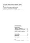
1
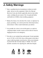
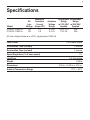
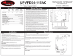
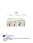
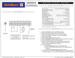
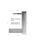
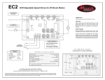
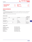
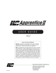
Models: C 1 X P 0 1 - 11 5 A C C 1 X P 0 3 - 11 5 A C C1XP03-D240AC USER MANUAL C1XP Series Copyright 2013 by Minarik Drives All rights reserved. No part of this document may be reproduced or transmitted in any form without written permission from Minarik Drives. The information and technical data in this document are subject to change without notice. Minarik Drives makes no warranty of any kind with respect to this material, including, but not limited to, the implied warranties of its merchantability and fitness for a given purpose. Minarik Drives assumes no responsibility for any errors that may appear in this document and makes no commitment to update or to keep current the information in this document. Printed in the United States of America. i Safety Warnings • Have a qualified electrical maintenance technician install, adjust, and service this equipment. Follow the National Electrical Code and all other applicable electrical and safety codes, including the provisions of the Occupational Safety and Health Act (OSHA) when installing equipment. • Reduce the chance of an electrical fire, shock, or explosion by proper grounding, over current protection, thermal protection, and enclosure. Follow sound maintenance procedures. • It is possible for a drive to run at full speed as a result of a component failure. Install a master switch in the AC line for stopping the drive in an emergency. • This drive is not isolated from earth ground. Circuit potentials are at 115 VAC or 230 VAC above earth ground. Avoid direct contact with the printed circuit board or with circuit elements to prevent the risk of serious injury or fatality. Use a nonmetallic screwdriver for adjusting the calibration trimpots. ii Contents Specifications 1 Dimensions 2 Installation 4 Mounting 4 Wiring . . . . . . . . . . . . . . . . . . . . . . . . . . . . . . . . . . . . . . . . . . . . . . . .5 Heat sinking . . . . . . . . . . . . . . . . . . . . . . . . . . . . . . . . . . . . . . . . . . .6 Line fusing . . . . . . . . . . . . . . . . . . . . . . . . . . . . . . . . . . . . . . . . . . . .6 Connections . . . . . . . . . . . . . . . . . . . . . . . . . . . . . . . . . . . . . . . . . . .7 Operation 8 Before applying power . . . . . . . . . . . . . . . . . . . . . . . . . . . . . . . . . . .8 Startup . . . . . . . . . . . . . . . . . . . . . . . . . . . . . . . . . . . . . . . . . . . . . . .8 Line starting and line stopping . . . . . . . . . . . . . . . . . . . . . . . . . . . . .9 Calibration 10 MAX SPD . . . . . . . . . . . . . . . . . . . . . . . . . . . . . . . . . . . . . . . . . . . .11 MIN SPD . . . . . . . . . . . . . . . . . . . . . . . . . . . . . . . . . . . . . . . . . . . .11 CURR. LIMIT . . . . . . . . . . . . . . . . . . . . . . . . . . . . . . . . . . . . . . . . .12 IR COMP . . . . . . . . . . . . . . . . . . . . . . . . . . . . . . . . . . . . . . . . . . . .13 Troubleshooting Block Diagrams Unconditional Warranty 15 18 inside back cover 1 Specifications Model C1XP01–115AC-A C1XP03–115AC-A AC Line Voltage 120 120 Maximum Armature Current (Amps DC) 1.0 3.0 Armature Voltage Range 0–130 0–130 Horsepower Horsepower Range Range w/ 120 VAC w/ 240 VAC Applied Applied 1/100–1/10 N/A 1/10–1/4 N/A AC line voltage tolerance is ±10%, single phase, 50/60 Hz Form Factor 1.05 at base speed Acceleration Time (no load) 1 second Deceleration Time (no load) 1 second Speed Regulation (% of base speed) Line Fuse Weight Dimensions Ambient Temperature Range 1% 5 A, fast acting 0.68 lb 5.50 in. x 3.50 in. x 3.20 in. 10°C – 40°C 2 Dimensions Figure 1. C1XP Dimensions Dimensions Figure 1. C1XP Dimensions (continued) 3 4 Installation Mounting • Drive components are sensitive to electrostatic fields. Avoid direct contact with the circuit board. • Protect the drive from dirt, moisture, and accidental contact. • Mount the drive away from other heat sources. Operate the drive within the specified ambient operating temperature range. • Prevent loose connections by avoiding excessive vibration of the drive. • Mount C1XP drives vertically or horizontally using the two mounting keyholes on the back of the case (Figure 2). The keyholes are 2.5 inches apart. For access to the keyholes from the inside of the case, remove the four case cover screws, lift the case cover straight out, and remove the fishpaper from inside the back cover. Leave the case cover removed to wire the AC line and motor to the drive. After mounting, remember to return the fishpaper to the inside back cover, as it provides necessary electrical isolation! Installation 5 Wiring • Use 16 AWG wire for motor and AC line voltage wiring. Shielding guidelines As a general rule, Minarik Drives recommends shielding of all conductors if: 1) wire lengths exceed 18 inches, with separation of power and logic leads; 2) wire lengths exceed 4 inches and power and logic leads must be bundled together*; 3) radiated and/or conducted noise must be minimized due to concerns about immunity or general compliance (CE, FCC, etc.) *Minarik Drives considers this an unfavorable condition and does not recommend bundling of power and logic leads for any length. If it is not practical to shield power conductors, Minarik Drives recommends shielding all logic-level leads. If shielding is not practical, the user should twist all logic leads with themselves to minimize induced noise. 6 Installation Under no circumstances should power and logic leads be bundled together. Induced voltage can cause unpredicatable behavior any electronic device, including motor controls. It may be necessary to earth ground the shielded cable. If noise is produced by devices other than the drive, ground the shield at the drive end. If noise is generated by a device on the drive, ground the shield at the end away from the drive. Do not ground both ends of the shield. If the drive continues to pick up noise after grounding the shield, it may be necessary to add AC line filtering devices, or to mount the drive in a less noisy environment. Heat sinking All C1XP series drives have sufficient heat sinking in their basic configurations. No additional heat sinking is required. Line fusing C1XP series drives come with two preinstalled fuses. Use fast acting AC line fuses rated for 250 volts, and approximately 150% to 200% of the maximum armature current. Installation Warning This product does not have internal solid state motor overload protection. It does not contain speed-sensitive overload protection, thermal memory retention or provisions to receive and act upon signals from remote devices for over temperature protection. If motor overload protection is needed in the end-use product, it needs to be provided by additional equipment in accordance with NEC standards. 7 8 Installation Connections ASSUMPTIONS: Minarik Drives’s drives supply motor voltage to terminals A1 and A2 (A1 is positive with respect to A2). It is assumed throughout this manual that the driven motor will rotate clockwise (CW) while looking at the output shaft protruding from the front of the motor. If the opposite is desired, simply reverse the wiring of A1 and A2 with each other. MOTOR ARMATURE Figure 2. C1XP Connections 9 Operation Before applying power • Verify that no conductive material is present on the printed circuit board. • Verify that the AC supply is properly balanced. Startup To start the drive: 1. Turn the speed adjust potentiometer knob CW to turn the power on (an audible “click” will be heard). The POWER ON LED lights when the power is on. 2. Rotate the speed adjust potentiometer knob clockwise until the desired speed is reached. 3. Turn the speed adjust potentiometer knob full CCW to turn the power off (an audible “click” will be heard). The POWER ON LED is extinguished when the power is off. 10 Operation Line starting and line stopping When AC line voltage is applied to the drive, the motor accelerates to the set speed. When AC line voltage is removed, the motor coasts to a stop. Line starting and line stopping (applying and removing AC line voltage) is recommended for starting and stopping in emergency situations only. It is not recommended for frequent starting and stopping. 11 Calibration C1XP Series drives have four user adjustable trimpots: MAX, MIN, CURR. LIMIT, and IR COMP. Recalibrate the trimpots if a different horsepower motor is used. All trimpot settings increase with clockwise (CW) rotation, and decrease with counterclockwise (CCW) rotation. Use a nonmetallic screwdriver for calibration. Each trimpot is identified on the printed circuit board. MAXIMUM SPEED IR COMP MINIMUM SPEED CURRENT LIMIT Figure 4. Calibration Trimpot Layout Calibration 12 MAX (MAXIMUM SPEED) The MAX trimpot setting determines the motor speed when the speed adjust potentiometer is turned full CW. It is factory set for 90 VDC (full load voltage).. To calibrate MAX trimpot setting: 1. Set the MAX trimpot full CCW. 2. Turn the speed adjust potentiometer full CW. 3. Adjust the MAX SPD trimpot until the desired maximum motor speed is reached. MIN (MINIMUM SPEED) The MIN trimpot setting determines the motor speed when the speed adjust potentiometer is turned full CCW. It is factory set to zero speed. To calibrate MIN trimpot setting: 1. Turn the speed adjust potentiometer full CCW. 2. Adjust the MIN trimpot until the motor has stopped, or is running at the desired minimum speed. Note: Check the MIN and MAX trimpot setting after recalibrating to verify that the motor runs at the desired minimum and maximum speed. Calibration CURR. LIMIT The CURR. LIMIT trimpot setting determines the maximum armature current output of the drive. It is factory calibrated to 1 ADC for C1XP01 drives, and 3 ADC for C1XP03 drives. To calibrate CURR. LIMIT: 1. With the power disconnected from the drive, connect a DC ammeter in series with the armature. 2. Set the CURR. LIMIT trimpot to minimum (full CCW). 3. Connect power to the drive. Push the speed adjust potentiometer knob to turn the power on. The motor should remain stopped. 4. Lock the motor shaft. Be sure that the motor is firmly mounted. 5. Set the speed adjust potentiometer to maximum (full CW). 6. Adjust the CURR. LIMIT trimpot CW slowly until the armature current is 120% of motor rated armature current. 7. Set the speed adjust potentiometer to minimum and remove the stall from the motor. Warning! Although the CURRENT LIMIT trimpot can be set to exceed the motor’s maximum armature current rating, we recommend you do not run the motor continuously beyond that rating. Continuous operation beyond the maximum armature current rating may cause thermal degradation of the motor and drive. 13 14 Calibration IR COMP The IR COMP trimpot setting determines the degree to which motor speed is held constant as the motor load changes. It is factory set for optimum motor regulation. To calibrate IR COMP (exact calibration): 1. Turn the IR COMP trimpot full CCW. 2. Set the speed adjust potentiometer until the motor runs at midspeed without load (for example, 900 RPM for an 1800 RPM motor) A hand held tachometer may be used to measure motor speed. 3. Load the motor armature to its full load armature current rating. The motor should slow down. 4. While keeping the load on the motor, rotate the IR COMP trimpot until the motor runs at the speed measured in step 2. Approximate calibration: If the motor does not maintain set speed as the load changes, gradually rotate the IR COMP trimpot CW. If the motor oscillates (overcompensation), the IR COMP trimpot may be set too high (CW). Turn the IR COMP trimpot CCW to stabilize the motor speed. Calibration Figure 5. Typical C1XP01 CURR. LIMIT and IR COMP Settings Figure 6. Typical C1XP03 CURR. LIMIT and IR COMP Settings 15 16 Troubleshooting Warning Dangerous voltages exist on the drive when it is powered. When possible, disconnect the AC line voltage from the drive while troubleshooting. Be alert. High voltages can cause serious or fatal injury. Before troubleshooting Perform the following steps before starting any procedure in this section: • • • • • • Disconnect AC line voltage from the drive. Check the drive closely for damaged components. Check that no conductive or other foreign material has become lodged on the printed circuit board. Verify that every connection is correct and in good condition. Verify that there are no short circuits or grounded connections. Check that the drive’s rated armature outputs are consistent with the motor ratings. 17 Troubleshooting Problem Possible Causes Suggested Solutions Line fuse blows 1. Line fuses are the wrong size. 1. Check that line fuses are 6 A. 2. Motor cable or armature is shorted to ground. 2. Check motor cable and armature for shorts. 3. Nuisance tripping caused by a combination of ambient conditions and high-current spikes. 3. Increase CURR. LIMIT setting. 4. Field circuit is open. 4. Send in drive to Minarik repair department. 1. Speed adjust potentiometer is set to zero speed. 1. Increase speed adjust potentiometer setting. 2. Speed adjust potentiometer connections are open. 2. Check that the speed adjust potentiometer connections are not open. 3. Drive is in current limit. 3. Verify that the motor is not jammed. Increase CURR. LIMIT setting. 4. Drive is not receiving AC line voltage. 4. Apply AC line voltage to L1 and L2. 5. Motor is not connected. 5. Connect motor to A1 and A2. Line fuse does not blow, but the motor does not run 18 Troubleshooting Problem Possible Causes Suggested Solutions Motor runs too fast at maximum speed setting MIN SPD and MAX SPD settings are too high. Recalibrate MIN SPD and MAX SPD. Motor runs too slow or too fast MIN SPD and MAX SPD are not calibrated. Calibrate MIN SPD and MAX SPD. Motor will not reach the desired speed. 1. MAX SPD setting is too low. 1. Increase MAX SPD setting. 2. IR COMP setting is too low. 2. Increase IR COMP setting. 3. Motor is overloaded. 3. Check motor load. Resize the motor if necessary. 1. IR COMP is set too high. 1. Adjust the IR COMP setting slightly CCW until the motor speed stabilizes. 2. Motor “bouncing” in and out of current limit. 2. Make sure motor is not undersized for load; adjust CURR. LIMIT setting. Motor pulsates or surges under load For additional assistance, contact your local Minarik Drives : distributor or the factory direct at 1-800-MINARIK. FIgure 7. C1XP Block Diagram 19 Functional Diagrams 20 Functional Diagrams Figure 9. C1XP Input Circuit 21 Notes 22 Notes Unconditional Warranty A. Warranty W - Minarik Drives warrants that its products will be free from defects in workmanship and material for twelve (12) months or 3,000 hours, whichever comes first, from date of manufacture thereof. Within this warranty period, Minarik Drives will repair or replace, at its sole discretion, such products that are returned to Minarik Drives, 14300 De La Tour Drive, South Beloit, IL 61080 USA. This warranty applies only to standard catalog products, and does not apply to specials. Any returns for special controls will be evaluated on a case-by-case basis. Minarik Drives is not responsible for removal, installation, or any other incidental expenses incurred in shipping the products to and from the repair point. B. Disclaimer - The provisions of Paragraph A are Minarik Drives’s sole oblication and exlude all other warranties of merchantability for use, express or implied. Minarik Drives further disclaims any responsibility whatsoever to the customer or to any other person for injury to the person or damage or loss of property of value caused by any product that has been subject to misuse, negligence, or accident, or misapplied or modified by unauthorized persons or improperly installed. C. Limitations of Liability - In the event of any claim or breach of any of Minarik Drives’s obligations, whether express or implied, and particularly of any other claim or breach of warranty contained in Paragraph A, or of any other warranties, express or implied, or claim of liability that might, despite Paragraph B, be decided against Minarik Drives by lawful authority, Minarik Drives shall under no circumstances be liable for any consequantial damages, losses, or expense arising in connection with the use of, or inability to use, Minarik Drives product for any purpose whatsoever. An adjustment made under warranty does not void the warranty, nor does it imply an extension of the original 12-month warranty period. Products serviced and/or parts replaced on a no-charge basis during the warranty period carry the unexpired portion of the original warranty only. If for any reason any of the foregoing provisions shall be ineffective, Minarik Drives’s liability for damages arising out of its manufacture or sale of equipment, or use thereof, whether such liability is based on warranty, contract, negligence, stict liability in tort, or otherwise, shall not in any event exceed the full purchase price of such equipment. Any action against Minarik Drives based upon any liability or obligation arising hereunder or under any lap applicable to the sale of equipment or the use thereof, must be commenced within one ear after the cause of such action arises. MINARIK DRIVES www.minarikdrives.com 14300 De La Tour Drive, South Beloit, IL 61080 Phone: (800) MINARIK (646-2745); Fax: (815) 624-6960; Document Number 250-0212, Revision 3 Printed in the U.S.A – August 2013