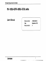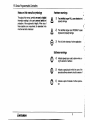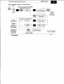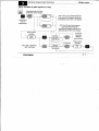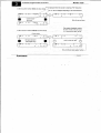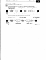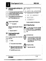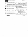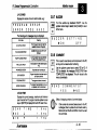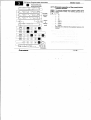
1
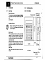
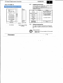
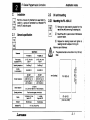
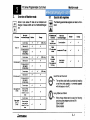
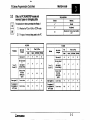
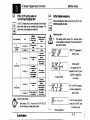
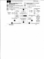
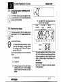
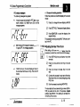
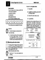
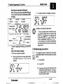
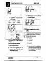
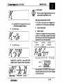
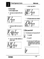
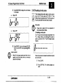
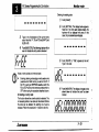
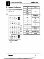
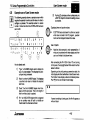
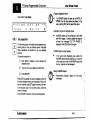
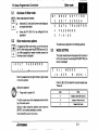
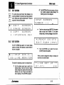
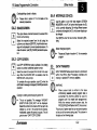
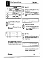
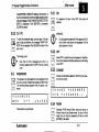
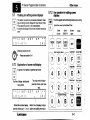
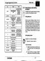
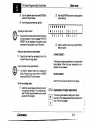
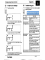
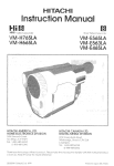
FX Series Programmable Controllers
Foreword
Thismanualcontainstext,diagramsand
explanationswhich will guide thereader in the
correctinstallationandoperation
ofthe
FX-1ODU-E and FX-PODU-E MMI unitsand
should be read and understood before attempting
to install oruse these units.
If in doubt at any stage during the installation of the
FX-1ODU-E and FX-PODU-E MMI units always
consult a professional electrical engineer who
is
to thelocal and national
qualifiedandtrained
standards. If in doubt about the operation
or use of
theseMMIunitspleaseconsult
the nearest
Mitsubishi Electric distributor.
This manual is subject to change without notice
AMITSUBISHI
Guidelines for the safety of the user and
protection of the FX-1 ODU-E and
FX-PODU-E MMI units
<
This manual has been written
to be used by trained and
competent personnel. This is definedby the European
directives for machinery,low voltage and EMC.
1
Fx Series Prwrammable Controllers
FX-lODU-E/FX-20DU-E
User's Manual
DU units
Manual number:
Date:
Manual revision:
JY992D54801A
September 1995
A
Fx Series Procyammable Controllers
manual's
this
Notes
onsymbology
Hardware
warnings
Throughout this manual,symbols are used to highm
information relating to the user's perswral 'safet3'and
protedion of the equipment's integrity. When any of
these symbols are encountered, its associatednote
must be read and understood.
A
A
@
.
1 ) The identifled danger WILL cam phyrkal and
property damage
2) identified
The
danger
could
POSSIBLY cause
physical and property damage
/
3) Point of furtherinterestorfurtherexplanation
'
.,
4
Software warnings
$,
4) Indicates special care must be taken when using this elementof software
@
a
5)
Indicatesa special pointwhich the user of the
assodate softwareelementshould be aware of
6) Indicatesapoint
tion
of interest or furtherexplana-
'
;
'
I
F X Seties Pnwrammable Controllers
Introduction
Installation notes
Monitor mode
User Screen mode
Other mode
Diagnostics
AMITSUBISHI
iii
lnff~ucfion
EX Series
Controllers
Programmable
1.
Introduction
1.I
Overview
Scope of this manual:
This manual gives details on dl aspecls d instahtbn
and operationof the FX-1ODU-EandFX-2MU-E MMI
units.
List of features:
1.2 Unit dimenslons
1.2.1 FX-1ODU-E
Retaining bolt,
Retaining b r a c k e t 1 M4 (o.,s)
Availability of features:
The listof features shownhereapplies
to the
FX-1ODU-E. Not dl thes~feahues are available
on the R(-SODU-E.
Monltor mode:
All PC word devices (timers (T), counters, (C) and data
registers (D)) can be monitored and their values
changed. allowed device ranges for changing values
may be set, and 8 preset devices may be monitored.
User Screen mode:
Displays user defined screen designs. These are taken
from the list of 25 user defined screens (0-24). The
programmable controller (PC) controls which screen is
displayed.
Other mode:
Used to create user defined screens and set unit parameters.
AMITSUBISHI
92 (3.62)
Connector
rnm (inches)
Weight: approx. 0.20kg
(0.44 Ibs)
1- 1
Controllers
Programmable
FX Series
1-5
Introduction
1.5.2 Connecting the D(-PODU-E
System configuration
15.1 Connecting the FX-1 ODU-E
The appropriate cableshould beconnectedbetween the
FX-1ODU-E andthe programsocket on the rear of the
ming port of the PC. Ensure the cab& has adequate
strain relief.
Fx,
-7
Fx2c
FX-2OP-CAB
(1.5m/59.1inches)
FX-POP-CADP
FX-2OP-CAB
FX-2OP-CAB0
(1Srn159.1 inches)
AMITSUBSHI
The cable connecting the FX-2ODU-E is inserted into
the connector under the cover on the rear of the unit.
Use the supplied cable grip to provide strain relief.The
supplied cable holdersare used to route thecable from
the PC to the DU unit.
Fx[ lODU
-E
Fx,
I
Fx2c
7
M-PODU-CAB
(3.0m/ll8.1 inches)
Fx-
E-
20DU
-E
M-2ODU-CAB0
(3.0m/I 18.1inches)
1- 3
EX Saries
Controllers
Programmable
1.6
Introduction
How to use this manual
Tohelpidentifywhichpartsofthismanualapp~towhich
DU units, the
folkwing indicator is & ~ $ ~ d with
e d relevant
section tiles:
t
-
Shaded bwes indicate
the applicable DU types
"10": FX-1ODU-E
"20":FX-PODU-E
Throughout this manual, CAPITALLETTERS are used
to refer to items whi& are displayed
on the screen of the
DU unit. These items are sometimes abbreviated
on the
DU saeen.
1.6.1 Symbols usedto indicate operation keys
A word endosed in square bradtets0 indicates theDU
key of the same name.
1.7
Note onthe FX-1 ODU-E's memory
This unit USBS EEPROM memory. This memory may
have data rewrittento it up to about 100,000 times.
The EEPROM allows the unitto resume operation from
the last screen displayed before a power down. This is
the resumefundion.
AMITSU~SHI
I- 4
Installation notes
Programmable
EX Controllers
Series Programmable Controllers
2.
Installation
Both DU units are only intended to be used when installed in a panel and connected to a Mitsubishi Fx
family PC inside the panel.
2.1
General speclficatlon
wn-
P.nmt.r
FX-1ODU-E
FX-2WU-E
I
2.2 DU unit mounting
2.2.1 Mounting the FX-lODU-E
R
A
7) Remove the metal retainingbracket from the
mar of t h e unit by removing its retaining bit.
2) Mount the untt In a panel cutout of dimensions
as shown bebw.
3)
Replace the retaining bracket and tighten its
retaining bolt with atorque of 3-5 kg.cm.
Maximum panel thickness:
The panel should be no more than4 mm (0.16 inch)
thick.
mm (inches)
FX-1ODU-E
2 k a u s i n k l di tl K
dX
U .rYS i n & a a 7 d X , Y
andZdirectioos)
and z die3b-r.)
1
87 4 - 0 . 5
(3.43+o/-0.02)
4
ApDlicable PCS
A MMUBlSHl
2- 7
lnstallatlon notes
2.3
2.22 Mounting the l9C-20DU-E
1) Make the panelcutout to the dimensbns shown
bebw, and drill the four mounting holes
2)
Insert the unit into the cutout. A washer, spring
washer and nut should be fitted on each of the
four retaining b
o
k If the panel is thin, a bush
should also be used.
FX-20DU-E data wrlte PERMfTlFORBID
switch
This switch is located next to the connecting cable
socket on the rear of the unit. To gain access to it,the
cover on the lower rear part of the unit should be reThe switch has two positins
PERMIT PC data may be monitored and changed.
-1
FORBID: Access to PC data is restricted. This has
the same effect as using a B or C entry codein the
PC.
Edge
of
unit
front
Effect of PC entry codes:
I
I
I
I
FX-PODU-E
a
When the unit is switched to PERMIT, the ability to
monitor and change PC data is restricted by any
entry code already inthe PC.
PC entry codes:
9
-I-
,
%:I
information,
;; please
see Chapter 3,
2- 2
Fx Series Progmmmable Controllers
Overview of Monitor mode
3.
*.go,
MonitormodeallowsPCdata
to be monitored and
changed. Devices which can be rnonitored/changed
are:
R e m to b.
monltomd/clungN
PCd-
Monitor mode
3.1
Special data registers
The following special data registerscan also be rnonitored:
m
g
r
Yonltor
liner (T)
6 tit Carnter (C)
2 tit carnter (C)
Use of the real time clock:
The real time dock faciliiy is provided by installing
a real time c l o d cassette, or a memory cassette
with this feature inthe PC.
I
vabe
I
vabe
I
AMITSUBISHI
I
d
Using D8040and 08049:
Before these devices can be used, thefollowing
special auxiliaryrelays must be set ON:
d8040:M804708049:M8049
3- 7
I
.
Fx Series Programmable Controllers
3.2
Monitor mode
Effect of PC RUWSTOP modeand
memory types on changlng data
I
The tables shown here summarise the efffstsof:
1) Whether the PC is in RUN or STOP mode
2)
J
X
I
p
w
l
Ndevwed
I
The type of memory being used by the PC
PC STOP
1
PC RUN
I
E(
3.3
F
Series Programmable Controllers
Effect of PC entry codes on
monitoringlchanging data
3.4
If the PC already has an entry code set, this will also
affect what data can be monitored and changed. The
.___.
.. table below summarises t h e conditions.
I
I
Monitor mode
md.None
Mne
w excspt:
Initial dlspl8y sequence
A
After cormbding the cable and turning on the PC, the
fdkwrclg displays are seen.
Resume fundion:
The display before poweroffisresumedwhen
normal operationis reached. This can be held for 3
days withoutpower.
about 2 secs
I
I
Entering entry codes:
See section 3.10.7. Note thatthe FX-1ODU-E
cannot change or delete entry codes.
AMITSUBISHI
i
"PROG-ERR".
If a program erroris
deteded in the PC, push
CLEAR to display the
errm code.
[CLEAR]
Push
/R- - - -j
"PC-X.XX",PC's version
number, displayed for
about 2 sea.
1
Normal operation
If an "A"entry code has
been set in the PC, k e y
in the entry code.
3- 3
',
4
Fx Series Programmable
Controllers
Monltor mode
,
5) 16 b R data register rnonibr/current value change (up
to two can be displayed on one saeen)
of new value \
Current
value
Entry
1 0
M b D
K l O O O
1 0
S b D
K
-
I
6)32 bit data register(D+1 and D) rnonitor/wrrent value change
M b D
5 1
D
5 0
K 2 5 6 0 0 0
'
.
3.7.2
1) Timer wrrent value display (16/32 bit counters and
data registers are the m e ) . FWh [SEITING] to see
the set value,
0 COUNTER
0 DATAAEG.
0 STATE
K
5 1
of new value'
DEVICE
*
*
AMITSUBSHI
,
I
2) 16/32 bit counter indired setting display (timers are
the same). Push [MONITOR] to see the current value.
0 SElTNG
0 TIMER
0 DATAREQ.
0 MONITOR
0 COUNTER
0 STATE
mYSlUTlbEwllvALK
(Display shows
TlOs current
value is 26.4s)
5 0
K
Entry
value
Current
FX-PODU-E screen displays
0 TIMER
S b D
0 SETTING
0 MONITOR
mysl~1yTlllvuYE
(Display shows
C1'sset value
stored in 03)
DMCE
CLOCK
.
3- 10
Monltormode
EX Series Programmable Controllers
3.9
S ecialdataregistermonitoringonthe
&-I
OD"-E
This feature allows special data register informalion to
be accessed. Thisallowsthe display of such information
as real time dock data andadive states.
These data registers can
be monitored directly by pushing the "E" key and seleding from a menu.
Explanation of special data registers:
b 1 . R
2 . A
3 . A
4 . P
5 . B
6 . C
T
C
N
C
U
O
C
T 1 V E
S T A T E S
N U N C I A T O R
D l A G N O S T .
Z Z E R
M M E N T
The options are explainedin the following sections.
Please referto sedion 3.1
Explanation of special data reglster monitoring on the
FX-PODU-E
Please refer to sedion 3.10
3.9.2 RTC (Real Time Clock)
This provides a display of the current time and date
information. This information can also be displayed by
the TIME and DATE objects available in User Screen
mode
Use of the real time clock
a
TO access this fundion, the DU
mode.
Monitor
Unit
must
first
be in
0
1 ) Push [El
2)
The menu shown to the right is displayed.
3)
Select anoption using the up/down cursor keys
md [ENTER], or diredlyby entering its number.
TM real time do& fadlay is provided by installing
real atime dock
or cassette
memory cassette
with this feature In the PC. When a FITC facility is
available, M8018 i
s ON.
RTC operation and setting:
0
Pleaserefer to section 3.8.3
4) Push [CLEAR] to return to the menu.
AMITSUBUHI
3- 13
Monitor mode
EX Swbs Pmgmmable Controllets
Example operation:
The RTC timedisplay looks like this
'
\
9 5 / 0 7 / 0 7
1 3 : 4 6 : 4 6
F R I
While the clock display is present, pushing [ S 5 J then
[ENTER] roundsthe display to the nearest30 seoonds
If no RTC cassette or memory cassette containing this
feature is fitted, then this error message is displayed:
N O
O N
3.9.3
To enter the date and time Tuesday, July 25th 1995
17:00:00, key in this sequence:
191 151 101 VIM (51121
111 VI 101 P
I101 P I
Entering days of the week:
Days of the week are identified by numbers:
7) Push [SET]t w i c e .
a
2) Type in the currenttimeanddateusing
3.9.4 ACTIVESTATES
C L O C K C A S S E T T E
F X
P C
Adjusting the Real Time Clock
the
number keys. The cursor automatically moves
along as each part of
the new setting is entered.
Single figures (e.g. '07" in the example above)
should be prefixed with a zero.
3) Usetheup/downcursorkeystoskipitemswhich
do not need changing.
4) Push [ENTER] to finish. The clock will then start
from whatever seconds value was entered.
AMITSUBISHI
0
SUN
~
~
~~~~~~~~~~~~~~~
I
1
MON
I
2
TUE
3
I
WED
~~
I
4
M U
5
I
~~
FRI
I
6
SAT
~
Date format:
Notethat this display has afixeddateformat.
However, the format of the DATE object in User
Screen modecan be set by the user.
Incorrect clock setting:
Anincorrect dock setting will notbeaccepted by
the unit (e.g. setting a month > 12 etc.).
This display shows the lowest currently active states
when the PC is running a SFC step ladder (STL) program. Thisfundion is equivalent to monitoring the speaal data registers DE040 to D8047.
Before this functioncan be used, special auxiliary relay
M8047 must be on. If not, this error is displayed:
M 8 0 4 7
N O T
3- 14
O N
Monitor mode
EX SensesProgrammable
Controllers
2. PC ERROR
Displays the nature of an error andits code, e.g.:
P R O G R A EM R R O R
E R R O R
C O D E :
I
I
Turnthe audible key feedbackON/OFF. Use the
up/*
cursor keys to sled,then [CLEAR] to return
to the menu.
6 6 0 2
The folbwing error messages may be displayed:
Ermr-
3.9.7 BUZZER
MWnn
I
( B U Z Z E R
I
S E T T I N G
.ON
O F F
1
I
3.9.8 COMMENT
This is used to read device comments stored in the PC
so they can be viewed when monitoring.
Use the up/dwn amor keys to select YES OT NO. If
YES is seieded, the messages 'EXECUTING'then
'COMPLETED' are displayed. The unit returns to the
menu automatically.
3.SCAN TIME
Displays the current average, maximum and minimum
scan times for the PC program.
Use the up/dwn cursor
keys or [ENTER] to dsplay MAX and MIN scan times.
~
S C A N
M A X
MI N
T I
4
-r
M E
1 .
1
.
1 .
8 rns
Q m s
7 m s
I
R E A D
C O M M E N T S ?
Y E S
,NO
I
Effect of changing numberof comment blocks:
If the number of comment bbdts stored in the PC
is changed, then to update the comments read by
h DU unit, turn the DU unit off then on and reread
the comments.
w
Monftafmode
FX SetiesControllers
Programmable
3.10 S ecial data register modbring on the
1-1
&-PODU-E
The FX-20DU-E allows spedal data registers containing such information as real time dock data and adwe
states to be diredly accessed.
I-I-
c
4) Push NONITOR1.A dodc displaysimilarto the
one shorn here ts displayed.
0 TIMER
0 CWNTER
3.10.1 Real tlmedock dlsplay
0 DATAREG.
0 STATE
I
This feature allows the FX-PODU-E to dimiav time and
?@.*a
date information. Ifan FX PC isusod, it
later.
&
s
tbe V 2 . 0 ~
Use of the real time clock:
The real time dock faciilty is provided by installing
a real time dodcr;assette 01 a memory cassette
with this feature in the PC. When a RTC facilityis
available, M8018 is ON.
Use the following procedureto show the real timeclock
display;
7)
Push [CLEAR]
2)
Push [ S H i m
3) Pushkey IS), wblch h a s C K " (CLOCK) hart&
in its top @h!hand comer. The following&play
appears to $how the RTC fundion has been
selected:
CLOW
I
.
m
I
a'
0 SETTLNG
0 MONITOR
i
I
I
This example display showsthe date Monday,Jufy 10th
1995,416 p.m. Note that the day is shown bya flashing
dot above the releant day marker beneath the upp&
display. On the lower display, thecolon flashes to indicate seconds.
Seconds dtsplay
Push [+I or [-1 to toggle the bwer displaybetween
HH:MM and MM:SS.
1
Monitor mode
Programmable
Controllers
I% Series
RTC dhplay meurges
The following messages may appear:
If invalid values were entered for RTC d a t a , (e.g. a
month number >12), M8019 turns ON, and this
message appears:
+I- 30 second roundlng operation
-
Follow this procedure to round
the display to the nearest
minute:
7) Push [+I
to change the lower display to MM:SS
2)
Push [SETTING]. Theseconds displayflashes.
3)
Push (MONITOR] to round the display to the
nearest minute.
This o p e r a t i works by pulsing Ma017 (Minute rounding) in the PC.
M8018 being ON indicates the presence of a RTC.
If it goes OFF, this message appears:
3.10.2AdjustIng the Real Time Clock
Afler calling up the real time dock display, follow this
i g:
procedure to correct the arrent date and timeSetn
1) Push [SETTING]; the year flashes. Key
2)
If M8016 turns on, the clock display is frozen, but
the dock itsetf continues running. This is the LAP
display:
3)
new year.
in the
Push [+] to move to the month. Key in the new
month.
Push [+] to move to the date. Key
date.
in the new
4) Continue MIS process for each part of Me data.
5)
Skip items which do need
not changing bywing
the [+I
key.
End the process by pushing [MONITOR]
The clock starts at the setsecondsfigure when [MONITOR] is pushedat the end of the process Special
auxiliary relay M8015 (Time setting) is adbated momentarily by this process.
AMITSUBISHI
3- 18
Monitor mode
EX Series Programmable Controllers
Exampk operation:
To enter the date and time Tuesday, M y 25th 1995
17:00:00, key in this sequence:
V I 191 [91[51[01 m M [51[21
111 m [Ol [Ol 101 I01
1
1
1
2
1
3
1
4
1
5
7) Push[CLEAFl]
t
1
2) Push [DNICE +] or [ D N I C E - ] until the STATE
3)
Entering days of the week:
Days of the w e e k are identified by numbers:
0
Procedure for monitoringstab numbers
LED indicatorcomes on.
Enter the STL branch number, [ l ] to [e].
4) Push[MONITOR].
1
6
The correct day can
also be selected withthe [-Ikey.
Date format:
Note that this display has a fixed date format.
Incorrect do& setting:
Anincorrectclocksetting will not be accepted by
theunit(8.g.setting
a month > 12 etc.).After
pushing plONITOR], the incorrect valuewill flash.
Corred the value and complete with (MONITOR].
A display similar to the one below wiy be seen. In this
example,branch1 was selected,and state S105 is
arrrently a d i e within this branch. U s e the [ D M C E
+VIDEVICE -1 keys to access other branches. If no
a~~statesarepresentinabranoh,'OR'isdisplayed
0 TIMER
0 COUNTER
0 DATAREG.
0 SFITING
0 STATE
0 MONITOR
oMII**Ie6mvyuE
Currently active statein
the selected branch
-JU
3.10.3Monitorlng actlve state numbers
Thk display shows the lowest currently active states
when the PC is running a SFC step ladder (STL) program. This fundkn is equivalent to monitoring the spedal data registers D8040to 08047.
Effect of entrycodes on state monitoring:
a
Note that an "A' entrycodepreventsstate
monitoring.
AMITSUBISHI
3- 19
*,
Monitor mode
Fx Series Prclrgrammable Controllers
Monitoring two branches oimultaneousty
While monitoring one branch, push WONlTW again.
its a d i state is added to
The next branch number and
the display
0 TIMER
0 DATAREG.
0 SE'ITING
0 MONITOR
mlg1yNBnw3vyuL
If no states are active, this message is displayed:
c I'
Conditions onthe us8 of the state monitor:
Currently active
Branch 2
CLOCK
To return to single state monitoring, push [MONITOR]
again.
State monitor display messages:
The following messages may appear:
Before this fundion can be used, special auxiliary
relay M8047 must be on. If not, this error is
displayed:
1. The minimum state number in the
flow of branch
n+l should be larger than the maximumstate
number inthe flow of branch n. For example, if the
higheststate number in branch 3 is S30,then
branch 4's lowest state numbershould be 230.
2. There should be r#) more than 8 branches and
each branch should only have one active state at
any given time.
3.10.4MonRoring annunciators
This dispiavs the lowest currently active annunciator
(states SSOb to S999).Follow thisprocedureto use this
feature:
1 7) Push [CLEAR]
2) Push [ S H I V
3) Push key[O], which has "AN" (ANNUNCIATOR)
marked in Its top right hand corner. The folbwing display appears to show the annunciator
fundion has been seleded:
If M8049 is ON, but all annundators are OFF, then
this message is displapd:
4) Push [MONITOR] . A display similar to the fol0 TIMER
lowing will appear:
0 DATA E O
'-,
0 SElllNO
I
1
t
3.10.501 lay of programmablecontroller
sta8pus
I
I
I
I
I
In thisexample, S900 isthelowestcurrently
annunaator.
Annunciator monitor drptay messages:
The following messagesmay appear:
If specialauxiliaryrelay
I
adive
M8049 is OFF, the
annunciator monitor will not function and the
following message is displayed:
hlTSUBSHI
This feature allows some preliminary diagnostic work
to
be carried out in bothnormal and PC fault conditions.
When the PC is running
normally:
Follow this procedure:
I
1) Push [ C W R ]
2)
Push [SHIFIJ
3) Push [l], which has"PC" (Programmable Con-
troller) marked inthe top right hand corner. The
followingdisplayappeaFptoshawthediPgnostic
fundion has been sebded:
3- 27
.!
R(
Sohm-able
Monitor mode
Controllers
Low battery signal:
When the battery vottage falls bebw the low limit,
spedal auxiliary relay M6005 turns O N .
When an error has occurred in the PC:
The FX-20DU-E can produce error messages for errors signalled by the followingspedal auxiliary relays:
4) Push [MONITOR]. If there are IK) PC errors,one
of the following displays wil appear:
M8005,M8009, M a 6 1
PC in RUN mode:
~~~~
Ma063 to M8066
To see the error messages, followthe same procedure
as before. If an error exists, a display like the example
below will be seen. Note that the lower display glves
the
associated error code, where appropriate.
~
PCinSTOPmode:
Push [DEVICE +] OT [DEVICE -1 when the RUN/STOP
display is present to toggle the battery voltage display:
I
I
Battery mttage
Present value
AMITSUBSHI
LOW
limit
I
CLOCK
DMCE*
E
I
-777
l
I
Push the [DEVICE +] or [DEVICE -1 key to move forwards and backwards through the
list of error messages
if more than oneexists
3- 22
.
Fx Series Progmmable Controllers
Error display messages:
The following messages may appear:
Communicationerrorbetweenthe
PC
20DU andthe
~1
Monitor mode
e
Low battery witage: M6005 ON.
I I I
1-1-
24VDCpbwertoextensionunitsdown:MB009ON.
.
PC hardware error: M8061 ON,errorcode 6101 to
6103
3.10.6Key buzzer ON/OFF
Follow this procedure to turn the key buzzer
ON or OFF:
Programerror: one of M80W to M8066 ON, error
code 6401 to 6608
hlTSUBSHI
u
1) PushICLEAR]
2)
3)
Push [SHIm
Push [2], which has "BZ" (BUZZER) marked in
the upper right hand corner. The following displayappears to show thebuzrerhasbeen
selected:
3- 23
Fx Series Programmable
Controllers
4) Push [MONITOR] to display the current status
of the buzzer:
Buzzer
ON:
MonHor mode
3.10.7Handllng of entry codes
The 8 character entry code is used to restrict accessto
data in the PC when using the FX-20DU-E. Three
different levelsof protection exist The first character of
the entry code determines what level
is selected.
Entry codes
Buzzer
OFF:
Pleaserefer to section 3.3foranexplanation of
entry codesand their effects
1) Releasing anenby code
If an "A" type entry code has been programmed in the
PC, a display similar to the following will be seen at
power up, after the 'SET UP" and PC version number
displays
5) Push [DEVICE +I to turn the buzzer ON, [DEVICE -1 toturn it OFF. Finish
bypushlng PONI-
TOR].
Buzzer operation:
0
-
When O N , the buzzer swnds each time a key is
pushed, and three times when an erroneous
operation is attempted.
Follow this procedure
to releasethe restrictions imposed
by an entry code:
1) Push[CLEAR]
2)
Push[SETTING].
pears:
The followingdisplayap-
I
------.-
Deleting the edsting code:
I
7) Push[CLEAR]
2)
.
Push[SETTING]. The display belowappears.
Note that if no entry ax% exists already, the
hyphenswillbereplacedwithzeros:
In this
c a s e , this proceduredoes nat apply.
------
3) Type in the 8 characters of the currententry
code. Note that "A", "B' and %'am [SHIFIJand
[419151 or (61.
4) Push fMONITOR].Thefdlowing display w i l l be
seen to indicate the entry codeis released.
3)
Push [DEVICE -1. 'DEL"appears to the left.
Type in the code.
r
Notes on entry codes and memorytypes:
Entering, deleting or changing an e n t r y d e is only
possible when RAM memory is used on the PC. If
the PC is using an EEPROM cassette, switch the
PC to STOPand turn the memory protect switch to
OFF before usingthe procedure described above.
2) Deleting an entry code:
This function allowsthe current codeto be deleted. This
is necessary beforea new code canbe entered. Before
the codecan be deleted, the existing one must be
released. Follow the procedure in 1) above to do this.
4) Push IMONITOR]. The display changes to that
shown M
o
w to indicate the wde has been
deleted.
EX S&m Programmable Controllers
If an kroorred code is entered, 'Err"is displayed:
3) Enterlng a new entry code
This fundion allows a new code to be entered. Before
the code can be changed, the existing one must be
released, then deleted. Follow the procedures in1) and
2) to do this.
To enter the new code:
7) Push [CLEAR]
2)
3)
Push [SETTING]. Thedisplayshown belowappears. Note that if hyphens appear instead of
zero$ an entry code akeady exists and this
procedure cannotbe used.
Push[DEVICE +]. "SET"appears to the left
Type in the new code.
Monitor mode
4) Push [MONITOR] to register the new code.
Fx Series Programmable
Controllers
3.1 1 Preset monftortng functlon
The preset monitoring function
providesNo methodsfor
limiting the number of *ices ~ i c han
. operator can
change the set v a l u e s of. The q
o
u
n
t d lccsss is set
at the design stage using one'or bothsf t b following
functions:
Preset range mon1toring:Upto 8 presetaccess
ranges for Timers, Counters and Data Registers
iTC, Dl.
Preset device monltoring: Up to 8 nominated
devices selected from T,C, and D.
Operation ofthe preset monitoring functions:
Note that these functions only restrict the devices
for whichset values can be changed. It isstill
possible to monitor other devices not affected by
these presets.
Conflicts between preset monitoring functions:
If oneof t h e devices setusingthepresetdevice
monitor falls outside the rangeof the preset range
monitor (whenboth are being used), thenit will not
be possible to change itss e t value.
Attempting to change the set value of a device not
induded in preset monitor functions (when
used):
This is notpossible. The error " D N OUT OF
FLANGE" is displayed.
AMITSURWI
Monitor mode
3.1 1.1
Setting the preset rangemonitor
function:
Begin by holding down the [CLEAR] key while turning
on the power. Adisplay similar to that below wiU be seen:
'A":All devicesaccessible,factorysetting(ENABLE
SETTING)
"E": Set preset device range (RANGE SETTING)
"F": A l l preset device ranges disabled (FORBID SETTING)
A
E N A B L E
( E : R A N G E
S E T T I N G
F : N O N E )
Entering "A" or "F"returns to the normal Monitor mode
screen.Entering "E" allows the devicerangestobe
preset:
7) lnplrttherangenumber,l to8.Theup'dcmnarrsw
keysoanalsobeusedtomowbehveentheranges
2) Type FIMER q,[COUNT. C] or [D.REG DDD]
to enter the device type for the range. Note that
3)
32 bit (DD) word devices cannot be selected.
Enter the lower lknlt and push [ENTER]
4) Enter the upper limit and push [ENTER]
5)
Repeat for each range
6) Finish by pushing [B]
The [Dl and [ENTER] may be used to delete a range,
and data entrycan be cancelled by pushing [CLEAR].
3- 27
Monitor mode
Fx Series Programmable Controllers
3.1 1.2setting the preset device monitor
functlon:
Begin by holding down the PETI key while turning on
the power. A display similar to that bekw wtll be seen:
"C": Preset device monitorOFF, factory setting (PRESET DISABLE)
C
P R E S E DT I S A B L E
( E
M O N l T O R )
"E": Preset device monitor ON (PRESET
MONITOR)
Entering "C" returns to the normal Monitor
mode screen.
Entering "E" allowsthe required devicesto be preset:
Inputthepreset
device number,l to 8.The
up/down cursorkeys can also beused to move
between the preset devices.
3.11.3Example operation of the preset range
monitor function
The example on the next page gives a guideto setting
up preset monitor ranges.The following ranges will be
set:
TOtoTl9
COtoC4
D l 0 to D29
D8013 to 08019
Note that this is half the maximum number of ranges
available.
Before [e] is pushedto register the data, the settings can
be checked by using t h e up/down cursor or [l]-[8] to
move throughthe list.
Type VIMER r], [COUNT. C]or [D.REG D/DD]
to enter the devicetype to be preset.
Enter the device number and push [ENTER]
Repeat for each deviceto be preset
Finish by pushing [e]
may be usedto delete
The [Dl key followed by [ENTER]
a range, and data entry can be cancelled by pushing
[CLEAR]
hITSuslsHI
-
.
.
..
.
.
,
.
3- 28
...
Fx Series Programmable Controllers
Monllor mode
I
MEMO
.
R(
4.
-
Series Pmgrammable Controllers
Overview of User Screen mode
User Screen mode
albws the display of up to 25 (0-24)
user defined screens.These are defined using the FX1 ODU-E itself in Other mode.The size of these screens
are:
Screen#O(defaultscreen):l6charactersx16llnes
0
Screens #1-24: 16 characters x 4 lines each
The physical displaysize is 16 characters x2 lines.
Each screen may contain text and a number of other
objects, listed below.
4.1
.. ...
,
Objects availablein User Screen mode
The following objects are available:
,
.,
,
User Screen mode
2. Screen objects
T
NUMBER
INDICATOR
TEXT
INDICATOR
llME
DATE
I
1. Text:
SWKCH
NAME
I
SCROUJNG
1
AMITSUBISHI
4- 1
.. ..-~
..
.. .
.
User &reen mode
Fx Series Programmable Controllers
Limit on numberof objeds per screen:
For saeen #O, a limit of 4 display objects per two
lines applies.
B
4.2
Examplescreendisplay(screen #O)
As only two lines are visible at time,
one the w e e n must
be saolledto see all of the 12 lines of the display.
Display of objects during screen creaUoWediting:
During this process, the objeds are displayed as a
'P" followed by one
a r m for each further character
space theobjed occupies.
11
13 (4 16 (6 17 18 19 ~ 1 0 ~ 1 1 ~ 1 2 ) 1 3 / 1 4 ~ 1 6 ~ 1 6
l - * * L i
N EM O N l
T O R * *
2 - 1 C o
n d 1 t I o n : P b b b b b k a
3 S h l f t
T o t a i : P b b b
6 * *
6 - 1 :
7 2 :
Dl A G N O S T I C S
9 - 4 :
I O - * *
C
O
P
a
-
11
12
I3-
011
D o o r
h
P
u
c
u
E
s
k
P r e s s u r e
P
O p e n
t eJ a m
R A T I
h
' A
n o w l
m e d
O N :
'
e d g e 1
I
P
t
t
Key to objects used:
1) TEXT INDICATOR: in this c a s e , show s"N0RMAL" whenits bit device k OFF, "FAULT" when
its bit device Is ON.
2)
4.3
NUMBER: Displays the data registervalue representing the total produced this shift. A second
for
NUMBER object reads another data register
the "Hourly Total".
3) INDICATOR: A black square is displayed when a
bit device mrrespondingto the f a u P changesstate.
4) SWITCH: Pushing key [A] controls a PC bit device.
5) The dotted lines indicate unused lines (for clarity
only; not displayed by the unit).
AMITSU~~SHI
Screen change method
The saeen displayed by the DU unit is determined by
the value in a PC data regktec (default;DO). This is the
SCREEN REGISTER.
Devices used:
DO: D a h register containing the w e e n number to
display (KO-24).
Dl: Reserved. Do not use.
c
4-2
,
-.
,
-.
I
4.4
Changing the default SCREEN
REGISTER:
R
Please see Chapter 5, section 5.4.4
Si-/
w%.;
Program example
The folbwing example demonstrates how to change
which screen is being displayed.
MOVP
K20
...,.
,
Fx Series ProgrammaMe Controllers
,
,
,
User Screen mode
Screen
scrolling
method
This is controlled by the SCROLLING object on each
ween. Scrolling is activated from the DU's keypad by
using the up/down w m r keys. The options are:
7) SPLIT top line fixed, bottom line scrolls line by
line through restof screen
=
1I
/
2) LINE: Each press of the cursor keys scrolls the
whole Screen one line up or down.
When XOOO turns ON, the value 5 is moved into DO.
Hence the DU unit will dlsplay screen number 5 .
When X001 turns ON, the value 20 is moved into DO.
Hence the DU unit will display screen number 20.
3)
Selectina scleen numbers:
L
Onty defined screens can be seleded. Writing the
number of an undefined screen to the SCREEN
REGISTER will cause the DU unit to display the
message "NO SUCH SCREEN".
two lines upor
Limits on saolling:
Programming information:
Please see the programming manual
for
you are using.
SCREEN:Scrollthescreen
down, one physical screen.
the PC
The
screen can scrolled to the
last
line
which
has
defined objects For SCREEN, this may leave a
blank line at the bottomtheofscreen as it is scrolled
in line pairs
User Screen mode
Controllers
4.5
Key functions in User Screen mode
The FX-1ODU-E's keypad has the following functions
Jumeric
keys
SWITCH object kerj
AMITSUBSHI
I
0-0
I
MON. ENTER
I
Numerc mby
I
Enter new babes
I
J
4-4
FX Series Progmmable Controllers
4.6
Usermode
Screen
Example use of User Screen mode
5) Pushing [C]adivates another audliiry relay via
The folkwing example shows a sample screen whkh
requires the operator to entera set of values in order to
configurea plocess. The example sueen is meen
number 1 and so has four lines. SCROLLINGhas been
set to LINE.
T y p e : 2 B7 a t c 1 h 2
S o a k : 4 , O s e c
E
r
r
:
a SWITCH object
to indicate the setting process
is complete.
Displaying timer and counter values:
If S€fTING value is chosen for a timer or counter
which does not exist in the PC program, question
marks will be displayed instead of a value.
Use of o b j d s
l
v
Key toob@&
After connecting the FX-IODU-E to a PC and turning
on the power, the copyright Screen then version number
screen is shown.
Depending on the unl's previous powered
on state, the
initialdisplay will either
be Monitor or User Screen mode.
The Monitor mode display is shown immediatety below.
Push [Fl for the User Screen mode display.
used:
'Type"; a NUMBER objed used to display the
value in adata regkter. This displays the produd type being processed.
"Batch": anotherNUMBERobjed. This displays
a counter's set value to indicate the required
batch size.
"Soak?; the third NUMBER object which displays a timer's sat value. This is the length of
time for which a batch
is soaked.
"Err"; an INDICATOR objed which is triggered
by an auxiliaryrelay (M coil)toindicate
an
invalid soak timehas been entered.
Notethat this example is onlyrepresentative of
what can be achieved with these& i d s and their
use is not limited to that shown
here
I"
If preset monitoring is being used,the M will appear as
white on black
4-5
...
Fx Series Progmmmable Controllers
Changing displayedvatu&:
User sueen mode display:
* * L I N E
S E T - U P
T y p e :
0
B a t c h :
* *
0
4.6.1 Key operation
The following sectionwill explain the key operations for
that
entering data on this user defined screen. Note
these operations arecommon to all user defined
screens.
The general procedure is:
1) Push [SET]to displayacursorbeneaththe
displayed value
2) Type the new value ushg the numeric keys
3) Push[ENTER]
When [SETJ is pushed, the cursor will appear under the
be changed. If this is not
first value displayed which can
the one required, push
[S- again to move to the
ned.
If the required value is not currentiy visible, scroll the
screen to display it.
Push [CLEAR] to cancel an incorredvalue/operation.
AMITSUEUSHI
User Screen mode
If a NUMBER objed has been set to WRITE IN:
FORBlD, then its value cannot be altered. In this
case, pushing [SEI win not select thls objed.
Acceptable ranges for displayed values
NUMBER objects can be configured to have MIN
and MAX ranges I f a value outside this range is
entered, the message 'OUT OF RANGE' is
dlsplayed. Push[CLEAR] and try again.
NUMBER object display capacity
If the valuebeingdisplayedgoesoutsidethe
NUMBER object's display capacity (e.g.. becomes
a three digit value when the NUMBER object only
has two),asterisks will be displayed.
Setting NUMBER objects:
Please refer to Chapter 5, section 5.7.4 for further
information,
4-6
i
R( Series Pmratnmable
5.1
Controllers
Overview of Othermode
1 b 1 . M O D ES E T T I N G
2 . E D 1 T
S C R E E N
Allows the DU unit's User Screen mode displays to
3
.
D
A
T
A
T
R
A N S F E R
be m a t e d and edited.
Other mode hastvm functions
Allows the FX-1ODU-Eto
application.
I
the PC while holding down the
[ENTER] key on the DU
unit. After copyright and version number saeens, the
following screen is displayed:
N P U T
a
P A S S W O R D
I
Enter the password (atwo digit number) to gain access
to the menu options.
Setting the password:
.
5 .
Other mode menu options
5.2
[ I
4
be configured for the
5.3
IC(
1
P A S S W O R D
F I N I S H
The options are explainedin the following sections:
MODE SETTlNG
This option allows the
level of access to the functions
of
the DU unit to be set. On selecting S€lTING,
MODE this
screen is displayed:
A LM LO D E S
A : S C R .
Push [A], [e] or
These are:
B :
M O N . )
I
[C]to sled the required access level.
Please refertosection 5.6
The Other mode menu
is then displayed asshown
at the
top of the next column.
Select an option using the up/down cursor keys and
[ENTER], or by directly enteringits number.
Push [CLEAR] to return to the menu.
AMITSUMSHI
I
5-1
Other mude
EX Series Programmable
Controllers
5.4
2)
EDIT
SCREEN
This option allows User Screen mode displays to be
created and edited.It has its own sub-menu as shown
below. Seled a sub-option as shown earlier.These are
explained in the restof this sedion.
3 .
4 .
I
N P U TS C R E E N
N U M B E R
>
'
b 1 . E D 1 T
S C R E E N
2 . E R A S ES C R E E N
>
Two options for seleding a saeen to create/edit exist:
Use the up/down cursor keys to scroll to the
requiredscreen.Notethatthelist
of screen
names indudes all screens which have been
defined so far, even if they do not contain any
text or objects yet. Push [ENTER] to selectit.
AMITSUBISHI
I
already exists a warning rnessago is thenshown:
The EDIT SCREEN suboption is for screen display
creation and editing. When selected, saeen
a
similar to
this one is displayed:
7)
,
Type the number and push [ENTER].H the screen
5.4.1 EDITSCREEN
>
- -
7
does not exist, this wlU define it. If the screen
C O PS YC R E E N
I N T E R F A C ED E V
, < < I N P U TS C R .
#
0 0 - L IN EM O N lT O R
Push [ENTER] with the arrow cursor on the top
line to enter a screen's nwnber dlredh/. The
following promptwil be displayed:
i
,
A L R E A D YE X 1S T S
E D 1T :P U S H
[ E N T ]
Push the [ENTER] key to select this screen.
[CLEAR] mncels the selection.
When a screen is displayed for editing, the display will
b similar to thatshown b l o w
I
\
I
* *
* * L I N SE E UT P
[ A I
( 0 1 - 0 1 )
i
5-2
i
F X Series Programmable Controllers
Creating/editing objectsto display:
Pleaserefer to section 5.7 for full details of the
relevant procedures
5.4.4 INTERFACEDEV(ICE)
5.49 ERASESCREEN
B
This option allows unwanted screens be
to erased from
the DU unit's memory.
Select the required screen from the list using the
mes
up/down cursorkeys and [ENTER]. Aconfirmation
To
sage will be displayedto prevent accidental erasure.
erase the screen, push
[B]. [CLEAR] cancels the operation.
5.4.3 COPYSCREEN
Use COPY SCREENto make a duplicate of an
exidng
screen on another (undefined) screen number.
Select the screen to be copied from the list in the usual
way. When the SOURCE SCR. is selected, enter
the
DESTINSCR. at the prompt.
To complete the copy operation, push [C]when the
confirmation messageisdisplayed.[CLEAR]cancelsthe
operation.
Copying to edsting screendcopying screen #0:
This is not possible. The message"ALREADY
EXISTS PUSH [CLR] KEY" will be displayed.
Seled the number of a screen which has yet
to be
defined (Le. is not in the current list of screens).
Additionah, screen #O cannot be copied. Thiswill
give the error 'CANT COPY SCRW.
0
5.5
Use this option to set which data register (SCREEN
REGISTER) in the PC will control which w e e n the DU
unit is currently displaying. By writing different screen
numberstothk register, the DU unit'sscreendisplaycan
be changed.
Push [SET to enter the new number, followedby [ENTER].
;:ea;
Screen change programs:
Chapter 4, sedion 4.3.1 for an example
DATA
TRANSFER
DATA TRANSFERallows screen data tobe transferred
tolfrom the MPU's (MainProcessing UniWbase unit)
memory or standard FX memory cassettes.
WARNING:
Whenscreendataiswritten
to thebase
unit/memory cassette, existing programdata is
overwritten.Thememorycannotbeused
for
programs until it is erased and reprogrammed.
Whilethememorycontains
screen data, the
PROG.ERR LEDwill flash on the PC; this is normal.
The amount of screen datathat can be stored depends
on the sizeof the memory being used. This is shownin
the table on the following page.
Other mode
Programmable
Controllers
E( Series
:
I
I
This is notpossible.
< - -
- -
>
P C
P C
P C
I
Select the required option
using the up/down cursor
keys and [ENTER], or by entering Its number directly.
These options areexplained in the following sections:
'
i
1
,
K E Y
,
Attempting to read non-Screen data:
When DATA TRANSFER is selected, the following
submenu is displayed:
2 . D U
3 . D U
Use this option to read existing data from the memory
being used by the PC.
Push the[ENTER] k e y b EXECUTEreading. When the
process is complete,the message "COMPLETED' is
displayed.
E X E C U T E ?
O K : r E N T I
Using DATATRANSRR with a F X o series PC:
b 1 . D U
5.5.1 DU <-- PC
If the memory being used does not contain Screen
data,themessage
'NO SCREENDATA IN
CASSETTE" is displayed.
5.5.2 DU --> PC
Use thls option to writethe DU unit's screen data tothe
MPU's memory/memory cassette. When selected, this
message is displayed.
C H E C K
C A S S .
I N S T A L L E D
F O R
S C R E E N
1
~
Ensure thatthe memory to be written to does not contain
valuable data. Push [ENTERI to continue.
(
1
(I
.*,
R(
..
-.
,
Other mode
Series Promunmable Confrollers
Push FNTER] to EXECUTE mlting to the memory. If
the DU unit detects
the memory already contalns screen
data, the message 'CASS. HAS DATA EXECUTE?OK:
FNlJ'is displayed. Push [ENTER] to overwrite,
[CLEAR] to cancel.
5.53 DU : PC
Terminology used:
Note that theDU's messages also refer to a
memory cassette when the MPU memory is being
used.
#a"
PASSWORD
This allows a two digit password to be assigned to the
DU unit to prevent unauthorised access to Other mode.
The following display appears when this option is selected:
P A S S W O R D
.ON
O F F
These options are as follows:
AMITSUBSHI
H
a
;;t8u
If apassword has beenturned OFF, thisoption will
restore it.
YNING:
To verify the transferredd a t a , use thisoptiin. If the two
sets of data are different, the message Y E R I N ERROR" will be displayed. Push [CLEAR]to return to the
sub-menu.
5.6
5.6.1 ON
C H A N G E
Do not forgetthe password1If this happens,the DU
unit's Other mode cannot be accessed until the
right password is found.
5.6.2 OFF
Select OFF to disable the current password.
Note thatthe current passwordwill still be stored even after being
turned OFF.
5.6.3 CHANGE
Choose an aiternatie password. Enter the new password at the prompt:
C H A N GP EA S S W O R D
N E P
W A S S W O R D - >
-
5.6.4 FINISH
Selecting FINISH leavesOthermodeandreturnsto
Monitor mode or User Screen mode.To return to Other
mode, the unitmust be powered off, thenonwhile
[ENTER] is held down.
5-5
Other mode
Controllers
Programmable
Series
5.7
5.7.2 Key operation for editing screen
Creatingandeditingscreendisplays
displays
The W’Skeypad hasthefollowinghrndkmwhenediting:
This sedion explains the procedures involved in aeating and editing screen displays
for User Screenmode.
First, select the screen tobe created/edited.
A screen edit display similarto the one below should be
seen:
* * L I N E
( 0 1 - 0 1 )
0
S E T
* *
U P
[
Upperflower case/symboldSelec4Tlmer
I
’
Counter
Setnew
Select
DIMISNIX
object
Cam
A I
Selecting screens toedit:
Pleasesee d i n 5.4.1
5.7.1 Explanation of screen edit display
B
.. <;
i
:
line
Top
In general, the display is organised as follows:
of display; tewobjects
being
edited.
(example
shows
upper
\
* * L I N E i S E T
mode indicator
case
tatk
U P \ * *
(3@
Delete text
Redws
Screen/lie number display Bottom line of display; displays
(example shows sun. 1, line 1) options and editing information
AMrnHI
5-6
Scroll down
Entermexi
EX Smbs Programmable
Controllers
Other mode
5.7.3 General display creatlon/edltlrg
procedures
I
COUNTER C
I
I
sdeucatnter
I
I
1
1
I
I
I
I
I
This section gives the general procedure for selecting
User Screenmode textlobjects toadd/&.
Enteringleditingtext:
When the screen edit display is shown, text can be
entereddirectly. Use the [A] and p] keystomove
down/up the alphabet/symbol set. Use the [TIMER TI
key to switch between the upper lower case alphabet
and symbols. Numbers can be entered directly. When
the correct character is displayed, move the cursor along
to the position of thel#en one using the[qor [WD WH]
keys. [Dl deletes unwanted characters. Enterspaces
with
a
W.
Enteringleditingobjects:
Explanation of User Screen mode objects:
Please refer to Chapter 4, section 4.1
To add a new object:
7)
Select the required screen as explained earlier
and move thecursortotherequired
objed
position.
2) Pushthe [SET) keytodisplaythe
OBJECT
selection menuon the bottom half of the display.
AMITSUBSHI
..
..
5-7
Uthermode
Fx Series
Controllers
Programmable
3) Use the up/down a m o r keys and (ENTER] to
2) Push the [ENTER]keytoshow adisplaysimilar
seled the requiredobjed
4) Set the object parameters a$ required.
Choosing an object location:
Ensure that the chosen position
will allow the objed
to fit on theween. If not, the message "POSITION
ERROR" will be displayedduringsetting objed
parameters if they cause it to gooff the screen.
to the following:
Pbbbbbbb
. C H A N GO EB J E C T
D E L E T OE B J E C T
3)
Adding an object where one exists already:
CHANGE OBJECT:
Doing this will insert the new objed in front of the
old one if thereis enough space.
This allows the O~JFX$'Sparameters to be changed after
being defined. Follow the same proceduresasdescribed in the next section.
Cursor operation duringobjed selection:
The OBJECT selectin menuhasawraparound
facility. Pushing the up cursor when on NUMBER
moves to BACKLIGHT
and vice versa.
DELETE OBJECT:
Select YES to remove the objed from the display.
To edll an existing object:
1) Select the requiredw e e n and move the cursor
to theobjed to be edited. Thisis indicated by a
bold '
Pwhich maybe fobwed by arrow heads
as shown in the diagram.
AMITSUBISHI
Use the up/down cursor keys and [ENTER] to
seled an option.
5.7.4 Explanation of object parameters
R
This section gives details on setting each objed's
parameters. Theobjectsand parameters are listed
in the
order in which they appear.
5-8
EX SSnes Prmrmmable Controllers
Moving back and forth between
objed parameters:
Use the[ENTER]key
to move to thenext
to return to the previous one. A
parameter,
and
[CJ
wraparound faality exists to move from thefirst to
the last and vice versa.
Selecting options for each parameter:
Use the uddown cursor keys to select the required
option, followed by [ENTER].
Finishing selecting/editing an object's parameters:
The last pari of the setting procedure displays the
message SETTINGOK? Select YESto register the
object andleave the setting operation.
NO: Returns to beginning of settlng procedure for
the object. To leave the setting operation
at any
time, push [CLEAR].
1) NUMBER
The NUMBERobjed parameters are:
a\
'
DNIICEI: Seledwhich word device the NUMBER
objed wiil displaythevalueof.Push
FIMER T I ,
[COUNTER C] or [D.REG D/DD], followed by the
devicenumber, then [ENTER]. Push [D.REG
D/DDl twiae for 32 bit data. A bold "D"is displaved
. .
to sh& this. DO is the default DEVICE.
Other mode
maxhnum numberis 12, default is 4.
DECIMAL POS(ITI0N): Decide where a deamal
point will be located, if needed. This will occupy the
space of one character at the specified number
of
digits from the right. Default
is 0, none. The display
suppresses leading zeros.
d) VALUE:Ifatimerorcounterdevicehasbeen
selected, this parameter is used to select the display of CURRENT (default) or SElTlNG values.
This parameterwill not be induded if a data register
was chosen.
e\ WRITE IN: Choose whether or not an operator will
be able to WRITE IN a new value for the NUMBER
object: PERMIT or FORBID (default).
MIN/MAX:Push[SET] folbwed bytherequired
value. Finish with [ENTER]. Default values are 2,147,483,648 and 2,147,483,647.Ensure that the
chosen MIN/MAX values correspond with the word
device(s) being used.
C)
2) INDICATOR
The INDIC(AT0R) parameters are:
a)
DEV(ICE): Select the bit device which will control
theINDICATOR.ChosefromX,Y,M,S,T,Cdevices.
Default is MO.
Other made
FX Series Programmable Controllers
Entering bit devices:
ToenterTor
C d e v i c e s , use the[TIMER TI or
[COUNTER C] keysfollowed bythe device
number, then [ENTER]
To enter X,Y,M,S devices, push the [D.REG
DDD]
key to cyde through M,S,Y,X in turn. On selecting
its number, followed
the required device type, enter
by [ENTER].
b)
ACTIVE: Choose when the INDICATOR will show;
WHEN the bit device is ON or OFF.
4) TIME
Using the TIME object:
For this objed to function, the PC must have a real
time dock cassette, or a memory cassette with a
RTC facility fitted.
a)
PAlTERN: Use the up/down cursor keys to seled
the required pattern:
01: HH:MM:SS (8 charades)
3)TEXT INDICATOR
02: HH:MM (5 charades).
The TEXT IND(ICAT0R) pwameters are:
Each PATERN is s h w n on the top line of the
display as it is selected. Register the seledion with
[ENTER].
a) DEV(ICE): Seled the bit device which will control
the TEXT INDICATOR. Chose from X,Y,M,S,T,C
devices. Default is MO. See 'Entering bit devices"
above for more details.
b)CHARACTERS:Setthelengthofthetextdisplayed. Default is 7,the maximum.
if any.Push
c)TEXT(0FF):
TextfortheOFFstate,
[SET] then use the [A] , [8] and [TIMER T
I keys to
enter the required text. Finish with [ENTER].
d) TEXT(0N): Text for the ON state, if any. Follow the
same procedure as above.
AMITSUBISHI
'
5) DATE
Using the DATE objed:
For this objed tofunction,the PC must have a real
time dock cassette, or a memory cassette with a
RTC facility fitted.
5- 70
I
Fx Series Prmrammable Controllers
a)
Other mode
PATTERN:Select as withDATE.Thefollowing
formats are available:
After enteringthe bit device, selectALT. (ALTernate) or
MOM. (MOMentary) switch operation using the up/down
c
u
m keys. [ENTER] movesto the next SWTCH.
7) NAME
Assign a NAMEto each sueen for easier identiflcatin.
Enter text as usual, using the [A], [B], [TIMER TI and
cursor keys.
8) SCROLLING
07
m
us
08
OECj31/1~
11
DECt31194
9
OECOI
6
6) SWITCH -IC
These objects allow the keys [A],[B] and [C] to control
PC bit devices (X,Y,M,S,T,C). Defauit is NONE.
Entering bk devices:
Select haw the screen seleded will be scrolled. Choose
LINE (in one lineinaements), SCREEN (twoline inaements)orSPLIT (top line fixed, bottomlinescrolls).
Default is LINE.
9) BACKLIGHT
Select STEADY (on continuously) or FIASH(ING)
backlight operation for the currentscreen.Default is
STEADY.
ToenterT
or Cdevices, use the VIMER TI or
[COUNTER C] keysfollowedbythedevice
number, then [ENTER]
To enter X,Y,M,S devices push the [D.REGDDD]
key to cycle through M,S,Y,X in turn. On selecting
its number, followed
the requireddevice type, enter
by [ENTER].
AMITSUBISHI
5-1 1
c
Controllers
Programmable
F X Series
6.1
Overview of diagnostics
This chapter is intended to explain what error messages
may be seen when using the DU units.
DIagnostb
6.2
FX-lODU-E error messages
The table below listsall errors and their meanings
I
I
..
. I
.
I
.........
. ,
,
EX Series Proarammable Controllers
6.3
The errors areas follows:
c
I
6.4
M-PODU-E error
messages
-
I,1-1-
I
I
,
,
.
.,,
.4.
Diagnostics
Troubleshooting
guide
The fdlowing table may help to corred any problems
found during operation.
J
Occurs when trying toset a value for a device which
is
not used in the PC program.
c -c7
I,1-1-
The switch under the rear coveris set to FORBID.
Is the PC equipped ma an EPROM -me?
EPROM memory mmt be &wed
The set value foratimerorcounterhasnotbeen
programmed.
A entry code has been
set in the PC. Enter the required
code to gain access to the monitoring function.
AMITSUBSHI
- .- .....
.. .
6- 2
.-
-.
..-
.
- ~.
___--
-
EX Series Programmable Controllers
Annunciator monitoring
Buzzer status
Communications cables
Creating and editing screen displays
Device comments, Read
Device, Preset MON. example
Device, Preset MON.
Device range, PresetMON.
Error messages
FX-1ODU-E
FX-20DU-E
FX-10DU-E
FX-20DU-E
FX- IODU-E
FX-1ODU-E
FX- 10DU-E
FX-1ODU-E
FX- 10DU-E
FX-1ODU-E
FX-20DU-E
General speafications
How to use this manual
Initial display sequence
FX-20DU-E
Key assignments for editing screens FX- 10DU-E
FX- 10DU-E
Monitor mode example
FX-20DU-E
Monitor mode keys, location on units
Monitor mode, overview
FX-20DU-E
Monitoringworddevices,D
FX-20DU-E
T-C ,
T-C-D
FX- 10DU-E
FX-10DU-E
Mounting
FX-20DU-E
Optional accessories
Other mode, Copy screen
FX-IODU-E
FX- IODU-E
Data Transfer
INDEX
3-15
3-20
3-16
3-23
1-3
5-6
3-16
3-29
3-28
3-27
6-1
6-2
2-1
1 -4
3-3
5-6
3-1 1
3-12
3-4
3-1
3-7
3-6
3-5
2-1
2-2
1-2
5-3
5-3
Edit sueen
Erase sueen
Interface device
Menu options
Mode setting
Password
PC data entry code,Effects of
PC data entry code, Handling
of
PC diagnostics
PC memolytypes Effects of
PC RUN/STOP d e , Effeds of
PermiForbid switch
Real timedock setting and usage
FX- 1ODU- E
FX- IODU- E
FX-1ODU-E
FX- IODU-E
FX-IODU-E
FX-IODU-E
FX-20DU-E
FX- 10DU-E
FX-20DU-E
FX-20DU-E
FX- IODU-E
FX-20DU-E
Resume fundion, FX-1ODU-E EEPROM memory
FX- 10DU-E
Screen
displays,
Monitor
mode
FX-20DU-E
Screen
mode,Example
screen
IODU-E
FXExample
use
IODUFXE
Screen
change
FX- 10DU-E
screen
Scrolling
FX-10DU-E
Function
keys
FX- 10DU-E
Special data registers
FX- IODU-E
STL state monitoring
FX-20DU-E
Supplied accessories
Unit dimension
FX-10DU-E
FX-20DU-E
5-2
5-3
5-3
5-1
5-1
5-5
3-3
3-24
3-15
3-21
3-2
3-2
2-2
3-13
3-17
1-4
I
3-8
3-10
4-2
4-5
4-2
4-3
4-4
3-1
3-14
3-19
1-3
;
1-2
;
1-1
1
Under no circumstancesw i l l Mitsubishi Electric be liable or responsible for any
consequential damage that may arise as a result of the installation or use of this
equipment.
All examples and diagrams shown in this manual are intended onlyas an aid to understanding the text, not to guarantee operation. Mitsubishi Electric will accept no
responsibility for actual use of the product based on these illustrative examples.
h i n g to the very great variety in possible applications of this equipment, you
must satisfy yourself as to its suitability for your specific application.
A MlTSUBlSHlELECTRICCORPORATION
HEAD OFFICE
MITSUBISHIDENKI BLDG MARUNOUCHI TOKYO 1 0 0 TELEX J24532 CABLE MELCO T O K Y O
HlMEJl W O R K S 840CHIYODA
CHO HIMEJI.JAPAN
JY992D54801A
(SEN 981 1 )
I
Effective SEP. 1995
Specifications are subject
to changewithoutnotice. \,
I