1
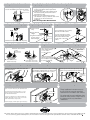
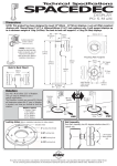
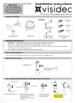
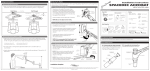
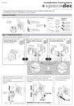
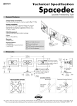
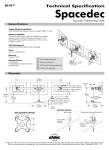
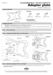
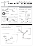
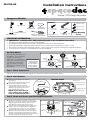
Installation Instructions
SD-POS-HA
Display l POS Height Adjustable
Component Checklist
Hardware
M4x10mm (x4)
Top Cap (x1)
VESA Plate (x1)
M4x12mm (x4)
Installation
Template (x1)
3/2.5mm
Allen Key (x1 each)
14 Gauge
Screws (x4)
M4x16mm (x4)
Screw Cover (x1)
POS Assembly (x1)
M5 Grub Screw (x1)
NOTE: Philips-head
screwdriver not supplied
Display Mounting
Screws
Security Screw (x1)
(optional)
IMPORTANT INFORMATION:
!
!
!
!
!
!
IMPORTANT - Install Spacedec POS Height Adjustable as per Installation Instructions.
This product supports a maximum load of 20kg (44lbs).
This product supports VESA mounting hole configurations: 75x75mm and 100x100mm.
The height adjustment range (from desk level to the centre of the screen) 330-450mm (12.99"-17.72").
The minimum thickness of the mounting surface is 15mm (0.59") when using the manufacturer supplied Hardware.
The manufacturer accepts no responsibility for incorrect installation.
Mounting Options
OR
Your SD-POS-HA offers 355°
of Rotation. This can also be
limited to suit a specific
application. The direction in
Rotation Options
which you mount SD-POS-HA 0° Rotation (Fixed)
will determine where the 5°
0-90° Rotation
0-180° Rotation
gap in rotation is located,
0-270° Rotation
and how you choose to limit
0-355° Rotation
the rotation.
5 Gap
in Rotation
Direction
Arrow
90
180
270
5 Gap in
Rotation
0
0
355
355
90
USER
Direction Arrow
270
180
USER
Step 1. Check Components
Check you have received all parts against the component checklist and Hardware above.
Step 2. Limit Rotation
A. Determine the degree of rotation
you require
(refer to Mounting Options above).
B. To limit the rotation, use the
2.5mm Allen Key to insert the
supplied M5 Grub Screw into your
chosen Locking Hole until it sits
flush with the Base Plate.
NOTE: If you want the full
355° rotation, you do NOT
need to install a grub screw.
LOCKING HOLES
Direction Arrow
0 Locking Hole (Fixed)
2.5mm Allen Key
0-90 Locking Hole
M5 Grub Screw
Base Plate
0-180 Locking Hole
0-270 Locking Hole
Step 3. Locate and Secure your POS Height Adjustable
A. Position the Installation Template in the desired
location on your work surface. Ensure the straight
edge sits perpendicular with the User’s line of
sight. Mark the center points of each of the
required holes onto the work surface with a pencil.
B. Drill 4 x 3mm (0.12") Pilot Holes to a depth of
15mm (0.59"). Use a 45mm (1.75") hole saw to
drill the Cable Access Hole in the work surface.
C. Reposition SD-POS-HA with the “Direction Arrow”
pointing in the direction required for your chosen
rotation. Secure the SD-POS-HA to the work surface
using the supplied 14 Gauge Screws (x4).
4x
14 Gauge
Screws (x4)
3mm (0.12")
Pilot Holes
Centre for 45mm (1.75")
Cable Access Hole
INSTALLATION
TEMPLATE
4x
3mm (0.12")
Pilot Holes
45mm
(1.75") Cable
Access Hole
USER
Step 5. (Optional) Install Monitor Security Cable
Step 4. Attach Screw Cover
Remove the paper backing from the Screw
Cover and adhere to the base as shown.
A. Loop the Security Cable (Kensington or
similar) around the internal post of the
POS Assembly.
B. Feed the other end of the cable through
the POS Assembly and out the Cable
Management Hole.
C. After you have attached the monitor
(As directed in Step 9) install the lock to the
monitor as per the manufacturer
guidelines.
Note: Security Cable Not Included
Screw Cover
Step 6. Install Top Cap
Top Cap
PUSH
Step 7. Adjust Pole Height
Step 8. Install Monitor Cables
A. Loosen Hand
Grip.
Option 1:
B. Set to desired
Height
ADJUST
HEIGHT
TIGHTEN
TO LOCK
C. Tighten Hand Grip
to lock pole at
desired height.
Prior to attaching your monitor,
install the monitor cables.
LOOSEN
Hand Grip
IN
Run them through the Front
Cable Access Port, down the
pole and out of the Cable
Access Hole in the work
surface.
OUT
Push down firmly to attach the Top Cap.
Step 9. Attach the VESA Plate to your Display
Step 8. Install Monitor Cables
Option 2: When you do not want to route the cables
below the work surface.
CABLE
ACCESS CAP
OUT
Mounting Screws (x4)
VESA Plate
There are two mounting
hole configurations:
• 75 x 75mm
• 100 x 100mm
PUSH
A. Push out to remove
Cable Access Cap
B. Pull cables out through
Rear Cable Access Port.
Choose appropriate
Mounting Screws from
the Hardware supplied
to suit your Display.
75mm
100mm
75mm
100mm
Top of
Display
Back of Display
Step 10. Attach your Display to the POS Assembly
Hook the top of the VESA plate onto the
Quickshift Mount.
HOOK
Press and hold the Release Buttons. Gently
push bottom of VESA Plate into Quickshift
Mount. Release Buttons to lock in place.
(optional) Insert the Security Screw, and
tighten using a Phillips-head Screwdriver
TIGHTEN
PUSH
Back of Display
Release Button
Security Screw
Back of Display
Position your Display to the desired viewing angle using the 40°
angular movement allowed by the VESA Ball Mount.
To make any adjustments, use the 3mm Allen Key
supplied. Apply half a turn at a time to each screw
on the Tension Plate to adjust evenly.
Check the display, and the adjust again if necessary.
Tension Plate
TIGHTEN (+kg)
LOOSEN (-kg)
Back of Display
Advanced Security Installation
Step 11. Adjust the VESA Ball Mount
If the display does not hold its position, or is too
resistant, adjust the Tension Plate located at the
rear of the VESA Ball Mount.
Phillips-head
Screwdriver
3mm Allen Key
These Installation Instructions secure
the SD-POS-HA using the provided
fasteners from the above work surface.
For advanced Security Installation from
below the work surface. Please refer to
the Advanced Security Installation
Addendum.
Installation Complete
No portion of this document or any artwork contained herein should be reproduced in anyway without the express written consent Atdec Pty Ltd.
Due to continuing product development, the manufacturer reserves the right to alter specifications without notice. Published 08.02.12 C