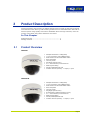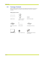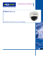
1
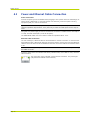
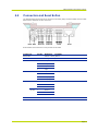
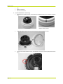
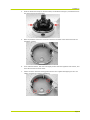
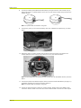
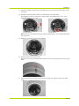
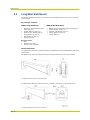
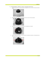
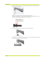
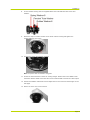
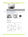
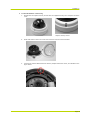
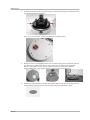
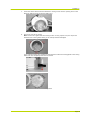
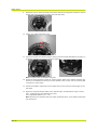
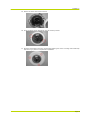
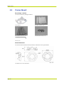
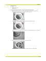
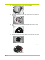
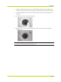
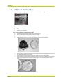
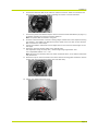
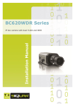
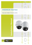
Installation Manual FD820 Series High-Definition Fixed-Dome Camera with Day/Night Note: To ensure proper operation, please read this manual thoroughly before using the product and retain the information for future reference. Copyright © 2012 Siqura B.V. All rights reserved. FD820 1.0 Installation Manual v1 (122003-1) AIT5.2-MW07SP2 Nothing from this publication may be copied, translated, reproduced, and/or published by means of printing, photocopying, or by any other means without the prior written permission of Siqura. Siqura reserves the right to modify specifications stated in this manual. Brand names Any brand names mentioned in this manual are registered trademarks of their respective owners. Liability Siqura accepts no liability for claims from third parties arising from improper use other than that stated in this manual. Although considerable care has been taken to ensure a correct and suitably comprehensive description of all relevant components, the manual may nonetheless contain errors and inaccuracies. Should you detect any errors or inaccuracies in the manual, we would be grateful if you would inform us. This helps us to further improve our documentation. More information If you have any comments or queries concerning any aspect related to the product, please do not hesitate to contact: The Netherlands USA Corporate Headquarters Siqura B.V. Zuidelijk Halfrond 4 2801 DD Gouda, The Netherlands US Corporate Offices TKH Security Solutions USA, Inc. 12920 Cloverleaf Center Drive Germantown, Maryland 20874, USA General Fax E-mail WWW General Fax E-mail WWW : +31 182 592 333 : +31 182 592 123 : [email protected] : www.siqura.com : +1 301 444 2200 : +1 301 444 2299 : [email protected] : www.tkhsecurity-usa.com Contents 1 INTRODUCTION 3 2 SAFETY INFORMATION 5 2.1 2.2 3 PRODUCT DESCRIPTION 3.1 3.2 4 PRODUCT OVERVIEW PACKAGE CONTENTS CABLE DEFINITION AND REQUIREMENTS 4.1 4.2 4.3 4.4 5 CAUTIONS REGULATIONS INTERFACE REQUIREMENTS SYSTEM COMPATIBILITY POWER AND ETHERNET CABLE CONNECTION CONNECTORS AND RESET BUTTON INSTALLATION 5.1 5.2 5.3 5.4 5.5 5.6 CAMERA DIMENSIONS SURFACE MOUNT LONG/MINI WALL MOUNT RECESSED CEILING MOUNT CORNER MOUNT 4S MOUNT ELECTRICAL BOX APPENDIX: TECHNICAL SPECIFICATIONS 5 6 7 7 8 9 9 9 10 11 13 13 13 18 22 28 32 35 Page i C 1 h a p t e r 1 Introduction Document scope This manual applies to Siqura's high-definition (HD) vandal-proof fixed-dome FD820 series cameras. It describes how to install and connect the FD820 camera. Operation and configuration of the FD820 camera is covered in the user manual. Intended audience This manual is aimed at installers and technicians involved in the installation of network devices, such as the FD820. Assumed skills and know-how To work with the FD820 camera, an installer or technician must have adequate knowledge and skills in the fields of: CCTV systems and components Electrical wiring and low-voltage electrical connections Ethernet network technologies and Internet Protocol (IP) Windows environments Web browsers Video, audio, data, and contact closure transmissions Video compression methods Specifications The information given in this manual was current when published. Siqura reserves the right to revise and improve its products. All specifications are subject to change without notice. Important Information Before proceeding, please read and observe all instructions and warnings in this manual. Retain this manual with the original bill of sale for future reference and, if necessary, warranty service. When unpacking your product, check for missing or damaged items. If any item is missing, or if damage is evident, do not install or operate this product. Contact your supplier for assistance. Page 3 FD820 Series Typographical conventions Before you start using this guide, it is important to understand the typographical conventions used in the documentation. The following kinds of formatting in the text identify special information. Page 4 Formatting convention Type of Information Numbered list Step-by-step procedures. You can follow these instructions to complete a specific task. Special Bold Items you must select, such as menu options, command buttons, or items in a list. Emphasis Used to emphasize the importance of a point or for variable expressions such as parameters. CAPITALS Names of keys on the keyboard. for example, SHIFT, CTRL, or ALT. KEY+KEY Key combinations for which the user must press and hold down one key and then press another, for example, CTRL+P, or ALT+F4. C 2 h a p t e r 2 Safety Information This chapter provides cautions on what to do and what not to do when working with or handling your FD820 unit. It also offers information on product compliance with environmental regulations and explains how to dispose of the product at the end of its service life. In This Chapter Cautions ........................................................................... 5 Regulations ....................................................................... 6 2.1 Cautions Handle the camera carefully. Do not abuse the camera. Avoid striking, shaking, etc. as the camera can be damaged by improper handling or storage. Do not disassemble the camera. To prevent electric shock, do not remove screws or covers. There are no user serviceable parts inside. Please consult technical support if a camera is suspected of malfunctioning. Do not operate the camera beyond the specified temperature, humidity, and power source ratings Verify that the power source is appropriate before you plug in and operate the unit. If the camera is installed outdoors, make sure it is sheltered from direct sunlight. Do not use strong or abrasive detergents when cleaning the camera. Use a dry cloth to clean the camera when it is dirty. If the dirt is hard to remove, use a mild detergent and wipe gently. To clean the lens, use lens tissue or a cotton tipped applicator and ethanol. DO NOT clean the lens with strong detergents. Ensure that camera installation is performed by a specialist. Only qualified service personnel or system installers should install and connect this product. Never face the camera towards the sun. Do not aim the camera at bright objects. Whether the camera is in use or not, never aim it at the sun or other extremely bright objects, as this can damage the camera. Page 5 FD820 Series 2.2 Regulations This device complies with Part 15 of the FCC Rules. Operation is subject to the following conditions. This device may not cause harmful interference. This device must accept any interference received, including interference that may cause undesired operation. This symbol on the product or on its packaging indicates that this product shall not be treated as household waste in accordance with Directive 2002/96/EC. Instead it shall be handed over to the applicable collection point for the recycling of electrical and electronic equipment. By proper waste handling of this product you ensure that it has no negative consequences for the environment and human health, which could otherwise be caused if this product is thrown into the garbage bin. The recycling of materials will help to conserve natural resources. For more information on how to recycle this product, please contact your local city office, your household waste disposal service or the seller of the product. Compliance is evidenced by written declaration from our suppliers, assuring that any potential trace contamination levels of restricted substances are below the maximum level set by EU Directive 2002/95/EC, or are exempted due to their application. Page 6 C 3 h a p t e r 3 Product Description Utilizing progressive scan sensors, the FD820 cameras produce images of rapid moving objects with minimum motion blurring. Dual streaming enables users to view MJPEG and H.264 video to achieve superior image quality and conserve bandwidth. With ultra-high resolution, users can monitor critical areas with greater detail than ever before. In This Chapter Product Overview ............................................................... 7 Package Contents .............................................................. 8 3.1 Product Overview FD820M1 Multiple Resolutions: 1080p/720p 1/2.7” Progressive scan CMOS Imager Dual stream of H.264 and MJPEG video Onvif compliant Two-way audio Day/Night (IR Cut-filter) 3.0 - 9mm Varifocal, motorized lens IP66 Ingress Rating 24VAC/12VDC/802.3af PoE Contact closures (alarms) - 1 output, 1 input Multiple Resolutions: 1080p/720p 1/2.7” Progressive scan CMOS Imager Dual stream of H.264 and MJPEG video Onvif compliant Two-way audio Day/Night (IR Cut-filter) IR Illuminator (effective distance: 25m) 3.0 - 9mm Varifocal, motorized lens IP66 Ingress Rating 24VAC/12VDC/802.3af PoE Contact closures (alarms) - 1 output, 1 input FD820M1IR Page 7 FD820 Series 3.2 Package Contents Before proceeding, please verify that the box contains the items listed here. If any item is missing or has defects, do not install or operate the product. Contact your supplier for assistance. FD820 package contents Page 8 FD820 camera 1.5A power adapter (indoor use only) Power terminal block Plastic screw anchors (x4) Security TORX Self-tapping screws (x4) Quick start guide Rubber washers (x6) CD (Device Search software and manuals) C 4 h a p t e r 4 Cable Definition and Requirements Read the instructions provided in this chapter thoroughly before installing the FD820 camera. In This Chapter Interface Requirements ...................................................... 9 System Compatibility.......................................................... 9 Power and Ethernet Cable Connection .................................. 10 Connectors and Reset Button .............................................. 11 4.1 Interface Requirements The FD820 camera can be accessed and configured from a standard web browser supporting ActiveX controls. The browsing PC must meet the system requirements described in the table below. Items Personal Computer 4.2 Minimum Requirements 1 Intel Pentium IV, 3 GHz or higher 2 Intel Core2 Duo, 2 GHz or higher 3 2 GB RAM or higher 4 AGP graphics card 64 MB RAM, Direct Draw Operating System Windows Vista or XP Web Browser Microsoft Internet Explorer 6.0 or later Network Card 10Base-T (10 Mbps) or 100Base-TX (100 Mbps) operation Viewer ActiveX control plug-in for Microsoft IE System Compatibility To ensure system compatibility, download the latest firmware from Support > Software on the Siqura web site at http://www.siqura.com/. Registration is required. Page 9 FD820 Series 4.3 Power and Ethernet Cable Connection Power Connection Connect the power jack to the FD820 before plugging it into a power socket to avoid danger of electric shock. Additionally, if using PoE (Power over Ethernet), make sure power sourcing equipment (PSE) is in use on the network. Important: If the camera is deployed in temperatures above -30°C, PoE may be used. If the camera's operation requirement is -40°C, then only a 12VDC or 24VAC power source may be used. Using PoE or a power supply, the fan is on whenever the heater is enabled. Power consumption is 5.5W; 12W with heater/fan (+3.6W for IR option). The FD820M1IR model must use 12VDC or 24VAc for operation below -10°C. Ethernet Cable Connection The use of Category 5 Ethernet cable is recommended for network connection. To have the best transmission quality, cable length shall not exceed 100 meters. Connect one end of the Ethernet cable to the RJ-45 connector of the FD820 and the other end of the cable to the network switch or PC. Note: In some cases, you may need to use an Ethernet crossover cable with directly connecting the FD820 to the PC. Check the status of the link indicator and activity indicator LEDs; if the LEDs are unlit, check the LAN connection. The green light (right) indicates a good network connection. The yellow light (left) flashes to indicate network activity. Page 10 Cable Definition and Requirements 4.4 Connectors and Reset Button The diagram below shows part of the printed circuit board (PCB) inside the FD820. See the table below for the definition of each connector. Reset button and connectors on the printed circuit board Connector Pin No. Definition Reset button - Restore to factory default BNC - Analog video output Alarm I/O 1 Output + 2 Output - 3 Input + 4 Input - 1 Input 2 GND 3 Output (R) 4 Output (L) 1 Power 2 Reserved 3 GND 1 Power-1 2 Earth GND 3 Power-2 - 10/100 Mbps Ethernet / PoE Audio I/O Power DC 12V AC 24V Remarks Alarm connection Two-way audio transmission Power connection Page 11 C 5 h a p t e r 5 Installation Thoroughly read the instructions provided in this chapter before installing the FD820 camera. Refer to the diagrams in the section entitled Camera Dimensions. This manual covers the physical installation of the camera. For network and camera settings, consult the Siqura CD/(I)FD820 - User Manual. In This Chapter Camera Dimensions ........................................................... 13 Surface Mount ................................................................... 13 Long/Mini Wall Mount ......................................................... 18 Recessed Ceiling Mount ...................................................... 22 Corner Mount .................................................................... 28 4S Mount Electrical Box ...................................................... 32 5.1 Camera Dimensions The FD820 dimensions are provided in millimeters in the figure below. The FD820 dimensions 5.2 Surface Mount The FD820 camera can be installed directly on a wall or ceiling. Please note that the wall or ceiling must have enough strength to support the camera. Items Needed FD820 camera Ethernet cable DC jack cable (supplied; only necessary if not using PoE) Self-tapping screws (supplied) Plastic screw anchors (supplied) Security Torx (supplied) Required Tools Page 13 FD820 Series Drill Philips screwdriver Flat-head screwdriver To install the FD820 on a hard ceiling 1. Release the two captive security screws with the supplied security Torx and open the dome cover. FD820 camera Page 14 Captive Security Screw 2. Press both sides of the inner cover and remove it from the camera module. 3. Unscrew the module-fastened screw, as indicated in the figure, with the phillips-head screw driver. Installation 4. Press the sides of the snap-on camera module, as indicated in the figure, and detach it from the dome camera’s housing/plate. 5. Mark the positions of the four screw holes found on the base of the dome camera at the installation location. 6. In the marked locations, drill each hole slightly smaller than the supplied screw anchors, and insert the anchors into these holes. 7. Fasten the dome camera’s housing/plate with the four supplied self-tapping screws. Use rubber grommets for outdoor installations. Page 15 FD820 Series 8. Thread the cables (power/Ethernet/audio/alarm) through either the side conduit entry or back conduit entry, as shown below. Use a coin to screw off the conduit entry block for the FD820 camera. Note: The power cable is omitted if using PoE. 9. Connect the ports (on the camera module) with their cables/wires respectively, as shown below. 10. Attach the snap-on camera module into the dome camera’s housing, and tighten the module-fastened screw with the screw driver to secure the camera module. Note: The terminal blocks should face the side conduit entry for the FD820 camera, as shown above. 11. Connect the power and network outputs. Refer to Connectors and Reset Button (on page 11) for details regarding the camera connector definition. Note: The power cable is omitted if using PoE. 12. Access the camera browser-viewer for viewing images. Please refer to the FD820's user manual for further details. Users can also use the camera’s BNC connector for video output. Page 16 Installation 13. Position the FD820's motorized lens and adjust the its zoom level and focal length via the web page. 14. Adjust the camera’s pan/tilt holder to a desired angle, as shown below. Pan adjustment range is nearly 360°; rotation angle range approaches to 270°. Tilt is adjustable between -10° ~ 90°. Pan adjustment Tilt adjustment Note: Adjust the lens carefully within the limits mentioned above, or the cables underneath may be harmed. 15. Return the inner cover to the camera module. 16. Replace the back of the dome cover. Align the arrow mark on the dome cover with the one on the housing as shown in the figure below. 17. Screw on the two Torx screws on the side of the dome cover tightly to fasten the dome cover. Page 17 FD820 Series 5.3 Long/Mini Wall Mount This chapter describes pendant-style mounting of the FD820 cameras with a mini or long wall mount bracket. Kit package Contents WMO7 Long Wall Mount M8x16 Hex Head Stainless Steel Screw (Qty:x1) Rubber Washer-8 (Qty:x1) Pendant Tube Washer (Qty:x1) Spring Washer-8 (Qty:x1) Plain Washer-8 (Qty:x4) Sponge (Qty:x2) WM01A Mini Wall Mount M8x16 Hex Head Stainless Steel Screw (Qty:x1) Rubber Washer-8 (Qty:x1) Pendant Tube Washer (Qty:x1) Spring Washer-8 (Qty:x1) Sponge (Qty:x1) Required Tools: Drill Phillips screw driver Security Torx (supplied) Mount dimensions The installation is the same for both the WM07 Long Wall Mount and the WM01A Mini Wall Mount shown below. The WM07 Long Wall Mount dimensions are provided in millimeters in the figures below. The FD820 standard pendant mount dimensions The WM01A Mini Wall Mount dimensions are provided in millimeters in the figures below. The FD820 compact pendant mount dimensions Page 18 Installation To install the FD820 on a hard wall or ceiling or a square mount electrical box 1. Unscrew the Security Torx Screws with the supplied Security Torx driver and open the dome cover. 2. Press both sides of the inner cover and remove it from the camera module. 3. Unscrew the module-fastened Torx Screw, as indicated in the figure. 4. Press the sides of the snap-on camera module, as indicated in the figure, and detach it from the dome camera’s housing. Page 19 FD820 Series 5. Fasten the pendant mount onto the wall securely Run the Ethernet cable through the wall mount as shown in the below. M8x30 Hex Head Machine Screw (for WM07 Long Wall Mount only): The WM07 Long Wall Mount is supplied with four M8x30 Hex Head Machine Screws for the convenience of installation by fastening the mount to the wall. Page 20 6. Thread the Ethernet cable through the entry of the camera’s housing. 7. Rotate the joint of the dome camera housing into the entry of the pendant mount, aligning the screw hole of the joint with that of the mount. Installation 8. Fix the camera housing with the supplied M8x16 hex head stainless steel screw and washers. 9. Attach the snap-on camera module to the dome camera housing and tighten the module-fastened Torx screw. 10. Connect the power and network outputs. Note: The power cable is omitted if using PoE. 11. Access the camera browser-viewer for viewing images. Please refer to the FD820's user manual for further details. Users can also use the camera’s BNC connector for video output. 12. Position the FD820's motorized lens and adjust the its zoom level and focal length via the web page. 13. Return the inner cover to the camera. Page 21 FD820 Series 14. Close the dome cover and tighten the security Torx screws. Note: In case the zoom level and focal length are different with the dome cover on, adjust the zoom level and focal length through the dome cover. 5.4 Recessed Ceiling Mount The FD820 camera can be installed directly on a wall or ceiling. Please note that the wall or ceiling must have enough strength to support the camera. In-ceiling mount package contents T-Bar mount Trim ring Ceiling sticker Required Tools Drill Philips screwdriver Security Torx (provided) Mount dimensions The Surface Mount dimensions are provided in millimeters in the figures below. The FD820 recessed ceiling mount dimensions Page 22 Installation To install the FD820 on a hard ceiling 1. Release the two captive security screws with the supplied security Torx and open the dome cover. FD820 camera Captive Security Screw 2. Press both sides of the inner cover and remove it from the camera module. 3. Unscrew the module-fastened screw with the phillips-head screw driver, as indicated in the figure below. Page 23 FD820 Series 4. Press the sides of the snap-on camera module, as indicated in the figure, and detach it from the dome camera’s housing/plate. Use a coin to screw off the conduit entry block for the FD820camera. 5. Attach the camera housing/plate’s base to the recessed ceiling mount’s top plate, aligning the camera’s rear cable entry with the entry hole on the in-ceiling mount’s top plate. Align the three captive screws with the mating screw holes on the dome camera’s housing/plate’s base. Then tighten the three captive screws as shown below. 6. Page 24 Position the supplied adhesive-backed ceiling sticker (Ø176 mm) onto the ceiling where the camera will be mounted, and cut the ceiling hole using the template as a guide. Installation 7. 8. Insert the dome camera with the attached in-ceiling mount into the opening and run the Ethernet cable through the desired cable entry. Secure the Unit to the ceiling Note: Do Not over-tighten the three fixing screws. If using a power tool, the slip clutch should be set to the lightest setting or the clamps could be damaged. The in-ceiling mount’s wing clamps will draw the dome camera’s housing/plate to the ceiling board until it is completely flush with the board. Bottom views of installed in-ceiling mount Page 25 FD820 Series 9. Attach the snap-on camera module to the dome camera’s housing/plate. Install the camera module with the terminal blocks facing the side cable entry. 10. Tighten the module-fastening screw. 11. Connect the power and network outputs. Refer to Connectors and Reset Button (on page 11) for details regarding the camera connector definition. Note: The power cable is omitted if using PoE. 12. Access the camera browser-viewer for viewing images. Refer to the chapter Accessing the Camera in the FD820 User Manual for further details. Users can also use the camera’s BNC connector for video output. 13. Position the FD820's motorized lens and adjust the its zoom level and focal length via the web page. 14. Adjust the camera’s pan/tilt holder to the desired angle. Pan adjustment range is nearly 360°; rotation angle range approaches to 270°. Tilt is adjustable between -10° ~ 90°. Note: Adjust the lens carefully within the limits mentioned above, or the cables underneath may be harmed. Page 26 Installation 15. Return the inner cover to the camera. 16. Close the dome cover and tighten the two security screws. 17. Align the three holes in the trim ring with the retaining nut on the in-ceiling mount and snap the trim ring in place to complete the installation. Page 27 FD820 Series 5.5 Corner Mount Kit package contents The Corner Mount Kit package contains: Corner Mount M4 Plastic Anchors (x 6) M4 Self-tapping Screws (x 6) M4 Mechanical Screws (x 4) Security Torx Mount dimensions The Corner Mount dimensions are provided in millimeters in the figures below. The FD820 corner mount dimensions Page 28 Installation Required Tools: Drill Phillips screw driver Security Torx To install the FD820 on a hard wall or ceiling or a square mount electrical box 1. Match the corner mount at the ceiling corner. Please note that the dome camera’s housing/plate installing holes are in position as the right figure. 2. Drill six holes on the wall and the ceiling to install six M4 plastic anchors. Fix the corner mount on the ceiling by fastening six M4 self-tapping screws in the plastic anchors. 3. Place the dome camera’s housing/plate in the corner mount. Note: The snap-on camera module is in the position shown in the image above. Page 29 FD820 Series 4. Thread the RJ-45 cable through the dome camera’s housing/plate. 5. Tighten the four M4 mechanical screws to install the dome camera’s housing/plate in the corner mount. 6. Place the camera module into the dome camera’s housing/plate until there is a “click” sound. 7. Tighten the screw on the camera module to fix the camera module on the dome camera’s housing/plate. 8. Connect the power and network outputs. Refer to Connectors and Reset Button (on page 11) for details regarding the camera connector definition. Note: The power cable is omitted if using PoE. Page 30 Installation 9. Access the camera browser-viewer for viewing images. Please refer to the FD820's user manual for further details. Users can also use the camera’s BNC connector for video output. 10. Position the FD820's motorized lens and adjust the its zoom level and focal length via the web page. 11. Install the inner cover on the camera module. 12. Place the dome cover back in position, tighten the two Torx screws with the supplied Security Torx. Note: In case the zoom level and focal length are different with the dome cover on, adjust the zoom level and focal length through the dome cover. Page 31 FD820 Series 5.6 4S Mount Electrical Box The indoor FD820 cameras can be installed in a 4S Mount Electrical Box. Required Tools To install the FD820 in a 4S Mount Electrical Box 1. Unscrew and open the dome cover with the Security Torx. 2. Run the wires (Ethernet and power) through the wall. Note: The Power Cable is omitted if using PoE. 3. Press both sides of the inner cover and remove it from the camera module. 4. Detach the snap-on camera module from the FD820 camera’s housing/plate by unscrewing the module-fastened Torx screw first. Press the sides of camera module and pull it slightly out of the housing/plate. Thread the power and/or Ethernet cables through either the side conduit entry or the back conduit entry and fasten the camera’s housing/plate to the electrical box with the two screws. 5. Page 32 Drill Philips screwdriver Security Torx (provided) Installation 6. Connect the Ethernet cable to the camera’s network connector. Refer to Connectors and Reset Button (on page 11) for details regarding the camera connector definition. 7. Connect the power and network outputs. Refer to Connectors and Reset Button (on page 11) for details regarding the camera connector definition. Note: The power cable is omitted if using PoE. 8. Access the camera browser-viewer for viewing images. Please refer to the chapter Accessing the Camera in the FD820 User Manual for further details. Users can also use the camera’s BNC connector for video output. 9. Position the FD820's motorized lens and adjust the its zoom level and focal length via the web page. 10. Adjust the camera’s pan/tilt holder to the desired angle. Pan adjustment range is nearly 360°; rotation angle range approaches 270°. Tilt is adjustable between -10° ~ 90°. Note: Adjust the lens carefully within the limits mentioned above, or the cables underneath may be harmed. 11. Attach the snap-on camera module to the dome camera’s housing/plate. Install the camera module with the terminal blocks facing the side cable entry. 12. Tighten the module-fastening screw. Page 33 FD820 Series 13. Replace the back of the dome cover. Align the arrow mark on the dome cover with the one on the housing as shown in the figure below. 14. Screw on the two Torx screws on the side of the dome cover tightly to fasten the dome cover. Page 34 C h a p t e r 6 Appendix: Technical Specifications Item Siqura FD820 CAMERA Image sensor 1/2.7 in. progressive scan 1080p CMOS Effective pixels 1920x1080 Minimum illumination 0.6 lux color, 0.2lux B/W @F1.2 Shutter speed 1~1/10000 s Signal-to-noise ratio >40 dB Lens 3.0 - 9.0mm, F1.2 Lens type DC auto iris, motorized zoom, focus Horizontal field of view 103.5°(W) ~ 34.3°(T) Analog output BNC (1.0 Vp-p) FUNCTIONS Brightness Manual Exposure Auto/Manual Sharpness Manual Contrast Manual AGC Auto White balance Auto/Manual Saturation Manual Hue Manual Rotation Flip, mirror, 90° and 180° rotate Backlight compensation On/Off Digital zoom Wide dynamic range On/Off Noise reduction 2D/3D Motion detection On/Off (10 zones) Privacy masks 5 On-screen text Date, Time, Title (20 characters) Local recording Continuous, Scheduled, Alarm Tampering alarm Blocked/moved image NETWORK Interface 10/100 Ethernet (RJ-45) Page 35 FD820 Series Item Siqura FD820 Protocols TCP/IP, UDP, RTP, RTSP, HTTP, ICMP, FTP, SMTP, DHCP, NTP, PPPoE, UPnP, IGMP, SNMP, 802.1x, HTTPS and IPv4/v6 Password levels User and administrator Supported browsers Internet Explorer (6.0+), Chrome, Firefox, Safari User accounts 20 Video Number of video streams 2x H.264 or H.264/MJPEG Frame rate 1 to 30 fps (NTSC) / 1 to 25 fps (PAL) Compression algorithms H.264 MP (ISO/IEC 14496-10); MJPEG Supported resolutions 1080p (1920x1080); 720p (1280x720); 1024x768; 800x600; D1 (720x480); CIF (352x240) TV System NTSC / PAL Maximum streaming capabilities Stream 1 Stream 2 H.264 - 1080p30 H.264- D1 30fps MJPEG- D1 30fps H.264 - 1080p15 H.264 - 1080p15 MJPEG- 1080p15 H.264 - 720p30 H.264 - 720p30 H.264 - 720p30 MJPEG- 720p30 MJPEG - 1080p30 None AUDIO Compression G.711, 8kHz, A-LAW, μ-Law, 64 kbit/s; G.726, 8kHz, 40 kbit/s STORAGE Storage Micro secure digital (SD) card, 32GB CONTACT CLOSURES Input 5V 10 kΩ pull-up Output Photocoupler transistor output Reactions 4-pin terminal block, pitch 3.5 mm POWERING Power consumption 5.5W, 12W with heater/fan (+3.6W for IR option) Power 12VDC/ 24VAC/ 802.3af Power-over-Ethernet Power connector 3-pin terminal block Power adapter (included) 110-230VAC to 12VDC, 1.5A 50/60Hz MECHANICAL Dimension Ø151.4 x 130 mm (Ø5.96 x 5.14 in.) Weight 1 kg (2.2 lbs) Color RAL-9003 Connectors RJ-45, BNC Built-in IR Illuminator (optional) Working distance Page 36 up to 25m Appendix: Technical Specifications Item Siqura FD820 Wavelength 850nm Number of LEDs 23 ENVIRONMENT Operating Temperature (12VDC/24VAC) -40°C to +50°C (-40°F to +122°F) Operating Temperature (PoE) -30°C to +50°C (-22°F to +122°F) Operating Temperature -IR model (PoE) -10°C to +50°C (14°F to +122°F) Relative Humidity 10-90% as long as there is no condensation Note: Weight and dimensions are approximate. All specifications are subject to change without notice. Page 37