1
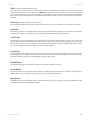
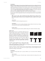
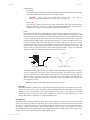
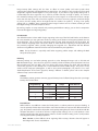
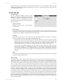
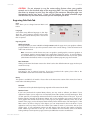
User Manual
User Guide
Advanced Laser System Operation
From the PPI and speed settings to Rubber Stamp and Image Enhancement settings, this section covers how each
feature of the Manual Control Printer Driver funtions for the advanced user.
Note: When adjusting the printer driver settings in the Manual Control Tab, it is highly recommended that you
practice engraving or cutting on a scrap portion of that material in case the settings need to be re-adjusted to
obtain the desired results.
Manual Control Printer Driver
The Manual Control Tab in the printer driver gives you full control
of the engraving and vector settings. This tab of the printer driver
is meant for the advanced user.
Color, Power, Speed, and PPI
To change the % Power, % Speed and/or PPI of a color, position
the mouse arrow on the color name and click once. This will
highlight the color’s parameters and will allow you to change
the settings by using the scroll bars, plus (+) or minus (-)
buttons or by typing in each setting in the appropriate
control box. It is possible to click on more than one color to
set them to the same setting at the same time.
% Power
Available settings are from 0 to 100%. This setting is directly related to how deep the engraving will be. The higher
the setting, the deeper it engraves, marks or cuts, and vice-versa.
% Speed
Available settings are from 0 to 100%. This setting determines the maximum rate of travel of the motion system.
Actual engraving time (throughput) is not only dependent on the % Speed setting, but is also dependent on
the size and the placement of the graphic in the engraving field. The motion system will accelerate/decelerate
as fast as it can up to the chosen speed. If the motion system cannot achieve the chosen speed based on the
size of the graphic or graphical placement in the field, it will automatically adjust its speed internally to the
maximum speed it can achieve. This is evident when you see the motion system automatically slow down while
cutting curves or circles as opposed to straight lines. Automatic proportional pulsing (see PPI) of the laser beam
will ensure that there is no difference in the depth of cut from straight lines to curves. We will discuss how to
optimize the throughput of the system later in this manual.
% Power and % Speed work together in determining how deep the engraving or cutting will be. Higher power and
slower speeds produce deeper results. Lower power and higher speeds produce shallower results.
Note: 100% raster speed is different than 100% vector speed. Due to the inertia of the X-Axis arm, movements
in the Y-direction, and also depending on which model you have, vector speeds will range from one-third
to one-half the maximum raster speed.
Link to Table of Contents
48
User Manual
User Guide
PPI
Available settings are 1 to 1000. The laser beam is always pulsing and never “on” continuously even though it
may appear that way. The PPI setting indicates how many laser pulses, per linear inch, the laser cartridge
will emit. The pulsing of the laser beam is electronically linked to the motion system. These pulses will always
fire, equally spaced, from one to the next, regardless of changes in speed.
In raster mode, dot positioning is determined by the driver based on image dark areas. The
print driver has the ability to place dots at any resolution up to 1000 PPI according to the
image composition. For solid filled areas (solid black for example) the machine places dots
at 1000 PPI because all pixels are completely filled with color. For halftones, the print driver
determines laser pulse location based on whether image pixels are black or white (and edge
threshold decisions). For grayscale, the print driver determines laser pulse location and
power based on image pixel color value (and edge threshold decisions).
In vector mode, laser pulsing follows the path of the outline of the object. Imagine the
laser system working like a sewing machine where the stitching always remains
consistent whether you sew fast, slow or around curves. The setting you use will be
application material dependent. Using less than 150 PPI may result in the pulses being
spread so far apart that they may or may not touch one another. Perforated paper has this
characteristic. Higher PPI settings may cause more of a melting or burning effect on the
edges whereas lower PPI settings may reduce the burning, melting or charring, but may result in a serrated
or perforated-looking edge. Increasing or decreasing the PPI setting does not affect engraving speed, only the
frequency of the pulses.
Mode (Drop Down Menu)
The driver uses the word “MODE” because the laser system works similarly to the operation of a pen plotter
output device. A pen plotter physically selects a colored pen that matches the same colored objects in your
graphic, called “color mapping,” and draws the graphic, on paper, in that color. The laser system, however, applies
a Mode, % Power, % Speed and PPI setting, to the individually colored objects in your graphic. Up to eight (8) sets
of user-adjustable parameters, which control laser beam delivery to your application material, can be “mapped” to
the respectively color filled or outlined objects in your graphic.
Note: Black and white, grayscale and color bitmaps are all mapped to the black color’s settings.
Selecting the appropriate color and clicking the drop down menu button toggles through the following laser beam
delivery modes for the each of the eight respective pen colors.
t
RAST/VECT (default) raster fills and vector marks or cuts proper outlines.
t
RAST rasters all fills AND outlines regardless of outline thickness.
t
VECT only vector marks or cuts proper outlines. It will skip all fills and will skip all outlines with line weights
thicker than a hairline.
t
SKIP ignores all fills and outlines.
Laser (Dual laser cartridge system only)
If your laser system comes equipped with more than one laser cartridge, you are given the choice of using either
both laser cartridges or a single laser cartridge (Top or Bottom.) If your laser system has one laser tube, select the
appropriate laser cartridge according to your laser system set-up.
Z-Axis
This control on the Printer Driver lets you offset the Z-Axis table from the current focal point. When the feature is
turned on and a height is set, the table lowers to the height entered and starts engraving. This feature can be used as
a Material Thickness focusing method.
Link to Table of Contents
49
User Guide
User Manual
Flow (Computer Controlled Air Assist only)
This feature will not appear if you do not have the Computer Controlled Air Assist option. If you do have Computer
Controlled Air Assist, but are not using it, you MUST leave the setting to OFF, otherwise your system will hesitate
up to 10 seconds after you press the start button on the machine. If you purchased the Computer Controlled Air
Assist option, please refer to the Accessories Guide for detailed instructions on how to use the printer driver controls
properly.
Flow Rate (Computer Controlled Air Assist only)
To control the Flow Rate of the Computer Controlled Air Assist accessory, select from the percentage rates available.
Set Button
After making % Power, % Speed, PPI and any other adjustments for the Pen parameters, you must click the SET button
to register the changes. The changes will not be saved until the OK or APPLY buttons are clicked.
Save Button
By clicking Save, the “Save Engraving Setup” dialog box will appear and will allow you to enter in a file name. All
settings will be stored in this file that has a “.LAS” extension. These files can be stored in any directory on your hard
drive and you can have as many setting files as your disk can hold. Verify that you have clicked the SET button before
you save any .LAS files to ensure you have properly saved your settings.
Load Button
To recall printer driver settings that have been previously saved, click on the “Load” button and choose the desired
.LAS settings file. The settings that are currently on screen will be replaced by the settings from the .LAS file. You may
abort this change by clicking Cancel; clicking OK will approve the change.
Default Button
The Default button will reset the driver settings to the original manufacturer values.
Cancel Button
The Cancel button closes the printer driver window and takes you back to the previous window. If the SET, OK or
APPLY buttons were not clicked, the changes will not be saved by the Printer Driver.
Apply Button
The APPLY button saves all changes made to the Manual Control Tab. These changes include any modifications made
to the Raster, Vector or Engraving Field sub-tabs.
Link to Table of Contents
50
User Manual
User Guide
Raster Sub-Tab
Print Special Effects
In this dropdown list, you can choose from four
different printing modes, Normal (default), Clip art,
3D and Rubber Stamp.
Clip Art
This control simulates laser printer output and
is very useful if using a drawing with many
colors, shades of gray or many outlines. It is
recommended to turn this control ON when
using DRAWN clip art because there may be
some underlying cutting lines hiding behind filled areas. Having this control ON gives a what-you-seeis-what-you-get output very similar to laser printer output. The entire drawing will be raster engraved,
including all outlines, and only the Black color setting is used. The driver automatically turns OFF its
color-mapping feature and all colors are engraved as different shades of gray, represented by a halftone
pattern. The type of halftone pattern is based upon the “Quality” setting of the driver the same way
grayscale bitmaps are interpreted. Since clip art images use a wide variety of colors, shades and outlines,
the only effective way to engrave these images is to have this control turned ON. Clip art mode also
provides greater compatibility with Windows software that does not work well with vector devices such
as the laser system. Do not activate this control when printing photographs or bitmapped images; use it
only with DRAWN clip art.
3D
There are two ways to use the 3D feature. The first method is used to produce an engraving that has a
contoured depth, giving it a three dimensional feel. It is used in combination with grayscale bitmaps
by automatically assigning laser power levels to the shades of gray of the bitmap without converting
the image to a halftone. These power settings are based on the setting you entered for the color black
in the printer driver. The darkest shades of gray (black) will be assigned the value of the setting for the
black color. The lightest shade of gray (white) will automatically be assigned a 0% power. All other
shades of gray that fall between black and white will automatically be assigned an appropriate power
level that matches the darkness of the color. The engraving will appear “3D” because the depth of the
engraving will vary according to the image. Sometimes it takes several passes to create enough relief in the
engraving to get the desired results.
Special 3D software is required to produce the type of grayscale images that are compatible with
this mode. You cannot simply use ANY grayscale bitmap to produce a “3D” effect. Please contact our
Applications Department for the latest 3D software recommendations.
The second way to use the 3D feature is to engrave any photograph lightly onto the surface of hard
materials, such as black marble, anodized aluminum, painted brass, micro-surface engravers plastic, etc.,
to produce exceptional photographic quality. Using the appropriate materials and settings, the end
result is an engraving that looks more like a photograph than a halftoned or diffusion dithered image
does. To use the 3D feature in this method you must first follow the steps below.
Choose Your Material
The best material to use is one that has the highest contrast, such as black anodized aluminum, black
marble or black cored engravers plastic with a white micro surfaced coating. While other materials
may work okay, they may not produce the highest quality.
Establishing Nominal Power
Choose your % Speed and your Image Density settings. Set the PPI to 1000, but don’t set the %
Power setting just yet. The objective is to use the LOWEST % Power setting that produces the
most contrast such as the whitest (as in black anodized aluminum) or the darkest (as in black cored
engravers plastic with a white micro surfaced coating) results.
Link to Table of Contents
51
User Manual
User Guide
This is what we call the “nominal” power setting. Over-powering the material will produce poor
results.
In your graphics software, create a series of five rectangles that are about ¼ inch high and 6 inches
wide as in the following diagram:
Starting with the top rectangle, set the power setting to a value that you know will be too low. For
example, engrave the first rectangle at 5% power, increasing the power for each subsequent
rectangle in 5% increments, finishing the series off at 25% power and note the results. Choose the
rectangle that uses the lowest % Power setting to achieve the most contrast. If 25% is not enough
power, then engrave the rectangles once again, this time starting at 25% and increasing in 5%
increments as above.
In this particular example, we’ll say that 20% power looks over-burned, but 15% appears
under-burned. Since the material may be sensitive to small power changes, you may need to
narrow it down a bit further. Engrave a new series of rectangles, but this time start the top rectangle
at 15% then add 1% for the next rectangle, and so forth, until you find the best setting between 15%
and 20%.
The setting that produces the highest contrast using the least amount of % Power is called the
“nominal power setting.”
Engraving a Calibration Scale
Now that you have established the nominal power setting, you will need to engrave a grayscale
calibration scale. You can create one of your own or use the one provided for you which can be
found on the Software Installation CD-ROM called “3D Calibration Scale.cdr.” This is a CorelDRAW 8
file so using versions 8 and higher will open the file.
The scale looks like this:
Each rectangle is 0.5 inches wide (12.7 mm) and 0.25 inches tall (6.35 mm). Each successive shade
of gray is incremental by 16 levels starting at 0 and ending at 255. The numbers below the scale
are there as a reference to the 16 levels of power control (explained later) and do not need to be
engraved if you do not want to.
Engrave the calibration scale, onto your material, using the nominal power setting you established
earlier. Compare it to the actual calibration scale that you see on screen or in this manual. If the
response of your material to the laser beam was perfectly linear, then the result should look exactly
like the calibration scale. Most likely you will find that several rectangles appear to have the same
appearance of shading. The objective would be to engrave the calibration scale and produce a
result that would appear as if each rectangle would have its own distinguishable level of gray,
starting from white all the way to black. To help you achieve those results, the printer driver gives
you the ability to calibrate the power level of each one of the rectangles. To access the feature, click
on the “Setup” button.
Link to Table of Contents
52
User Manual
User Guide
Setup Button
When you click this button, the ULS 3D Power Calibration screen will appear. Notice that there are
16 slider bars representing the 16 shades of gray of the calibration scale. The 00 and the 15 are not
adjustable as they represent white and black. The other 14 can be adjusted. The objective is to go
back and forth between adjusting the corresponding slider bars and re-engraving the calibration
scale until you can duplicate the appearance of the calibration scale as best as possible. As you are
progressing, make sure you keep saving your settings in an LAS file just in case your computer
crashes, etc. This is a lengthy procedure so you do not want to have to do it twice.
Once you have duplicated the 3D Calibration Scale onto your material, calibration is now complete.
You only need to do this calibration one time for each material you intend on using to produce
photographs.
Note: If you are using a type of material that becomes lighter when you engrave, such as
black marble, you will need to invert the photograph first (make a negative image) in your
photo editing software, otherwise when you engrave the image, it will appear like a negative
image.
APPLY Button
Click Apply to enable the settings that you just set.
CLOSE Button
The Close button closes the 3D Power Calibration settings window and cancels any changes
you made to the scale if you didn’t click the APPLY button.
DEFAULTS Button
The Defaults button applies the factory default settings to the 3D Power Calibration settings.
Rubber Stamp
Rubber Stamp mode causes a “shouldering” effect when raster
engraving rubber stamp material or any other material that
requires a “shouldered” engraving. The effect looks as if the
laser beam engraved the material on an angle, but in
actuality it is the precise control of laser power that creates
this appearance. This is a “raster only” feature that only works
with black colored graphics and uses the power setting of
the black color in the printer driver. Vectors are processed
normally and can be used for vector engraving or cutting by
assigning any of the seven other printer driver colors to the
outline desired.
This image..
...turns into this
image by the driver...
...turns into this
...and the engraved
image looks like this.
...and the engraved
This image..
image by the driver...
image looks like this.
To obtain a “raised” engraving such as a rubber stamp, simply
create a “negative” graphic so that the background is black
and the text or graphic objects are white. This way, the background engraves and the text or objects
remain untouched, producing a “pyramid” effect.
To obtain a “chiseled” or “sunken” engraving, create a “positive” graphic so that the background is white
and the text or objects are black. This way, the text or graphic engraves and the background remains
untouched, producing a “chiseled” effect.
Setup Button
Selecting the Setup button opens a pop-up window so you can choose from the following
settings:
Taper Selection
Choose from various types of shoulder angles. Experiment with each setting and note the
result.
Link to Table of Contents
53
User Manual
User Guide
Image Options
Invert Page
This converts all black objects into white and all white objects into black for the entire page.
This is very useful for engraving a full sheet of rubber stamps.
CAUTION:
When using the “Invert Page” feature you
reduce your page size so that the entire work area is not engraved.
may
need
to
Mirror Page
This mirrors the entire page from left to right (horizontally). It will not mirror individual
objects or selections. This is very useful for engraving full sheets of rubber stamps because
the graphics on screen are non-mirrored and can be proof-read easily.
Power
Notice that when you click on different Taper Selections that the power table changes. This is
because the laser applies power in different profiles to produce different styles of taper. You
will notice that you cannot adjust the pre-defined Taper; however, if you would like to create
a custom taper of your own, first select the Taper Selection that you would like to start with
and then click the “NEW” button. This will copy the taper as a “Custom Shoulder” that you can
rename by typing a new name in the dialog box and clicking “Rename.” You can also adjust
the profile however you desire. Each slider bar controls the laser’s power for that step. The
numbers at the bottom of that slider bar define the width of the step in 0.001 inches (mils). The
square at the top of each slider bar is the activate/deactivate button. Always deactivate the
steps you are not using so that it will apply 100% power to that level.
0
8
20
31
39
49
59
100
Step Power %
Material
.002”
Step Width
Normal Rubber Stamp Setting
...will give you these results
The diagram on the previous page is an example of the Normal Rubber Stamp Taper Selection.
You can see that there are 8 steps used to create the shoulder. The surface of the material is
considered the first step and the bottom of the engraving is considered the last step. You can
define as many as 16 steps, but the first or the last steps are not definable because they are
fixed at a power setting of 0% and 100% respectively. You can only define the parameters for
the 14 steps in between.
Note: The maximum shoulder width is 0.056 inches (1.42 mm).
Reduction
Raster Block Reduction (also known as Print Growth Management) reduces the number of pixels of a
raster image only in the X and Y directions. Raster Block Reduction does not affect vector images.
Sliding the bar to the right will remove pixels from the image that is being engraved, practically
thinning the raster image. This feature does not affect your original file, only the file that is in cache
storage. This feature is useful for bar code labels with thin lines.
Image Density
The Image Density setting determines how many raster strokes per vertical inch of travel the motion
system steps down to produce the engraving. It can also be referred to as the vertical lines per inch or fill
spacing. In the Windows XP driver it is termed Image Density and there are six Image Density choices in
all models. Higher Image Density (DPI) settings produce better quality raster images, but reduce
productivity by increasing engraving time. Lower Image Density (DPI) settings produce lower quality raster
images, but increase productivity by decreasing engraving time.
Link to Table of Contents
54
User Manual
User Guide
Image Density (DPI) settings will also have an effect on vector quality and vector speeds when
vectoring lines other than straight horizontal or vertical lines. For example, a circle is made up of very small
straight-line segments linked together at very small angles. If you choose a high quality setting such as
6 (1000 DPI), then these segments are as small as possible and they are high in quality. The result is
the smoothest looking circle, but it will take longer to vector engrave or cut because the focus carriage
must start and stop at the ends of each line segment. Since there are many segments, it will take longer
to process, but the quality will be the highest that the machine can produce. If using a low quality
setting such as 1 (DRAFT), these segments become longer, but there are less of them, resulting in more
flat-edged looking curves that will process faster.
By running samples on scrap materials and practicing with different settings, you can find a compromise
between throughput and engraving quality.
Print Direction
The default direction is Down which begins engraving at the top of the field and finishes at the bottom.
On some materials you may get better results by starting at the bottom and engraving towards the top
of the field (Up). This is because the engraving smoke is being drawn towards the top of the field. On
some materials engraving Down causes the smoke or debris from the engraving to be deposited onto
the previously engraved surface, possibly damaging the engraved area. Experiment with the different
directions using different materials and choose the best method for your application.
Note: The Up direction is especially useful when engraving rubber stamps and utilizing the Back
Sweep Air Assist option.
Dithering
Dithering settings are used when printing grayscale or color bitmapped images such as TIF, JPG and
BMP formatted images. Since the laser system is essentially a black and white printer (black turns the laser
ON and white turns the laser OFF), and if you choose the correct settings, the driver will automatically
convert the grayscale or color bitmap into a 1-bit “halftoned” black and white image. This process is very
similar to how newspaper photographs, as well as laser printer photographs, are printed. For a more
detailedexplanation of the terms “grayscale,” “bitmap,” “halftone” or “dither,” please refer to the “Graphic
Software Setup” section in this manual.
Halftone
This halftone pattern generator converts grayscale bitmaps into a halftoned image based on your Image
Density choice in the driver.
Image Density
Angle
Shape
Lines Per Inch
6
45 Degrees
Round
180
5
45 Degrees
Round
90
4
45 Degrees
Round
60
3
45 Degrees
Round
45
2
45 Degrees
Round
36
Error Diffusion
Unlike halftone, error diffusion scatters the black pixels in a random pattern to represent shading. It
uses the quantity of black dots instead of the size of the black dots to represent the different shades of
gray. The pattern created will be dependent on the quality setting that you choose in the driver with the
exception that there is no chart to reference. Higher quality settings, such as 5, will produce a more
densely packed, higher dot quantity pattern, whereas a lower resolution setting, such as 2, will produce
a loosely packed, lower quantity dot pattern.
Note: Do not use Error Diffusion when engraving rubber stamps, otherwise dots will appear in
the background. Choose only Halftone.
Link to Table of Contents
55
User Manual
User Guide
Black and White Mode
The Black and White mode thresholds the image at 50% black. Each pixel that is greater than 50% black
will be converted into white and each pixel that is 50% black or less will be converted into black. This
effect is very similar to trying to duplicate a photograph using a photocopier.
Helpful Tip
Engraving grayscale bitmaps using a dithering pattern requires some practice and a bit of trial and
error to achieve perfection. It also requires some knowledge of bitmap editing software. These images
will visually appear different on one material as opposed to another material even if you use the same
driver settings. As a rule of thumb, use an Image Density setting of 5 using halftone or diffusion pattern
on harder materials, such as marble, anodized aluminum or microsurfaced engraver's plastic. Use an
Image Density setting of 3 using the halftone or diffusion pattern for softer materials, such as wood or
materials that you intend to engrave very deeply.
Image Enhancement
The Image Enhancements controls allow the user to “fine tune” the image to enable the laser system to
produce the highest quality, highest detailed images at high or low speeds. Image Enhancement may be
used at any engraving speed and with any material.
Note: Image Enhancement will cause files to take longer to print. Since most materials do not require
the use of Image Enhancement, use this feature only as needed. Image Enhancement and 3D Effects
cannot be selected at the same time. The printer driver will automatically notify you if you attempt
to do so. Image Enhancements work best for low power, high speed applications such as marking
anodized aluminum, etc.
The following procedure may appear lengthy, but when you learn how to use the controls, establishing
the correct parameters is easy and quick. Once you have established those parameters you can “SAVE”
them in the ULS printer driver as .LAS settings and recall them when needed. Many users choose to name
these saved settings according to the application material’s name.
Note: The Image Enhancement settings are designed to work with the BLACK pen color in the printer
driver. However, the other seven pen colors of the printer driver will use the same Image Enhancement
settings. Keep in mind that those settings will have a different resulting effect on if the other colors’ %
power, % speed and PPI are different than the black pen color’s setting.
Texturize
The Texturize feature adds random textured laser pulse patterns to an engraving job while using
Image Enhancements. It reduces motion system marks like banding from appearing on some materials
like tile and marble.
Definitions
CONTRAST: Contrast adjusts the difference between the unengraved and engraved areas in the high density
part of the graphic or where there is the most concentration of graphic pixels (in between the dotted lines),
as the following diagram illustrates:
Within this effective area, using too little CONTRAST may cause some parts of the letters to appear thin,
faint, fuzzy or even non-existent. Having too much CONTRAST will cause the effective area to appear thick,
bold or over-powered.
Link to Table of Contents
56
User Manual
User Guide
DEFINITION: Definition adjusts the difference between low density and the high density part of the
graphic. The low density parts of the graphic are typically the ascenders and descenders of text, single
pixels that may be horizontally spaced far from other pixels or the start of the graphic in the direction of
the raster stroke. Refer to the following diagram:
Setting this parameter too low may cause the effective part of the graphic to appear thin, faint, fuzzy or
non-existent. Too high of a parameter will cause these objects to appear thicker, bolder or more powered
than the high density areas of the graphic.
DENSITY: Density adjusts the difference between the entire unengraved and engraved areas. If the
parameter is too high, then the entire engraved image may appear thick, bold or over-powered. Too
low of a setting may cause the image to appear thin and pixels or parts of characters may disappear
altogether. The opposite effect would occur on inverted images such as white text on a black background.
TUNING: Tuning adjusts the image so that the pixels vertically line up with each other during the left
and right bidirectional raster strokes. A misadjusted TUNING value will cause the image to appear doubleimaged or inadvertently bolder than normal. A typical non-Image Enhanced TUNING value can be from -4
up to 0, whereas a typical Image Enhanced TUNING value generally averages around +4. TUNING will be
different if you have Image Enhancements enabled or disabled. Saving the printer driver settings will also
save the TUNING value.
Procedure
The following procedure assumes that you have some experience working with the laser system and have
a general idea of the Power, Speed, PPI and Image Density settings that you intend to use for the chosen
application material.
In the following example, we will be engraving painted brass choosing 100% speed for good throughput,
and Image Density 5 for good quality.
Step 1: Establish the nominal power setting.
In your graphics software, create a series of five rectangles that are about ¼ inch high (6.35 mm) and 6 inches
wide (152.4 mm) as in the following diagram:
Starting with the top rectangle, set the power setting to a value that you know will be too low. For example,
set it to 5% power and the rest of the parameters to 100% speed, 1000 PPI and Image Density 5. At this
time, ensure that Image Enhancement is NOT enabled. Engrave the first rectangle at 5% power,
increasing the power for each subsequent rectangle in increments of 5%, finishing the series off at 25%
power and note the results. Look for the LOWEST power setting that has the cleanest removal of material.
This would be the nominal power setting. While higher than nominal settings may also produce clean
engraving, it will overpower the material and may cause highly detailed engraving, unlike these rectangles,
to appear too thick, bold or washed-out. If 25% is not enough power, then engrave the rectangles again,
this time starting at 25% and increasing in 5% increments and so on. In our particular example, let’s say
that 20% power looks good, but 15% appears underpowered. Since we know that this material
happens to be sensitive to small power changes, we’ll need to narrow it down a bit further. Engrave the
rectangles once again, but this time start the top rectangle at 15% then add 1% for the next rectangle
and so on until you reach 20%. The results now indicate that the nominal power setting of 17% power
looks as if it is the LOWEST power setting that produces the cleanest results at 100% Speed, 1000 PPI
and Image Density 5.
Link to Table of Contents
57
User Manual
User Guide
Step 2: Using text to set the CONTRAST parameter.
Type in a random line of text, using the Times New Roman font, set at 8 or 10 points in size. Make sure
that the text string is at least 6 inches long and that the string includes punctuation marks, spaces and
lower and upper case letters as in the following example:
Universal Laser Systems, Inc. produces the “BEST” laser systems in the world!
Engrave the sample text with the settings determined in step 1, but this time ENABLE Image
Enhancement and set CONTRAST to 0, DEFINITION to 0, DENSITY to 100 and the TUNING value to +4. You
should expect the results to appear fuzzy, some of the characters will be missing and overall engraving
quality will not be as good as expected. This is normal. Move the line of text slightly downward in your
graphics software so that you will engrave a clean part of the material, but keep it close enough to the
previous engraving so that you have something to compare it to. Keep engraving samples and
adjusting the CONTRAST upward in increments of 5 and note the results. The objective is to adjust the
CONTRAST just enough to cause the high density areas of the text to be sharp and clear. Ignore the
appearance of the ascenders (like quotation marks or the tops of h’s) and descenders (like commas or
the bottom of lower case p’s) as they will appear faint and unclear. This is to be expected. DO NOT
adjust the CONTRAST setting to try to force these to appear; use the DEFINITION adjustment for those
characters. Right now, ONLY concentrate on the high density part of the characters. Setting CONTRAST
too high can cause the characters to appear “fat” or “bold.” Adjusting the CONTRAST by just one number
can make a big difference in appearance, so continue adjusting the setting by first increasing by 5 points
until you get close, but then fine tune the setting by increasing or decreasing by 1 point until the exact
setting is achieved.
Step 3: Adjusting DEFINITION to enhance the ascenders and descenders.
Now, increase the DEFINITION in increments of 5 at a time until the ascenders, descenders, commas,
quotation marks and any other low density area characters begin to appear. The objective is to increase
the setting just enough to cause these parts of the graphic to match the appearance of the high density
areas. Setting the DEFINITION too high will result in ascenders and descenders appearing too “fat” or “bold”
compared to the rest of the graphic.
Step 4: Reducing DENSITY as needed.
Once CONTRAST and DEFINITION have been set to the appropriate levels, the graphic may or may not
appear to be “fat” or “bold.” In most cases, the appearance will look great without making any more
adjustments. However, if everything appears overpowered or bold, try reducing the DENSITY down from
100 in increments of 5 and note the results. If the characters begin appear to be “chunky” or appear as if
pixels have been eliminated, then you have reduced it too much. Normally you can leave the DENSITY at
100. However, there may be cases where you need to reduce it. Reducing DENSITY can be very useful when
the image is inverted, such as white text with a black background. In this case, if the engraved area (the
background) is overpowering the text (foreground), then reducing the DENSITY may help thicken the text.
Step 5: Fine tuning the raster strokes.
At this point, you are finished with Image Enhancements. Make sure that you save your settings, but your
graphic may need a little more “fine tuning.” The typical TUNING setting is +4 when Image Enhancement
is enabled. However, this may or may not be the best setting for your system. To check this setting, you
should perform this last test. Engrave the same text with all your Image Enhancement settings, but this
time set the TUNING value to 0. Then move the graphic down and engrave it again with TUNING setting
+1, then +2 and so on all the way to +8. Compare each one to the other and find the one that is the
sharpest and clearest. Go back and set the TUNING value to the appropriate number and SAVE your settings
once again.
The Image Enhancement settings for that material are now complete. If you feel that you can fine tune it a
little more, go back to step 2 and try again, but this time start with the current Image Enhancement
settings that you saved. It is not necessary to reset your nominal power setting and we recommend that
you leave it the same as the value you determined in step 1.
Setting the Image Enhancement parameters using this procedure will cause all of your graphics, whether
big or small, inverted or not, dense or highly detailed, to appear better than ever. We suggest that you run
Link to Table of Contents
58
User Manual
User Guide
this procedure for all your materials and save your parameters. This may sound like a big job, but the
additional productivity and engraving quality that your system is capable of producing is well worth the
small amount of time spent.
Vector Sub-Tab
Vector Optimizer
The four available selections apply to vector
output only and have no effect on raster images.
Regardless of which of the following selections
you choose, vectors are grouped by pen color
and will always output in the color order listed in
the printer driver.
Enhance and Sort
Enchance and Sort turns on both features
simultaneously.
Enhance Only
The printer driver collects all the vectors from the application software and reconstructs them (so
to speak) by removing start and stop points within the vector curves so that they run smoother with
less jitter. It has no effect on straight, horizontal or vertical lines.
Sort Only
The printer driver collects all the vectors from the application software, stores them in temporary
memory, sorts them and then outputs them in the following order:
t
All open path vectors are output first (not closed path vectors like circles and squares) beginning
with the end point of the vector path that is closest to the current position of the focus carriage.
All subsequent open vector paths are output using the same “nearest neighbor” starting point
method which eliminates the random “vector hopping” that causes longer processing times.
t
Closed paths will follow, beginning with the innermost closed path and ending with the
outermost closed path. This is particularly useful in an elevated cutting application to prevent the
outer piece from falling first. The beginning point of a closed path is automatically selected by
the printer driver by the “nearest neighbor” vector path that has the steepest angle in the Y-Axis
direction.
None
This selection turns off Vector Optimizer. Vectors will be ordered exactly as sent from the user’s graphics
program and ordered by pen color.
Vector Scaling
This feature allows you to calibrate vector cutting or vector engraving to your particular application. To
calibrate the system, as an example, draw a precise 5” x 5” (127 x 127 mm) square in your graphics software.
In the printer driver, set the laser power and speed setting to vector mark (do not cut through) this square
onto some scrap material. After marking, remove the material and with a precision measuring device,
such as a caliper, measure the square in both the horizontal (X) and vertical (Y) directions. Let’s say that the
measurement was 4.997”x (126.92 mm) and 4.996”y (126.89 mm). Use the formula (desired length/measured
length) and enter the result into the X-axis and Y-axis boxes respectively. In this example, the result would
be X-axis = 1.0006 to 1.0000 and Y-axis = 1.0008 to 1.0000. The printer driver will scale the images larger for
numbers greater than 1.0000 and will scale the image smaller for numbers less than 1.0000. After changing
the numbers, repeat the marking procedure and verify that the square is scaled correctly. We used a 5” by 5”
(127 x 127 mm) square just as an example, but you can use any size object that is smaller than the maximum
size of the engraving field. Using the Vector scaling feature with larger images produces more accurate results.
Keep in mind that this feature DOES NOT scale raster images so if you combine raster and vector images in one
file, the raster image may not align with your vectors. You will need to manually position your raster images
in their desired positions.
Link to Table of Contents
59
User Manual
User Guide
CAUTION: Do not attempt to use the vector-scaling feature when your graphic
extends out to the absolute edge of the engraving field. You may accidentally cause
the driver to attempt to print past the edge of the maximum allowable page size.
Unexpected results may occur. If you use this feature, the actual allowable page
size decreases by the same amount that you are attempting to offset.
Engraving Field Sub-Tab
Units
Units allows you to change between Metric and
Inches.
Language
Select from many different languages in this drop
down list. Some language changes will not take
effect until the printer control panel is closed and
then re-opened.
Engraving Field
Width and Height
The page size that you enter in Width and Height must match the page size in your graphics software
program EXACTLY and it is up to the operator to enter in the correct settings. Select the metric box if
metric units are desired.
Note: Incorrect use of this feature may cause no graphics, partial graphics, erroneous graphics or
a misaligned graphics output relative to the application material to occur. To avoid problems,
we recommend that you set the Width and Height to the maximum field size of your laser system
(click the Max Size button) and also set your graphics software programs page size to match.
Max Size Button
Clicking on the Max Size button restores the driver back to the default maximum page size that your
model can accept.
Dual Head (PLS Only)
Dual Head is also an optional accessory. If you have purchased this option, please refer to the
ACCESSORIES section of the manual for more information.
Rotary
This option is available for all models. Please refer to the Accessories section of this manual on how to
install and use the Rotary Fixture.
Diameter
The diameter of the cylindrical object being engraved will be entered in this field.
Rotation Factor
If you have purchased the optional Rotary fixture, you may need to calibrate your fixture if your
application requires you to engrave or cut completely around the cylinder precisely 360 degrees. Only
use this option if you completely understand and have used the Rotary Fixture in the past. If you are
familiar with the operation of the Rotary Fixture and in your application you create a vector line or
raster graphic that extends from the top of the page (in your graphic software) all the way to the
bottom of the page, you should expect that the Rotary Fixture would rotate a full 360 degrees. If the
fixture comes up short or long by a few degrees, you can compensate for this in the driver. If your
application comes up short, increase the number past 1.0000 as much as you need to and run your
sample again. If your application rotates past 360 degrees, then decrease the number of degrees
below 1.0000 to get the ends to line up. You can calculate the exact number (refer to the Vector
Scaling technique on the previous page), but it may be difficult to measure circumference.
Link to Table of Contents
60