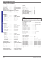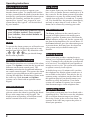
1
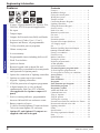
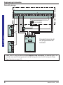
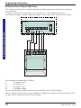
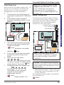
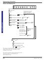
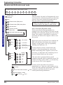
Intruder alarm system Engineering Information Power 0 Power 1 ZONE 1 ZONE 2 0 ZONE 3 ZONE 4 ZONE 5 ZONE 6 ZONE 7 ZONE 8 Tamper 1 2 3 2 3 4 5 6 7 8 1 Attack 5 Tamper Chime Day 2 3 4 6 7 8 9 Omit Reset Prog Set PA 4 5 6 7 8 9 Chime Omit Reset Prog Set PA Attack Day Accenta Power 8SP 401 Accenta G3 panel 8EP 395 Optima G3 panel with remote LED keypad and Communicator with built-in keypad and communicator 1 2 3 4 5 6 7 8 Power Attack Tamper Power Day ZONE 1 ZONE 2 0 ZONE 3 ZONE 4 ZONE 5 ZONE 6 ZONE 7 ZONE 8 Tamper 1 2 3 0 1 2 3 5 6 7 8 4 9 Chime Omit Reset Prog Set PA 4 5 6 7 8 9 Chime Omit Reset Prog Set PA Attack Day Power Accenta Accenta /! mini Accenta /! mini 8SP 400 Accenta mini G3 panel with remote LED keypad and communicator The above intruder systems are designed to comply with the installation requirements of BS 4737 1986/87. 4188-727 issue 2_10/02 8EP 396 Optima compact G3 panel with built-in keypad This manual provides information on Installation design, panel fixing, wiring, power up and programming of the intruder panels. 1 Engineering information Features Contents 8z RKP 4 MEM Features 8 6 REMOTE OUTPUT PART SET 5 09 SET ÿ 8 zones, all programmable for Security, Fire, 24H Fire, PTS or keyswitch applications ÿ ÿ ÿ ÿ PA input ÿ ÿ ÿ ÿ ÿ ÿ ÿ 3 fully selectable part set programs ÿ ÿ Option for connection of Lighting controllers ÿ ÿ NVM for protection of engineer programme ÿ Service warning indicator, programmable between 100 and 800 set and unset events ÿ Battery capacity of up to : 2.1Ah in Accenta/Optima G3 mini enclosure 7Ah in Accenta/Optima G3 enclosure ÿ Optima G3 and Optima G3 compact are supplied with built in keypad 2 Tamper input Outputs for External siren (Bell) and Strobe 4 Access level Codes, User 1, User 2, Engineer and Duress, all programmable Chime on any zone 8 event memory Programmable timers including bell cut off Walk Test facilities Quick set feature Remote keypad with on board PA and illuminated keys standard for Accenta panels and Optional for Optima panels Options to connect up to four remote keypads / Lighting controllers 6 digital outputs for a wire-in digital communicator, Red Care STU or dialler (Not applicable for Optima compact G3 panel) Features - - - - - - - - - - - - - Installation Design - - - - - - - - Fixing the control panel - - - - - Wiring the system - - - - - - - - Tamper network - - - - - - - - - Connecting Remote Keypads / Lighting controllers - - - - - - - Fitting the Remote Keypad - - - - Security zones - - - - - - - - - - Push to set zone - - - - - - - - - Remote keyswitch zone - - - - - Fire zone - - - - - - - - - - - - PA circuit - - - - - - - - - - - - Extension speaker - - - - - - - - External siren Output (Bell box) - 13V Supply output - - - - - - - - Set - - - - - - - - - - - - - - - Remote signalling Input and Outputs - - - - - 2 3 3 5 5 - - - - - 5 5 6 7 7 8 8 9 10 11 11 12 Factory set condition - First Power up - - - - Mains Connection - - Testing the system - - Engineer program mode - - - - - 14 15 15 16 16 System indications - - - - - - - - - - - - To enter Engineer program mode - - - - To Exit Engineer program mode - - - - - To reset panel to Factory set conditions - - Access Codes - - - - - - - - - - - - - - Zone Type - - - - - - - - - - - - - - - Zone Attributes - - - - - - - - - - - - - Programs - - - - - - - - - - - - - - - - Zone Function per Program - - - - - - Exit Modes program - - - - - - - - - - Programs 1,2 and 3 - - - - - - - - - - - Alarm and Walk tests - - - - - - - - - - Communicator tests - - - - - - - - - - - ‘Flag A’ Options - - - - - - - - - - - - - ‘Flag B’ options - - - - - - - - - - - - - Viewing the event log - - - - - - - - - - External siren (Bell box) and Service Timers Re-arm and Anticode reset code - - - - - Lighting controller - - - - - - - - - - - - Faults - - - - - - - - - - - - - - - - - - Specification- - - - - - - - - - - - - - - Servicing organisation Details - - - - - - Parts - - - - - - - - - - - - - - - - - - Quick Reference - - - - - - - - - - - - - - - 16 16 16 16 17 18 19 20 20 20 21 22 23 23 24 24 25 26 27 28 29 31 31 32 Filtering of Intruder alarms - - - - - - - - - - - 13 - - - - - - To exit operation - - - - - - - - - - - - - - - - 16 4188-727 issue 2_10/02 Accenta/Optima G3 intruder system Installation Design The purchase of this alarm system represents a major step forward in the protection of the property and its occupants. It is important to plan the installation before proceeding following the procedures and advice contained in this manual. detectors to ensure that this rating is not exceeded. Depending on which area you live, you may be required, by law to notify the Local Authority and Police of the new security Plan the position of each part of alarm installation. The the alarm system and the cable local authority requirements may differ from runs. Detectors should be sited area to area, therefore, it is advisable to contact with particular regard to the local environmental officer to obtain full details degree of coverage required of your area requirements. and the function of each of the zones. LA All of the system wiring is Fixing the control panel connected directly to the panel. The Accenta panel may be Caution: When positioning the control concealed inside a cupboard or panel ensure that it is located in a dry loft space, but it must be place away from damp areas. installed within the protected premises and in a position which is convenient The Accenta mini G3 enclosure is illustrated for a mains supply. The Optima panel may be here, however the procedures for the other installed near an entry/exit point. panels are similar. Power The Remote keypads (RKPs) should be mounted in positions a. which allows ease of operation for the system users, typically within the entry/exit route close to the final door and the master bedroom. ZONE 1 ZONE 2 0 ZONE 3 ZONE 4 ZONE 5 ZONE 6 ZONE 7 ZONE 8 Tamper 1 5 6 Chime Omit 2 3 4 7 8 9 Reset Prog Set PA Attack Day Power Accenta Additional internal sound speakers are recommended, these will provide high volume alarm tones and low volume entry/exit tones. Speakers should be positioned to provide good sound distribution throughout the building and so that the exit tone is audible outside the main entry / exit door. This will enable the system operator to check that the system is setting correctly. Finally note that the total current output of this control system (in alarm TOTAL condition) is 1A when supported by a fully charged battery. Calculate the total current consumption of every part of the system including the panel, remote keypads, external siren with strobe light (also called bell box) and I 4188-727 issue 2_10/02 Installation Design Accenta /! mini Remove the front cover(s) from the base assembly. Disconnect the transformer wires from the board, these are marked AC. Carefully remove the board by gently pushing down the holding clips on the bottom edge of the board and withdraw it from the base. 3 Engineering information Mounting holes Mounting holes Note: When replacing the board align it on the round support pillars to the bottom and allow it to click down past the clips at the top of the case. Refit the transformer wires into the terminal. FUSE T125mA 250V (ANTI-SURGE) Keypad and LEDs (except Power LED) are not fitted to Accenta G3 and Accenta mini G3 panels CONF SET ABORT INT PA FIRE 0V L/FAIL Communicator is not fitted to Optima compact G3 panel J3 RKP FUSE F2 LD1 LD2 LD3 LD4 LD5 LD6 LD7 LD8 LD9 J5 SOUND LD10 COMMS 1 2 3 4 5 6 7 8 9 CHIME OMIT RESET PROG SET LD22 +13V VR1 TAMP J1 SW1 J2 2 3 4 5 6 7 8 PA + TAMP +13V 0V - VOLUME J6 - + STROBE T A SCB D B BELL + - SET F5 1A F3 F1 BATTERY 0V 1 LD18 0 13V / SPEAKER c. BELL/STROBE b. 1A Danger High Voltage ~ 230V 50Hz 0.2A Board There are four fuses mounted on the circuit Fit the panel to the wall with suitable fixings. Ensure the wall surface is flat to board, all are 20mm quick blow. F1 1.6A - to protect the +ve line of 12V battery prevent base distortion. There are F2 1A - to protect the RKP 13V supply cable entry holes provided in the rear of the base and around the outside F3 1A - to protect the Speaker 13V supply edges through the thinned out plastic F5 1A - to protect the Siren (Bell) & Strobe sections which may be cut away as supply required. As supplied, wire links are fitted across the PA The hole provided adjacent to the and Tamper terminals to represent a closed mains transformer is a dedicated mains circuit. cable entry point. +13V Fixing the control panel Cable entry holes 1A 1.6A J4 + BATT AC Factory fitted links 4 4188-727 issue 2_10/02 Accenta/Optima G3 intruder system Caution: Always power-down the panel when wiring external circuits, to prevent damage to the panel electronics. Systematically wire and test each circuit: ÿ ÿ A combination of up to four remote keypads and lighting controller can be connected to the panel. Fitting the Remote Keypad d. Separate the RKP baseplate from the main assembly by slackening the retaining screw. e. Cut away the required thin wall sections around the edges of the baseplate for cable entry. f. The baseplate mounting holes are 60mm centres which allow it to be fixed to a single gang electrical metal box. As an alternative the baseplate may be fitted directly to the wall using the screws and wall plugs supplied, if these are not appropriate for the wall then use suitable alternative fixings. Zone, Tamper circuit and PA circuits Finish by wiring any additional extension speaker sounders, external siren (bell) / strobe and the 13V supply. Tamper network The Tamper circuit is used to protect all cables and detectors in the system from unauthorised access including the panel and RKP covers. The zone and PA tampers should be series wired and connected to the TAMP terminals. Terminals T & A are for the external siren Caution: The PCB board must not be tamper. The TAMP terminals at the bottom left of the board are for the RKP tampers. removed from the front moulding and Tamper alarms that occur in the Day mode doing so may invalidate the warranty. operate internal sounders only. Tamper alarms in g. Bring the cables into the baseplate and Set cause a full alarm condition. Tamper is wire to the terminal block on the indicated on the control panel and RKPs by the baseplate, see diagram on the next Tamper indicator. page. Connecting Remote Keypads / Lighting controllers h. Refit the RKP main assembly to the baseplate by hooking it onto the top holding clips. Check that the wiring does not foul the tamper switch/spring or the PCB support pillars. Resecure the screw in the bottom of the case. Note: Where an Accenta G3 or Accenta mini G3 panel is being installed ensure there is at least one remote keypad wired to the panel before first power up. Keypad Keypad TAMP SOUND COMMS 13V 0V TAMP SOUND Board COMMS 13V Board 0V GND 12V COMMS SOUND LD R OPTI-CAM Lighting Controller Board Panel Board 1A RKP FUSE F2 SOUND COMMS +13V 0V Maximum of up to 4 Remote Keypad / OPTI-CAM Lighting Controller combination allowed (See also the instructions supplied with the OPTI CAM lighting controller) 4188-727 issue 2_10/02 TAMP If only one Remote keypad is being used then connect TAMP back to the panel J5 5 Wiring the system Wiring the system Engineering information Security zones Panel Board J1 J2 1 2 3 4 5 6 7 8 PA + TAMP +13V 0V - Terminal block is not supplied PIR Security zones Door Contact + - Unused zones must be programmed as Unused. Alarm Door Contact Tamp PIR Note: The G3 range of panels are not supplied with wire links for unused zones. All unused zones must be programmed out by setting them to disabled using the Zone Type function see page 18. It is recommended that no more than 10 magnetic contacts are connected to the same zone. 6 4188-727 issue 2_10/02 Accenta/Optima G3 intruder system Push to set zone Any zone can be wired and configured as a Push to Set input. This can be a standard door bell push located outside the premises After starting the exit timer the building is vacated. As the switch is then momentaraily closed, a chime tone is produced and the system Sets. Sometimes referred to as ‘Terminate Set’ this facility is mandatory for communicating systems installed to NACOSS guidelines Panel Board J1 J2 1 3 2 5 4 6 PA + 8 7 TAMP +13V 0V - Note: The push to set switch can be connected to any zone. The zone must be programmed for PTS application. Remote keyswitch zone Any zone can be wired and programmed as a keyswitch input and used with a remote keyswitch or lock switch. For security reasons it is recommended that a tamper proof switch is used and that the switch wiring is not accessible from outside the premises. Panel Board J1 J2 1 2 3 4 5 6 7 8 PA + TAMP +13V 0V - Keyswitch Note: A keyswitch can be connected to any zone. The zone must be programmed for keyswitch application. The keyswitch may be used to Set (open contacts) or Unset (closed contacts) independently of RKPs. However in this situation the keyswitch may have to ‘catch up’ with the system. For example if the system is Set via an RKP and Unset with the keyswitch, it would have to be momentarily turned to its Set position then returned to its Unset position. The keyswitch will always Set program 1. It will also Unset the system or switch off an alarm activation. To Reset after an alarm and return to Day mode, the Reset key on the RKP will have to be pressed. 4188-727 issue 2_10/02 7 Push to set zone Press to Set Switch Engineering information Fire zone Any zone may be programmed as a fire zone. This will automatically exclude the availability of the zone from programs and normal security applications. Panel Board J1 J2 1 3 2 5 4 6 7 8 PA + TAMP +13V 0V - Fire detector Fire zone Note: Fire detector with relay base for output to intruder system. There are two types of fire zone, Standard and 24 hour type. The Standard fire zone detects fires only when the system is Set, where as the 24 hour fire zone detects fires all the time and will operate whether the system is Set or Unset. A fire will cause a distinctive internal sounder tone. The external sounders will pulse on and off at 2 second intervals and all RKP indicators will flash the affected zone. PA circuit Any quantity of normally closed type personal attack button may be wired in series and then connected to the PA circuit. Operational in Day and Set, the PA circuit will cause a full alarm condition when activated. PA is indicated on the control panel or RKP as Attack. Panel Board J1 J2 1 2 3 4 5 6 7 8 PA + TAMP +13V 0V - Panic Button Panic Button PA buttons may be fitted near the front door, or in a bedroom. 8 4188-727 issue 2_10/02 Accenta/Optima G3 intruder system Extension speaker Extension speaker may be connected to the loudspeaker terminals to produce high volume alarm tones and low volume entry / exit fault tones. Panel J6 + - STROBE T A SCB D B BELL + SET - BELL/STROBE VR1 F5 1A 13VSPEAKER Board VOLUME F3 1A Extension speaker 16 W Extension Speaker 16 W Extension Speaker Up to two 16 ohm extension speakers may be wired across the speaker terminals. Mounted in convenient positions within the installation the extension speakers will reproduce all of the alarm tones generated by the control panel. A control marked VOLUME in the centre of the board may be used to adjust the low volume entry/exit tones to suit environmental conditions. 4188-727 issue 2_10/02 9 Engineering information External siren Output (Bell box) The external siren (bell box) is usually installed in a high position from where the siren could be seen and heard. Terminal T A D B are for connection to the external siren. These terminals provide a power/hold-off supply, sounder trigger and tamper circuit to protect the external siren housing. Panel J6 + - External siren Output (Bell box) STROBE + STROBE T T A SCB E A D B BELL + - D B SET BELL/STROBE Board F5 1A Sonade The terminals are summarised as follows: T-Ve tamper return A-Ve supply (0V) D+Ve supply (12V) B-Ve Sounder trigger For ease of installation, ADE external sirens and modules use the same markings. Where a discrete external siren is used, it should be connected to terminals D & B. Terminals T & A are then used for tamper protection for the housing. 10 4188-727 issue 2_10/02 Accenta/Optima G3 intruder system Panel J6 + - STROBE T A SCB D B BELL + SET BELL/STROBE Board - F5 1A # Terminal block is not supplied # T E Sonade A D B + STROBE T E A D B 13V Supply output + STROBE Sonade Where self contained / powered sounders are used, carefully follow the manufacturers instructions, match each of the terminals to those above. 13V Supply output The 13V output is to power detectors which require a voltage supply (PIR detectors etc). The supply is present at all times and may be used to supply a total load of 350mA. Set The output , marked SET is used with latching detectors. The output becomes positive on correct Set of the system and is removed at the commencement of entry time or entry of the valid user code. 4188-727 issue 2_10/02 11 Engineering information Remote signalling Input and Outputs These outputs are not applicable to the Optima compact G3 panel. Remote signalling Input and Outputs These terminals have been provided for connection to remote signalling equipment such as a digital communicator, Red Care STU or speech dialler. Note: The operating polarity of the Communicator output terminals are programmable. L/FAIL This is a telephone line fail input which is held at approximately 6V by the panel circuitry. The input is activated when pulled to 0V by the telephone line fault output of the communicator. This is usually a voltage free relay or open collector transistor. When a telephone line fault occurs in the Day mode the panel provides an audible double beep every 10 minutes. This indication is automatically cleared when the fault is removed. A telephone line fault which occurs while the system is Set will not cause an alarm condition but any external siren (bell box) delay which is programmed will be cancelled and any intruder alarm which is triggered will operate instant sounders. 13V 0V These terminals provide a 13V supply for the communicator up to a total load of 200mA. The output is protected by a 250mA thermal fuse. If this fuse operates it may be reset by removing the load and allowing a few seconds for it to recover. Alternatively each output can be used to drive a relay(coil resistance > 1200 W ) connected between the output terminal and the 13V supply terminal. The relay will energise when the output port operates. It is recommended that a back EMF protection diode is used in parallel with the relay coil. L/FAIL +13V 0V FIRE PA ABORT CONF INT SET J3 Board Panel Communicator is not fitted to Optima compact G3 panel FIRE The fire output operates when the fire zone is triggered. PA The PA output operates when a PA alarm is triggered or a duress code is used. INT The intruder output is operated when an intruder condition is triggered whilst the system is set. SET The Set output operates whenever the system becomes set and is used to indicate opening and closing. ABORT Operates when an intruder alarm condition is switched off. CONF The confirmed alarm output operates when 2 independent zones are activated during the same alarm condition. OUTPUT PORT By default these outputs are programmed as active low output. They are held at 13V and fall to 0V when active, it can source or sink 10mA. The output polarity can be programmed. These outputs would normally be connected directly to the input channels of wire in type communicators and STUs. 12 4188-727 issue 2_10/02 Accenta/Optima G3 intruder system Important Notes a. Each output has been configured as active low and will normally require the EPROM or NVM for the communicator or STU to be programmed as active low or positive removed. However there may be differences between some pieces of equipment and some Alarm Receiving Centres (ARCs). Filtering of Intruder alarms b. Where the communicator is powered from an external source, not the panel and the outputs are being used without relays, the panel and external power supply will require a commoned negative supply rail. The exact method of filtering should be decided according to the regional Police Force Policy and ARC procedures. If the communicator is not fitted inside the panel and abort is being used, care should be taken to ensure that the abort connection cannot be damaged or severed as this could cause the ARC to incorrectly filter an alarm signal. Set/Unset A Set or Unset signal which is received by the ARC at around the same time as an intruder signal can be used to filter the alarm. d. It is very important that communicating systems are fully tested and that all signals are correctly received at the ARC when the system is installed and serviced. 4188-727 issue 2_10/02 In general, the panels offer the following methods which could be used to filter an alarm. Abort Output The abort output operates whenever a user code is entered or a keyswitch is used to switch off an intruder alarm condition. When an abort signal is received by ARC at or around the same time as an intruder signal, the alarm can be filtered. Restore of the Intruder Output The intruder alarm output is restored to 12V whenever a user code is entered or a keyswitch is used to switch off an intruder alarm condition. Where an intruder alarm is shortly followed by a restore at the ARC, this can be used to filter the alarm. 13 Remote signalling Input and Outputs c. A condition of most police Force Policies and under the guidance of NACOSS NACP 14 (Code of Practice for intruder Alarm Systems Signalling to Alarm Receiving Centres) is that all intruder alarm signals received by an Alarm Receiving Centre (ARC) must be filtered to establish their validity before passing to the police. Engineering information Factory set condition Factory set condition User code 1 - - - - - - - User code 2 - - - - - - - Duress Code - - - - - - - Engineer Code - - - - - - External siren Bell Duration External siren Bell Delay - - 0123 Not programmed Not programmed 9999 20 minutes No delay Program 1 Zone 1 - - Zone 2 - - Zones 3…8 Exit time- Entry - - Exit mode - - - - - - - Timed Time Inhibited Immediate 30seconds 30seconds timed Program 2 Zone1 - - Zone 2 - - Zone 3…8 Exit time- Entry time Exit mode - - - - - - - Timed Time inhibited Immediate 30seconds 30seconds Disabled Program 3 Zone 1 - Zone 2 - Zone3…8 Exit timeEntry time Exit mode - - - - - - Timed Time Inhibited Immediate 30seconds 30seconds Disabled Security Zones - - - Standard Fire zones 24 hour Fire zones - Push to set zones - - Keyswitch zones - - Double Knock zones Omit prevent zones- Zone debounce period - - - Zones 1…8 None programmed None programmed None programmed None programmed None programmed None programmed 300mS ALL zones 14 - Flag A Silent PA - - - - - - - RKP PA Enable - - - - Engineer Reset- - - - - Anti Code Reset - - - - Door bell on push to set Single key setting - - - Strobe on setting - - - - External siren Bell on Fire - No Yes No No No No No No Flag B Note: The entries marked # are not applicable for Optima compact G3 panel. #Communicator Output active high - - - - - #Line Fail active high - - - - - User Reset PA - - - User Reset Fire - - - #Program 1 to report #Program 2 to report #Program 3 to report Rearm counter - - - Service counter - - - Site Code - - - - - - Light Controller Light Threshold Light Hold Time Light Channel 1 Light Channel 2 Light Channel 3 Light Channel 4 Light Channel 5 Light Channel 6 Light Channel 7 Light Channel 8 - - - - - - - - No (active low) - - - - - - No (active low) No No Yes Yes Yes 3 (re-arms) Off 00 50% 30 seconds No zones assigned No zones assigned No zones assigned No zones assigned No zones assigned No zones assigned No zones assigned No zones assigned 4188-727 issue 2_10/02 Accenta/Optima G3 intruder system First Power up Note: The G3 range of panels are not supplied with wire links for unused zones. All unused zones must be programmed out by setting them to disabled using the Zone Type function see page 18. Before power up, for Optima compact only - fit the top cover on to the base and connect the speaker wires. Leave the cover in position throughout the reset of the installation. Panel Board BATTERY F1 Mains Connection The mains power should be connected using a 3 core cable of not less than 0.75mm sq. from a fused spur to the mains connector inside the control panel. The 2 A fused spur must be located close to the control panel. Dedicated mains supply from consumer unit. J4 1.6A + BATT 2A Fused Spur unit AC Panel N E L (red) + Black - 125mA Fuse 1.6A 12V battery c. e. AC 125mA Fuse and there is an audible 12V battery 9 Prog 9 9 9 Tamper indicator is lit. 4188-727 issue 2_10/02 Transformer Note: The mains supply must be connected by a technically competent person and according to current IEE regulations. Caution: To avoid the risk of electrical shock you must always totally isolate the mains supply before opening the control panel cover(s). system will go to Day mode . Immediately enter the engineer code Press . The system is now in Engineer program mode and can be programmed. Note the N E L Black - Alarm. indication. Fit the cover to hold down the tamper spring at the bottom centre of the board. Enter the user code, press 0 1 2 3 (factory set code). The alarm condition will cease and the Tamper + BATT (red) + Day f. J4 Transformer On connecting the battery the system will now go into alarm condition and Tamper is indicated Tamper d. Board F1 First Power up b. Check that the factory fitted links are connected to terminals PA, TAMP and T-A. Fit the battery wires to the BATT terminals on the Board, Red to + and Black to -. BATTERY a. ÿ Mains Input Fuse rating: 125mA, 250V type T (anti surge) and of a type approved to IEC 127 part 2 sheet III. On connecting the mains supply to the panel the power indicator is lit. Power 15 Engineering information Testing the system Complete the wiring of the system and then: ÿ Fully test the system and ensure it is fault free. ÿ ÿ Fully program the system ÿ Reset System indications Day Finally explain the operation of the system to the end user. The Operating Instructions are attached to the centre of this manual. Detach them and leave them with the user. Power The panel may be programmed to suit a wide variety of installations. Once the engineer program mode has been accessed, each configuration may be changed in any order. As each configuration is completed the system will automatically return to top level of engineer program mode. LED steady On indication LED flashing indication Internal sound Sound description NOTE: In general a flat beep is an indication of an incorrect key press. External devices Strobe External Siren - Unset system indication - Set system indication Note: The factory configured engineer’s access code is 9999. If however this code is changed then enter the appropriate code. Prog ZONE 1 - 8 Momentarily On 9 9 9 9 Acknowledge Tamper Day To Exit Engineer program mode Reset Day LED Off o/p ARC Output to Alarm Receiving Centre Communicator outputs are not applicable for Optima compact G3 panel Power To enter Engineer program mode Before entering engineer program mode the system should be in the Day mode, with the Day and Power indicators lit. Key 16 Quit the current function Leave program menu Down one menu level Fill in the installation log at the back of the manual and retain if for future reference. Engineer program mode Testing the system To exit operation To reset panel to Factory set conditions Caution: All configurations of the panel are restored to factory ‘default’ conditions. Within 5 seconds of powering up the panel Reset Reset reset beeps 4188-727 issue 2_10/02 Accenta/Optima G3 intruder system There are four codes used in the system, all are 4 digit and can be set to any number from 0000 to 9999. The access codes ensure that only authorised users can operate the system. User 1 and 2 codes The user 1 and user 2 codes have the same operation for testing, Setting and Unsetting, but user 1 code which is usually considered to be the Managers code has the authority to add, change or delete the user 2 code and duress code. Duress code Should be used in a hold up situation where there is pressure to Set or Unset the system. Entry of the code will allow the system to work normally but also generate a silent PA type alarm by operating the PA communicator output. The duress code is not applicable for Optima compact G3 system. Engineer code Accesses the Engineer Program mode to allow the system to be programmed. The engineer code will not set or unset the system. If configured the Engineers access code can be used to reset the system after an alarm. Note: Entering an invalid user code will operate the code tamper. After nineteen incorrect key pushes a full alarm condition will be generated. 4188-727 issue 2_10/02 Example: To change User 1 code to 3457 Press: Prog 9 9 9 3 4 5 7 9 8 Reset 1 Reset Enter Engineer program mode 8 Codes Attack 1 Change User code 1 2 Change User code 2 3 Change Duress code 9 Change Engineer code Day Access Codes Access Codes ZONE 1-4 n n n n New code NOTE - The sounder will produce a flat beep if the code is rejected. The Code is rejected if it is already in use. Rising beeps ZONE 1-4 Day Reset Exit codes Reset Leave engineer mode Day Attack Acknowledge Tamper 17 Engineering information Zone Type The G3 range of panels are not supplied with wire links to terminate unused zones. Therefore all unused zones must be programmed out by setting them to disabled using the Zone Type function. Example: To disable an unused zone 8, Press: Prog 9 9 9 9 5 8 0 Reset Reset Reset Enter Engineer program mode Zone 5 Configuration Attack 1 Zone 1 type 2 Zone 2 type 3 Zone 3 type 4 Zone 4 type 5 Zone 5 type 6 Zone 6 type 7 Zone 7 type 8 Zone 8 type 0 Disabled Factory default 1 Security Zone 1 2 Fire Zone 2 3 24h Fire Zone 3 4 PTS Zone 4 5 Keyswitch Zone 5 Acknowledge Reset Exit to zone type Reset Exit zone configuration Reset Leave engineer mode Day 18 Appropriate Zone indicator is lit to show Zone type Day Press a number button to select zone type Press a number button to select Zone to be configured Zone Type All Zones Acknowledge Day Attack Tamper 4188-727 issue 2_10/02 Accenta/Optima G3 intruder system Zone Attributes Example: To configure zones 4 and 5 for ‘Double knock’ operation, Press: Prog 9 9 9 9 6 1 4 5 Reset Reset Reset Enter Engineer program mode Zone 6 Attributes Attack Double Knock 2 Omit Prevent 3 Zone Delay Press number button to select / deselect zone delay, Omit zone or Double knock 1 ZONE 1 - 8 Momentarily On Day 0 Deselect all zones 1 Zone 1 2 Zone 2 3 Zone 3 4 Zone 4 5 Zone 5 6 Zone 6 7 Zone 7 8 Zone 8 Factory defaults: Appropriate Zone indicator is lit to show zone having 800mS delay, Omit prevent or double knock. Zone n selected No zones are in double knock No Zones are set as omit prevent All zones have delay of 300mS Zone n deselected Reset Exit to zone type Reset Exit zone attributes Reset Leave program mode Day Zone attribute descriptions Double knock: The panel will require 2 activations of the same detector before causing an alarm condition. This setting is used as a false alarm measure. Note: Double knock must not be used on zones having magnetic door/window contacts. 4188-727 issue 2_10/02 Acknowledge Day Attack Tamper Omit Prevent: The panel will prevent the zone from being omitted by the user when setting the system. Zone Delay: The panel programs a zone delay to 800mS to give extra immunity to false alarms. 19 Engineering information Programs Exit Modes program The panel uses 3 Part Set routines known as Programs. In each Program the exit mode can be changed and the zone may be set up to have a different function. Timed A timed Program will become Set as the Exit timer expires. Programs The examples below show how 3 typical Programs could be used in a house. ÿ Program 1 : To arm all of the zones and become Set as the user leaves the property and closes the final door. ÿ Program 2 : To protect the perimeter of the property in the evening and become Set after say 20 seconds. ÿ Program 3 : To protect the downstairs areas of the house at night and become Set instantly and silently. Note: The above are purely examples. The installer must program the panel to configure all the circuits to the customer’s exact requirements. Terminated Set This sets an infinite time out, which will only set once the PTS input is operated. Final Door A final door program will be Set 5 seconds after a timed zone has opened and closed. Silent Set This operates exactly the same as ‘Timed’ but completely silent without the internal sounder signal. Note: If a program is not selected when the user Sets the system, Program 1 will automatically Set. Therefore Program 1 is usually considered as the Full Set Program containing all of the zones. Zone Function per Program Timed : This function would be used to protect the main entry/exit door of the entry route. Time inhibited : This is a zone which, on setting the panel, allows access to the Entry / Exit zone. However, if the panel is set and an time inhibited zone is triggered before an Entry /Exit zone then an alarm will be generated immediately. Immediate: This is a zone which will, when entered, go into alarm when the panel is set. Unused : A zone that is programmed as an Unused zone by the Engineer, then is ignored by the panel. Primarily used for Part set options. 20 4188-727 issue 2_10/02 Accenta/Optima G3 intruder system Programs 1,2 and 3 Example: To configure Program 1 Exit mode to Final door set, Press: Prog 9 9 9 9 Prog 1 6 3 Reset Reset Reset Reset Enter Engineer program mode Set up program 0 Deselect all zones Attack 1 Zone 1 2 Zone 2 3 Zone 3 4 Zone 4 5 Zone 5 6 Zone 6 7 Zone 7 8 Zone 8 Zones 1,2 and 3 Program 1 Zone 1 2 Program 2 Zone 2 3 Program 3 Zone 3 Factory defaults 1 Used Zones All Zones Day 2 Timed Zones Zone 1 Day 3 Time inhibit zones Zone 2 Day 4 Entry time 5 Exit time 6 Exit mode Day Press a number button to select the appropriate Exit mode Zone n selected Zone n deselected Input Entry/Exit time respectively Zone 1 0 1 10 seconds duration Zone 2 0 2 20 seconds duration Day 0 3 30 seconds duration (factory default) Acknowledge Factory default 0 Disabled 1 Timed Zone 1 for Program 1 2 Terminated set 3 4 Day Reset Exit to Program and complete used zone set up Zone 2 Reset Exit to Setup program Day Final Door Set Zone 3 Reset Exit Set up program Attack Silent set (use exit time) Zone 4 Reset Leave engineer mode Factory default for Programs 2 and 3 : Exit mode is disabled 4188-727 issue 2_10/02 Appropriate Zone indicator is lit to show selected zones Programs 1,2 and 3 1 Press number button to select / deselect zone Press number button to select Program to be configured Prog Day Acknowledge Tamper 21 Engineering information Alarm and Walk tests Example: To start bell test and thereafter to stop bell test. Prog 9 9 9 9 1 3 0 Reset Reset Enter Engineer program mode 1 Alarm test Press zero to turn off options 2,3,4 and 5 before selecting a new one Attack 2 Strobe On Strobe test Bell on Alarm and Walk tests 3 External siren (Bell) test 4 Low volume sounder 5 High volume sounder 6 Walk test Day internal low volume sound Day internal high volume sound Strobe Rapid for Tamper Day Appropriate zone lights are lit(latched) Zones Tamper Day Reset Exit current level Reset Leave engineer mode Day Strobe On Day x1 for zone 1 x2 for zone 2 | x4 for zone 4 flat x1 for zone 5 flat x2 for zone 6 | flat x4 for zone 8 0 OFF Day Acknowledge Attack Tamper The alarm test function allows you to test the Strobe, Siren (Bell), Low and High volume sounders of the system. The walk test function allows each detector to be checked in order to verify that they are functioning correctly. 22 4188-727 issue 2_10/02 Accenta/Optima G3 intruder system ‘Flag A’ Options Note: These tests are not applicable to Optima compact G3 panel. Example: To test intruder output and thereafter stop the test. 9 9 Reset Reset Prog 0 9 9 2 3 Example: To set the panel for engineer reset, Press: Prog 9 Reset Reset 3 2 PA Output Zone 2 3 Intruder Output Zone 3 4 Open /Close Output Zone 4 5 Abort Output Zone 5 6 Confirmed Output Communicator fault Zone 6 Zone 8 Flags A Zones 1-8 Momentarily On Press number button to select / deselect flag setting Press number button to select / deselect test Zone 1 Exit current level Reset Leave engineer mode Day Acknowledge Attack Flag A descriptions: Silent PA : When this flag is set and on operating PA will cause a Silent PA alarm. RKP PA Enable: When this flag is set the keypad PA buttons are enabled. Engineer Reset: When this flag is set an Engineer code must be entered to reset the system after a full alarm. When the flag is clear the system can be reset by the user. Anti-code Reset: When this flag is set it enables the anti code reset function. 4188-727 issue 2_10/02 3 Appropriate Zone indicator is lit to show flag setting Factory defaults Silent PA 2 RKP PA enable Zone 2 3 Engineer reset Zone 3 4 Anti-code reset Zone 4 5 Enable Door bell on PTS Zone 5 6 Enable single key setting Zone 6 7 Enable strobe on setting Zone 7 8 Enable Bell in Fire Zone 8 Zone 1 Reset Exit current level Reset Leave engineer mode Tamper The Zone 8 LED is lit to show there is a communicator line fault. 3 1 0 Stop the tests Reset 9 Attack Factory defaults Fire Output 9 Enter Engineer program mode Enter Engineer program mode Communicator Appropriate 2 Tests Zone indicator Attack is lit to show a selected output 1 9 Day Acknowledge Communicator tests Communicator tests Attack Tamper Enable Door bell on PTS: When this flag is set it allows a zone circuit programmed as PTS to operate as a door bell. Enable single key setting:When this flag is set it allows the panel to be set by pressing the SET button (ie code entry is not needed), however a 4 digit code is needed to Unset the panel. Enable strobe on setting: When this flag is set the external strobe will flash for 3 seconds once the panel has successfully set. Enable external Fire Bell: When this flag is set the external siren Bell box will sound 2 seconds On / 2 seconds Off during a fire alarm. 23 Engineering information ‘Flag B’ options Viewing the event log Note: The following settings: Communicator output, Line Fail, Program 1, 2 and 3 to report are not applicable to Optima compact G3 panel. Example: To set the panel for user to reset PA, Press: Prog 9 Reset Reset 9 9 9 Reset 4 3 Zones 1-8 Momentarily On Press number button to select / deselect function Enter Engineer program mode Chime Enter Engineering program mode Appropriate 4 Flags B Zone indicator is lit to show Attack flag setting ‘Flag B’ options Example: To view up to 8 previous events and thereafter to stop the event scroll, Press: Prog 9 9 9 9 Chime Factory defaults 1 Communicator output active high 2 Line fail active high Zone 2 3 User Reset PA Zone 3 4 User Reset Fire Zone 4 5 Program 1 to report Zone 5 6 Program 2 to report Zone 6 7 Program 3 to report Zone 7 8 Entry deviate Zone 8 Zone 1 Reset Exit current level Reset Leave engineer mode Day Acknowledge Attack Tamper View the event log Tamper Automatic event scroll Starting from event 1 to 8 To manually scroll View event 1 Zone, PA and 1 (newest event) Tamper indicators will be lit to 2 View event 2 show zone in alarm. 3 View event 3 Flashing indicates the first zone in 4 View event 4 alarm. Day indicates 5 View event 5 status of panel at the time of alarm 6 View event 6 7 View event 7 8 View event 8 (Oldest event) Chime Resume automatic scroll Reset Stop event scroll / view Tamper Leave engineer mode Day Flag B descriptions: Communicator output active high: When this flag is set it configures the polarity of communicator outputs to active high, that is output is held at 0V rising to 12V in alarm. Line fail active high: When this flag is set it configures the polarity of line fail input. User Reset PA: When this flag is set it permits the user code to reset the system after a PA alarm, even if Engineer reset flag is set. 24 Acknowledge Tamper User Reset Fire: When this flag is set it permits the user code to reset the system after a Fire alarm, even if Engineer reset flag is set. Program n to Report: When this flag is set it allows program n to activate the intruder and confirmed outputs. (Main use is to prevent a night time program from communicating). Entry deviate: When this flag is set it permits an immediate zone to be activated during the entry period without causing a full alarm. 4188-727 issue 2_10/02 Accenta/Optima G3 intruder system External siren (Bell box) and Service Timers Example: To set bell timer for 10 minutes duration, Press: Prog 9 9 9 9 7 1 1 0 Reset Reset External siren (Bell box) and Service Timers Enter Engineer program mode Timers and 7 Counters Attack Zone 1 External siren 1 Bell timer Zone 2 Day 2 External siren Bell delay timer 3 Service timer 4 Re-arm counter (00 to 99) 5 Anti-code reset site code 0 Continous operation 0 1 1 minute bell duration 0 2 2 minute bell duration 0 3 3 minute bell duration 2 0 20 minute bell duration (factory default) 9 9 99 minute bell duration Zone 1 0 0 Zone 2 0 1 No delay (Factory default) 1 minute bell delay Day 0 2 2 minute bell delay 0 3 3 minute bell delay 2 0 20 minute bell delay 9 9 99 minute bell delay ZONE 1 - 8 Momentarily On Day Press a number button to select Service timer 0 0 Service timer disabled (Factory default) 1 100 Set/Unset Zone 1 2 200 Set/Unset Zone 2 3 300 Set/Unset Zone 3 4 400 Set/Unset Zone 4 5 500 Set/Unset Zone 5 6 600 Set/Unset Zone 6 7 700 Set/Unset Zone 7 8 800 Set/Unset Zone 8 Appropriate Set / Unset values LED is lit Lit when selected Day Reset Exit Reset Exit Timer and counters Reset Leave engineer mode Day 4188-727 issue 2_10/02 Acknowledge Acknowledge Attack Tamper 25 Engineering information Re-arm and Anticode reset code Example: To set panel re-arms to 10 times before panel is shut down, Press: 9 Prog 9 9 9 7 4 1 0 Reset Enter Engineer program mode Timers and 7 Counters Re-arm After an alarm the panel will automatically reset itself when the external siren (bell box) timer has expired. Any zones which still remain open at that time will be omitted automatically. Re-arm and Anticode reset code Attack 1 External siren (Bell) timer 2 External siren (Bell) delay timer 3 Service timer 4 Re-arm counter (00 to 99) 5 Anti-code reset site code Zone 1 Zone 2 Day Zone 1 Zone 2 Day No re-arm 0 1 1 re-arms 0 3 9 9 0 0 0 1 2 0 20 9 9 99 3 re-arms (factory default) 99 re-arms factory default code 01 Acknowledge Day Reset Reset Exit to Timer and counters Where anti-code reset has also been enabled, the RKP will still show the alarm cause and also display a 4 digit 'quote code' by sequentially flashing zone indicators 1-8. At this point the end user would contact the engineer. After determining the cause of the alarm and deciding that a engineer call was not necessary, a 6 digit anti-code would be given to the user which would reset the system. This anti-code is generated from a small computer program which is installed at most UK Alarm receiving Centres (ARC), or alternatively can be run on a PC by the engineer. Security of the anti-code reset system is maintained by a 2 digit site code which is set up in the anti-code generator programme. The same 2 digit site code must also be set up in the Attack control panel during installation. Leave program mode Day 26 Note: By default there are 3 automatic re-arms before the panel is shut down. Anti code reset (Engineer reset) If the system has been programmed to be engineer reset, after an alarm it will lock out and the RKP will continually display the cause of the alarm. The engineer would then be required to attend the site and use the engineer code to reset the system. 0 0 Reset Acknowledge Tamper 4188-727 issue 2_10/02 Accenta/Optima G3 intruder system Lighting controller Example: To assign zones 1 and 2 to lighting controller channel 1, Press: Prog 9 9 9 9 9 1 1 2 Reset Reset Reset Attack Press a number button to select the appropriate light channel All Zones To assign zones to channel press to select and again to deselect zone (Factory default: No zones are selected) Channel 1 1 assigned zones 1 Channel 2 2 assigned zones 2 Channel 3 3 assigned zones 3 Channel 4 4 assigned zones 4 Channel 5 assigned zones 5 Channel 6 6 assigned zones 6 Channel 7 7 assigned zones 7 Channel 8 8 assigned zones 8 5 Appropriate Zone indicator is lit to identify its assignment to channel Day Zone n assigned to the channel Zone n not assigned to the channel Hold time (0-99 seconds) 9 (20 seconds factory default) Prog Set the light threshold level (0 - 99%) Reset Reset Exit current level Exit Lighting controller Attack Reset Leave program mode Day Day 0 0 Zone 1 Zone 2 0 2 1 0 Lighting controller Enter Engineer program mode Lighting 9 Controller 0% threshold or 0 second hold time 1% threshold or 1 second hold time 20% threshold or 20 seconds hold time Acknowledge Tamper acknowledge Day Reset Exit Lighting controller Attack Reset Leave program mode Day Acknowledge Tamper 4188-727 issue 2_10/02 27 Engineering information Faults g. Before testing or replacing any fuses, ALL power must be removed. Fuses which fail continually are almost certainly the result of a short circuit or low resistance across the 13V supply or external siren (bell box) supply (terminal D). Fault conditions are often the result of minor installation errors or misinterpretation of the equipment being installed. The following points outline the most common installation and commissioning faults. a. As supplied the user code is 0123 and the engineer code is 9999. Both codes will revert back to these default settings on clearing the NVM. b. The Engineer Program is accessed directly from Day mode via the engineer code. Faults c. d. e. If a tamper, PA or 24Hr fire fault is present on the system, it will go to a lock out condition (showing the appropriate indication). The keypad will not produce any audible responses and the system will not operate until the fault has been found and rectified. The most common cause of a zone not responding to detection is incorrect wiring. Normally closed detectors must be wired together in a series loop before connecting into the appropriate ZONE terminals. Tampers are series wired in the same manner. Where a permanent zone fault is showing and the loop resistance is found to be in order, the most probable cause is a short circuit between the zone wiring and the tamper wiring. When measured with a multimeter the series resistance between the zone and tamper wiring should be infinitely high. Whenever working close to the mains supply or connector, you should exercise extreme caution. Always isolate the mains supply before removing the control panel covers. Where normally open and closed detectors are being used these must be wired to a zone in the manner shown. The example below shows how to wire normally open detectors on zones 3. Panel Board J1 J2 1 2 3 4 5 6 If totally lost as to the cause of a fault, remove ALL wiring from the Board. Refit the 4-links and test the system. Never fit links to any positions other than those marked on the Board. 8 PA + TAMP +13V 0V - Normally open detectors The example below shows how to wire normally open detector on zones 3 and a normally closed detector on zone 4. Panel Board J1 f. 7 J2 1 2 3 4 5 6 7 8 PA + TAMP +13V 0V - Normally closed detector Normally open detectors 28 4188-727 issue 2_10/02 Accenta/Optima G3 intruder system Where Pressure mats are being used these must be connected to a zone in the manner shown. The example below shows pressure mats connected to zones 3. Current Consumption Control panel Current consumption RKP Low voltage output Panel Board J1 J2 1 2 3 4 5 6 7 8 PA + TAMP +13V 0V - Rechargeable Battery Charge Voltage Pressure Mats Board Fuses Mains Input fuse Specification Indicators on Control panel or RKPs 8 Zones Tamper PA External siren (Bell box) Output Strobe Output Extension Speaker Exit/Entry timers seconds Zone Input Delay Set +ve Output 4188-727 issue 2_10/02 Zone 1-8, Power, Attack, Tamper and Day +ve loop, programmable function in each program -ve loop, internal sounders in Day – Full alarm in Set +ve loop, always active 12V, adjustable timer (1-99 mins) or continuous 12V latching 16 W (2 maximum) 130mA each Programmable (10-99 seconds) 300 or 800mS 0V in Day (sinking 40mA) 12V in Set (Sourcing 10mA) Total Current Output Mains Supply Voltage Ambient Operating temperature Enclosure construction Dimensions Standby 80mA Alarm 250mA Standby 40mA Alarm 70mA 13.8V dc stabilised ( 5%) up to 350mA Accenta/Optima G3 mini/compact - 12V, 1.2 or 2.1Ah Accenta/Optima G3 - 12V, up to 7Ah 13.8V dc ( 5%) 1.6A & 1A 20mm quick blow 125mA, 250V type T (anti-surge) type approved to IEC 127, part 2 sheet III 1A when supported by a fully charged battery 230V ( 10%) 50Hz max load 0.2A 0 C to 40 C 3mm Polycarbonate Accenta/Optima G3 mini/compact H 200mm W 253mm D 55mm Accenta/Optima G3 H 230mm W 290mm D 80mm RKP H 85mm W 122mm D 28mm 29 Specification h. Engineering information Index ! 13V Supply . . . 11 24 hour fire zone . 2,8,14,18 3 Part Set . . . . 20 A AC terminals . . Access Codes. . Alarm test . . . Anti Code Reset ARC . . . . . . . . . . . B Battery . . . . . . Bell in fire . . . . Board . . . . . . . BS 4737 1986/87 . C Charge Voltage. Chime . . . . . Codes . . . . . . Communicator . Communicator Outputs . . . . Current Consumption . D Day mode . . Detectors . . . Dimensions. . Door bell . . . Double knock Duress Code . E . . . . . . . . . . 3 17 22 14,23,26 13 15,29 23 4 1 29 2 2 23 . 12,14 . 29 . . . . . . 15 3 29 14,23 14,19 14,17 Engineer Code . . 14,17 Engineer program mode . . 16,28 Engineer Reset . . 14,23 Entry deviate . . . 24 Entry time . . . . 14,21 Event log . . . . . 24 Exit Mode . . . . 14,20,21 Exit time . . . . . 14,21 Exit/Entry timers . . . . . . 29 Extension speakers 9 External bell on Fire . . . . . . 14 External siren (Bell) Delay . . . 14 External siren (Bell) Duration . . . . . 14 External siren (Bell) Output. . . 29 30 External siren (bell) test. . . . . 22 External siren (Bell) timer . . . 25 External siren Bell- Output . . . 10 F Factory set conditions . . Faults . . . . . Final door set . Fire zone . . . Flag A . . . . Flag B . . . . Full Set . . . . Fuses . . . . . . . . . . . . . . . . . . . . . 14,16 28 20,21 8,18 23 24 20 4,28 H High volume sounder test. . . . 22 Hold time. . . . . 27 PA fault. . . . Pressure mats. Program 1 . . Program 1 to report . . . Program 2 . . Program 2 to report . . . Program 3 . . Program 3 to report . . . Programs 1,2 and 3 . . . PTS zone . . . Push to Set . . . . 28 . . 29 . . 14,20 . . 14,24 . . 14,20 . . 14,24 . . 14,20 . . 14,24 . . 21 . . 2,18 . . 7,14 Q Quick set . . . . . 2 quote code . . . . 26 R Keyswitch zone . 14,18 Re-arm . . . . . . Rearm counter . . Red Care STU . . Remote keypad . . Remote keyswitch RKP . . . . . . . RKP PA enable. . L S I Immediate zone . 20 K light channel . . . 27 Light Hold Time . 14 Light threshold . . 14,27 Lighting controller 2,14,27 Line Fail . . . . . 14 Local Authorit . . 3 Low volume sounder test . . . 22 M Mains . . . . . . . 15,29 Managers code . . 17 N NACOSS . . . . NACP 14 . . . . Normally closed detectors . . . . normally open detectors . . . . NVM . . . . . . . 7,13 . 13 . 28 . 28 . 2,13 O Omit prevent . . . 14,19 Operating temperature . . . 29 P Security Zones . . Service counter . . Service timer . . . Set . . . . . . . . Set system . . . . Silent PA . . . . . Silent Set . . . . . Single key setting Site Code . . . . . Speakers . . . . . Specification . . . Standard Fire zone Strobe on setting . Strobe test . . . . T TADB . . . . Tamper . . . . . Tamper fault . . Tamper network Terminated Set . Time inhibited zone . . . . . . Timed. . . . . . Timed exit . . . Timed zones . . Total current . . 26 14 2,12 2,5 7 3,5,14,29 23 U Unset system . . . 16 Unused zone . . . 20,21 User code 1 . . . 14 User 1 . . . . . . 2 User 1 and 2 codes 17 User 2 . . . . . . 2 User code 2. . . . 14 User reset fire . . 14,24 User reset PA. . . 14,24 V Volume . . . . . . 9 W Walk Test . . . . 2,22 wire links . . . . . 4 Z Zone Attributes. . Zone debounce . . zone delay . . . . Zone Input Delay. Zone Type . . . . 19 14 19 29 18 6,14,18 14 25 11 16 14,23 20,21 14,23 14 3 29 8,14 14,23 22 . . . . . 10 29 28 8 7,20,21 . . . . . 20,21 20 21 21 3 PA . . . . . . . . 2,8,29 4188-727 issue 1_10/02 Servicing organisation Details Parts Servicing organisation name: Below is a list of approved parts and accessories. _______________________________________ Telephone number: 8SP 401 Accenta G3 panel 8SP 400 Accenta mini G3 panel 8EP 395 Optima G3 8EP 396 Optima compact G3 panel 8EP 219 Accenta LED RKP 8EP 332 Accenta LCD RKP 8EP 336 Accenta Speech Dialler 8EP 276 Informa 8EP 289 Extension Speaker 8EP 372 Opti-Cam Lighting Controller A range of detectors are also available, for more information contact your supplier. ______________________________________ Date of installation: ______________________________________ Account Number: _____________________________________ Resistance Area protection and equipment used (eg PIR, Contacts..) Zone 1 Zone 2 Zone 3 Zone 4 Zone 5 Zone 6 Zone 7 Zone 8 4188-727 issue 1_10/02 31 Servicing organisation Details Accenta/Optima G3 intruder system 1 32 The panels conform to the requirements of the European EMC and Low Voltage directives, and carries the CE mark. Open /Close Output Abort Output 4 5 High volume sounder Walk test 4 5 6 Enable single key setting Enable strobe on setting Enable Bell in Fire 6 7 8 1 2 3 Channel 2 2 assigned zones Channel 3 3 assigned zones Channel 4 4 assigned zones Change User code 2 Change Duress code Change Engineer’s code 2 3 9 Set the light threshold level (0 - 99%) Channel 9 Hold time (0-99s) 9 Prog Channel 8 assigned zones 8 Channel 7 7 assigned zones Channel 6 6 assigned zones Channel 5 assigned zones Program 2 to report Program 3 to report Entry deviate 6 7 8 Program 3 Program 2 Program 1 6 5 4 3 2 1 Zone 7 type Zone 8 type 6 7 Exit mode Exit time Entry time Terminated set Final Door Set Silent set (use exit time) 3 4 Timed 1 2 Disabled 0 Time inhibit zones Timed Zones Used Zones Reset Zone 6 type Zone 5 type Zone 4 type Zone 2 type Zone 1 type 5 4 3 2 1 5 Zone Type (see page 18) Reset PTS Keyswitch 5 24h Fire 3 4 Security Fire 1 Disabled Zone Delay Omit Prevent Double Knock 2 0 3 2 1 Zone Attributes 6 (see page 19) To exit engineer program mode View the event log (see page 24) Program 1 to report 5 Chime User Reset Fire Set up program (see page 20 & 21) Enable Door bell on PTS 5 Prog Anti-code reset 4 4 User Reset PA 3 Engineer reset Line fail active high 2 RKP PA enable 2 3 Communicator output active high Channel 1 1 assigned zones 5 9 1 Change User code 1 9 9 Silent PA 1 8 Codes (see page 17) 9 4 Flags B (see page 24) 9 1 Flags A (see page 21) Lighting Controller (see page 27) Intruder Output 3 Low volume sounder 6 Confirmed Output PA Output Strobe test 2 2 3 External siren Bell test 3 Communicator Tests (see page 23) Fire Output 2 1 Alarm test (see page 22) Engineer Program Mode Prog 7 5 4 3 2 1 Anti-code reset site code Re-arm counter (00 to 99) Service timer External siren (Bell) delay timer External siren (Bell) timer Timers and Counters (see page 25 & 26) Engineering information Quick Reference For Technical Support : 01268 563270 4188-727 issue 2_10/02 Intruder alarm system Operating Instructions ZONE 1 ZONE 2 ZONE 3 ZONE 4 ZONE 5 ZONE 6 ZONE 7 ZONE 8 Tamper 0 1 2 3 4 5 6 7 8 9 Chime Omit Reset Prog Set PA 1 2 3 4 5 6 7 8 ZONES Attack Day Power Attack Tamper Accenta Day 0 1 2 3 4 5 6 7 8 9 Chime Omit Reset Prog Set PA Accenta /! mini Servicing organisation details Servicing organisation (Installer) name: ____________________________________ Telephone number: _____________________________________________________ Date of installation: _____________________________________________________ Account number: _______________________________________________________ Installation date: _______________________________________________________ 1 Operating instructions System installation Fire Zones This booklet tells you how to operate your intruder alarm system. To simplify this booklet we have assumed that the alarm system has been installed by a professional intruder alarm system installer (the installer), and that the system is operated in a “typical” way. Aspects of your system that are not “typical” will be described by your installer. One or more Zones on your alarm system may have a Fire or Smoke detector connected to it. In the event of a fire the alarm system will produce a distinctive two-tone fire alarm sound, and the outside siren will pulse 2 seconds on, 2 seconds off. You should leave the premises immediately, and only re-enter when it is safe to do so. The alarm can be silenced by entering your code. Note: If you have any questions about your intruder system, then consult your installer, see contact details on the front page. Power Indicator The Power indicator on the control panel or keypad will light whenever the mains power supply is present. If mains power fails then the Power indicator will go out, but the system will run from its backup battery for several hours. If Codes the Power indicator goes out when mains power To operate the alarm system you will need to use is present then a fault may have developed on your system and you should contact your a code. A code is 4 digits long, and can be any installer. number from 0000 to 9999. By default the code 1 2 3 but you should change is 0 this as soon as possible. Warning beeps Your system may produce warning beeps to inform you of a potential problem. A single beep every 10 minutes tells you that the system needs This booklet describes two versions of the alarm to be serviced. You should call your installer to system. The Optima version has the keypad and arrange a service visit. The system will continue indicators on the main control panel. The to operate correctly in all respects. Accenta version has the keypad and indicators A double beep every 10 minutes tells you that on a small remote keypad. You operate the alarm the telephone line that the alarm system uses is system by pressing buttons on the keypad and not available or has failed. This may be due to viewing the indicators. Both alarm systems work someone using a telephone on the same line. If the same way. Both Accenta and Optima this problem persists you should contact your systems can be fitted with an optional remote installer to rectify the problem. Your alarm keypad. system will continue to operate, but it cannot send alarm messages via the telephone line. Alarm System Operation Personal Attack If you are under threat, or are being attacked, you can activate the alarm by pressing the 4 and 9 keys at the same time on any keypad. The alarm system will produce a loud alarm sound, and the external siren will be turned on. 2 Signalling Device Your alarm system may have been fitted with a signalling device. This device uses the telephone line to send an alarm message to an Alarm Receiving Centre in the event of an alarm. The operator at the ARC may request the police to attend your premises. Accenta/Optima G3 intruder system How to set the system When you leave your premises you will need to set (or turn on) the intruder alarm system. 1. Before setting the system you should ensure that the premises have been completely vacated and that all doors and windows are closed. Ensure that pets do not have access to the protected areas as they can cause a false alarm. The green Day indicator should be lit. 2. 3. 1 2 3 and check Enter your code 0 that the system is clear (none of the zone indicators are lit). The system will now produce an exit beep tone. You should leave the premises by the exit route recommended by your installer. The system will set when the exit beep tone stops. The Day indicator will go out. You should wait until you hear that the exit beep has stopped before assuming that the system has set. 1 2 3 4 5 6 7 8 ZONE 1 ZONE 2 ZONES ZONE 3 Power Attack Tamper ZONE 4 Panel ZONE 5 ZONE 6 Day ZONE 7 ZONE 8 Tamper Attack Day Power Remote Keypad Exit beeps 1 2 3 4 5 6 7 8 ZONE 1 ZONE 2 ZONES ZONE 3 Power Attack Tamper ZONE 4 Panel ZONE 5 ZONE 6 Day ZONE 7 ZONE 8 Tamper Attack Day Power Remote Keypad 3 Operating instructions How to Unset the system When you enter your premises you will need to unset (or turn off) the system. 1. Enter your premises by the route recommended by your installer. The system will produce an entry beep tone. Entry beeps 1 2 3 4 5 6 7 8 ZONES Tamper ZONE 1 Panel ZONE 2 ZONE 3 Day ZONE 4 ZONE 5 ZONE 6 ZONE 7 ZONE 8 Tamper Attack Day Power Remote Keypad 2. 1 2 3 , and the Key in your code 0 entry tone will stop. The green Day indicator will light. Acknowledgement beep ZONE 1 ZONE 2 ZONE 3 ZONE 4 ZONE 5 If any Zone, Tamper or Attack indicator lights up then an alarm has occurred, and an intrusion may have taken place. Seek assistance before investigating further as intruders may still be on the premises. Then reset the system (refer to page 7). Note that when you enter your premises you will have a short period of time, usually 30 seconds, to key in your code. If you fail to do this the system will go into alarm. Key in your code to stop the alarm. 4 ZONE 6 ZONE 7 ZONE 8 1 2 3 4 5 6 7 8 Tamper Attack ZONES Day Power Attack Tamper Power Remote Keypad Power Attack Panel Day Accenta/Optima G3 intruder system How to part set the system If your installer has programmed your system for part set operation you will be able to set some zones of the system while others remain unset. Part set operation is often used at night time, and it will permit you to freely walk around the bedrooms while the living area and outside doors are protected. Your system may have 2 part-set programs called Program 2 and Program 3. 1. Before part-setting the system you should ensure that all doors and windows are closed. Ensure that pets do not have access to the protected areas. Your installer may have instructed you to use a different keypad to the one normally used to set the system. The green Day indicator should be lit. 2. 3. Enter your code 0 will start. 1 2 3 . The Exit beep ZONE 2 ZONES ZONE 3 Power Attack Tamper ZONE 4 Panel ZONE 5 ZONE 6 Day ZONE 7 ZONE 8 Tamper Attack Day Power Remote Keypad Exit beeps Exit beeps Prog Press the key. The exit tone will stop and Zone indicators 1 to 3 will light. 1 2 3 4 5 6 7 8 ZONE 1 1 2 3 4 5 6 7 8 ZONES Power Attack Tamper ZONE 1 Panel ZONE 2 ZONE 3 Day ZONE 4 ZONE 5 ZONE 6 ZONE 7 ZONE 8 Tamper Attack Day Power Remote Keypad 4. Or 3 to select part-set program 2 or 3. Press 2 You must now leave the protected zones. The system will set after a short time. Exit beeps Note: There will be no exit beeps if silent set exit mode was programmed. ZONE 1 ZONE 2 ZONE 3 ZONE 4 ZONE 5 ZONE 6 ZONE 7 ZONE 8 1 2 3 4 5 6 7 8 Tamper Attack ZONES Day Tamper Power Remote Keypad Power Attack Panel Day 5 Operating instructions How to silence an alarm If your system goes into alarm then be aware that intruders may be in the premises. Seek assistance before investigating the cause of the alarm. 1. Enter your code 0 1 2 3 . The alarm will stop, and the Zone, Tamper or Attack indicators will light to show the cause of the alarm. When 2 or more indicators are lit, the flashing indicator shows the first alarm, and the steady indicators show the second and subsequent alarms. External siren ZONE 1 ZONE 2 ZONE 3 ZONE 4 ZONE 5 ZONE 6 ZONE 7 ZONE 8 1 2 3 4 5 6 7 8 Tamper Attack ZONES Day 3. You may need to cancel Police response. Your installer will provide details of how to do this. You will now need to reset the system, as described in the following section. 6 Tamper Power Remote Keypad Power Attack Panel Day Accenta/Optima G3 intruder system How To Reset After An Alarm After any alarm you will need to reset your system so that it can be used normally. Your installer may have programmed the system to be reset by you, the installer, or by Anti-code. 1. Strobe Off Reset Press the key. If the Zone, Tamper or Attack indicators all go out and the Day indicator lights then the system has been reset. ZONE 1 ZONE 2 ZONE 3 ZONE 4 ZONE 5 ZONE 6 ZONE 7 ZONE 8 If any of the indicators continue to flash then the system has been programmed to be reset by the installer. In this case you must call the installer to reset the system. 1 2 3 4 5 6 7 8 Tamper Attack ZONES Day Tamper Power Remote Keypad Power Attack Panel Day If all indicators light steady (not flashing), and the keypad stops working, then the system has entered a fault-lockout. You must call the installer rectify this fault. Anti code reset The installer may instruct you to reset the system by an Anti-code. 1. Reset Press . The system will now display a sequence of 4 numbers by using the Zone indicators. Each number will be displayed for a few seconds, the system will beep, and display the next number. You can repeat this sequence by pressing Reset again. Write down the 4 digit number and quote it to the installer 2. The installer will tell you a 6 digit anti-code. Call your installer for the anti-code. 3. Key in the 6 digit code to reset the system. 7 Operating instructions How to Omit zones If you cannot set the alarm system because a detector is faulty and in constant alarm you may need to omit its zone from the alarm system. A zone which has been omitted cannot cause an alarm. 1. 2. 3. Key in your code to start the exit procedure. For more information see How to set the system or How to set program 2 or 3. Exit beeps Exit beeps Omit Press and the exit beep tone will stop, and the indicators will display all zones being used. Press the zone numbers to be omitted n , these indicators will now flash. If a flat reject tone is produce then the zone cannot be omitted. ZONE 1 ZONE 2 ZONE 3 ZONE 4 ZONE 5 ZONE 6 ZONE 7 ZONE 8 1 2 3 4 5 6 7 8 Tamper Attack ZONES Day 4. When you have finished press system. Set to set the Tamper Power Remote Keypad Power Attack Panel Day Exit beeps 10 seconds insistent beeps How to Quick Set the system When you set the system you will usually have about 30 seconds to exit the premises. This also means that you need to wait 30 seconds for the system to set. You can reduce this time to just 5 seconds by carrying out a second 'set' a Quick Set. 1. 2. 8 Key in your code to start the exit procedure. The exit beep tone will start. For more information see How to set the system, or How to set program 2 or 3. Set Press to Quick set the system and the exit beep tone will change to a faster, insistent, tone. The system will set in 5 seconds, and the exit tone will stop. Exit beeps 5 seconds insistent beeps Accenta/Optima G3 intruder system How to set up Chime Zone Chime is a low security facility for use when the system is unset. It is particularly useful in a shop to warn of customers presence, or in a house to warn when a back door has been opened. When a Chime zone detects movement the system will produce a brief two–tone sound, and the Zone indicator will light. To set any Zone to Chime: 1. The green Day indicator should be lit. Chime Press the button, and the system will produce a brief chime tone, the Day indicator will flash, and the Zone indicators will light to show those Zones that are already set-up for Chime (possibly none). 2. Momentarily press the number of the zone to toggle it in and out of chime. 1 2 3 4 5 6 7 8 ZONE 1 ZONE 2 ZONES ZONE 3 Tamper ZONE 4 Panel ZONE 5 ZONE 6 3. When you have finished using the Chime mode press Reset . Day ZONE 7 ZONE 8 Tamper Attack Day Power Remote Keypad 1 2 3 4 5 6 7 8 ZONE 1 ZONE 2 ZONES ZONE 3 Power Attack Tamper ZONE 4 Panel ZONE 5 For this example we have Zone 1 in chime and we want to de-select Zone 1 chime and select Zones 2 and 3 to chime. Press 1 2 3 . Power Attack ZONE 6 Day ZONE 7 ZONE 8 Tamper Attack Day Power Remote Keypad 1 2 3 4 5 6 7 8 ZONE 1 ZONE 2 ZONES ZONE 3 Power Attack Tamper ZONE 4 Panel ZONE 5 ZONE 6 Day ZONE 7 ZONE 8 Tamper Attack Day Power Remote Keypad 9 Operating instructions How to change your User code You should change your main code regularly to prevent potential intruders from knowing your code. 1 2 3 but this may have All codes are 4 digits long. The factory set main code is 0 been changed. 1. Prog Press 0 1 1 2 3 4 5 6 7 8 ZONE 1 and now enter your code 2 3 . The Tamper indicator will ZONE 2 ZONES ZONE 3 Tamper ZONE 4 ZONE 5 Day Panel ZONE 6 light and the Day indicator will go out to indicate that you are in Programming mode. Power Attack ZONE 7 ZONE 8 Tamper Attack Day Power Remote Keypad 2. Press 8 to select user code reprogram. The Attack and Zone indicators 1 to 4 will be lit to prompt you to enter a new code. 1 2 3 4 5 6 7 8 ZONE 1 ZONE 2 ZONES ZONE 3 Power Attack Tamper ZONE 4 ZONE 5 Day Panel ZONE 6 ZONE 7 ZONE 8 Tamper Attack Day Power Remote Keypad 3. 4. Key in your new code n n n n . If the code is accepted the system will produce a series of rapid beeps. Rising beeps If the code is rejected, for example if it is already in use, the system will produce a flat reject tone. You must go back to step 2. 5. Reset 1 2 3 4 5 6 7 8 ZONE 1 Press to exit programming mode. The Tamper indicator will go out and the Day indicator will light. ZONE 2 ZONES ZONE 3 Tamper ZONE 4 Panel ZONE 5 ZONE 6 ZONE 7 ZONE 8 Tamper Attack Day Power Remote Keypad Example If your code is 0123 and you wish to change it to 5678 then: Press 10 Prog 0 1 2 3 8 5 6 7 Power Attack 8 Reset . Day Accenta/Optima G3 intruder system How to change your second code Your alarm system can have a second user code. You may find it useful to set-up this second code for use by a neighbour for use when you are on holiday. The second user code operates like your user code, but it cannot be used to change or delete your code. 1. Prog Press 0 1 1 2 3 4 5 6 7 8 ZONE 1 and enter your code 2 3 . The Tamper indicator will ZONE 2 ZONES ZONE 3 Tamper ZONE 4 ZONE 5 Day Panel ZONE 6 light and the Day indicator will go out to indicate that you are in Programming mode. Power Attack ZONE 7 ZONE 8 Tamper Attack Day Power Remote Keypad 2. Press 7 to select second code reprogram. The Attack and Zone indicators 1 to 4 will be lit to prompt you to enter a new 4 digit user code. 1 2 3 4 5 6 7 8 ZONE 1 ZONE 2 ZONES ZONE 3 Power Attack Tamper ZONE 4 ZONE 5 Day Panel ZONE 6 ZONE 7 ZONE 8 Tamper Attack Day Power Remote Keypad 3. 4. Key in the new second code n n n n . If the code is accepted the system will produce a series of rapid beeps. Rising beeps If the code is rejected, for example if it is already in use, the system will produce a flat reject tone. You must go back to step 2. 5. Reset 1 2 3 4 5 6 7 8 ZONE 1 Press to exit program mode. The Tamper indicator will go out and the Day indicator will light. ZONE 2 ZONES ZONE 3 Power Attack Tamper ZONE 4 Panel ZONE 5 ZONE 6 Day ZONE 7 ZONE 8 Tamper Attack Day Power Remote Keypad Example If your second code is 1234 and you wish to change the code to 7890, then: Press Prog 1 2 3 4 7 7 8 9 0 Reset . How to delete your second code You can delete the second code to prevent it from being used. 1. Follow steps 1 and 2 of How to change your second code and press 2. Follow steps 5 of How to change your second code. Omit . 11 Operating instructions How to change the Duress code Your alarm system can have a duress code. The Duress code is used in a hold-up situation where there is pressure to set or unset the system. The Duress code operates like your normal code but in addition it will silently send a signal to the Alarm Receiving Centre who will inform the Police. The duress code can only be changed by the main user. Note the Duress code facility is not applicable to Optima compact G3 system. 1. Prog Press 0 1 1 2 3 4 5 6 7 8 ZONE 1 and enter your code 2 3 . The Tamper indicator ZONE 2 ZONES ZONE 3 Tamper ZONE 4 ZONE 5 Day Panel ZONE 6 will light and the Day indicator will go out to indicate that you are in Programming mode. Power Attack ZONE 7 ZONE 8 Tamper Attack Day Power Remote Keypad 2. Press 9 to select Duress code programming. The Zone indicators 1 to 4 will light to prompt you for a new code. 1 2 3 4 5 6 7 8 ZONE 1 ZONE 2 ZONES ZONE 3 Power Attack Tamper ZONE 4 ZONE 5 Day Panel ZONE 6 ZONE 7 ZONE 8 Tamper Attack Day Power Remote Keypad 3. Now enter your new duress code n n n n . 4. If the code is accepted the system will produce a series of rapid beeps. Rising beeps If the code is rejected, for example if it is already in use, the system will produce a flat reject tone. You must go back to step 2. 5. Reset 1 2 3 4 5 6 7 8 ZONE 1 Press to exit programming mode. The Tamper indicator will go out and the Day indicator will light. ZONE 2 ZONES ZONE 3 Tamper ZONE 4 Panel ZONE 5 ZONE 6 Day ZONE 7 ZONE 8 Tamper Attack Day Power Remote Keypad Example If you need to change the duress code to 6543, then: Press 12 Prog 0 1 2 3 9 6 5 4 Power Attack 3 Reset . Accenta/Optima G3 intruder system How to view the event log The event log keeps a memory of the last 8 alarm events. 1. Prog 1 2 Press and enter your code 0 The Tamper indicator will light and the Day indicator will go out to indicate that you are in Programming mode. 3 . 1 2 3 4 5 6 7 8 ZONE 1 ZONE 2 ZONES ZONE 3 Power Attack Tamper ZONE 4 ZONE 5 Day Panel ZONE 6 ZONE 7 ZONE 8 Tamper Attack Day Power Remote Keypad 2. Chime Chime Press . The system will display 8 alarm events in sequence, with the last (most recent) alarm first. When 2 or more indicators are lit, the flashing indicator shows the first alarm, and the steady indicators show the second and subsequent alarms. ZONE 2 3. 4. Reset Reset Press to exit the event log and press again to exit program mode. The Tamper indicator will go out and the Day indicator will light. ZONES ZONE 3 Power Attack Tamper ZONE 4 Panel ZONE 5 ZONE 6 Day ZONE 7 ZONE 8 Tamper Attack Day The example here shows an event where Zone 3 was the first zone in alarm followed by Zones 1 and 2. All 8 alarm events will be displayed in sequence, with a 5 seconds delay between each event. You can cause the display to pause by pressing Chime. You can also display a specific event by pressing its event number, 1 to 8 . 1 2 3 4 5 6 7 8 ZONE 1 Power Remote Keypad 1 2 3 4 5 6 7 8 ZONE 1 ZONE 2 ZONES ZONE 3 Power Attack Tamper ZONE 4 Panel ZONE 5 ZONE 6 Day ZONE 7 ZONE 8 Tamper Attack Day Power Remote Keypad 13 Operating instructions How to test your alarm system You should check that your alarm system still works correctly by periodically carrying out the alarm system tests described here. How to test the Strobe, External Siren and Internal Sounders 1. Prog Press 0 1 and enter your 4 digit user code 2 3 . The Tamper indicator will light and the Day indicator will go out to indicate that you are in Programming mode. 1 2 3 4 5 6 7 8 ZONE 1 ZONE 2 ZONES ZONE 3 Power Attack Tamper ZONE 4 ZONE 5 Day Panel ZONE 6 ZONE 7 ZONE 8 Tamper Attack Day Power Remote Keypad 2. Press 0 to select alarm test mode. The Attack indicator lights to indicate that you are in alarm test mode. 1 2 3 4 5 6 7 8 ZONE 1 ZONE 2 ZONES ZONE 3 Tamper ZONE 4 Panel ZONE 5 ZONE 6 Day ZONE 7 ZONE 8 Tamper Attack Day Power Remote Keypad 3. Strobe test Press 2 to test the strobe light. This is normally mounted on the external siren. It should produce a bright flash at a rate of 1 flash every few seconds. Press 0 to stop Strobe On Day this test. Siren Test Press 3 to test the external siren, this should produce a loud alarm sound. Press 0 to stop External siren Day this test. Sounder Low Volume Test Press 4 to test the Low volume sounder. This should produce a low volume alarm sound. Press 0 to stop this test. Sounder High Volume Test Press 5 to test the High volume sounder. This should produce a high volume alarm sound. Press 0 to stop this test. 14 Power Attack Internal low volume sound Internal high volume sound Day Day Accenta/Optima G3 intruder system Walktest Press 6 to carry out a walktest. Walk around your property, and in turn cause each of the detectors to go into alarm. Also, open and close all door and windows that are protected by the system. For each detector (including door or window sensor) that is activated the system will produce a series of beeps, and the associated zone indicator will light. Press 0 to stop this test. IMPORTANT: Do not test any “Personal Attack” buttons during the walktest, since these are still active and will cause a full alarm. If any of the alarm tests fail, or you are unsure of the correct procedure, contact your installer. 4. Reset Reset Press to exit Alarm test and press again to exit program mode. The Tamper indicator will go out and the Day indicator will light. 1 2 3 4 5 6 7 8 ZONE 1 ZONE 2 ZONES ZONE 3 Power Attack Tamper ZONE 4 Panel ZONE 5 ZONE 6 Day ZONE 7 ZONE 8 Tamper Attack Day Power Remote Keypad 15 Operating instructions External siren Time:_____________________________ Siren delay______________________________ Area protected Zone name Program 1 Program 2 Program 3 Zone 1 Zone 2 Zone 3 Zone 4 Zone 5 Zone 6 Zone 7 Zone 8 T = Timed (Entry/Exit - Zone) TI = Time Inhibited (Access zone to keypad) I = Immediate (All zones armed to give full alarm) The panels conform to the requirements of the European EMC and Low Voltage directives, and carries the CE mark 16 4188-727 issue 1_9/02