1
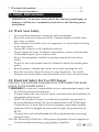
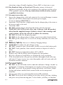
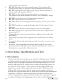
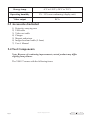
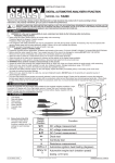
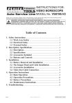
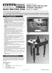
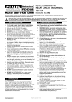
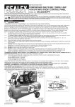
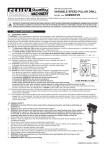
Instructions for: video bore scope Model No. VS8197.V2 Thank you for purchasing a Sealey Heater. Manufactured to a high standard this product will, if used according to these instructions and properly maintained, give you years of trouble free performance. IMPORTANT: PLEASE READ THESE INSTRUCTIONS CAREFULLY. NOTE THE SAFE OPERATIONAL REQUIREMENTS, WARNINGS AND CAUTIONS. USE THIS PRODUCT CORRECTLY AND WITH CARE FOR THE PURPOSE FOR WHICH IT IS INTENDED. FAILURE TO DO SO MAY CAUSE DAMAGE AND/OR PERSONAL INJURY AND WILL INVALIDATE THE WARRANTY. PLEASE KEEP INSTRUCTIONS SAFE FOR FUTURE USE. Table of Contents 1. Safety Instructions................................................................................2 1.1 Work Area Safety........................................................................2 1.2 Electrical Safety..........................................................................2 1.3 Battery Safety..............................................................................3 1.4 Personal Safety............................................................................3 2. Description, Specifications and Tool Components.............................4 2.1 Description...................................................................................4 2.2 Specifications...............................................................................5 2.3 Accessories Included...................................................................6 2.4 Tool Components.........................................................................7 2.5 Buttons and Ports........................................................................8 3. Installation and Connection...............................................................10 3.1 The Imager Head and Cable Installation...............................10 3.2 Accessories Installation.............................................................10 3.3 SD Card Installation.................................................................11 3.4 USB Cable Connection.............................................................11 3.5 Video-Out Cable Connection...................................................11 3.6 Earphone Connection...............................................................11 4. Battery Charging Precautions...........................................................12 4.1 Battery Charging Safety...........................................................12 4.2 Battery and Charger Specifications........................................12 4.3 Charger Inspection...................................................................12 4.4 Battery Charging Procedures..................................................13 5. Operation Instructions.......................................................................14 5.1 Basic Operation.........................................................................14 5.2 Operation Precautions..............................................................15 5.3 Tool Inspection..........................................................................16 5.4 Tool and Work Area Set-Up.....................................................17 5.5 On Screen Navigation...............................................................18 5.6 Icons...........................................................................................24 5.7 Software Update........................................................................31 6. Troubleshooting...................................................................................32 Page 1 Original Language Version VS8197.V2 Issue: 1 - 23/11/11 7. Warranty Information........................................................................32 7.1 Service Procedures....................................................................32 1.Safety SafetyInstructions Instructions 1. IMPORTANT: To prevent electric shock, fire and/or personal injury or damage, read this user’s manual first and observe the following safety instructions. 1.1. Work Area Safety • • • • • • • • • Always perform automotive testing in a safe environment. Keep your work area clean and well lit. Cluttered benches and dark areas may cause accidents. Keep clothing, hair, hands, tools, test equipment, etc. away from all moving or hot engine parts. Operate the scope in a well-ventilated work area. Do not operate the scope in explosive atmospheres, such as in the presence of flammable liquids, gases, or heavy dust. Keep a fire extinguisher suitable for gasoline/chemical/electrical fires nearby. Do not use the scope around corrosive chemicals which can ruin the photo quality. Keep bystanders, children and visitors away while operating the tool. Keep the scope dry, clean, free from oil, water and grease. Use a mild detergent on a clean cloth to clean the outside of the scope when necessary. 1.2. Electrical Safety For Use Of Charger USE ONLY THE SUPPLIED CHARGER PLUG FOR CONNECTING Bore scope TO THE POWER SUPPLY. WARNING! It is the user’s responsibility to read, understand and comply with the following electrical instructions: • You must ensure the risk of electric shock is minimised by the installation of appropriate safety devices. • An RCCB (Residual Current Circuit Breaker) should be incorporated in the main distribution board. We also recommend that an RCD (Residual Current Device) is used with all electrical products, particularly portable equipment which is plugged into an electrical supply not protected by an RCCB. • You must also read and understand the following instructions concerning electrical safety. 1.2.1.The Electricity At Work Act 1989 requires all portable electrical appliances, if used on business premises, to be tested by a qualified Page 2 Original Language Version VS8197.V2 Issue: 1 - 23/11/11 electrician, using a Portable Appliance Tester (PAT), at least once a year. 1.2.2.The Health & Safety at Work Act 1974 makes owners of electrical appliances responsible for the safe condition of the appliance and the safety of the appliance operator. If in any doubt about electrical safety, contact a qualified electrician. 1.2.3.You must ensure that you: Inspect the charger plug, cable and connector for wear and damage to ensure items are safe before connecting to the mains power supply. If worn or damaged DO NOT use. Important: Check that the voltage marked on the charger plug is the same as the power supply to be used. Uncoil the cable. DO NOT pull the charger plug from the mains socket by the lead. WARNING! DO NOT use any other type of charger with this product, other than the supplied charger. Failure to observe this warning could result in injury and or fire and will invalidate the warranty. DO NOT try to take the charger plug apart. DO NOT use the charger plug to charge or power any other electrical item. DO NOT get the charger wet, or use in wet, damp conditions (for indoor use only). 1.3 Battery Safety (Also see 4.1 Battery Charging Safety) WARNING! To reduce the risk of burns or fire: DO NOT Attempt to open, disassemble, modify or service the battery pack. DO NOT Crush, puncture, short external contacts or dispose of in fire or water. DO NOT Expose to temperatures above 60°C (140°F). Replace only with the battery pack designated for this product. Recycle or dispose of used battery as stipulated by local regulation. If the electrolyte in the cells gets on your skin, thoroughly wash with soap and water. If it gets in your eyes, rinse thoroughly with cool water and seek immediate medical attention. DO NOT use the tool while tired or under the influence of drugs, alcohol, or medications. A moment of interruption can result in serious personal injury. DO NOT over-reach. Keep proper footing and balance at all times. Proper footing and balance enables better control of the tool in unexpected situations. Always wear safety eye protection that meets ANSI standards. DO NOT Do not wear loose clothing or jewellery. Keep your hair, clothing, and gloves away from moving parts. Loose clothes, jewellery, or long hair 1.4 Personal Safety Page 3 Original Language Version VS8197.V2 Issue: 1 - 23/11/11 7 7 • can be caught in moving parts. DO NOT place the tool on any unstable surface. The tool may fall causing serious injury to a person or serious damage to the tool itself. DO NOT spill liquid on the display units. Liquid increases the risk of electric shock and damage to the tool. DO NOT use the tool for personal or medical use in any way. The product is not shock-resistant. Do not use it as a hammer or drop it. 7 7 7 7 7 DO NOT use the bore scope if dropped and/or damaged. DO NOT operate near live electrical wires. DO NOT operate near moving parts such as pulleys, motors, gears or fans etc. DO NOT bend the bore scope shaft tighter than 2.5 inch radius (5 inch diameter). DO NOT expose the bore scope housing to water or other liquids. DO NOT insert the bore scope shaft into locations whose temperature is greater than 45°C. Maintain the bore scope in good and clean condition for best and safest performance. A full range of personal safety equipment is available from your Sealey dealer. Account for all tools and parts being used and do not leave any in, or near, the engine. Be alert to your surrounding environment while using the bore scope. Note the location of the object to be inspected and determine a route to it. Bend the bore scope shaft to follow the route. 7 2. Description, Specifications and Tool 2.1 Description 9 Page 4 Feature packed professional borescope with Ø5.5x1000mm probe. Capable of displaying and storing both video and still images on internal or external memory card. Crisp images displayed on 89mm high resolution TFT LCD display with digital zoom control and on-screen horizontal/flip features for use with side-view mirrors. CMOS camera with adjustable 4xLED array allows fine control of light output and clearer pictures. SD Memory slot, USB and AV out slots ensure that the images can be easily transferred between the scope and other devices. Menu driven software with multilingual capabilities. Suitable for internal inspection of cylinder head bores and vehicle compartments/components. Ideal, for the close inspection of engines, machinery, buildings and infrastructure. Powered by internal lithium-ion Original Language Version VS8197.V2 Issue: 1 - 23/11/11 battery pack giving up to 5 hours continuous use. Supplied in foam-lined carry-case. 2.2 Specifications Recommended use Indoor Optimal viewing Distance 3/8” to 12” (0.95cm to 30cm) Image capture 640 x 480 Screen type display 3.5” TFT LCD Display resolution 320 x 240 Power supply Built-in rechargeable lithium-ion battery pack (3.7 Volt) Estimated battery life 5 hours of continuous use Dimensions 255 x 108 x 36mm (10” x 4.25” x 1.42”) Weight Net: 0.6kg (1.3lbs);Gross: 2.6kg (5.7lbs) Recording medium Internal memory or SD card (SD card is optional and not included) Image controls Zoom, low light vision Lighting Fully adjustable LED Cable reach 1m (3’) -- expandable to 8m (26’) w/optional extensions Imager head 5.5mm (0.22”) waterproof Imager head and cable to 3m (10’) Additional ports USB, video out and earphone ports Operating temp. Main unit: 32°F to 113°F (0°C to 45°C); Cable: 14°F to 176°F (-10°C to 80°C) Page 5 Original Language Version VS8197.V2 Issue: 1 - 23/11/11 Storage temp. -4°F to 158°F (-20°C to 70°C) Operating humidity 5% - 95% non-condensing (display unit) Video output RCA 2.3 Accessories Included 1) 2) 3) 4) 5) 6) 7) Protective carrying case USB cable Video-out cable Charger Magnet and mirror Imager head and cable (5.5mm) User’s Manual 2.4 Tool Components Note: Because of continuing improvements, actual product may differ slightly from pictures. The VS8197 comes with the following items: Page 6 Original Language Version VS8197.V2 Issue: 1 - 23/11/11 Fig. 1 1) 2) 3) 4) 5) LCD Screen – Indicates still images and videos. Cable – Connects to the tool while in use. Cable Connector – Connects the display unit to the imager head and cable. Imager Head – Connects to the cable to view real time images. Rubber Boot – Protects the tool from drop, abrasion, etc. Fig. 2 6) Accessory Magnet – Picks up small metal objects such as dropped rings or screws on the floor. Page 7 Original Language Version VS8197.V2 Issue: 1 - 23/11/11 7) Accessory Mirror – Helps users look around corners and see inside the unreachable areas. 2.5 Buttons and Ports Fig. 3 A. B. C. D. E. F. Page 8 Power Button – Turns on/off the tool. Setting/Back Button – Moves to the primary settings screen, while pressing again will return to the last viewed screen. Camera/Video Button – Helps capturing a photo while pressing again will capture a video. Play Button – Moves to play captured photos and videos. Bin/Reverse Button – Deletes captured photos and videos in the play mode. Pressing again will control the direction of the real-time image and video in the live screen. The real-time image and video will do a horizontal reverse or a vertical reverse. LEFT Arrow LED Lighting Adjusting Button – Uses left arrow button to decrease LED brightness in the camera mode. Original Language Version VS8197.V2 Issue: 1 - 23/11/11 G. H. I. J. K. L. M. N. Page 9 RIGHT Arrow LED Lighting Adjusting Button – Uses right arrow button to increase LED brightness in the camera mode. UP Arrow Zoom Adjusting Button – Uses up arrow button to zoom in while in the camera mode. DOWN Arrow Zoom Adjusting Button – Uses down arrow button to zoom out while in the camera mode. DC Power Source Port – Connects the tool to the mains with the supplied charger for battery charging. Video-out Port – Connects the tool to a TV with the supplied video-out cable to view real time images. Earphone Port – Inserts the optional earphone with microphone into the earphone port to help recording. Charging Indicator Light – When the battery is charging, the charging indicator light will be red. When the battery is fully charged, the charging indicator light will be green. Mini USB Port – Connects the tool to a computer with the supplied USB cable to upload and view captured photos and videos. Original Language Version VS8197.V2 Issue: 1 - 23/11/11 3. Installation and Connection 3. Installation and Connection 3.1 The Imager Head and Cable Installation To use the tool, the imager head and cable must be connected to the display unit. To connect the cable to the display unit, make sure the key and slot (Fig. 4) are properly aligned. Once they are aligned, tighten the knurled knob to hold the connection firmly in place. Fig.4 3.2 Accessories Installation The two accessories include a magnet and a mirror (Fig.2). Both of the accessories are attached to the imager head in the same manner, here we are showing you how to attach the accessories using a magnet as an example. Hold the imager head as shown in Fig.5 Fig. 5 Screw the accessory onto the imager head to fix (Fig. 6). Page 10 Original Language Version VS8197.V2 Issue: 1 - 23/11/11 Fig. 6 3.3 SD Card Installation NOTE: SD card slot provides for additional memory (not included). To insert an SD card into the SD card slot, make sure the contacts are facing towards slot and the angled portion of the card is facing down. When the SD card is installed, a small SD card icon will appear at the top right hand corner of the screen. To remove an SD card, gently push the SD card inward and then release to eject it from the card slot. 3.4 USB Cable Connection Use the supplied USB cable to connect the tool to a PC to upload and view captured photos and videos. A “USB Connected” message will appear on the screen. 3.5 Video-Out Cable Connection Insert the video-out cable into the video-out port of the tool and the other end of the cable into the video-in port of a TV, the LCD screen will output a high quality real time image. 3.6 Earphone Connection Connect the optional earphone with microphone to the earphone port of the tool. Page 11 Original Language Version VS8197.V2 Issue: 1 - 23/11/11 4. 4.Battery BatteryCharging ChargingPrecautions Precautions IMPORTANT: To reduce the risk of serious injury, read these precautions and the label on charger carefully before using. 4.1 Battery Charging Safety DO NOT use charger if it has been dropped or damaged in any way. Charge battery in temperatures above 41°F (5°C) and below 113°F (45°C). Use the supplied charger only. DO NOT allow anything to cover the charger while in use. Unplug the charger from outlet before attempting any maintenance or cleaning. DO NOT store charger in damp, wet or explosive environment. DO NOT open charger housing. Have repairs performed only at authorised suppliers. DO NOT charge battery near fire or in sunlight. Proper care will prevent serious damage to the charger. 4.2 Battery and Charger Specifications Input Output Battery Type Battery Capacity Input Current Charging Time Cooling 100-240 VAC/12 VDC 50/60Hz 5V DC 3.7V lithium-ion 4200 mAh 0.3A/1A (DC) 5-6 hours Passive convection cooling (No fan) 4.3 Charger Inspection CAUTION: Before using, inspect the charger for damage. Set up charger according to these procedures to reduce the risk of injury from electric shock, fire and other causes and prevent tool damage. Page 12 Make sure charger is unplugged. Inspect the power cord and charger for damage, modifications, broken, worn, missing, or misaligned parts. If any problems are found, do not use the charger until the parts have been repaired or replaced. Clean any oil, grease or dirt from the tool especially on the buttons. Original Language Version VS8197.V2 Issue: 1 - 23/11/11 This helps prevent the tool from slipping from your hands and allows proper ventilation. Inspect if the warning label on charger’s surface is intact and readable. Select appropriate location for charger before using. Check work area for: • The charger must be between 41°F (5°C) and 113°F (45°C) for charging. • Inspect that the plug fits correctly into the desired outlet. • The charger needs a clearance of at least 4” (10cm) on all sides to maintain a proper operating temperature. 4.4 Battery Charging Procedures NOTE: New battery reaches full capacity after approximately 5 charging and discharging cycles. 1 The tool has a 3.7V built-in lithium-ion rechargeable battery. When the battery is low, a “Battery critically low!” message appears and suggests you to charge the battery. There are two means of charging battery: 1) To charge battery by charger: Locate the DC power port on the tool. With dry hands, connect the tool to the mains charger to start charging. 2) To charge battery by USB cable: Locate the USB port. With dry hands, connect the tool to a PC with USB cable to start charging. • The battery will begin charging automatically. Whilst the battery is charging, the charging indicator light will illuminate red. • When the battery is fully charged, the charging indicator light will illuminate green and the charger will stop charging. • Once the battery is charged, it is ready to be used. There is no risk of over-charging the battery. Unplug charger from outlet once charging completes. • Page 13 Original Language Version VS8197.V2 Issue: 1 - 23/11/11 5. 5.Operation OperationInstructions Instructions IMPORTANT: Always wear safety eye protection to protect your eyes against dirt and other objects. Follow operation instructions to reduce the risk of injury from electric shock, entanglement and other causes. 5.1 Basic Operation 22B NOTE: When in operation, the cable can be bent into different shapes. This may help you operate in confined areas. 1) 2) 3) 4) 5) 6) 7) 8) 9) 10) 11) Page 14 Hold the tool with LCD screen facing you and press the Power button to turn it on. Wait for two seconds, a splash screen displays while booting up, followed by live screen. Press OK button to capture photos while in the camera mode; Press OK button to begin capturing videos while in the video mode. You should press Camera/Video button to switch the two modes. Press UP and DOWN arrow buttons to zoom in or out while in the camera mode where you can see a zoom indicator bar as you adjust zoom. Press LEFT and RIGHT arrow buttons to increase or decrease LED brightness while in the camera mode where you can see a brightness indicator bar as you adjust LED light intensity. Press Play button to view captured photos and videos. Press Bin button to delete captured photos and videos when playing back captured photos and videos. Press Rotary button to rotate the real time images and videos 180° every time in the live screen. Press Setting/Back button to Setup mode or return to the last viewed screen. Use the supplied accessories to provide application flexibility. Use the supplied USB cable to connect the tool to a PC to upload and view captured photos and videos. Connect the supplied video-out cable to video-out port of the tool and the other end of the cable to the video-in port of a TV to view a high quality real time image. Original Language Version VS8197.V2 Issue: 1 - 23/11/11 5.2 Operation Precautions • • • • • • • • • • • • • • • • • Page 15 Use the tool only as directed. Do not operate the tool unless the user’s manual has been read thoroughly and proper training has been completed. The display unit is not waterproof. The imager head and cable are waterproof, but not acid-proof or fireproof. Avoid submersing the imager head and cable into corrosive, oily places and be sure to keep the imager head and cable away from high temperature objects. Do not immerse the tool and display unit in water. Do not use excessive force to insert or withdraw the imager head and cable. This may result in damage to the tool or inspection area. Do not use the imager head and cable to modify surroundings, clear pathways or clogged areas. Do not place the imager head and cable into anything or anywhere that may contain a live electric charge or moving parts, which increase the risk of electric shock or entanglement injuries. Do not use the tool for personal inspection or medical use in any way. This is not a medical tool. Do not eat or smoke while operating the tool. Use hot, soapy water to wash hands and other exposed skin after using the tool to inspect drains and other areas that may contain chemicals or bacteria. When the inspection is completed, carefully withdraw the imager head and cable from inspection area. Store idle components out of the reach of children and other untrained persons. Maintain the tool with care. Properly maintained tools are less likely to cause injury. Do not drop the tool, if the tool is dropped accidently, check for the breakage and any other conditions that may affect its operation. Use only accessories that are recommended by the manufacturer for the tool. Dry your hands when operating the tool or charging battery. Always use appropriate personal protective equipment while handling and using the tool. Appropriate personal protective equipment always includes safety glasses and gloves, and may include latex or rubber gloves, face shields, goggles, protective clothing, respirators and steel toed footwear. Protect against excessive heat. The tool should be kept away from heat sources such as radiators, stoves or others that produce heat. Do not use the tool near moving machinery or areas where the temperature will exceed 113°F (45°C). Store the tool, charger and all cables in a locked area out of the reach of children and people unfamiliar with tool. Original Language Version VS8197.V2 Issue: 1 - 23/11/11 5.3 Tool Inspection WARNING: Before using, inspect the scope and correct any problems to reduce the risk of serious injury from electric shock and other causes and prevent tool damage. • • • • • Make sure the power is OFF. Clean any oil, grease or dirt from the tool, especially on the buttons and ports. This helps prevent the tool from slipping from your hands. Inspect the imager head lens for condensation. To avoid damaging the tool, do not use the tool if condensation forms inside the imager head. Let the water evaporate before using again. Inspect the full length of the cable for cracks or damage. Make sure the connections between the display unit and imager head and cable are tight. All connections must be properly assembled for the cable to be waterproof. NOTE: Please check following methods to avoid injury. • FOR WALLS: For inspecting the inside of walls, be sure to close the electrical circuit breaker to the whole house before using the tool. • FOR PIPES: If you suspect a metal pipe could contain electric cables, have a qualified electrician check the pipe before using. • FOR AUTOMOBILES: Be sure the automobile is not running during inspection. Metal and liquid under the hood may be hot. Don’t get oil or fuel on the imager head. Page 16 Original Language Version VS8197.V2 Issue: 1 - 23/11/11 5.4 Tool and Work Area Set-Up CAUTION: Set up the scope and work area according to these procedures to reduce the risk of injury from electric shock, entanglement, and other causes and prevent tool damage. 1. • • 2. 3. • • • • • 4. 5. Check work area for: Sufficient lighting. Do not work in area until flammable sources have been identified and corrected. The tool is not explosion proof and can cause sparks. Check the area and determine if VS8179 is the correct tool for the job. Check the access points to the area. Check there is no electricity supplied to the area to be inspected. The imager head and cable are waterproof to a depth of 3m (10'). Greater depths may cause ingress to the imager head and cable and damage the tool. The display unit is not waterproof and should not be exposed to wet conditions. Check if any chemicals are present, especially in the case of drains. Chemicals may damage or degrade the tool. Check the temperature of the area. The working temperature of the tool is between 32°F (0°) and 113°F (45°). Check if any moving parts are present in the area. Make sure the tool has been properly inspected. Install the correct accessories for use in the appropriate application. CAUTION: Make sure the tool has been powered off before performing maintenance. • • • • • • Tool maintenance must be performed only by qualified repair personnel. Maintenance performed by unqualified repair personnel could cause injury. When maintaining, use only identical replacement parts. Use of unauthorized parts or failure to follow maintenance instructions will invalidate warranty. Do not attempt to take the tool apart. Follow instructions to change accessories. Do not use acetone to clean the tool. Instead, use only alcohol to swab the connections. Avoid rubbing too hard on the LCD screen. After using, wipe the display unit clean gently with a dry cloth. Always handle the tool with care. It is not shock-resistant. Page 17 Original Language Version VS8197.V2 Issue: 1 - 23/11/11 5.5 On Screen Navigation 1) Splash Screen When the tool is powered on, the first screen displayed is referred to as the splash screen. This screen tells you the tool is booting up. Once the tool is fully powered up, the screen will automatically switch to the live screen. 2) Live Screen The live screen is where you will do most of your work. A live image of what the imager head sees is displayed on the screen. You can zoom, adjust LED brightness, rotate images and videos, view and capture photos and videos from this screen. 3) Switching from Still Image Capture to Video Capture The tool defaults to still image capture when powered on. Press Video/ Camera button to switch between still image capture and video capture as required. 4) Adjusting LED Brightness Pressing RIGHT and LEFT arrow buttons on the key pad (in the still camera mode) will increase or decrease the LED brightness. A brightness indicator bar will be displayed on the screen as you adjust brightness. (Fig. 7) Fig. 7 Page 18 Original Language Version VS8197.V2 Issue: 1 - 23/11/11 5) Zooming Press UP and DOWN arrow buttons while in the still camera mode to zoom in or out. A zoom indicator bar will be displayed on the screen as you adjust zoom. (Fig. 8) Fig. 8 B 6) Entering the Primary Settings Screen Pressing the Setting button while in the live screen will take you to the primary settings screen. (Fig. 9) Pressing Back button at any point will take you back to the live screen. Fig. 9 Page 19 Original Language Version VS8197.V2 Issue: 1 - 23/11/11 7) Capturing a Photo When in the live screen, make sure the camera icon is present at the top left portion of the screen. (Fig. 10) Press OK button to capture a photo and the photo will be saved to the internal memory or SD card. You will also notice that the number of total photos displays below the camera icon. The number will increase or decrease as different capacity SD cards are used or the photo quality is adjusted. Fig. 10 8) Capturing a Video While in the live screen, make sure the video icon is present at the top left portion of the screen. (Fig. 11) Press OK button to start capturing video. You will notice that a Rec. icon appears at the top right portion of the screen, just below battery capacity icon. This shows that video is capturing. The time at the top left portion, just below video icon will begin counting down. This indicates how much video you can store in the internal memory or SD card. Press OK button again to stop capturing a video. Fig. 11 • It may take a few seconds to save the captured video to the internal memory or SD card. 9) Playing Back and Deleting Captured Photos and Videos Pressing Play button on the key pad will display two modes for you to select. Photos and videos that were captured will be displayed on the screen. Use Page 20 Original Language Version VS8197.V2 Issue: 1 - 23/11/11 LEFT and RIGHT arrow buttons to move from Photo mode to Video mode. (Fig. 12 and Fig. 13) Fig. 12 Fig. 13 Page 21 While in the photo mode, press OK button and use LEFT and RIGHT arrow buttons to play back captured photos one after another, use UP and DOWN arrow buttons to zoom in and out. While in the video mode, press OK button and use LEFT and RIGHT arrow buttons to play back captured videos one after another. Original Language Version VS8197.V2 Issue: 1 - 23/11/11 • While in the photo mode, selecting a photo and pressing OK button will appear record mode in the middle of the screen. (Fig. 14) Fig. 14 • Inserting the optional earphone with microphone and pressing OK button will begin recording (Fig. 15) and timing. Fig. 15 • Press OK button to stop recording and then the“ • Then press OK button to play recording while pressing OK again will pause playing record mode. (Fig. 16 and Fig. 17) ” icon will appear. Fig. 16 Fig. 17 • If you wish to delete the recording, use LEFT and RIGHT arrow buttons to select “ ” icon. (Fig. 18) Fig. 18 • While in the video mode, select a video which has been recorded and press OK button to start playing recording while pressing OK again will pause recording. Pressing LEFT button will fast rewind recording while press RIGHT button will fast forward recording. Press DOWN button will stop Page 22 Original Language Version VS8197.V2 Issue: 1 - 23/11/11 playing recording. • Either in the Photo mode or in the Video mode, press Bin button to delete captured photos and videos, and a “Are you sure you want to delete this file?” message appears on the screen. (Fig. 19 and Fig. 20). Use LEFT and RIGHT arrow buttons to select Yes or No, then press OK button to save your selection. Fig. 19 Fig. 20 • Page 23 When you delete all the photos and videos, a “No Files Available” message appears on the screen. Original Language Version VS8197.V2 Issue: 1 - 23/11/11 10) Entering the Secondary Settings Screen While in the Primary Settings Screen (Fig. 9), select Advanced Settings from Setup and then press OK, you will enter the secondary settings screen (Fig.21) where you can set Date and Time, Restore Defaults and select Language as needed. Pressing Back button at any point will bring you back to the primary settings screen and pressing it again will return you to the live screen. Fig. 21 5.6 Icons 1) – Battery Capacity – Fully charged battery. 2) – SD Card – Indicates an SD card has been inserted into the tool. 3) – Still Camera – Indicates the tool is operating in still camera mode. 4) – Video Camera – Indicates the tool is operating in video camera mode. 5) – Indicates you to begin playing recording in the photo play mode. 6) – Indicates you to start recording in the photo record mode. 7) – Indicates you are recording in the photo record mode. 8) – Indicates play recording in the photo record mode. 9) – Indicates pause playing recording in the photo record mode. 10) – Indicates cancel recording in the photo record mode. 11) – Displays advanced settings. Advanced Settings is the default mode from Setup menu. • Page 24 Press Setting button to enter Setup. Original Language Version VS8197.V2 Issue: 1 - 23/11/11 Fig. 22 • Select Advanced Settings from Setup and press OK button to modify advanced settings. • When necessary, use UP and DOWN arrow buttons to select Date and Time, Restore Defaults and Language from Advanced Settings. 12) Fig. 23 2 – Displays colour or black/white. Colour is the default mode. • Page 25 Select Color or Black/White from Setup and press OK button. Original Language Version VS8197.V2 Issue: 1 - 23/11/11 Fig. 24 • Use LEFT and RIGHT arrow buttons to select from Colour mode to Black/ White mode, then press OK button to save your selection. • If you wish to view or capture colour images and videos, select Colour from Setup. Fig. 25 • If you wish to view or capture black/white images and videos, select Black/ White from Setup. Fig. 26 13) 2 – Asks if you would like to format media. Page 26 Original Language Version VS8197.V2 Issue: 1 - 23/11/11 • Select Format Media from Setup and press OK button. Fig. 27 • If you wish to format media, select Format Media from Setup and press OK button and then use LEFT and RIGHT arrow buttons to select Yes, then press OK button to save your selection. Fig. 28 • If you do not wish to format media, use LEFT and RIGHT arrow buttons to select No to return to previous menu. Fig. 29 • Page 27 If you select Yes, a message “Warning - this will erase ALL files in memory” appears on the screen. Press OK button to save your selection and return to previous menu. Original Language Version VS8197.V2 Issue: 1 - 23/11/11 Fig. 30 • If you do not wish to format media, select No to return to previous menu. Fig. 31 14) • 2 – Displays firmware version. Select Help from Setup and press OK button to display Firmware Version. Fig. 32 Page 28 Original Language Version VS8197.V2 Issue: 1 - 23/11/11 Fig. 33 15) • – Sets date and time. When you enter Advanced Settings, select Date and Time and press OK button. Fig. 4 • Use UP and DOWN arrow buttons to set exact date and time, while using LEFT and RIGHT arrow buttons to move from one item to another and press OK button to save. Fig. 35 16) • Page 29 – Asks if restore factory defaults. Select Restore Defaults from Advanced Settings and press OK button. Original Language Version VS8197.V2 Issue: 1 - 23/11/11 Fig. 36 • If you wish to restore factory defaults, use LEFT and RIGHT arrow buttons to select Yes or No, then press OK button to save your selection. Fig. 37 • If you do not wish to restore factory defaults, select No to return to previous menu. Fig. 38 17) Page 30 – Displays multi-language interface. Original Language Version VS8197.V2 Issue: 1 - 23/11/11 English is the default language. • Select Language from Advanced Settings and press OK button. Fig. 39 • Use LEFT and RIGHT arrow buttons to switch between English, Spanish, French, German and Dutch and select the desired language and press OK button to save your selection. Fig. 40 5.7 Software Update NOTE: The tool supports software updates. 1) 2) 3) 4) Page 31 Format your SD card to FAT file format on a computer. Visit our website www.sealey.co.uk and download software update file to your SD card. Insert your SD card into the SD card slot. (See 3.3 SD Card Installation) Press UP arrow button and then press Power button to turn on the tool. The screen will flash and software will update automatically. Original Language Version VS8197.V2 Issue: 1 - 23/11/11 6. 6.Troubleshooting Troubleshooting SYMPTOMS Display is on, but does not show image. POSSIBLE REASONS Cable connection is loose. SOLUTIONS Check and reattach. Imager head is covered by debris. Inspect the imager head and clean if necessary. LEDs on imager head are dim at max brightness, display changes between black and white, color display turns itself OFF after a short period. Low battery. Charge battery. The tool will not turn on. Dead battery. Charge battery. 2 7. Warranty Information 7. Warranty Information Limited One Year Warranty Sealey warrants to its customers that this product will be free from all defects in materials and workmanship for a period of one (1) year from the date of the original purchase, subject to the following terms and conditions: 1) The sole responsibility of Sealey under the Warranty is limited to either the repair or, at the option of Sealey, replacement of the tool at no charge with Proof of Purchase. The sales receipt may be used for this purpose. 2) This warranty does not apply to damages caused by improper use, accident, flood, lightning, or if the product was altered or repaired by anyone other than the Manufacturer’s Service Centre. 3) Sealey shall not be liable for any incidental or consequential damages arising from the use, misuse, of the tool. 4) All information in this manual is based on the latest information available at the time of publication and no warranty can be made for its accuracy or completeness. Sealey reserves the right to make changes at any time without notice. 7.1 Service Procedures If you have any questions, please contact your local store, distributor or visit our website at www.sealey.co.uk. If it becomes necessary to return the tool for repair, contact your local distributor for more information. Page 32 Original Language Version VS8197.V2 Issue: 1 - 23/11/11 Environmental Protection. Recycle unwanted materials instead of disposing of them as waste. All tools, accessories and packaging should be sorted, taken to a recycle centre and disposed of in a manner which is compatible with the environment. When the product is no longer required, it must be disposed of in an environmentally protective way. Contact your local solid waste authority for recycling information. Battery Removal. Open the rear cover by removing the six cover screws using a Phillips head screwdriver. Lift the battery from the meter and unclip from the battery socket. Handle the Li-ion battery with care, do not puncture or expose to heat. Put the cover back in place. Secure with the screws. Dispose of batteries according to local authority guidelines. Under the Waste Batteries and Accumulators Regulations 2009, Jack Sealey Ltd are required to inform potential purchasers of products containing batteries (as defined within these regulations), that they are registered with Valpak’s registered compliance scheme. Jack Sealey Ltd’s Batteries Producer Registration Number (BPRN) is BPRN00705 NOTE: It is our policy to continually improve products and as such we reserve the right to alter data, specifications and component parts without prior notice. IMPORTANT: No liability is accepted for incorrect use of this product. WARRANTY: Guarantee is 12 months from purchase date, proof of which will be required for any claim. INFORMATION: For a copy of our latest catalogue and promotions call us on 01284 757525 and leave your full name and address, including postcode. Sole UK Distributor, Sealey Group, Kempson Way, Suffolk Business Park, Bury St. Edmunds, Suffolk, IP32 7AR Page 33 Original Language Version 01284 757500 01284 703534 Web email www.sealey.co.uk [email protected] VS8197.V2 Issue: 1 - 23/11/11 EC DECLARATION OF CONFORMITY We the sole importers into the UK, hereby declare that the equipment described below Video Borescope Ø5.5mm Description and Function: .................................................................................................................................................. VS8197.V2 Model/Type: ....................................................................................................................................................................... Manufacturing Date / Serial number (optional): ................................................................................................................. Manufacturer's authorised representative within the EC: Jack Sealey Ltd. Kempson Way, Suffolk Business Park, Bury St. Edmunds, Suffolk, IP32 7AR Conforms to the requirements of the following Directives, as indicated. 2006/42/EC Machinery Directive 2000/14/EC Outdoor Noise Emissions Directive 2006/95/EC Low Voltage Directive 2002/96/EC WEEE Directive 2004/108/EC EMC Directive 2002/95/EC RoHS Directive 93/68/EEC CE Marking Directive 97/23/EC Pressure Equipment Directive 2009/105/EC the Simple Pressure Vessels Directive And the following harmonised standard(s) BS EN 61000 part 4-2: 2009 BS EN 55022:2010 ………………………………………………………………………………………………....................................................... BS EN 55024: 2010 BS EN 61000 part 4-3: 2006 + A2: 2010 ………………………………………………………………………………………………....................................................... ………………………………………………………………………………………………....................................................... ......................................................................................................................................................................................... Additional technical standards and specifications (if applicable): ………………………............................................……… ........................................................................................................................................................................................ Technical file compiled by: Jack Sealey Ltd. Signed:…………………………………….. 13-Oct-2011 Date:………………………………............. Place: Bury St.Edmunds. Tim Thompson Name:………………………………………… Commercial Director Position:………………………………….... Being the responsible person appointed by the manufacturer. Page 34 Original Language Version VS8197.V2 Issue: 1 - 23/11/11