1
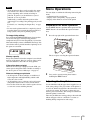
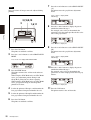
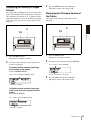
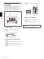
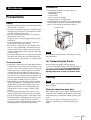
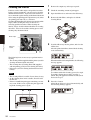
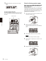
3-297-459-11(2)
Digital Photo Printer
Operating Instructions
UP-DR200
© 2008 Sony Corporation
Owner's Record
The model and serial numbers are located at the rear.
Record these number in the space provided below.
Refer to these numbers whenever you call upon your
Sony dealer regarding this product.
You are cautioned that any changes or modifications not
expressly approved in this manual could void your
authority to operate this equipment.
All interface cables used to connect peripherals must be
shielded in order to comply with the limits for a digital
device pursuant to Subpart B of Part 15 of FCC Rules.
Model No. ____________________
Serial No. ____________________
Warning on power connection
WARNING
To reduce the risk of fire or electric shock, do
not expose this apparatus to rain or moisture.
To avoid electrical shock, do not open the
cabinet. Refer servicing to qualified personnel
only.
THIS APPARATUS MUST BE EARTHED.
To disconnect the main power, unplug the AC
IN connector.
This symbol is intended to alert the user to
the presence of important operating and
maintenance (servicing) instructions in
the literature accompanying the
appliance.
Risk of injury
Do not touch the inside.
Hot surface
Thermal Print Head becomes a high
temperature.
For the customers in the U.S.A.
This equipment has been tested and found to comply
with the limits for a Class A digital device, pursuant to
Part 15 of the FCC Rules. These limits are designed to
provide reasonable protection against harmful
interference when the equipment is operated in a
commercial environment. This equipment generates,
uses, and can radiate radio frequency energy and, if not
installed and used in accordance with the instruction
manual, may cause harmful interference to radio
communications. Operation of this equipment in a
residential area is likely to cause harmful interference in
which case the user will be required to correct the
interference at his own expense.
2
Use a proper power cord for your local power supply.
1. Use the approved Power Cord (3-core mains lead) /
Appliance Connector / Plug with earthing-contacts
that conforms to the safety regulations of each
country if applicable.
2. Use the Power Cord (3-core mains lead) / Appliance
Connector /Plug conforming to the proper ratings
(Voltage, Ampere).
If you have questions on the use of the above Power
Cord/Appliance Connector/Plug, please consult a
qualified service personnel.
For the customers in Europe
The manufacturer of this product is Sony Corporation,
1-7-1 Konan, Minato-ku, Tokyo, Japan. The Authorized
Representative for EMC and product safety is Sony
Deutschland GmbH, Hedelfinger Strasse 61, 70327
Stuttgart, Germany. For any service or guarantee matters
please refer to the addresses given in separate service or
guarantee documents.
Table of Contents
Introduction
Features .................................................................. 4
Basic Application Example ................................ 4
Location and Function of Parts and Controls .... 4
Preparation
Supplied Accessories ............................................. 7
Connections ............................................................ 8
USB Port Connection ......................................... 8
Installing the Printer Driver ................................ 8
Operation
Loading the Paper Roll and Ink Ribbon ............. 9
Loading the Paper Roll and Ink Ribbon ............. 9
Attaching the Scrap Receptacle ........................ 13
Attaching the Output Tray ................................ 13
If the Ink Ribbon Breaks during Use ............... 15
Removing the Ink Ribbon and Paper ............... 16
Printing from the Computer ............................... 18
Menu Operations ................................................. 19
Preparation for Menu Operation ...................... 19
Adjusting the Gray Balance ............................. 19
Displaying the Quantity of Pages Printed ........ 21
Displaying the Firmware Version of the
Printer ............................................................. 21
Adjusting the Position of the Printout Image ... 22
Miscellaneous
Precautions ........................................................... 23
Safety ................................................................ 23
Installation ........................................................ 23
On Transporting the Printer .............................. 23
Cleaning ........................................................... 23
Cleaning the Interior ......................................... 24
Ink Ribbon and Paper ......................................... 27
Specifications ........................................................ 27
List of Messages ................................................... 28
Troubleshooting ................................................... 29
Index ..................................................................... 30
Table of Contents
3
Introduction
Introduction
Features
The UP-DR200 Digital Photo Printer is a dye
sublimation thermal transfer printer providing high
quality, high resolution (330 dpi), and high speed
printing of computer image data on four sizes of paper
in full color (256 gradations process and 16.7 million
colors).
Location and Function
of Parts and Controls
For more details, see the reference page numbers
enclosed in parentheses.
Front
Basic Application Example
Computer: provides
image data for printing
and printer control
signals
Output tray removed
UP-DR200 Digital Photo Printer
A ALARM indicator (page 28)
Lights in red when the system is initialized, or when
an error occurs.
B LCD (liquid crystal display) (page 18, 21, 28)
Displays the number of pages printed, or the
amount of ink ribbon remaining. Messages are
displayed when an error or warning condition
occurs.
4
Features / Location and Function of Parts and Controls
C Operation button door (page 19)
Buttons to be used for menu operation are located
under this door.
Key panel section
F Output tray adapter (page 14)
Attach this to the output tray to prevent printouts
from falling out.
Introduction
G Output slot (page 18)
Printouts are ejected from here.
H Paper door (page 10)
Open and close this when replacing paper rolls.
This does not open while printing is in progress.
I Ribbon door (page 12)
Open and close this when replacing the ink ribbon.
This does not open while printing is in progress.
J Paper door lever
Use this to open the paper door.
A EXEC button (page 20)
Press this button to print the gray scale adjustment
pattern.
When the paper and ribbon doors are open
B MENU button (page 21)
Press this button to carry out menu operations.
Pressing the MENU button changes the printer to
the off-line mode.
C Cursor buttons (page 21)
Press these buttons to select the item to be
displayed on the LCD.
D CAL (calibration) button (page 19)
Press this button to adjust the gray balance.
E PRINT STOP button (page 19)
Pressing the PRINT STOP button for more than one
second during printing results in cancelling the
number of printings set and clearing the images
stored in the memory. The printer stops printing
when the page currently printing is completed and
ejected.
A Paper core
Insert this into the paper roll.
D Output tray (page 13)
Collects printouts that are ejected.
C Paper adapter (blue)
E Output stopper (page 13)
Adjust the position according to the printing pack
in use. There are four potions to which to adjust.
B Ribbon tray
Place the ink ribbon here.
D Paper adapter (pink)
Attach the paper adapters to the printer when using
the 2UPC-R203/R205 series printing pack.
Location and Function of Parts and Controls
5
K Scrap receptacle (page 13)
Margins of empty space are crated between each
printout. These margins are cut off during printing
and dropped into this receptacle.
Introduction
Rear
L Filter cover (page 26)
The filter for the printer’s cooling fan is attached to
this cover.
M
USB connector (page 8)
Connects to a computer equipped with USB
interface (conforming to USB 2.0) via the supplied
USB cable.
N ! POWER switch (page 18)
Press this to turn the printer on and off.
O - AC IN connector (page 8)
Connect the power cord here.
6
Location and Function of Parts and Controls
Preparation
Supplied Accessories
Make certain you have received the following
accessories:
Output tray adapter (1)
Scrap receptacle (1)
Cleaning ribbon (1)
Ribbon tray* (1)
Paper core* (1)
Paper adapter (blue)* (1)
Paper adapter (pink)* (1)
Preparation
Output tray (1)
CD-ROM (1)
USB cable (1)
Before Using This Printer (1)
Software License Agreement (1)
Warranty Card (1)
Service and Customer Support
Information (1)
* The paper core is located inside the printer and must be removed when loading or removing paper.
For details on removing the core, see “Loading the Paper Roll and Ink Ribbon” on page 9.
Notes
• When taking the printer out of the carton box, be
careful not to hurt your back.
• The packaging materials are needed when
transporting the printer, so we suggest you keep them.
• Do not transport the printer with the ink ribbon and
paper roll attached.
Supplied Accessories
7
Securing the USB cable and power cord
Connections
After connecting a USB connecting cable (supplied) to
the printer and the computer, connect the power cord.
For details about the printer connection, refer to the
manuals for the computer or other peripheral devices.
To prevent disconnection of the USB cable and power
cord from accidental pulling, be sure to secure the cables
with the cable clamps when connecting them to the
printer.
To secure the USB cable
Wrap the cable clamp around the USB cable, and fasten
it securely as shown.
USB Port Connection
Preparation
Notes
• Follow the connection procedures described in the
computer manual.
• Make sure that the interface cable is connected
securely at both ends.
• The printer drive software provided with the printer is
not suitable for using the printer connected to a
network.
• Operation of the printer is not guaranteed for
connection to a USB hub.
To secure the power cord
Wrap the cable clamp around the power cord, and fasten
it securely as shown.
UP-DR200
Installing the Printer Driver
to
to - AC IN
connector
(USB) connector
AC power cord
(not supplied)
to wall outlet
USB connecting cable
(supplied)
Computer
8
Connections
To install the printer driver, follow the instructions in the
ReadMe.txt file and the install guide on the supplied
CD-ROM.
• Hold the paper roll with both hands so that you do not
drop it, because it is heavy. Dropping may result in an
injury.
Operation
Loading the Paper Roll
and Ink Ribbon
This section describes how to load the paper roll and ink
ribbon in the preparation to start printing, after
connecting the printer as described on page 8.
Handling the Paper Roll and Ink Ribbon
• Each printing pack contains two sets of the ink ribbon
and paper roll combination. Use the ink ribbon and the
paper roll in the carton as a set. Do not mix with other
varieties of ribbon or paper roll. (See “Ink Ribbon and
Paper” on page 27.)
• The number of sheets that can be printed differs
depending on the printing pack. One set of the ink
ribbon and paper roll allows you to print the following
number of sheets.
Printing 2UPCpack
R203
series
2UPCR204
series
2UPCR205
series
2UPCR206
series
Print
capacity
700 sheets
400 sheets
350 sheets
102×152
mm
127×178
mm
152×203
mm
770 sheets
Print size 89×127
mm
3.5×5
inches
4×6 inches 5×7 inches
6×8 inches
• Do not replace the printing pack if it has only been
partially used. If the paper roll or ink ribbon is
replaced after only partial use, the above print
capacities are not guaranteed.
• When setting the paper roll down, place it vertically as
shown. If you place the paper roll horizontally, the
paper may roll around and fall. This may cause an
injury.
• Do not detach the black and white spools of the ink
ribbon until you start loading the ink ribbon.
• An IC chip is embedded in the black spool. Do not
touch the terminals on the IC chip with your hands
or metal objects, and do not dent, drop, or
otherwise apply shock to the IC chip. Doing so may
cause the ink ribbon to become unusable.
Operation
Notes
Hold the paper roll with both hands.
White spool
Black spool
IC chip
Loading the Paper Roll and Ink
Ribbon
When you use the printer for the first time, load the
paper roll and ink ribbon.
For detailed information on how to remove the paper
and ink ribbon, see “Removing the Ink Ribbon and
Paper” on page 16.
Before loading the paper roll and ink ribbon
Confirm that the printer is powered on. If not, turn the
printer power on.
Otherwise, the automatic paper feeding may not be done
correctly after loading of the paper roll and ink ribbon is
completed.
Also, after you have used up one paper roll, clean the
thermal head and rollers before loading a new paper roll
and ink ribbon.
For detailed information on cleaning, see “Cleaning the
Interior” on page 24.
Loading the Paper Roll and Ink Ribbon
9
Note
3
If you use the 2UPC-R204 series or 2UPC-R206 series
Printing Pack with the 152-mm (6-inch) paper width
after using the 2UPC-R203 series or 2UPC-R205 series
Printing Pack with the 127-mm (5-inch) paper width,
white stripes may appear on either side of printouts.
Be sure to clean the inside of the printer before printing
(page 24).
Insert the paper core into the paper roll.
The two sides of the paper core are the same shape.
You can insert either side.
To load the paper roll
Notes
Operation
• Be sure to remove the output tray and the scrap
receptacle before loading the paper roll.
• Be careful that your fingers and clothing are not
caught in the paper door or on the protuberance in the
opening of the door.
1
Notes
• If the edges of the paper on the roll are not aligned
before inserting the paper core, be sure to align
them while being careful not to bend or damage
them. Not doing so may result in malfunction.
Press and lower the paper door lever, hold the paper
door at the center portion, and pull the door forward
until it locks into the open position.
• If the leading edge of the paper is bent or
damaged as a result of a paper jam, for example,
be sure to use scissors to cut off the damaged
portion, as shown, before inserting the paper.
2
Remove the paper core from the printer.
• Do not bump the paper roll against hard objects or
squeeze it tightly. Doing so may bend or crease
the paper and affect print quality.
4
Depending on the width of your paper roll, attach or
remove the paper adapters.
Paper with 127-mm (5-inch) width: 2UPC-R203
series and 2UPC-R205 series Printing Pack
Attach the blue paper adapter to the left side of the
printer, and the pink paper adapter to the right side.
10
Loading the Paper Roll and Ink Ribbon
5
(When the factory is shipped, the paper adapter is
attached.)
pink
Operation
blue
Load the paper roll into the printer.
Be sure to load the paper roll with the arrow on the
seal pointing inside the printer.
Notes
• To prevent the paper roll from sliding off, hold
both sides of the paper core when loading it into
the printer.
• Do not touch the print surface (inner surface of
the paper) after the paper is loaded. Fingerprints,
sweat, and creases in the paper may affect print
quality.
• Be sure to insert the paper roll fully into the
printer.
Press the portions indicated by the arrows until the tabs
at the top lock into place.
Paper with 152-mm (6-inch) width: 2UPC-R204
series and 2UPC-R206 series Printing Pack
Remove the blue and pink paper adapters from the
printer.
6
Remove the seal affixed to the paper roll.
Note
Store removed paper adapters in a safe place.
Note
Be sure to remove the seal completely. In addition,
remove the seal slowly to avoid leaving parts of the
adhesive on the paper. If any part of the seal is left
inside the printer, malfunctions may occur.
Loading the Paper Roll and Ink Ribbon
11
7
Close the paper door, and press the center of the
door until it clicks into place.
Note
After removing the ribbon tray, do not insert your
hand into the opening in the printer. Touching the
protrusions or movable parts inside the printer may
result in bodily injury or malfunction of the printer.
In particular, touching the thermal head when it is
hot immediately after printing may result in burns.
Detach the white spool of the ink ribbon from the
black spool.
4
Gently unravel the ribbon without loosening it, and
place it in the ribbon tray.
Operation
3
Notes
• If you close the door by pressing only its sides,
the door may not lock into place properly.
• When closing the paper door, be sure that the
front edge of the paper is not caught in the door.
To load the ink ribbon
1
Pull the ribbon door toward you to open it.
2
Remove the ribbon tray.
Place the white spool in the front holder and the
black spool in the rear holder as shown.
Note
If the ink ribbon is loosely raveled around the
spools or there is any slack or creases in the ink
ribbon, wind the spools to tighten the slack and
smooth out the creases.
12
Loading the Paper Roll and Ink Ribbon
5
Hold the center of the ribbon tray, and load it into
the printer.
Attaching the Scrap Receptacle
When printing, a margin of empty space is left between
each printout. These excess portions are cut off and
dropped into the scrap receptacle. Remove scraps from
the receptacle as soon as possible.
Notes
6
Operation
• Always hold the center of the ribbon tray when
loading it into the printer. If you hold the tray by
any other part, your fingers may get caught while
inserting the tray and injuries may result.
• Be sure to insert the ribbon tray fully into the
printer.
Note
Close the ribbon door.
If the scrap receptacle becomes too full, scraps that are
cut off may be unable to eject. This may result in
malfunction. Remove scraps from the receptacle as soon
as possible, and be sure to empty the receptacle
whenever you replace a paper roll.
Attaching the Output Tray
When printing, printouts are ejected from the printer and
collect in the output tray.
Notes on storage
• Avoid placing the printer where it will be subject to:
– high temperatures,
– high humidity or dust,
– direct sunlight.
• After opening the bag, use the ribbon and the paper as
soon as possible.
• When transporting or storing the paper roll and ink
ribbon after partial use, we recommend putting them
back into their respective bags.
1
Attach the output tray to the printer.
Loading the Paper Roll and Ink Ribbon
13
Attaching the Output Tray Adapter
The output tray adapter prevents printouts from sticking
out of the output tray.
Use the adapter when printouts curl as shown.
When using the 2UPC-R205 series printing
pack
Set the output stopper to the third position from the top.
If there is a large amount of curling in the printouts, set
the stopper to second position from the top.
Operation
Note
About 20 printout sheets can be stored in the output tray
in most cases. However, this number can vary greatly
depending on the amount of curling in printouts. In
general, you should remove ejected printouts as soon as
possible.
Adjust the position of the output stopper according to
the printing pack in use and the amount of curling in
printouts. There are four positions to which to adjust.
Note
When using the 2UPC-R206 series printing
pack
If the output stoppers are not positioned correctly, paper
jams may occur.
When using the 2UPC-R203 series or
2UPC-R204 series printing pack
Set the output stopper to the top position.
14
Loading the Paper Roll and Ink Ribbon
Set the output stopper to the bottom position.
If there is a large amount of curling in the printouts, set
the stopper to second position from the bottom.
To remove the output tray
Note
Hold the output tray on both sides, and 1 raise the tray
while 2 pulling it toward you.
Be sure to wind the taped portion completely onto
the black spool so that the tape is not exposed.
4
Hold the center of the ribbon tray, and load it into
the printer.
2
1
Operation
Note
If the Ink Ribbon Breaks during Use
Always hold the center of the ribbon tray when
loading it into the printer. If you hold the tray by
any other part, your fingers may get caught while
inserting the tray and injuries may result.
The remaining ribbon can be used after repairing it with
adhesive tape.
1
Open the ribbon door, and remove the ribbon tray.
2
Pull the ribbon on the white spool, attach one edge
of a strip of adhesive tape along the entire length of
the ribbon’s end, and then attach the other edge of
the tape to the ribbon on the black spool.
1 Wind the
spool to feed
the ribbon out.
5
Close the ribbon door.
2 Attach the adhesive tape along
the entire length of the white
spool’s ribbon end, and attach it to
the ribbon on the black spool.
Depending on the position of the ribbon break, a
single printout’s worth of ribbon may be lost.
3
Remove any slack from the ribbon.
Wind the black spool to remove any slack.
Loading the Paper Roll and Ink Ribbon
15
Removing the Ink Ribbon and
Paper
3
Press and lower the paper door lever, hold the paper
door at the center portion, and pull the door forward
until it locks into the open position.
4
Remove the paper roll.
5
Remove the paper core from the paper roll.
When the following message appears on the LCD, the
paper or ink ribbon corresponding to the designated
number of sheets has been used up.
Proceed as follows to remove the ink ribbon and paper
roll, and then load a new ink ribbon and paper roll.
Note
Operation
The above message is set to appear before the ink ribbon
and paper roll are completely used up. Even if there is
some ink ribbon and paper remaining, be sure to load a
new ink ribbon and paper roll.
1
Remove the output tray.
2
Remove and empty the scrap receptacle.
Note
If the scrap receptacle becomes too full, scraps that
are cut off may be unable to eject. This may result
in malfunction. Be sure to empty the scrap
receptacle each time you replace the paper roll.
Note
The paper core is reusable. Do not throw it away.
16
Loading the Paper Roll and Ink Ribbon
6
Pull the ribbon door toward you to open it.
If you have to replace a partially used
printing pack
We recommend replacing ink ribbons and paper rolls
with new printing packs only when the predetermined
number of sheets is used up.
If you have to replace a partially used ink ribbon and
paper roll, proceed as follows to replace the partially
used ink ribbon and paper with new ones.
Note
7
Remove the ink ribbon.
After removing the ink ribbon, attach the black
spool to the white spool.
If you replace a partially used ink ribbon and paper, the
remaining amount of ink ribbon displayed may not be
correct.
1
Press and lower the paper door lever, and pull the
paper door toward you until it locks into the open
position.
2
Remove the paper roll.
3
Wind the paper roll tightly, and attach a piece of
adhesive tape to prevent loosening.
4
Open the ribbon door.
5
Remove the ribbon tray, and replace the ink ribbon.
6
Load the ribbon tray into the printer, and close the
ribbon door.
7
Load the paper roll supplied with the ink ribbon
loaded in step 5, and close the paper door.
Operation
8
Remove the ribbon tray.
Be sure to retain the removed paper roll and ink
ribbon as a pair.
Do not reuse ink ribbons that have reached their
prescribed print capacities and have been removed.
Note
The ribbon tray is reusable. Do not throw it away.
Note
If you replace ink ribbon and paper roll which have been
partially used, paper equal to several sheets are wasted
and you may not be able to print the number of sheets
specified.
For detailed information on the number of sheets that
can be printed, see “Printing capacity” on page 27.
Loading the Paper Roll and Ink Ribbon
17
Identification of the printing pack currently
being used on the LCD
Printing from the
Computer
Before starting to print
• Confirm that the printer and computer are connected
(page 8).
• Confirm that the paper roll and the ink ribbon are
correctly installed (page 9).
• Confirm that the output tray is adjusted to suit the
paper to be used (page 14).
• Confirm that compatible ink ribbon and printing paper
are installed (page 27).
Operation
Note
Do not look into the paper output slot during printing.
The sharp edge of the printout may poke your eye or
face. This may cause loss of sight. Also, do not insert a
foreign object in the paper output slot. The cutter may be
damaged or broken and a piece of the cutter can cut you.
Display on the LCD
Printing pack
R203
2UPC-R203 series
R204
2UPC-R204 series
R205
2UPC-R205 series
R206
2UPC-R206 series
Notes
• Don’t turn the printer on again within 5 seconds
after turning it off.
• Do not turn the computer off and on again while
it is accessing a hard or another disk.
2
Send the image data from the computer to be
printed.
The printer starts printing.
For details, refer to the instructions for the printer
driver included on the CD-ROM disc supplied.
1 While the printer is receiving the image data,
the following message should appear.
Printing
LCD
1
2 The printer starts printing the transferred image
data as soon as the print command is sent from
the computer.
The following message should appear.
Number of pages to be printed
1
The color indication changes as the color printing
procedes:
StarttYELLOWtMAGENTAtCYANtLAMIt
Finsih.
Turn on the printer and computer.
After a few seconds, the following message should
appear on the LCD. While READY is being
displayed on the LCD, the printer is ready to print.
Printing pack currently used
Displays the remaining amount of
ink ribbon, whichever is less.
18
Printing from the Computer
3 After printing is finished, the printed paper is
ejected from the output slot.
The printing time depends on the image size,
ink ribbon and the paper.
Once printing has been completed, READY
appears on the LCD again.
Notes
• About 20 printout sheets can be stored in the output
tray in most cases. However, this number can vary
greatly depending on the amount of curling in
printouts. In general, you should remove ejected
printouts as soon as possible.
Additionally, you must adjust the position of the
output stopper according to the printing pack you will
use.
For details, see “Attaching the Output Tray” on page
13.
• Do not touch a printout until it is completely ejected
from the printer. If you touch the printout while it is
being ejected, it may not be printed properly.
You can adjust or confirm the following items using the
menu.
• Adjustment of the gray balance
• Display of the total quantity of pages printed
• Display of the firmware version of the printer
Preparation for Menu Operation
Use the MENU button to perform menu operations. The
MENU button is located under the operation button
door.
1
Press the top right of the operation button door.
Operation
To stop printing midway
Press and hold the PRINT STOP button for more than
one second. The page currently being printed is
completed and ejected. After the printout is ejected, the
information display returns to READY. The image data
stored in the memory and the number of printings set in
the queue are cancelled.
Menu Operations
The door opens, revealing the operation buttons.
Memory capacity
Image data transferred from the computer is stored in the
memory of the printer. Data for one more image can be
stored in addition to that of the one being printed.
If the printer does not print
When an error message is displayed on the LCD, you
cannot operate the printer. Take remedies according to
the advice given in “List of Messages” on page 28.
Notes on storing your printouts
• Avoid exposure to direct sunlight, or conditions of
high temperature and high humidity, which could
cause the colors to fade.
• Avoid applying tape to a printout, and avoid contact
with plastic objects such as erasers and desk mats.
• Do not allow alcohol or other volatile organic solvents
to come into contact with the printouts.
2
Carry out the operation using these buttons
including the MENU button.
Adjusting the Gray Balance
Use the ink ribbon with the paper that is supplied as a set
in the same package. The gray balance of the printer is
set to No. 0, which is designated as the achromatic color,
as the factory setting. If you want to change the gray
balance, proceed as follows. This setting is retained even
when the printer is turned off.
There may be differences among packages where the ink
ribbon and paper rolls are contained as a set due to
handling during transportation and storage.
Menu Operations
19
7
Note
The gray balance of images cannot be adjusted during
printing.
Press the F and f buttons to select GRAY ADJUST
[A].
The printer enters the gray balance adjustment
mode.
Press F and f to display GRAY
ADJUST [A].
2,7,8,9,10
3
1,6,11
8
Press the G and g buttons to display the pattern
number determined in step 4.
For example, select 18 if you determined that
pattern No. 18 in the sample provides the best color
tone of the gray balance.
Operation
Press G and
9
1
Press the CAL button.
The printer is switched to off-line.
2
Press the F and f buttons to select GRAY PATCH
PRINT.
Press F and
g to display 18.
Press the F and f buttons to select GRAY ADJUST
[B].
The printer enters the gray balance adjustment
mode.
Press F and f to display GRAY
ADJUST [B].
f to display GRAY PATCH PRINT.
10 Press the G and g buttons to display the pattern
3
4
20
Press the EXEC button.
The printer returns to the on-line mode and starts
printing.
When using the 2UPC-R203 series or 2UPC-R204
series, gray adjustment patterns Group A and
Group B are printed on two sheets separately.
When using the 2UPC-R205 series or 2UPC-R206
series, gray patterns Group A and Group B are
printed on one sheet.
Look at the printout of Group A, and determine the
best gray balance from pattern numbers 0 to 88.
5
Look at the printout of Group B, and determine the
best gray balance from pattern numbers 0 to 88.
6
Press the CAL button.
The printer is switched to off-line.
Menu Operations
number determined in step 5.
For example, select 39 if you determined that
pattern No. 39 in the sample provides the best gray
balance.
Press G and
g to display 39.
11 Press the CAL button.
The printer returns to the on-line mode.
Displaying the Quantity of Pages
Printed
The total number of printings done since turning on the
printer can be displayed. If no printings have been done
since the printer was turned on, “0” is displayed on the
information display. Also, the total number of printings
made so far since you started to use the printer can be
displayed.
3
Press the MENU button after confirming.
The printer returns to the on-line mode.
Displaying the Firmware Version of
the Printer
The version of the firmware of the printer can be
displayed.
2
2
1,3
1,3
Operation
1
Press the MENU button.
The printer is switched to off-line.
2
Press the F and f buttons to select the item you
want to be displayed.
1
Press the MENU button.
The printer is switched to off-line.
2
Press the F and f buttons to display VERSION.
Press F and
f to display VERSION.
To display the total number of printings
since turning on the printer:
Select CURRENT PRINTS.
Version of the firmware of the printer
Press F and f to display CURRENT PRINTS.
3
Press the MENU button after confirming.
The printer returns to the on-line mode.
Total number of printings
To display the total number of printings
made so far since you started to use the
printer:
Select TOTAL PRINTS.
Press F and f to display TOTAL PRINTS.
Total number of printings
Menu Operations
21
R2: Moves to the right by 1.2 mm from the default
position.
Adjusting the Position of the
Printout Image
L2, L1
You can adjust the position of the printout image as
shown in the illustration in step 3, below, for the
2UPC-R203 series and the 2UPC-R205 series. Adjust
the image position, as required, or when the blank
portion appears on the edge of the printout.
1,4
2
L2, L1
3
R1, R2
R1, R2
For the 2UPC-R203
series
For the 2UPC-R205
series
Operation
To return to the default position
Display 0.
4
1
Press the MENU button.
The printer is switched to the off-line mode.
2
Press the F and f buttons to display PRINT
OFFSET.
Press F and
f until PRINT OFFSET appears.
The offset amount for the current position
3
22
Press the G and g buttons to shift the printout image
to the desired position, while looking at the
printout.
L1: Moves to the left by 0.6 mm from the default
position.
L2: Moves to the left by 1.2 mm from the default
position.
R1: Moves to the right by 0.6 mm from the default
position.
Menu Operations
Press the MENU button after completing the
adjustment.
The printer returns to the on-line mode.
Access the following site to get the latest information on
the printer.
http://www.sony.net/Products/DP-driver/
Miscellaneous
Precautions
Safety
On condensation
• If the printer is subjected to wide and sudden changes
in temperature, such as when it is moved from a cold
room to a warm room or when it is left in a room with
a heater that tends to produce quantities of moisture,
condensation may form inside the printer. In such
cases the printer will probably not work properly, and
may even develop a fault if you persist in using it. If
moisture condensation forms, turn off the power and
leave the printer standing for at least one hour.
• If the printing pack is subjected to wide and sudden
changes in temperature, condensation may form on
the ink ribbon or paper inside. This will cause the
printer to malfunction. Also if the printing pack is
used in this state, spots are likely to appear on the
printout.
• To store a half-used printing pack, replace it in its
original packing and reseal the package. If possible,
keep the sealed printing pack in a cool, dark location.
To subsequently use the printing pack, place it, in its
sealed package, in a warm room for several hours.
Doing so prevents condensation from forming when
the printing pack is removed from its package.
• Avoid placing the unit in a location subject to:
– mechanical vibration
– high humidity
– excessive dust
– direct or excessive sunlight
– extremely high or low temperatures
• Ventilation holes are provided to prevent the unit from
overheating. Be careful not to obstruct them with other
objects or by covering the unit with a cloth etc.
Ventilation holes
Miscellaneous
• Operate the printer using the power source specified in
“Specifications” (page 27).
• Be careful not to damage the power cord by placing or
dropping heavy objects on it; it is dangerous to use the
unit with a damaged power cord.
• If you do not intend to use the unit for a long time,
disconnect the power cord.
• Unplug the power cord by grasping the plug, not the
cable itself.
• Do not disassemble the unit. There is a danger of
electric shock from the internal parts.
• Be careful not to spill water or other liquids on the
unit, or to allow combustible or metallic material to
enter the cabinet. If used with foreign matter in the
cabinet, the unit is liable to fail, or present a risk of fire
or electric shock.
• If the unit malfunctions or if a foreign body falls into
the cabinet, disconnect the power immediately and
consult your Sony service facility or your Sony dealer.
Installation
Note
If you obstruct ventilation holes, the unit may not offer
full performance.
On Transporting the Printer
Do not transport the printer with the supplied
accessories, ink ribbon and paper roll attached. Doing so
may cause a malfunction. It is recommended that
you store the ink ribbon and paper roll in the
package they came in after you remove them.
Cleaning
Note
Be sure to turn off the printer and unplug the power cord
before cleaning.
When the cabinet becomes dirty
If the cabinet is dirty, wipe it using a cloth that has been
soaked in water or mild detergent diluted in water, and
thoroughly wrung out. Wipe the cabinet dry using a dry
cloth.
Do not use any type of solvent, such as alcohol or
benzine or chemical cloth, which may damage the
finish.
Precautions
23
Cleaning the Interior
If defects such as white stripes and speckled scratches
begin to appear in printouts, you may need to clean the
thermal head and rollers. To prevent such occurrences,
we recommend regular cleaning of the thermal head and
rollers using the printing pack replacement cycle (when
one printing pack runs out) as a reference.
Cleaning the thermal head is effective in removing white
stripes, while cleaning the rollers is effective in
removing speckled scratches. When cleaning the
interior, always clean the thermal head before cleaning
the rollers. You can also end the cleaning process after
cleaning only the thermal head.
1
Remove the output tray and scrap receptacle.
2
Check the remaining amount of print paper.
3
Open the ribbon door, and remove the ribbon tray.
4
Remove the ink ribbon, and replace it with the
cleaning ribbon.
5
Load the ribbon tray into the printer, and close the
ribbon door.
After the printer initializes, thermal head cleaning
starts automatically.
White stripes
Miscellaneous
Speckled
scratch
The following items are necessary to perform interior
cleaning.
• The cleaning ribbon supplied with the printer (used for
cleaning the thermal head and rollers)
• The cleaning sheet (Cleaning Sheet 200) supplied
with the printing pack (used for cleaning the rollers)
• Print paper (used for cleaning the thermal head and
rollers)
When thermal head cleaning finishes, the following
message appears.
To continue with roller cleaning, proceed to step 6.
To end the cleaning process here, press the g
button. The print paper used will be cut and ejected.
Proceed to step 11.
Notes
• The cleaning ribbon is reusable. Do not throw it away.
• As the cleaning sheet in not reusable, discard it after
the first use.
• If there is insufficient print paper remaining, an error
may occur. If this occurs, replace the print paper and
begin the cleaning process again.
10
24
Precautions
5,6
6
Press the G button.
About 20 cm of paper is ejected automatically, and
the following message appears.
When using the 2UPC-R204/R206 series
printing pack
Affix the cleaning sheet horizontally.
7
Remove the paper from the back side of the
cleaning sheet (the side without illustrations).
Be careful not to remove the paper from the wrong
side of the sheet.
About 5 cm
9
Remove the paper from the front side of the
cleaning sheet.
Make sure that the four corners of the cleaning
sheet are firmly affixed and not curling up.
Miscellaneous
8
Refer to the following illustrations according to the
width of your paper roll, determine the orientation
of the cleaning sheet, and affix the sheet evenly
onto the paper 5 cm away from the edge.
When using the 2UPC-R203/R205 series
printing pack
Affix the cleaning sheet vertically.
10 Press the EXEC button.
About 5 cm
Roller cleaning starts, and dust and particles are
removed from the interior. When cleaning is
finished, the print paper is cut and the cleaning
sheet is ejected.
Note
After cleaning is finished, make sure that the
cleaning sheet is completely ejected. If any part of
the cleaning sheet remains, cut off all portions of
the print paper on which the cleaning sheet is still
affixed before further operation.
Precautions
25
11 Open the ribbon door, and remove the cleaning
When the following symptoms appear
ribbon.
To clean the paper feed roller
If the paper feed rollers are dirty, gently wipe the rollers
with a soft cloth moistened with alcohol while turning
the rollers.
When the message “HEAD COOLING PLEASE
WAIT” begins to appear on the information
display frequently:
Ventilation holes are located on the rear and side panels
of the printer. Clean the filter on the rear panel of the
printer. If the filter is dirty, the time required for cooling
the thermal head is lengthened and this causes the
printing time to become longer.
1
Press upward on the top portion of the filter cover,
and remove the filter cover.
2
Remove the filter from the filter cover.
The filter is held to the filter cover at four different
points.
3
Wash the filter with water to remove the dust.
Paper feed roller
Miscellaneous
Note
Do not rub the netting of the filter roughly.
26
Precautions
4
After the filter is completely dry, reattach it to the
filter cover.
5
Reattach the filter cover onto the printer.
Specifications
Each printing pack contains two sets of the ink ribbon
and paper roll combination.
Be sure to use the ink ribbon and the paper roll in the
carton as a set.
Power requirements
100 to 240 V AC, 50/60 Hz
Input current
5 to 2.5 A max. (while printing)
Operating temperature range
10 to 35 °C
Operating humidity range
20 to 80%
External dimensions
Approx. 280 × 356 × 451 mm (WHD)
(11 1/8 × 14 1/8 × 17 7/8 inches)
(excluding the maximum projecting
parts)
Approx. 280 × 356 × 459 mm (WHD)
(11 1/8 × 14 1/8 × 18 1/8 inches)
(including the maximum projecting
parts)
Mass
Approx. 17 kg (37.48 lb) (printer only)
Printing system Dye sublimation thermal transfer
Thermal head 13.1 dot/mm, 2048 elements (330 dpi)
Gradations
8 bits each for yellow, magenta and
cyan
Picture size
2UPC-R203 series: 89 × 127 mm
(3.5 × 5 inches)
2UPC-R204 series: 102 × 152 mm
(4 × 6 inches)
2UPC-R205 series: 127 × 178 mm
(5 × 7 inches)
2UPC-R206 series: 152 × 204 mm
(6 × 8 inches)
Printable pixels 2UPC-R203 series:
1210 × 1728 dots
2UPC-R204 series:
1382 × 2048 dots
2UPC-R205 series:
1728 × 2380 dots
2UPC-R206 series:
2048 × 2724 dots
(The top and bottom and right and left
portions will not be printed by about
1.5 mm.)
Printing time 2UPC-R203 series: Approx. 8.0 sec.
2UPC-R204 series: Approx. 8.0 sec.
2UPC-R205 series: Approx. 12.5 sec.
2UPC-R206 series: Approx. 14.5 sec.
(Printing time may vary depending on
the conditions of use.)
Input connector AC IN (for power)
Interface
Hi-Speed USB (USB2.0)
2UPC-R203 series Self-Laminating Color
Printing Pack
Contains color ink ribbon and paper.
Ink ribbon for printing: 2 rolls
L-size print paper: 2 rolls
Cleaning sheet: 2 sheets
2UPC-R204 series Self-Laminating Color
Printing Pack
Contains color ink ribbon and paper.
Ink ribbon for printing: 2 rolls
King-size print paper: 2 rolls
Cleaning sheet: 2 sheets
2UPC-R205 series Self-Laminating Color
Printing Pack
Contains color ink ribbon and paper.
Ink ribbon for printing: 2 rolls
2L-size print paper: 2 rolls
Cleaning sheet: 2 sheets
2UPC-R206 series Self-Laminating Color
Printing Pack
Contains color ink ribbon and paper.
Ink ribbon for printing: 2 rolls
2KG-size print paper: 2 rolls
Cleaning sheet: 2 sheets
Printing capacity
The number of sheets that can be printed differs
depending on the printing pack. Each printing pack
contains two sets of the ink ribbon and paper
combination. One set of the ink ribbon and paper allows
you to print the following number of sheets.
Printing 2UPCpack
R203
series
2UPCR204
series
2UPCR205
series
2UPCR206
series
Print
capacity
700 sheets
400 sheets
350 sheets
127×178
mm
152×203
mm
5×7 inches
6×8
inches
770 sheets
Print size 89×127 mm 102×152
mm
3.5×5
inches
4×6 inches
Miscellaneous
Ink Ribbon and Paper
Note
However the number of sheets that can be printed may
not be guaranteed if you replace the ink ribbon and paper
before the ink ribbon and paper run out.
Ink Ribbon and Paper / Specifications
27
Accessories supplied
Output tray (1)
Output tray adapter (1)
Scrap receptacle (1)
Cleaning ribbon (1)
Ribbon tray (1)
Paper core (1)
Paper adapter (blue) (1)
Paper adapter (pink) (1)
USB cable (1-790-081-71(Sony)) (1)
CD-ROM (1)
Software License Agreement (1)
Before Using This Printer (1)
Warranty Card (1)
Service and Customer Support Info. (1)
Optional accessories
Miscellaneous
Self-Laminating Color Printing Pack
2UPC-R203 series
2UPC-R204 series
2UPC-R205 series
2UPC-R206 series
List of Messages
Messages appear on the LCD under the following
conditions. Please take the remedial actions shown next
to the message to correct the problem.
Messages and error messages causing
the ALARM indicator to turn on
When the ALARM indicator on the front panel lights in
red, a message or an error message appears on the LCD.
Please take the remedial actions shown next to the
message to correct the problem.
Message
Description and Remedy
CHECK PAPER &
RETRY
• Paper cannot be fed or ejected
correctly.
tLoad the paper roll correctly.
(page 9)
• The end of the paper may be folded
or bent.
tCheck whether or not the paper
is folded or bent. If it is, cut the
folded part of the paper off and
load the paper roll again.
(page 9)
• A paper jam has occurred.
tClear the paper jam, and try
printing again.
• The paper has run out.
tLoad a new ink ribbon and paper
roll. (page 9)
CHECK RIBBON &
RETRY
• The ink ribbon may have broken.
tRepair it with adhesive tape.
(page 15)
• Ink ribbon corresponding to the
designated number of sheets has
been used up.
tLoad a new ink ribbon and paper
roll. (page 9)
• The ink ribbon is not loaded
correctly.
tLoad it correctly. (page 9)
DOOR OPEN
The paper door or ribbon door is open.
tClose the paper door and ribbon
door completely. (pages 12 and 13)
XXXX ERROR
RESTART PRINTER
Mechanical trouble has occurred in the
printer.
tRestart the printer, and try printing
again. If the problem persists,
contact your supplier or the nearest
Sony Service Center.
Design and specifications are subject to change without
notice.
LOAD COMPATIBLE An incompatible ink ribbon and paper
PAPER & RIBBON
roll are loaded.
tLoad the compatible ink ribbon and
paper roll taken from the same
package. (page 27)
REMOVE PAPER
28
List of Messages
A paper jam has occurred while
cleaning the rollers.
tClear the paper jam.
Message
Description and Remedy
LOAD PAPER
There is no paper roll loaded.
tLoad a paper roll. (page 9)
UNRECOGNIZED
RELOAD RIBBON
The ink ribbon cannot be properly
recognized.
tRemove the ribbon tray, make sure
that the ink ribbon is loaded
correctly, and reinsert the ribbon
tray into the printer.
LOAD RIBBON
There is no ink ribbon loaded.
tLoad an ink ribbon. (page 9)
UNSUPPORTED
RIBBON
A different ink ribbon for the printer
may be loaded.
tConfirm whether or not the loaded
ink ribbon is for the printer.
(page 27)
Other messages
When the following messages appear even though the
ALARM indicator does not light, take the remedy next
to each message.
Troubleshooting
Before submitting the product for repair, please recheck
the following. If the unit still does not operate properly,
contact your supplier or the nearest Sony Service Center.
Problem
Cause and Remedy
The printer does not
feed the correct
amount of paper
automatically when
you close the front
door after loading the
paper roll and ink
ribbon.
• The printer is not turned on.
tTurn on the printer on.
• The paper roll has been loaded with
its left and right sides reversed.
tLoad the paper roll in the proper
direction. (page 11)
Cannot load the ink
ribbon.
You may be trying to load the ink
ribbon spools into the wrong holders.
tLoad each spool into its proper
holder on the ribbon tray. (page 12)
Description and remedy
LOAD NEW
PAPER & RIBBON
The designated amount of paper or ink
ribbon has been used up.
tLoad a new ink ribbon and paper
roll. (page 9)
Paper is left even
though LOAD NEW
PAPER & RIBBON is
displayed.
HEAD COOLING
PLEASE WAIT
The thermal head is too hot.
tWait for the message to disappear.
Printing will then resume
automatically.
PLEASE WAIT
The printer has ejected a printout
because it has received a stop
command or the printer has stopped
printing due to some problem.
tWait for the message to disappear.
Miscellaneous
Message
LOAD RIBBON is
The ink ribbon may not be loaded
displayed even though correctly.
an ink ribbon is
tLoad the ink ribbon correctly.
loaded.
(page 9)
This is not a malfunction. Extra sheets
of paper are provided with each roll of
paper.
tRemove the current paper roll and
load a new ink ribbon and paper
roll. (page 9)
Ink ribbon is left even This is not a malfunction. Extra ink
though LOAD NEW ribbon is provided.
PAPER & RIBBON is tRemove the current ink ribbon and
displayed.
load a new ink ribbon and paper
roll. (page 9)
HEAD COOLING
PLEASE WAIT is
displayed frequently.
The filter may be dirty.
tClean the filter. (page 26)
A vertical white stripe Dust may have accumulated on the
appears on the
thermal head.
printout.
tClean the interior. (page 24)
The blank portion
• The image may be shifted.
appears on the edge of
tShift the printout image to the
the printout.
desired position. (page 22)
• You may be using a printing pack
with 127-mm (5-inch) width
(2UPC-R203/R205 series) without
the paper adapters installed.
tInstall the paper adapters.
(page 10)
Troubleshooting
29
Index
A
Accessories supplied
confirmation 7
Adjusting the gray balance 19
B
Basic Application Example 4
C
Cleaning
cabinet 23
Cleaning the Interior 24
paper feed roller 26
Connections 8
To secure the power cord 8
To secure the USB cable 8
D
Index
Displaying
quantity of printing 21
version of the printer 21
P
Paper and ink ribbon
loading 9
removing 16
Part Names and Functions
Front 4
Operation button door 5
Rear 6
Precautions
condensation 23
Installation 23
on transportation 23
Safety 23
Preparation 7
Printer driver installing 8
Printing 18
Printing pack
2UPC-R203 series 27
2UPC-R204 series 27
2UPC-R205 series 27
2UPC-R206 series 27
printing capacity 27
S
Specifications 27
T
F
Troubleshooting 29
Features 4
U
I
USB port connection 8
Ink ribbon
if the ribbon breaks 15
Ink ribbon and paper
usable printing pack 27
Introduction 4
M
Menu operations
adjusting the gray balance 19
adjusting the position of the
printout image 22
displaying the firmware version of
the printer 21
displaying the quantity of pages
printed 21
prepration 19
Messages 28
O
Operation 9
30
Index
Sony Corporation