1
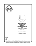
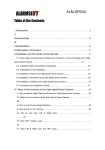
DF5 Series
Fixed-Mount
Dome
Installation/
Operation Manual
C1458M-D (6/98)
Pelco • 300 W. Pontiac Way, Clovis • CA 93612-5699 USA • Pelco Online @ http://www.pelco.com
In North America and Canada: Tel (800) 289-9100 or FAX (800) 289-9150 • DataFAX (800) 289-9108
International Customers: Tel (1-209) 292-1981 or FAX (1-209) 348-1120 • DataFAX (1-209) 292-0435
CONTENTS
Section
Page
1.0 GENERAL .................................................................................................. 5
1.1 IMPORTANT SAFEGUARDS AND WARNINGS ............................... 5
1.2 UNPACKING INSTRUCTIONS .......................................................... 6
1.3 RECOMMENDED TOOLS ................................................................. 7
2.0 DESCRIPTION .......................................................................................... 8
2.1 MODELS ............................................................................................ 8
3.0 INSTALLATION FOR IN-CEILING MODELS ............................................. 9
3.1 CEILING AND BACK BOX PREPARATION ...................................... 9
3.1.1 Hard Ceiling ............................................................................ 9
3.1.2 Suspended Ceiling .................................................................. 9
3.2 WIRING ............................................................................................ 11
3.3 BACK BOX INSTALLATION ............................................................. 11
3.4 CAMERA AND LENS INSTALLATION .............................................. 13
3.4.1 Camera and Lens Pre-Installed ............................................. 13
3.4.2 No Camera or Lens Installed ................................................. 13
3.4.3 Camera Pre-Installed Without Lens ....................................... 13
3.4.3.1 General Lens Information ........................................ 13
3.4.3.2 Lens Mounting ......................................................... 13
3.4.3.3 Auto-Iris Lenses ....................................................... 13
3.5 CAMERA WIRING ............................................................................ 15
3.6 CAMERA ADJUSTMENTS ............................................................... 15
3.6.1 Back-Focus Adjustment ......................................................... 15
3.6.2 Vertical Phase Adjustment ..................................................... 16
3.7 LOWER DOME INSTALLATION ....................................................... 17
4.0 INSTALLATION FOR PENDANT MODELS .............................................. 18
4.1 PENDANT-MOUNT INSTALLATION ................................................ 18
4.2 SURFACE-MOUNT INSTALLATION ................................................ 19
5.0 MAINTENANCE ........................................................................................ 20
5.1 DOME CLEANING ............................................................................ 20
5.2 SERVICE MANUAL .......................................................................... 20
6.0 SPECIFICATIONS .................................................................................... 21
7.0 WARRANTY AND RETURN INFORMATION ........................................... 24
2
Pelco Manual C1458M-D (6/98)
LIST OF ILLUSTRATIONS
Figure
1
2
3
4
5
6
7
8
9
10
11
Page
Back Box Parts .................................................................................. 6
Compass Tool ................................................................................... 10
Conduit Fitting Installation ................................................................ 10
Installing Back Box ........................................................................... 10
Fastening Back Box .......................................................................... 10
Tilt Table Assembly ........................................................................... 13
Location of Camera Parts and Controls ............................................ 14
Lower Dome Installation ................................................................... 17
Lower Dome Installation, Pendant Models ....................................... 18
Surface-Mount Installation ................................................................ 19
DF5 Series Dimension Drawing ........................................................ 23
LIST OF TABLES
Table
A
B
Page
Video Coaxial Cable Requirements .................................................. 12
24 VAC Wiring Distances .................................................................. 12
REVISION HISTORY
Pelco Manual C1458M-D (6/98)
Manual #
Date
Comments
C1458M
4/97
Original version.
C1458M-A
7/97
Rev. A. Added indoor pendant models.
C1458M-B
12/97
Added DF5C and DF5M pendant models. Added
outdoor pendant models. Removed column for 22gauge wire from Table B. Added dimensions for pendant
models to Figure 17.
C1458M-C
2/98
Deleted references to SD5-P, which is covered in
C1459M. Deleted exploded assembly diagrams, which
are included in C1458SM. Changed manual pagination.
C1458M-D
5/98
Revised model numbers. Revised camera installation
instructions. Removed all material relating to the DF5C
and DF5M models. Revised the procedures under
Section 3.7, Lower Dome Installation. Revised one
Note and deleted another under Section 4.1, PendantMount Installation. Added a Note in Section 4.2,
Surface-Mount Installation.
6/98
Revised Section 4.1 and Figures 9 and 11 because of
modification to top mount.
3
(This page intentionally left blank.)
4
Pelco Manual C1458M-D (6/98)
1.0 GENERAL
1.1 IMPORTANT SAFEGUARDS AND WARNINGS
Prior to installation and use of this product, the following WARNINGS should be
observed.
1.
Installation and servicing should only be done by qualified service personnel
and conform to all local codes.
2.
Unless the unit is specifically marked as a NEMA Type 3, 3R, 3S, 4, 4X, 6, or
6P enclosure, it is designed for indoor use only and it must not be installed
where exposed to rain and moisture.
3.
Only use replacement parts recommended by Pelco.
4.
After replacement/repair of this unit’s electrical components, conduct a resistance measurement between line and exposed parts to verify the exposed
parts have not been connected to line circuitry.
5.
The installation method and materials should be capable of supporting four
times the weight of the enclosure, pan/tilt, camera and lens combination.
The product and/or manual may bear the following marks:
This symbol indicates that dangerous voltage constituting a
risk of electric shock is present within this unit.
This symbol indicates that there are important operating and
maintenance instructions in the literature accompanying this
unit.
CAUTION:
RISK OF
ELECTRIC SHOCK.
DO NOT OPEN.
CAUTION:
TO REDUCE THE RISK OF ELECTRICAL SHOCK,
DO NOT REMOVE COVER. NO USERSERVICEABLE PARTS INSIDE. REFER SERVICING
TO QUALIFIED SERVICE PERSONNEL.
Please thoroughly familiarize yourself with the information
in this manual prior to installation and operation.
Pelco Manual C1458M-D (6/98)
5
1.2 UNPACKING INSTRUCTIONS
Unpack and inspect all parts carefully.
The DF5 shipping carton contains two boxes:
1 box
1 box
containing the back box
containing the trim ring and lower dome
Inspect your equipment to make sure all parts are present.
Back Box
1
1
1
1
Back box (includes camera and lens if specified with order)
Installation/Operation Manual (C1458M-D)
Tilt table assembly (models without camera)
Parts bag (refer to Figure 1)
1 Conduit fitting (in-ceiling models only)
1 Safety chain bracket (in-ceiling models only)
1 Lock nut (in-ceiling models only)
1 Compass tool (in-ceiling models only)
1 Flat washer (models without camera)
1 Split lock washer (models without camera)
1 Screw (models without camera)
Lower Dome
1
1
Acrylic lower dome with trim ring
Parts bag (pendant models only)
1 O-ring
1 O-ring lubricant
2 Screw, 6-32 x 5/16"
1 Tube of Loctite®
Be sure to save the shipping carton, boxes and inserts. They are the safest materials in which to make future shipments.
If an item appears to have been damaged in shipment, replace it properly in its box
and contact the factory at 1-800-289-9100 or 1-209-292-1981 for a replacement.
(International customers fax 1-209-348-1120 for authorization and instructions.)
If an item needs to be returned to the factory for repair, consult the WARRANTY
AND RETURN section of this manual for instructions.
COMPASS TOOL
SAFETY BRACKET
CONDUIT FITTING
& LOCK NUT
Figure 1. Back Box Parts
6
Pelco Manual C1458M-D (6/98)
1.3 RECOMMENDED TOOLS
Pelco does not supply basic tools needed for the installation process. The following
tools are recommended:
Pen or pencil (in-ceiling models only)
Drill with 3/32-inch drill bit (in-ceiling models only)
Saw to cut hole in ceiling (in-ceiling models only)
Small flat screwdriver
Medium Phillips screwdriver
Wire stripper
BNC crimp tool
Wire cutter
Coaxial cable stripper
Drill with hole saw (pendant surface-mount only)
Pelco Manual C1458M-D (6/98)
7
2.0 DESCRIPTION
DF5 Series domes are discreet surveillance domes that are designed for indoor or
outdoor use. Models include pendant and in-ceiling versions.
In-ceiling models have plenum-rated back boxes and can be installed in hard ceilings or standard 2' x 2' (6 x 61 cm) suspended ceilings.
Indoor pendant models come in light gray or black finish. Outdoor pendant models
are light gray only and include a heater that allows operation down to -60° F(-51° C).
Models with a camera include a 1/3-inch format, high-resolution color or monochrome camera.
2.1 MODELS
DF5CA-PG-02.3A
DF5 Series dome
C = Color camera
M = Monochrome camera
Blank = No camera
A = 24 VAC camera power
NTSC standard (color)
EIA standard (monochrome)
Blank = No camera
PB = Pendant, black
PG = Pendant, light gray
Blank = In-ceiling back box
0 = Smoked dome
(1/2 f-stop of light loss)
1 = Clear dome
2 = Chrome dome (2
f-stops of light loss)
3 = Gold dome (2 f-stops
of light loss)
E0 = Outdoor pendant
(includes heater and
sun shield), light gray,
smoked dome (1/2 f-stop
of light loss)
EI = Outdoor pendant
(includes heater and
sun shield), light gray,
clear dome
2.3 = 2.3 mm lens
2.8 = 2.8 mm lens
4 = 4 mm lens
8 = 8 mm lens
V2 = 2.5-6 mm varifocal lens
V3 = 3-8 mm varifocal lens
V35 = 3.5-8 mm varifocal lens
V5 = 5-40 mm varifocal lens
Blank = No lens
A = Auto iris
Blank = Manual iris
8
Pelco Manual C1458M-D (6/98)
3.0 INSTALLATION FOR IN-CEILING MODELS
3.1 CEILING AND BACK BOX PREPARATION
3.1.1 Hard Ceiling
CAUTION: Be careful not
to cut outside the line. If you
do, you may not be able to
install the back box. Also,
the trim ring may not cover
the hole.
1.
Locate the center point where you want to drill a hole in the ceiling.
2.
Drill a hole in the ceiling using a 3/32-inch drill bit.
3.
Remove the compass tool from the parts bag (refer to Figure 2). Press the
stud of the compass tool into the hole in the ceiling. Insert a pencil in the hole
in the other end of the compass and mark a circle on the ceiling.
4.
Carefully cut the circle out of the ceiling.
5.
Remove the conduit fitting, lock nut, and safety chain bracket from the parts
bag and attach them to the back box as shown in Figure 3.
Proceed to Section 3.2, WIRING.
3.1.2 Suspended Ceiling
CAUTION: The ceiling tile
must be capable of supporting 16 pounds (7.3 kg) of
weight. If the ceiling tile will
not support this weight, use
the optional SD5-P metal
panel.
1.
Remove the ceiling tile from the ceiling.
2.
Locate the center point to drill a hole in the tile.
3.
Drill a hole in the ceiling tile using a 3/32-inch drill bit.
4.
Remove the compass tool from the parts bag (refer to Figure 2). Press the
stud of the compass tool into the hole in the ceiling. Insert a pencil in the hole
in the other end of the compass and mark a circle on the ceiling.
CAUTION: Be careful not
to cut outside the line. If you
do, you may not be able to
install the back box. Also,
the trim ring may not cover
the hole.
5.
Carefully cut the circle out of the ceiling tile.
6.
Remove the conduit fitting, lock nut, and safety chain bracket from the parts
bag and attach them to the back box as shown in Figure 3.
7.
Refer to Figure 4. Compress the spring paddles on the back box with your
hands and push the back box through the hole in the ceiling tile. The spring
paddles will spring out when they clear the ceiling tile.
8.
Refer to Figure 5. Tighten the screws until the spring paddles hold the back
box firmly to the ceiling tile. You will hear a clicking noise when the screws are
tight. Do not install the ceiling tile in the ceiling yet.
Proceed to Section 3.2, WIRING.
Pelco Manual C1458M-D (6/98)
9
ATTACH SAFETY CHAIN HERE
Figure 2. Compass Tool
Figure 3. Conduit Fitting Installation
HARD CEILING
OR
CEILING TILE
Figure 4. Installing Back Box
10
Figure 5. Fastening Back Box
Pelco Manual C1458M-D (6/98)
3.2 WIRING
Bring wiring for the camera to the back box opening in the ceiling.
Refer to Table A for the type of video coaxial cable to use.
If the camera will be powered by 24 VAC, refer to Table B to determine the size of
wire to use.
If your dome is supplied with Pelco's CCC4000-2 or MCC5600-2 camera, it uses
24 VAC or 12 VDC. A safety ground terminal is provided on the camera. If you want
to connect the camera to ground (optional), bring a ground wire to the back box
opening.
Models with heaters require 24 VAC for the heater. The heater uses 60 watts of
power. If the camera uses 24 VAC, add the camera’s power to that of the heater
and refer to Table B to determine the size of wire to use.
Proceed to Section 3.3, BACK BOX INSTALLATION.
3.3 BACK BOX INSTALLATION
CAUTION: The ceiling
must be capable of supporting 16 pounds (7.3 kg) of
weight. If the ceiling will not
support this weight, provide
additional reinforcement.
Also, a suitable safety chain
must be attached to the
back box to support up to 16
pounds (7.3 kg) in the event
of a ceiling failure.
1.
Suspended Ceiling Only (for hard ceiling, go to step 2) - Install the ceiling
tile with the back box.
2.
Install a safety chain or cable (not supplied) that will support up to 16 pounds
(7.3 kg). Fasten one end to a support structure in the ceiling. Fasten the other
end to the safety chain bracket (refer to Figure 3) to prevent the back box from
falling.
3.
Bring the wiring into the back box through the conduit fitting. If the wiring is
inside flexible conduit, connect the conduit to the fitting on the back box.
4.
Hard Ceiling Only - Refer to Figure 4. Compress the spring paddles on the
back box with your hands and push the back box through the hole in the ceiling. The spring paddles will spring out when they clear the ceiling. Refer to
Figure 5. Tighten the screws until the spring paddles hold the back box firmly
to the ceiling. You will hear a clicking noise when the screws are tight.
Proceed to Section 3.4, CAMERA AND LENS INSTALLATION.
Pelco Manual C1458M-D (6/98)
11
Table A. Video Coaxial Cable Requirements
Cable Type*
Maximum Distance
RG59/U
RG6/U
RG11/U
750 ft (229 m)
1,000 ft (305 m)
1,500 ft (457 m)
* Minimum cable requirements:
75 ohms impedance
All-copper center conductor
All-copper braided shield with 95% braid coverage
Table B. 24 VAC Wiring Distances
The following are the recommended maximum distances for 24 VAC applications
and are calculated with a 10-percent voltage drop. (Ten percent is generally the
maximum allowable voltage drop for AC-powered devices.)
EXAMPLE: An enclosure that requires 80 vA and is installed 35 feet
(10 m) from the transformer would
require a minimum wire gauge of 20
Awg.
Wire Gauge
Total vA consumed
NOTE: Distances are calculated in
feet; values in parentheses are
meters.
12
18
16
14
12
10
10
283
(86)
451 716
(137) (218)
1142 1811 2880
(348) (551) (877)
20
141
(42)
225 358
(68) (109)
571 905 1440
(174) (275) (438)
30
94
(28)
150
(45)
238
(72)
380 603 960
(115) (183) (292)
40
70
(21)
112
(34)
179
(54)
285
(86)
452 720
(137) (219)
50
56
(17)
90
(27)
143
(43)
228
(69)
362 576
(110) (175)
60
47
(14)
75
(22)
119
(36)
190
(57)
301
(91)
480
(146)
70
40
(12)
64
(19)
102
(31)
163
(49)
258
(78)
411
(125)
80
35
(10)
56
(17)
89
(27)
142
(43)
226
(68)
360
(109)
90
31
(9)
50
(15)
79
(24)
126
(38)
201
(61)
320
(97)
100
28
(8)
45
(13)
71
(21)
114
(34)
181
(55)
288
(87)
110
25
(7)
41
(12)
65
(19)
103
(31)
164
(49)
261
(79)
120
23
(7)
37
(11)
59
(17)
95
(28)
150
(45)
240
(73)
130
21
(6)
34
(10)
55
(16)
87
(26)
139
(42)
221
(67)
140
20
(6)
32
(9)
51
(15)
81
(24)
129
(39)
205
(62)
150
18
(5)
30
(9)
47
(14)
76
(23)
120
(36)
192
(58)
160
17
(5)
28
(8)
44
(13)
71
(21)
113
(34)
180
(54)
170
16
(4)
26
(7)
42
(12)
67
(20)
106
(32)
169
(51)
180
15
(4)
25
(7)
39
(11)
63
(19)
100
(30)
160
(48)
190
14
(4)
23
(7)
37
(11)
60
(18)
95
(28)
151
(46)
200
14
(4)
22
(6)
35
(10)
57
(17)
90
(27)
144
(43)
Maximum distance from transformer to load
20
Pelco Manual C1458M-D (6/98)
3.4 CAMERA AND LENS INSTALLATION
3.4.1 Camera and Lens Pre-Installed
If your dome has a Pelco camera and lens already installed, proceed to Section
3.5, CAMERA WIRING.
3.4.2 No Camera or Lens Installed
If your dome does not have a camera or lens installed:
5
ATTACH TO
BACK BOX
BASE
PLATE
2
3
1.
Install the lens on the camera according to the camera and lens manufacturers' instructions.
2.
Refer to Figure 6. Attach the tilt table (1) and the support leg (2) to the base
plate of the back box with the 1/4-inch fender washer (3), split lock washer (4),
and nut (5) that are provided. Tighten the nut snugly, but leave it loose enough
so that you can still rotate the tilt table with your hand.
3.
Attach the camera to the tilt table with the 1/4-20 screw, split lock washer, and
flat washer that are supplied.
4
1
Figure 6. Tilt Table Assembly
Proceed to Section 3.5, CAMERA WIRING.
3.4.3 Camera Pre-Installed Without Lens
If your dome has a Pelco camera installed but no lens, install a lens on the camera.
3.4.3.1 General Lens Information
NOTE: Passive (DC-controlled)
auto-iris lenses are recommended
in outdoor applications to control
lighting changes and prevent picture smear.
NOTE: The CCC4000-2 and
MCC5600-2 cameras will not
support active (video controlled)
auto-iris lenses (having a built-in
electronic circuit for driving the iris).
Pelco's CCC4000-2 and MCC5600-2 cameras are equipped with a standard lens
mount and are factory adjusted to the CS-mount standard. Fixed iris, manual iris, or
passive (DC controlled) auto-iris lenses may be used. Passive (DC controlled) autoiris lenses require a standard 4-pin square connector (type D4-152N, not supplied)
that is standard on all Pelco lenses.
C-mount lenses are also compatible by using a 5-mm spacer, commonly referred to
as a C/CS-mount adapter.
3.4.3.2 Lens Mounting
Do not release the back-focus locking ring unnecessarily. Back-focus adjustment has been set at the factory to the standard CS-mount back-focus distance.
To mount a lens:
1.
Remove the black protection cover from the CS-mounting ring.
2.
To install a C-mount lens, mount a C/CS-mount adapter between lens and
camera.
3.
Screw the lens on the camera. Be careful to prevent dust from entering the
space between the lens and the CCD element. If necessary, use clean, compressed air to remove any foreign matter.
4.
When using a passive (DC-controlled) auto-iris lens, connect the iris cable to
the iris connector on the back of the camera. Refer to Figure 7. See also Section 3.4.3.3, AUTO IRIS-LENSES.
Proceed to Section 3.5, CAMERA WIRING.
3.4.3.3 Auto-Iris Lenses
Passive auto-iris lenses are DC-controlled via the 4-pin iris drive connector (type
D4-152N) located on the back of the camera (refer Figure 7). When an auto-iris lens
is used the electronic shutter speed is fixed at 1/60th of a second.
Refer to Figure 7 for the pin connections for the iris drive connector.
Pelco Manual C1458M-D (6/98)
13
FRONT VIEW
REAR VIEW
BACK-FOCUS
LOCKING RING
POWER
CONNECTOR
IRIS
CONNECTOR
CS-MOUNT RING
1/3" CCD
ELEMENT
CAMERA MOUNT
(1/4-20 UNC)
IRIS CONNECTOR PINOUTS
2
3
1
V-PHASE
ADJUSTMENT
POWER CONNECTOR PINOUTS
AC
DC–
4
VIDEO OUTPUT
(BNC)
AC
DC+
GND
PIN 1 = CONTROL COIL + (DAMPING COIL –)
PIN 2 = CONTROL COIL – (DAMPING COIL +)
PIN 3 = DRIVE COIL +
PIN 4 = DRIVE COIL –
Figure 7. Location of Camera Parts and Controls
14
Pelco Manual C1458M-D (6/98)
3.5 CAMERA WIRING
1.
Connect power and video wiring to the camera.
For models with heaters, attach 24 VAC power to the terminal block inside the
back box. If the camera uses 24 VAC, connect the spade lugs on the two
loose wires inside the back box to the 24 VAC input of the camera. If you do
not use the wires, isolate them from touching anything.
If your dome has a Pelco CCC4000-2 or MCC5600-2 camera, connect the
power and video wiring to the camera. Refer to Figure 7. A safety ground
terminal (
) is provided on the connector block to connect the camera to
ground potential. Maximum voltage between the supply inputs and the safety
ground must be less than 50 volts. Camera electronics are galvanically insulated from the camera supply, which protects a system with more than one
camera from ground loop problems. The power connector block can be removed from the camera to ease mounting and/or installation.
If your dome has a different type of camera, connect the power and video
wiring to the camera according to the camera manufacturer's instructions.
If you are using AC power and are wiring more than one camera to the same
transformer, connect one side of the transformer to the same terminal on all
cameras, and connect the other side of the transformer to the remaining terminal on all cameras. Failure to connect all of the cameras the same will cause
the cameras to be out of phase with each other and may produce what appears to be vertical roll when switching between cameras.
2.
Make sure the other end of the video cable is connected to a monitor or video
equipment that goes to a monitor. Turn on power to the system. Observe the
monitor and adjust the tilt table to place the camera in the desired position.
Tighten the two nuts on the tilt table. It may be necessary to remove or tilt the
camera to reach the mounting nut in the top of the back box.
Proceed to Section 3.6, CAMERA ADJUSTMENTS.
3.6 CAMERA ADJUSTMENTS
Adjust the camera and lens according to the manufacturers’ instructions.
The remainder of this section applies to Pelco’s CCC4000-2 and MCC5600-2 cameras. Proceed to Section 3.7, LOWER DOME INSTALLATION, if you do not have
one of these cameras.
1.
Aim the camera and focus the lens to the object or area to be observed.
2.
If a manual-iris lens is used, adjust the iris for the best picture quality. The
largest aperture gives the best light sensitivity, the smallest aperture the greatest
depth of field.
3.6.1 Back-Focus Adjustment
NOTE: The iris cable of a (passive) auto-iris lens prevents the
lens being rotated more than
180°. In this case, disconnect the
iris cable, rotate the lens a full
turn, reconnect the iris cable, and
continue the adjustment.
Do not release the back-focus locking ring unnecessarily. Back-focus adjustment has been set at the factory to the standard CS-mount back-focus distance.
NOTE: When adjusting backfocus with an auto-iris lens, the
iris cable must be plugged into
the iris drive connector; otherwise, the iris will not open.
To change back-focus the lens must be mounted onto the camera.
Pelco Manual C1458M-D (6/98)
Back-focus is defined as the distance between the lens optics and the camera’s
CCD sensing element.
A camera that gives an unsharp picture using a particular lens may require backfocus adjustment.
To change the back-focus:
1.
With the camera operating, position the camera to view the intended object.
15
2.
Set the focus ring, if present, to infinity.
3.
Set the lens iris to its widest usable opening. Use a neutral density filter with
auto-iris lenses in outdoor or bright light settings to ensure maximum iris opening
during back-focus adjustment. When a neutral density filter is not available,
point the camera to a relatively dark area to obtain the greatest iris opening.
4.
Adjust the back-focus:
a.
Turn the back-focus locking ring counterclockwise to loosen the CS-mount
ring.
b.
Adjust the lens and the CS-mount ring together until picture is sharpest.
c.
Hold the lens and CS-mount ring in place and turn the back-focus locking
ring clockwise to tighten.
3.6.2 Vertical Phase Adjustment
Vertical phase (V-phase) adjustment is unnecessary when using AC power with a
single camera.
When powering more than one camera with AC, phase differences may occur as a
result of being connected to different power groups. These phase differences become apparent as a brief rolling of the picture each time cameras are switched,
known as vertical roll. Vertical roll can be corrected by synchronizing the cameras
with the V-phase adjustment.
Generally, it is necessary to have two people in communication when cameras are
synchronized: one person at the camera to be synchronized and another person at
the monitor to observe the vertical “roll” and the effect of any adjustments made at
the camera.
To adjust the vertical phase:
1.
Choose a camera to which all of the other cameras will be synchronized. By
going through the available cameras it can be determined the best camera to
which the others should be synchronized.
2.
Select a second camera that is out of synchronization with the first camera.
3.
Switch the cameras back and forth, observing the “roll” between the cameras
when they are switched.
4.
If “roll” is present, adjust the vertical phase (refer to Figure 7 for the location of
the V-phase adjustment).
CCC4000-2 Camera: Press the V–phase button with a pointed object such as
a pencil, then switch cameras again and observe the roll. Each press of the
button will shift the phase 60°.
MCC5600-2 Camera: Adjust the potentiometer with a small Phillips screwdriver. V-phase is adjustable between 0° to 220°.
5.
Repeat this process as many times as necessary and for each of the other
cameras in the system.
Proceed to Section 3.7, LOWER DOME INSTALLATION.
16
Pelco Manual C1458M-D (6/98)
3.7 LOWER DOME INSTALLATION
1.
Snap the clip on the trim ring leash into the hole on the lip of the back box next
to one of the mounting screws.
2.
If you have a clear dome, position the inner dome liner so its slot aligns with
the camera lens.
3.
Line up the snaps on the trim ring with the mounting screws on the back box.
Snap the trim ring into place on the plastic snap washers on the mounting
screws.
4.
If there are blemishes on the dome, rotate it for a clearer picture.
Figure 8. Lower Dome Installation
Pelco Manual C1458M-D (6/98)
17
4.0 INSTALLATION FOR PENDANT MODELS
4.1 PENDANT-MOUNT INSTALLATION
NOTE: If outdoors, apply Duct Seal
inside the pipe portion of the back box
to prevent moisture or cold air inside
the mount from entering the unit and
causing condensation on the dome.
Make sure no moisture has condensed inside the unit before installing the lower dome. Duct Seal can
be purchased through local electrical
supply houses.
1.
Install the pendant dome mount. Refer to the instructions supplied with the
mount. If the mount is outdoors, make sure it is properly sealed to keep moisture out.
2.
Bring the wiring for the dome through the mount. Refer to Section 3.2, WIRING.
3.
Screw the back box to the mount and bring the wiring into the back box. If
outdoors, apply the provided pipe sealant to the threads on the back box.
4.
Refer to Sections 3.4 through 3.6 for camera and lens installation, wiring, and
adjustment procedures.
5.
Remove the O-ring and O-ring lubricant from the parts bag. Apply lubricant to
the O-ring. Install the O-ring in the groove on the trim ring of the lower dome.
6.
Refer to Figure 9. Hanging down from the back box is a short cable (the trim
ring leash). Hold up the lower dome near the back box so that the trim ring
leash touches the lower dome. Line up the two screw holes in the trim ring of
the lower dome with the two screw holes in the back box. Place a finger on the
edge of the trim ring where the leash touches the lower dome.
LEASH
SCREW HOLES
(FRONT & BACK)
ATTACH LEASH
TO NEAREST
RETAINER
SCREW
Figure 9. Lower Dome Installation, Pendant Models
18
Pelco Manual C1458M-D (6/98)
7.
Look inside the lower dome and note which of the six retainer screws is closest to your finger. Remove this screw and attach the trim ring leash to the
screw. Reinstall the screw securely and make sure the leash will hold the
lower dome.
8.
If you are installing an outdoor model, plug the two-pin heater connection in
the lower dome into the mating connector in the back box.
9.
Remove the two screws and the tube of Loctite® from the parts bag. Apply a
drop of Loctite® to each screw.
10. Push the lower dome inside the back box, line up the screw holes, and install
the two screws.
4.2 SURFACE-MOUNT INSTALLATION
NOTE: For hard ceilings, such as
concrete, where the wiring must be
installed in surface-mounted conduit,
use the optional BB5-PCA-BK (black)
or BB5-PCA-GY (gray) Pendant Conduit Adapter.
1.
Use a hole saw to drill a hole in the ceiling where you want to hang the pendant dome.
2.
Bring the wiring for the dome to the opening. Refer to Section 3.2, WIRING.
3.
Refer to Figure 10. Remove the gasket (item 1) and the top mount (item 2)
from the back box (item 3) by taking out the three screws and lock washers
(items 4 and 5).
4.
Attach the back box to the ceiling using #8 hardware (not supplied). Reattach
the cable (trim ring leash) that was attached to one of the screws you removed
in step 3.
5.
Refer to Sections 3.4 through 3.6 for camera and lens installation, wiring, and
adjustment procedures.
6.
Remove the O-ring and O-ring lubricant from the parts bag. Apply lubricant to
the O-ring. Install the O-ring in the groove on the trim ring of the lower dome.
7.
Refer to Figure 9. Hanging down from the back box is a short cable (the trim
ring leash). Hold up the lower dome near the back box so that the trim ring
leash touches the lower dome. Line up the two screw holes in the trim ring of
the lower dome with the two screw holes in the back box. Place a finger on the
edge of the trim ring where the leash touches the lower dome.
8.
Look inside the lower dome and note which of the six retainer screws is closest to your finger. Remove this screw and attach the trim ring leash to the
screw. Reinstall the screw securely and make sure the leash will hold the
lower dome.
9.
Remove the two screws and the tube of Loctite® from the parts bag. Apply a
drop of Loctite® to each screw.
10. Push the lower dome inside the back box, line up the screw holes, and install
the two screws.
1
3
2
4
5
Figure 10. Surface-Mount Installation
Pelco Manual C1458M-D (6/98)
19
5.0 MAINTENANCE
5.1 DOME CLEANING
Clean the acrylic dome as necessary to maintain a clear picture. Be careful not the
scratch the surfaces of the dome.
Exterior Surface - Clean the dome’s exterior surface with a nonabrasive cleaning
cloth and cleaning agent that is safe for acrylic plastic. Either liquid or spray cleaner/
wax suitable for fine furniture is acceptable.
Interior Surface (Except Chrome or Gold) - Clean the same as the exterior surface.
Interior Surface (Chrome or Gold) - The inside surface of a chrome or gold dome
is easily scratched. Use the following precautions to maintain the dome’s surface.
A.
Always handle the dome from the outside of its circular flange.
B.
Never touch the coated inside surface. The acid in your fingerprints will eventually etch the coating if the fingerprints are not carefully removed according
to the recommended cleaning procedure in item E.
C.
If dust or other contaminants accumulate on the dome’s interior, remove the
debris with compressed air. Compressed air cans are available from photographic equipment or electronic supply dealers.
D.
If heavy residue accumulates and cannot be removed with air pressure, rinse
with water and immediately dry with air pressure so that water spots will not
remain. Avoid wiping the coated surface with direct hand pressure - it will easily
abrade unless extreme care is taken. Once scratched, the dome cannot be
recoated.
E.
If internal wiping is necessary, avoid hand rubbing. Instead, make a wick as
follows:
Use a very soft paper towel. Roll a section into a tightly wound tube. Tear the
tube in half, and wet the fuzzy end of the wick with a solution of isopropyl
alcohol diluted with water. Hold the dome with its opening facing downward
and wipe the interior of the dome with the wet end of the wick. Use a circular
motion, starting from the outside and spiraling into the center. Use a new wick
for each two passes over the dome.
5.2 SERVICE MANUAL
If you need to service the unit, obtain a service manual in one of the following ways:
20
•
Go to Pelco’s web site at ftp://www.pelco.com and find service manual
C1458SM.
•
Call Pelco’s DataFax service at 1-209-292-0435 and request document 214588.
•
Contact Pelco’s Literature Department and request service manual C1458SM.
Pelco Manual C1458M-D (6/98)
6.0 SPECIFICATIONS
MECHANICAL
Construction
Back Box:
Mounting
Bracket:
Dimensions:
Aluminum
Steel
See Figure 11
GENERAL
Environment:
Indoor and outdoor
Operating
Temperature
Indoor:
32° to 120°F (0° to 49°C)
Outdoor:
-10° to 120°F (-23° to 49°C)
Weight
Unit
Shipping
In-Ceiling
(without camera): 2.80 lb (1.27 kg)
6.0 lb (2.72 kg)
Pendant
(without camera): 4.25 lb (1.93 kg)
8.0 lb (3.63 kg)
Add 1.50 (0.68 kg) for heater and sun shield
CAMERA
DF5 Models Without Camera
Maximum Camera
and Lens Size:
(with camera positioned at 90° from horizontal)
6.0” L x 2.75” W x 2.75” H (15.24 x 6.99 x 6.99 cm)
CCC4000-2 Color (NTSC) Camera
CCD Sensor:
Pixels:
Sensing Area:
Sync System:
Horizontal
Resolution:
Iris Control:
Lens Mount:
Light Sensitivity:
Electronic
Shutter Speed:
Signal-to-Noise
Ratio:
Gain Control:
Vertical Phase
Adjustment:
Power
Requirements:
Video Output:
Lens Jack:
Power
Consumption:
Operating
Temperature:
Humidity:
Construction:
Mounting
Threads:
Dimensions:
Weight:
Pelco Manual C1458M-D (6/98)
Color 1/3" interline transfer
512 x 492 (horizontal x vertical)
4.7 mm x 3.5 mm (3/16" x 1/8")
Free running/line lock (when AC powered)
400 TV lines
Electronic/passive
CS
3.5 lux (≥ 50 ire/-6 dB) at f1.2
1/60 sec–1/50,000 sec
> 50 dB
Automatic
60° increments
12-27.6 VAC, 10.8-39 VDC
CVBS, 1 Vp-p/75 ohms
4-pin connector (type D4-152N)
2.7 watts (max.) (camera only)
14° to 122°F (-10° to 50°C)
20% to 95% relative humidity
Conductive-coated ABS
1/4-20 UNC
2.75" W x 2.88" H x 2.38" D
(70 mm x 73 mm x 60 mm)
0.45 lb (200 g) (without lens)
21
MCC5600-2 Monochrome Camera
CCD Sensor:
Pixels:
Sensing Area:
Sync System:
Horizontal
Resolution:
Iris Control:
Lens Mount:
Minimum
Illumination:
Electronic
Shutter Speed:
Signal to
Noise Ratio:
Gain Control:
Vertical Phase
Adjustment:
Power
Requirements:
Video Output:
Lens Jack:
Power
Consumption
(camera only):
Operating
Temperature:
Humidity:
Storage
Temperature:
Mounting Threads:
1/3" interline transfer
768 x 492 (horizontal x vertical)
4.7 mm x 3.5 mm (3/16" x 1/8")
Free running/line lock (when AC powered)
560 TV lines
Electronic/passive
CS
<0.1 lux at f1.2
1/60–1/100,000 sec
> 50 dB
Automatic
0° to 220°
12-28 VAC, 10.8-39 VDC
CVBS, 1 Vp-p/75 ohms
4-pin connector (type D4-152N)
2.5 watts (max.)
-4° to 131°F (-20° to 55°C)
20% to 90% relative humidity
-13° to 158°F (-25° to 70°C)
1/4-20 UNC
Dimensions:
2.75" W x 2.88" H x 2.38" D (70 mm x 73 mm x 60 mm)
Weight
(without lens):
0.36 lb (163 g)
(Design and product specifications subject to change without notice.)
22
Pelco Manual C1458M-D (6/98)
IN-CEILING DOME
7.25 (18.13)
PENDANT DOME
TOP PORTION OF BACK BOX
IS REMOVABLE FOR SURFACE
MOUNT APPLICATIONS
6.60 (16.76)
DOME IS SECURED
TO CEILING BY
MOUNTING BRACKET
8.52
(21.64)
5.25
(13.34)
6.75
(17.15)
10.90
(27.69)
5.83
(14.80)
3.25
(8.26)
5.90 (14.99)
5.90
(14.99)
8.25 (20.96)
NOTE: VALUES IN PARENTHESES ARE CENTIMETERS; ALL OTHERS ARE INCHES
Figure 11. DF5 Series Dimension Drawing
Pelco Manual C1458M-D (6/98)
23
7.0 WARRANTY AND RETURN INFORMATION
WARRANTY
Pelco will repair or replace, without charge, any merchandise proved defective in
material or workmanship for a period of one year after the date of shipment. Exceptions to this warranty are as noted below:
•
•
•
•
•
•
Three years on Genex™ Series multiplexers.
Two years on all standard motorized and fixed focal length lenses.
Two years on Legacy®, Intercept®, PV1000 Series, CM6700/CM8500/CM9500/
CM9750/CM9760 Matrix, Spectra™, DF5 Series and DF8 Fixed Dome products.
Two years on WW5700 series window wiper (excluding wiper blades).
Two years on cameras.
Six months on all pan and tilts, scanners or preset lenses used in continuous
motion applications (that is, preset scan, tour and auto scan modes).
Pelco will warranty all replacement parts and repairs for 90 days from the date of
Pelco shipment. All goods requiring warranty repair shall be sent freight prepaid to
Pelco, Clovis, California. Repairs made necessary by reason of misuse, alteration,
normal wear, or accident are not covered under this warranty.
Pelco assumes no risk and shall be subject to no liability for damages or loss resulting from the specific use or application made of the Products. Pelco’s liability for
any claim, whether based on breach of contract, negligence, infringement of any
rights of any party or product liability, relating to the Products shall not exceed the
price paid by the Dealer to Pelco for such Products. In no event will Pelco be liable
for any special, incidental or consequential damages (including loss of use, loss of
profit and claims of third parties) however caused, whether by the negligence of
Pelco or otherwise.
The above warranty provides the Dealer with specific legal rights. The Dealer may
also have additional rights, which are subject to variation from state to state.
If a warranty repair is required, the Dealer must contact Pelco at (800) 289-9100 or
(209) 292-1981 to obtain a Repair Authorization number (RA), and provide the
following information:
1.
2.
3.
Model and serial number
Date of shipment, P.O. number, Sales Order number, or Pelco invoice number
Details of the defect or problem
If there is a dispute regarding the warranty of a product which does not fall under
the warranty conditions stated above, please include a written explanation with the
product when returned.
Ship freight prepaid to:
Pelco
300 West Pontiac Way
Clovis, CA 93612-5699
Method of return shipment shall be the same or equal to the method by which the
item was received by Pelco.
RETURNS
In order to expedite parts returned to the factory for repair or credit, please call the
factory at (800) 289-9100 or (209) 292-1981 to obtain an authorization number (CA
number if returned for credit, and RA number if returned for repair). Goods returned
for repair or credit should be clearly identified with the assigned CA/RA number and
freight should be prepaid. All merchandise returned for credit may be subject to a
20% restocking and refurbishing charge.
® Pelco and the Pelco logo are registered
trademarks of Pelco.
© Copyright 1998, Pelco. All rights
reserved.
24
Ship freight prepaid to:
Pelco
300 West Pontiac Way
Clovis, CA 93612-5699
Pelco Manual C1458M-D (6/98)