1
CBF4 Installation manual
HSAJET CBF4 installation manual
About this document
Users of this manual
This manual is designed to help the reader to install and operate the HSAJET Controller Board CBF4
(hereafter: CBF). It assumes that the reader has a fundamental understanding of basic computer
knowledge.
Notice:It is possible to install several CBF in one computer and use each board
separately (multiple time zones - with separate sensors / encoders) from the same
software. Running with multiple time zones is covered in a separate document. Please
inquire if you need this)
Related documents
In addition to this manual, you are also suggested to read the following manuals:
•
CB Board / INKdraw quick start: from installation to first printed message.
•
INKdraw reference manual: complete guide to INKdraw.
•
CB Board communication reference: network commands for remote control.
•
CB Board technical reference / service manual. Should be used under guidance from HSA Systems
only.
Version: 2010-12-16
Page 2 of 22
HSAJET CBF4 installation manual
Product Introduction
Product description
•
Controller for HP thermal inkjet heads
•
Up to 210 x 2700 mm print area (each board 50 x 2700 mm print area)
•
Network control
•
Multiple board synchronization possible
•
Multiple sensors possible
•
Real-time print of variable data and database content
The HSAjet CBF is a PCI-based controller board use to provide real-time control of print data for HP and
Xaar based printers.
Order codes
CBF-HP4
Controller Board for HP F-type printheads
Prescribed use
The CBF is designed to control up to 4 HP pens each, in any configuration of heads. It should be installed in
a PC with PCI-bus with Windows operating system (2000, XP). One slot is required for the CBF, additional
slots may be required for external connectors.
It is not possible to use PCI-Express connector for the HSAJET CBF.
You must use the PCI 32 bit connector(s).
Version: 2010-12-16
Page 3 of 22
HSAJET CBF4 installation manual
Installation procedure
For a successful installation you should carry out the following steps, each step is detailed in the following
pages
•
Install CBF board(s) in the computer.
•
Install device driver and software packages.
•
Setup and install print heads on conveyor – see separate document for relevant printer model.
Installation of print heads is not covered in this manual.
•
Connect cables to printers.
•
Verify installation
•
Carry out a purge on the printer.
•
Adjust parameters to get a perfect print. This is covered in other documentation.
When you have successfully purged your print head from the software, you are ready to create your first
message. This step is covered in CBF board quickstart or INKdraw manual.
Version: 2010-12-16
Page 4 of 22
HSAJET CBF4 installation manual
Safety instructions
This product, like all microcontroller products, uses semiconductors that can be
damaged by electrostatic discharge (ESD). When handling, care must be taken so that
the devices are not damaged.
Damage due to inappropriate handling is not covered by the warranty.
The following precautions must be taken:
•
Do not open the protective conductive packaging until you have read the following, and are at an
approved anti-static work station.
•
Use a conductive wrist strap attached to a good earth ground.
•
Always discharge yourself by touching a grounded bare metal surface or approved anti-static mat
before picking up an ESD - sensitive electronic component.
•
Use an approved anti-static mat to cover your work surface.
External devices:
This product interfaces with external devices like encoders, sensors, lamps and power supply’s. Make sure
that the voltage and power requirements of the external equipment is within specifications of the product.
Damage due to connections of faulty or wrong external equipment is not covered by the warranty.
Make absolutely sure that everything you connect has been wired correctly according to specifications.
Please see and understand wiring diagrams before you solder any connectors. Failure to wire connectors
correctly may result in damages to the product.
Installation environment
Environment
Installation area
Ambient temperature
Humidity
Surrounding Area
Version: 2010-12-16
Condition
Indoors
10 - 40 degrees C
95% RH or less, no condensation
Install in an area free from
• Oil mist and dust
• metal shavings or other foreign materials
• radioactive materials
• combustible materials
• hamful gases and liquids
• chlorides
• direct sunlight
• open flames
Page 5 of 22
HSAJET CBF4 installation manual
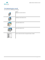
Terminologies used
This manual uses the following terminlogies
HPHF1
Single pen HP head with fuse
HPHF2
Double pen HP head with fuse
HPHF3
3 pen HP head with fuse
HPHF4
4 pen HP head with fuse
HPHF Distributor box
Use to connect more than one physical head to the CBF.
Version: 2010-12-16
Page 6 of 22
HSAJET CBF4 installation manual
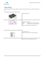
Unpacking
Unpack the CBF board with care. Carefully compare the content against the items covered by the packing
list.
The following components are always included:
CBF4 controller board
CD with manuals, software and driver
On the CD you will find
INKdraw
Design software for printed images
Driver
For Windows to talk to the PCI board
Mount kit (connectors for wiring of sensors)
The following parts are optional and included if ordered:
HPHF distributor box
Used to connect more than one physical head.
OPT-mntkit-ENC/RSR232
Bracket with encoder and RS232 connector.
Version: 2010-12-16
Page 7 of 22
HSAJET CBF4 installation manual
Installation of a single CBF4
Installing a single CBF board in a PC allows you to operate one of the following printer setups:
Number of pens
1, 2, 3 or 4 in a single head
Notice
Connects directly to back of CBF
1+1
1+1+1
1+1+1+1
2+1
2+2
3+1
Connects using a HPHF distributor box connected to
the back of the CBF
The installation requires one or two free slots in your PC.
Installation procedure
Caution: make sure you disconnect power completely before you start this procedure !
Serious damage to health and equipment may occur if you operate inside a PC with
power on.
•
Remove the PC chassis cover
•
Unpack the CBF board and confirm all jumpers are set correctly (see below)
•
Remove the bracket opposite the PCI slot that you intend to use. Keep the screw for later use.
•
Locate the gold fingers of the CBF over the PCI slot and press firmly down until the card is
completely seated in the slot. The gold fingers should not be visible at this point. If too much force
is needed look for any obstacles which prevents the proper seating of the CBF.
•
Secure the card to the chassis with the screw you removed earlier.
•
The CBF needs power supply in form of a standard internal PATA power connecter (IDE Big 4-pin
power connector). If necessary, use a Y-split cable from a hard drive.
Make sure that your PC has sufficient power to drive the print heads.
At least 10A per card you install (in 12V) should be available from the power supply.
Version: 2010-12-16
Page 8 of 22
HSAJET CBF4 installation manual
Optional steps:
• Connect the cable from the encoder bracket to the appropriate connector labeled "Encoder".
Connector fits one way only. Make sure it is all the way in.
Encoder bracket is mounted with a FEMALE SUBD 9 connector.
•
Connect the cable from the serial connection bracket to the appropriate connector labeled
"RS232 #1" Notice that "RS232#0" is NOT being used for external communication.
RS232 bracket is mounted with a MALE SUBD 9 connector
•
Either remove an additional filler bracket from the PC and install the ENC / RS232 bracket here, OR
mount connectors directly in PC chassis without the bracket.
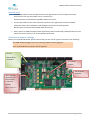
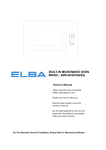
Overview of jumper settings
Before you install the CBF board, please confirm that you have set the jumpers correctly as per following:
CAUTION: Serious damage can occur if you set jumpers in the wrong place.
Users should ONLY move jumpers K8 through K13
K8..K13
Master/Slave
see below
JP3: NEVER
connect
JP1: 1-2 for HP
(printing or ink
low on OUT2);
2-3 for Xaar
(lowink)
JP6: MUST be
mounted
JP4-7: set to 1-2
Version: 2010-12-16
Page 9 of 22
HSAJET CBF4 installation manual
Jumpers K8..K13
Jumpers K8..K13 determine if the card is MASTER or SLAVE. The definition of these is:
MASTER:
Receive signals (SENSOR / ENCODER) from OUTSIDE
SLAVE:
Receive signals from a MASTER card through K1 connector
You only need to set to slave if you install multiple boards in a PC.
Set to 2-3 for MASTER (towards connectors K1/K2), and 1-2 for SLAVE (towards PCI contacts)
K8
Not used
K9
Sensor
Version: 2010-12-16
K10
Encoder A
K11
Encoder B
K12
Input 1
K13
Input 2
Page 10 of 22
HSAJET CBF4 installation manual
Check list CBF installation
Before you move on, please check and confirm
You have verified that all jumpers are set correctly
CB Board is firmly inserted and SECURED with a screw in the slot
CB Board has an active PATA power connector firmly attached (like a hard drive)
Encoder connector is mounted correctly if used, and firmly secured
RS232 connector is mounted correctly if used, and firmly secured
All connectors are labelled according to use. This will prevent incorrect connections
Version: 2010-12-16
Page 11 of 22
HSAJET CBF4 installation manual
Software installation
Before you can use your system you have to install driver and software.
Driver installation
First time you start your Windows machine after installing the CBF, Windows may report that a new PCI
device has been found. Just select "Cancel" to this.
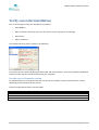
To install the driver open your file manager and browse the CD supplied with your system.
Locate the "Driver directory" on your CD
and execute the "Install" file
Click "Install"
The installation takes about 1 second
Software installation
Once you have installed the driver, you should install OBJ INKdraw
The installation file will be in the format inkinstall_{version}_{subversion}
From there, follow the prompts on screen. Default installation path is c:\{program files}\obj inkdraw
Version: 2010-12-16
Page 12 of 22
HSAJET CBF4 installation manual
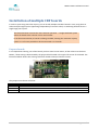
Connect cables
The installation of cables depends on the number of physical print heads you have. If you are using a single
head it attaches directly to the controller board. With multiple heads, you have to use a distributor box.
In the illustrations below an encoder is shown. The encoder is optional but strongly
recommended.
DO NOT connect any cables to the controller board(s) while the PC is turned on. You risk
damaging your PC and/or controller board(s).
•
•
•
•
•
•
•
•
Version: 2010-12-16
Head (1..4 pens) connects directly to back
of board
Sensor connects to back of board
Optional encoder connects to ENC
connector (FEMALE)
Optional Serial RS232 connection connects
to MALE connector above encoder.
Heads (maximum 4 pens in total) connects
via distributor box. Please refer to table
printed on distributor box.
Sensor connects to back of board
Optional encoder connects to ENC
connector (FEMALE)
Optional Serial RS232 connection connects
to MALE connector above encoder.
Page 13 of 22
HSAJET CBF4 installation manual
Verify succesful installation
You are now ready to verify your installation of products
•
Start INKdraw
•
Open a new file, choose HP type. You do not have to put anything in the message
•
press F9 key
•
Select "Firmware"
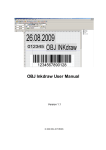
You should now see a picture similar to the following:
If you have version numbers displayed for both FPGA and microprocessor, you have succesfully established
communication with the controller board from your computer.
Use the correct firmware version
For optimal function it is important that you use the correct firmware / FPGA / microprocessor versions
depending on the software version you use.
Please see table below (status as of Nov 2010):
Status
Release version
Beta version
Version: 2010-12-16
Version
1.12.x
1.13.x
FPGA
MicroProcessor
2.1.9
1.2.11 / 1.3.23*)
2.1.9
1.2.11 / 1.3.23*)
*) 1.3.23 allows adjustment of serial speed. This version is in beta.
Page 14 of 22
HSAJET CBF4 installation manual
Check connection to heads by doing a purge
Finally you should test if you can do a purge from the software.
This serves two purposes:
•
To make sure that communication from the board to the print head is working
•
To identify where each print head and pen is connected. Doing this will make it simpler to create
messages, especially if you have a complex setup.
To purge all pens
• Insert a cartridge into all pen stalls as indicated above. Please make sure the cartridge is in working
condition and you have a media (paper etc) in front of the heads.
•
Select the Purge tab from the parameter menu [F9]
•
First purge each individual pen. The number of buttons available depends on the number of boards
installed. You will have 4 per board.
•
You should see a ½” full area covered by the cartridge.
•
Next, try to purge each board. The number of buttons available depends on the number of boards
you have installed.
•
This way you can identify INKdraws numbering of the boards if you have multiple boards installed.
Please take notice of this numbering - it is a good idea to put a small number on each head.
If you were able to purge all cartridges, and successfully tested all boards in TestIO
menu, you have a working installation. All you need to do now is to create a message
and adjust settings.
Version: 2010-12-16
Page 15 of 22
HSAJET CBF4 installation manual
Installation of multiple CBF boards
In order to print using more than 4 pens, you can install multiple controller boards in a PC, using them as
either multiple single systems (operating independently from each other) or combining the boards into a
single large print system.
This documentation assumes the most common operation – a single combined system
where the boards have common sensor and encoder.
In the illustrations below, 4 boards are being installed, showing the maximum capacity
system. It is of course possible to do the same with 2 or 3 boards.
Prepare boards
In a multiple board setting, one of the boards you have must be the master, all the others must be slave.
Master / Slave setting is determined by the jumper block located in the upper left corner of the board. The
illustration below shows slave setting. Default for boards when purchased is master.
The jumpers must be set as follows:
Status
Master
Slave
K8
Not used
2-3
1-2
Version: 2010-12-16
K9
Sensor
2-3
1-2
K10
Encoder A
2-3
1-2
K11
Encoder B
2-3
1-2
K12
Input 1
2-3
1-2
K13
Input 2
2-3
1-2
Page 16 of 22
HSAJET CBF4 installation manual
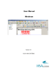
Insert boards in computer
In the PC you have selected for the installation, you should determine which PCI slot is the primary. This is
usually printed on the motherboard directly. Look for “PCI-1” or similar. The master card should be in this
first slot.
Now insert all boards into the PC. Make sure they are fitted all the way in.
INCORRECT. NOT FULLY INSERTED
CORRECT. ALL THE WAY IN SOCKET
Connect power connectors
After installation make sure the power connectors are connected to the boards. Each board needs a
connector. The order is indifferent.
Version: 2010-12-16
Page 17 of 22
HSAJET CBF4 installation manual
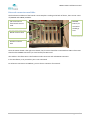
Connect boards and external connectors
Final step inside the PC is to connect the boards via a link cable. The cable is a 10-pin straight through cable
from one board to the next. If not supplied, you can make your own using a simple flat cable 10 pin (5x2)
socket.
In the illustration below, the additional bracket holding the encoder and RS232 socket has also been
connected.
Please notice how encoder and RS232 connects to the MASTER board. The other boards
receive encoder signals from the master board.
In the PC used here, the first PCI slot is at the bottom in the image. In other PCs the first
PCI slot may be closet to the processor. Please consult your motherboard
documentation.
Version: 2010-12-16
Page 18 of 22
HSAJET CBF4 installation manual
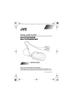
External connectors available
The hardware installation of the boards is now complete. Looking at the back of the PC, there is now 4 sets
of (SUBD25 and SUBD9) available.
I/O connectors on
slave boards are not
used.
MASTER
board. I/O
connector
should go
here.
RS232 connects here
Encoder connects
here
Since the master board is the right-most board, the I/O sensor should be connected here ONLY. This means
that the other SUBD9 connectors (on slave boards) are NOT used.
Also visible in the illustration is the female encoder connector and male RS232 connector.
In this installation, a 15-pin stacker port is not connected.
For ethernet connections to INKdraw, you use the PC connector for network.
Version: 2010-12-16
Page 19 of 22
HSAJET CBF4 installation manual
Check list CBF - multiple boards - installation
Before you move on, please check and confirm
You have verified that all jumpers are set correctly, one master board only, the rest are set
to slaves
CB Boards are firmly inserted and SECURED with a screw in the slot
CB Board hava an active PATA power connector firmly attached (like a hard drive)
Encoder connector is mounted correctly to master board if used, and firmly secured
RS232 connector is mounted correctly to master board if used, and firmly secured
All connectors are labelled according to use. This will prevent incorrect connections
I/O connector is used on master board only
Boards are linked internally
Version: 2010-12-16
Page 20 of 22
HSAJET CBF4 installation manual
Install driver for all boards
Install the driver as mentioned on page 12. The driver will automatically install for each board available.
Verify that your installation is OK
Final step is to start INKdraw to verify that the installation is successful. Follow the steps on page 14, but
make sure you verify for all boards. Each board is available in the drop down in parameter menu.
Version: 2010-12-16
Page 21 of 22
HSAJET CBF4 installation manual
SUPPORT
For product support, please contact HSA SYSTEMS Customer Service department
HSA SYSTEMS CUSTOMER SERVICE DEPARTMENT
Phone: +45 66103401
Email: [email protected]
Version: 2010-12-16
Page 22 of 22