1
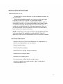
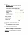
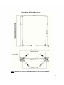
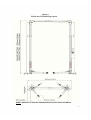
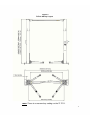
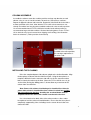
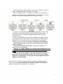
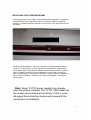
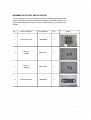
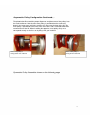
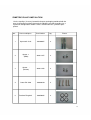
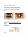
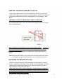
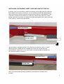
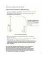
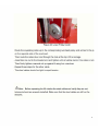
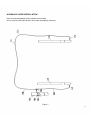
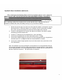
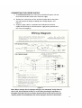
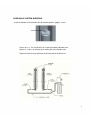
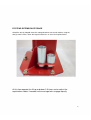
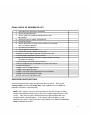
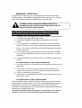
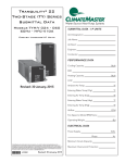
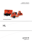
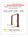
LAUNCH TECH USA INC. LAUNCH LAUNCH Installation, Operation & Maintenance Manual Two Post Surface Mounted Lifts TLT210-A TLT210-AS 10,000 lb. Capacity 10,000 lb. Capacity 2,500 lbs. per Arm 2,500 lbs. per Arm TLT210-XT 10,000 lb. Capacity 2,500 lbs. per Arm TLT211-AS 11,000 lb. Capacity 2,750 lbs. per Arm Model TLT210-AS pictured IMPORTANT: 1820 S Milliken Ave. READ THIS MANUAL COMPLETELY BEFORE INSTALLING OR OPERATING YOUR LIFT Ontario, California 91761 Telephone: 562 463-1580 www.launchtechequipment.com Fax: 562 463-1590 OWNER / EMPLOYER OBLIGATIONS 1. The Owner/Employer shall ensure that lift operators are qualified and that they are trained in the safe use and operation of the lift using the manufacturer's operating instructions; ALI/SM 93-1, ALI Lifting it Right safety manual; ALI/ST-90 ALI Safety Tips card; ANSI/ALI ALOIM-2008, American National Standard for Automotive Lifts - Safety Requirements for Operation, Inspection and Maintenance; ALI/WL Series, ALI Uniform Warning Label Decals/Placards; and in the case of frame engaging lifts, ALI/LP-GUIDE, Vehicle Lifting Points/Quick Reference Guide for Frame Engaging Lifts. 2. The Owner/Employer shall establish procedures to periodically inspect the lift in accordance with the lift manufacturer's instructions or ANSI/ALI ALOIM-2008, American National Standard for Automotive Lifts Safety Requirements for Operation, Inspection and Maintenance; and the Employer shall ensure that the lift inspectors are qualified and that they are adequately trained in the inspection of the lift. 3. The Owner/Employer shall establish procedures to periodically maintain the lift in accordance with the lift manufacturer's instructions or ANSI/ALI ALOIM-2008, American National Standard for Automotive Lifts Safety Requirements for Operation, Inspection and Maintenance; and the Employer shall ensure that the lift maintenance personnel are qualified and that they are adequately trained in the maintenance of the lift. 4. The Owner/Employer shall maintain the periodic inspection and maintenance records recommended by the lift manufacturer's instructions or ANSI/ALI ALOIM-2008, American National Standard for Automotive Lifts - Safety Requirements for Operation, Inspection and Maintenance. 5. The Owner/Employer shall display the lift manufacturer's operating instructions; ALI/SM 93-1, ALI Lifting it Right safety manual; ALI/ST-90 ALI Safety Tips card; ANSI/ALI ALOIM-2008, American National Standard for Automotive Lifts - Safety Requirements for Operation, Inspection and Maintenance; ALI/WL Series, ALI Uniform Warning Label Decals/Placards; and in the case of frame engaging lifts, ALI/LPGUIDE, Vehicle Lifting Points/Quick Reference Guide for Frame Engaging Lifts in a conspicuous location in the lift area convenient to the operator. 6. The Owner/Operator shall provide necessary lockout/tagout means for energy sources per ANSI Z244.1-1982 (R1993), Safety Requirements for the Lockout/Tagout of Energy Sources, before beginning any lift repairs and maintenance. 2 7. The Owner/Employer shall not modify the lift in any manner without the prior written consent of the manufacturer. IMPORTANT SAFETY INSTRUCTIONS 1. When using this lift, basic safety precautions should always be followed, including the following: 2. Read all instructions in this manual and on the lift thoroughly before installing, operating, servicing or maintaining the lift. 3. Care must be taken as burns can occur from touching hot parts. 4. Do not operate equipment with a damaged cord or if the equipment has been dropped or damaged - until it has been examined by a qualified service person. 5. Do not let a cord hang over the edge of the table, bench, or counter or come in contact with hot manifolds or moving fan blades. 6. If an extension cord is necessary, a cord with a current rating equal to or more than that of the equipment should be used. Cords rated for less current than the equipment may overheat. Care should be taken to arrange the cord so that it will not be tripped over or pulled. 7. Always unplug equipment from electrical outlet when not in use. Never use the cord to pull the plug from the outlet. Grasp plug and pull to disconnect. 8. Let equipment cool completely before putting away. Loop cord loosely around equipment when storing. 9. To reduce the risk of fire, do not operate equipment in the vicinity of open containers of flammable liquids (gasoline). 10.Adequate ventilation should be provided when working on operating internal combustion engines. 11.Keep hair, loose clothing, fingers, and all parts of body away from moving parts. 12.To reduce the risk of electric shock, do not use on wet surfaces or expose to rain. 3 13.Use only as described in this manual. Use only manufacturer's recommended attachments. 14.ALWAYS WEAR SAFETY GLASSES. Everyday eyeglasses only have impact resistant lenses, they are not safety glasses. 15.Inspect lift daily. Do not operate if it malfunctions or problems have been encountered. 16.Never attempt to overload the lift. The manufacturer's rated capacity is shown on the identification label on the power side column. Do not override the operating controls or the warranty will be void. 17.Before driving vehicle between the towers, position the arms to the drivethrough position to ensure unobstructed clearance. Do not hit or run over arms as this could damage the lift and/or vehicle. 18.Only trained and authorized personnel should operate the lift. Do not allow customers or bystanders to operate the lift or be in the lift area. 19.Position the lift support pads to contact the vehicle manufacturers recommended lifting points. Raise the lift until the pads contact the vehicle. Check pads for secure contact with the vehicle. Check all arm restraints and insure they are properly engaged. Raise the lift to the desired working height. 20.Some pickup trucks may require an optional truck adapter to clear running boards or other accessories. 21.NOTE: Always use all 4 arms to raise and support vehicle. 22.Caution! Never work under the lift unless the mechanical safety locks are engaged. 23.Note that the removal or installation of some vehicle parts may cause a critical load shift in the center of gravity and may cause the vehicle to become unstable. Refer to the vehicle manufacturer's service manual for recommended procedures. 24.Always keep the lift area free of obstruction and debris. Grease and oil spills should always be cleaned up immediately. 25.Never raise vehicle with passengers inside. 26.Before lowering check area for any obstructions. 27.Before removing the vehicle from the lift area, position the arms to the drive-thru position to prevent damage to the lift and /or vehicle. 4 28.Do not remove hydraulic fittings while under pressure. WARNING! Failure by purchaser to provide the recommended mounting surface could result in unsatisfactory lift performance, property damage, or personal injury. LOCATION This lift has been evaluated for indoor use only with an operating ambient temp. range of 5 - 40°C (41104°F) For additional safety instructions regarding lifting, lift types, warning labels, preparing to lift, vehicle spotting, vehicle lifting, maintaining load stability, emergency procedures, vehicle lowering, lift limitations, lift maintenance, good shop practices, installation, operator training and owner/employer responsibilities, please refer to "Lifting It Right" (ALI/SM) and "Safety Tips" (ALI/ST) and vehicle lift points for service garage lifting SAE J2184. For additional instruction on general requirements for lift operation, please refer to "Automotive Lift-Safety Requirements for Operation, Inspection and Maintenance" (ANSI/ALI ALOIM). Installation shall be performed in accordance with ANSO/ALI ALIS, Safety Requirements for Installation and Service of Automotive Lifts. ATTENTION! This lift is intended for indoor installation only. It is prohibited to install this product outdoors. Operating environment temperature range should be 41 - 104 °F (5 - 40 °C). Failure to adhere will result in decertification, loss of warranty, and possible damage to the equipment. 5 SAFETY AWARENESS REFERENCE: AUTOMOTIVE LIFT INSTITUTE (ALI) SAVE THESE INSTRUCTIONS Note: Some images in this manual are generic and may not resemble the lift you have purchased. 6 SPECIFICATIONS LAUNCH TECH USA TLT Series Specifications TLT211-AS 11,000 lb. Capacity A . Maximum Lifting Height B. Minimum Column Height C. Cylinder Full Height D . Total Width TLT210-AS / XT 10,000 lb. Capacity TLT-210-A / XT 75.6" (1920mm) 76.4" (1940mm) 76.4" (1940mm) 143" (3634mm) 143" (3634mm) 143" (3634mm) 145.2" (3688mm) 145.2" (3688mm) 145.2" (3688mm) 137.8" (3500mm) 136.6" (3470mm) 137.9" (3502mm) 10,000 lb. Capacity E. Drive-Thru Clearance 96" (2438mm) 98.4" (2500mm) 92" (2338mm) F. Floor to Overhead Switch 140" (3556mm) 140" (3556mm) 140" (3556mm) 23.6"(600mm) / 39.4" (1000mm) 23.6"(600mm) / 43.5" (1105mm) 23.6" (600mm) / 43.5" (1105mm) G . Front Arm Reach (min / max) H. Rear Arm Reach (min / max) 38.6" (980mm) / 61.8" (1570mm) 38.6" (980mm) / 61.8" (1570mm) 38.6" (980mm) / 61.8" (1570mm) I. Screw Pad Height 4.3" (110mm) to 7.5" (190mm) 4.3" (110mm) to 7.5" (190mm) 4.3" (110mm) to 7.5" (190mm) . Inside Column Width Electric Hydraulic Power Unit Voltage 108" (2742mm) 110.2" (2800mm) 101.9" (2588mm) 2 HP 2 HP 2 HP 208-230Volt/60hz./Single Phase 208-230Volt/60hz./Single Phase 208-230Volt/60hz./Single Phase Rise Speed 54 Seconds 54 Seconds 54 Seconds Max. Load Per Arm 2750 Lbs. (1247 Kilos) 2500 Lbs. (1134 Kilos) 2500 Lbs. (1134 Kilos) Minimum Ceiling Height Required 143.9" (3655mm) 143.5" (3644mm) 143.5" (3644mm) Narrow Bay Setting Non-Adjustable Deduct 5.9" (149mm) Deduct 5.9" (149mm) Maximum Column Height 149" (3784mm) 149" (3784mm) 149" (3784mm) 2700 PSI 2750 PSI J Power Unit Operating Pressure 2750 PSI Figure 1 Rise height measured with footpads in the highest position. Lift capacity rating is based on loads equally distributed on all four arms. Lifting and lowering speeds may vary depending on the weight of the vehicle. 7 PACKING LIST The complete lift is contained in two (2) packages: 1. The main structural components and parts are packed in a steel frame. 2. Power Unit Box including Shutoff Switch and all Documents Main Structural Components and Parts 1pc. - Power side tower and carriage assembly 1pc. - Slave side tower and carriage assembly 1pc. - Overhead Beam 1pc. - Actuator Bar w/ foam 1pc. - Power side column extension 1pc. - Slave side column extension 2pc. - Two front arm assembles (Three piece design) 2pc. - Two rear arm assembles (Two piece design) 2pcs. - Safety Covers w/Decals 1pc. - Hardware Package w/Packing List 1pc. - Actuator Extension 1pc. - Actuator Mounting Bracket 1pc. - Safety Release Cable 2pc. - Hydraulic Hose (Long) 2pc. - Hydraulic hose (Short) 2pcs. - Equalizing Cable w/Hex Nuts 1pc. - ALI manual "Lifting It Right" - Automotive Lift Safety Tips 1pc. - Automotive Lift, Operation, Inspection and Maintenance Manual 1pc. - ALI" Quick Reference Guide 1pc. 1pc. - Owner's manual - Warranty Statement and Warranty Registration Instructions 1pc. 1pc. - Power Unit Box with Microswitch and Document Package 8 INSTALLATION REQUIREMENTS AND TOOLS FOUNDATION IMPORTANT: It is the user's responsibility to provide a satisfactory installation area for the lift. Lifts should only be installed on level concrete floors with a minimum thickness of four inches (4") or 102 mm. Concrete must have a minimum strength of 3500 psi should be aged thirty (30) days prior to installation. Please consult the architect, contractor or engineer if doubt exists as to the strength and feasibility of the floor to enable proper lift installation and operation. A qualified person should be consulted to address seismic loads and other local or state requirements. It is the user's responsibility to provide all wiring for electrical hook-up prior to installation and to insure that the electrical installation conforms to local building codes. Where required, it is the user's responsibility to provide an electrical isolation switch located in close proximity to the lift that will enable emergency stop capability and isolate electrical power from the lift for any servicing requirements. TOOLS a. 16ft. Measuring Tape b. Chalk Line c. Rotary Hammer Drill d. 3/4" diameter or 19mm diameter Masonry Drill Bit e. Hammer f. SAE Wrenches and Ratchet Set g. Metric Wrenches and Ratchet Set h. 2ft. Level i. 4ft. Level j. Pry Bar k.12ft. Step Ladder l. Side Cutters m. Screwdrivers n. 4" x 4" Wooden Blocks (for unpacking) o. 4 gal. ISO 32 Hydraulic Fluid p. Torque Wrench q. Hydraulic Fitting Sealant Compound ( DO NOT USE TEFLON TAPE) Launch *Tech USA recommends Permatex brand part number 54540 OR Loctite brand 545 thread sealant 9 INSTALLATION INSTRUCTIONS When the lift arrives on site: Read the owner's manual and make sure the installation instructions are fully understood. Check for any freight damages. The shipment should be thoroughly inspected as soon as it is received. The signed bill of lading is acknowledgement by the carrier of receipt in good condition of shipment covered by our invoice .If any of the goods called for on your bill of lading are shorted or damaged, do not accept them until the carrier makes a notation on the freight bill of the missing or damaged goods. Do this for your own protection. Check the contents of the accessory and hardware boxes to make sure no parts are missing. NOTE: IT IS DIFFICULT TO COLLECT FOR LOSS OR DAMAGE AFTER YOU HAVE GIVEN THE CARRIER A CLEAR RECEIPT. THE LIFT MANUFACTURER IS NOT RESPONSIBLE FOR ANY FREIGHT DAMAGE. UNPACKING PROCEDURE Important! Place the main structural components on wooden blocks so that the steel shipping frames can be removed. Remove Power Unit Box. Remove the plastic wrapping. Remove the cross member, and the actuator bar. Remove the arms and parts boxes Unbolt the steel shipping frames. Lay each tower on the floor with the carriage side up. Check the installation area for obstructions. (Lights, Heating Ducts, Ceiling, Floor Drains, etc.) 10 BAY LAYOUT IMPORTANT: Always wear PPE (Personal Protection Equipment) when installing or servicing a vehicle lift. Prepare the bay by selecting the location of the lift relative to the walls. Clear the installation area of all packaging materials to avoid trip hazards. Measure midpoint of door. Using measuring tape, scribe two arcs, equal distance from the midpoint. The centerline of the lift occurs between the intersection of the arcs and the midpoint of the door. Note: Leave any additional room for any desired aisle or work area. Recommended minimum clearance around lift is three feet (3 ft.) and above lift is four inches (4"). Ensure clearance conforms to local building and fire codes. Figure 2 Measure the specified distance to draw a second chalk line at 90° for locating the lift towers. Refer to Figure 3 and Figure 4 and Figure 5 below for correct measurements. The lift is centered between the door and the walls of the area. Mark chalk lines at the exact position of each baseplate to show that when installing the columns each baseplate will be position properly. All the dimensions are based on the external border of the base plate. The lift layout is very important. If not done properly, problems may occur during the final assembly and operation Important Notice: For narrow bay installation, deduct 5.9" (150 mm) from the width layouts. 11 Figure 3 TLT210-AS or TLT210-XT Bay Layout Deduct 150mm/5.9 in. from the width dimensions for the narrow installation 12 Figure 4 TLT210-A or TLT210-XT Bay Layout Deduct 150mm/5.9 in. from the width dimensions for the narrow installation 13 Figure 5 TLT211-AS Bay Layout Note: There is no narrow bay setting on the TLT21114 COLUMN ASSEMBLE Assemble the column extensions and the positive carriage stop brackets to each column using 12 sets of 12x35 hex bolts, flat washers, lock washers and nuts. Repeat for opposite column and extension. Determine if the lift will be in the tallest or lowest position at this time. Note that the TLT211-AS column extensions are already assembled and may be preassembled at either the short or tallest position. It is recommended that the TLT211-AS lift be installed at the tallest position to accommodate large and taller vehicles. Recheck the bolt tightness on the TLT211AS as the bolts may have loosened from shipping and handling. See illustration below for reference. (Tallest position shown below) Note: If theTLT-211AS lift is installed at the tallest position, this carriage stop bracket is not to be used. INSTALLING THE COLUMNS Raise the completed power side column upright to the chalked location. Align the baseplate of column with the chalk line layout. Using the baseplate as a template, drill holes into the concrete slab and use the five concrete anchor bolts to attach the column to the floor. (Note: the TLT211-AS lift uses six (6) anchor bolts) During the drilling process, do not allow any movement of the column from the chalk line. Note: Power side column should always be installed first. After the power side column is installed the slave column is raised into position but not anchored to the floor. Installing the overhead beam must be completed before the slave side column is anchored to the floor. Use a four foot level on both sides of the column and use shims under baseplate to level the column in both directions. Ensure that the base plate is completely supported by shims including near the center where it does not contact the floor. 15 Refer to Bay Layout Figures about to ensure that the column is still in the proper position before the anchor bolts are installed Prior to installing anchors, assemble the nut and washer onto anchors. A minimum of six threads must be visible below the surface of the nut. Refer to the figure below while reading through the following instructions. Using a ¾" concrete drill bit and rotary hammer drill, drill ¾" holes for the anchor bolts on the power side column. Drill through the concrete floor. (In case longer anchors are required, supplied anchors can be hammered through concrete). Clean out the drilling dust from the holes and place anchor bolts into the hole. Add the washers and nut to the so that the top of the anchor bolt and top of the nut are flush with each other then hammer in the anchor bolts until they make contact with the baseplate. Hand tighten all anchor bolts. Check that the column is level front to rear and side to side. Adjust shims as required. Torque all anchor bolts to 125 ft.-lbs. continually checking that the column is level as you proceed. USE ONLY A TORQUE WRENCH TO TIGHTEN THE ANCHOR BOLTS DO NOT USE AN IMPACT GUN TO INSTALL OR TIGHTEN THE ANCHOR BOLTS. If anchor bolts do not tighten to 125 ft.-lbs. OR project more than 2 ¼" above the concrete surface due to floor slope, the concrete should be replaced by an appropriate concrete pad. (Consult Product Manufacturer Supplier for further details). At this time the slave column should be raised into position and aligned with chalk marks on the floor. DO NOT ANCHOR THE SLAVE COLUMN AT THIS TIME. Use caution to not move the slave column as is may tip over. 16 INSTALLING THE OVERHEAD BEAM After positioning the slave column at the designated chalk location; assemble the overhead beam on the shop floor to either the narrow or widest lift width hole positions as determined by the chalk line measurements. See the photo below for illustration. Photo below shows the overhead beam assembled at the widest (most common) position. While the overhead beam is still on the shop floor install the provided 4 pulleys (sheaves). Two (2) pulleys on each side of the overhead beam using the parts shown below. Note: Asymmetric installation (rotated column position as shown in figure 5) requires the pulleys to be installed offset to each other using two (2) axles and related parts. Symmetric installation (as shown in figure 4) requires the pulleys to be installed on a common axle using the related parts. See related photos below. Note: Some TLT210 series models may already have the pulleys installed. The TLT211-AS model has the pulleys pre-installed at the factory. If this is case, disregard the instructions below and proceed to the next phase of installation. 17 ASYMMETRIC PULLEY INSTALLATION Use the 4 pulleys (sheaves) located in the parts packaging combined with the parts in the packet marked "Asymmetric Installation" to install the pulleys for an Asymmetric configuration. Below is what is contained in the asymmetric parts packet. No. Name and Specs Part Number Qty. 1 Asymmetric shaft 103200966 4 2 Spacer (Wide) Ⅱ 201011257 2 3 Spacer (Narrow) Ⅰ 201011258 2 4 Retainer Ring 25 103050035 8 Picture 18 Asymmetric Pulley Configuration Continued… …. The photo below illustrated the proper alignment and placement of the pulleys into the overhead beam. Note that the outer pulley is positioned on the overhead beam in the outer most axle holes and that it is closest to the front of the lift. The inner pulley is positioned in the inner most axles holes and is mounted toward the rearward area of the lift. When installing the opposite set of pulleys they must correspond exactly as the first set of pulleys that you installed. Note: Inner pulley is facing to the rear of the lift Note: Outer pulley is facing to front of the lift Symmetric Pulley Assemble shown on the following page 19 SYMETRIC PULLEY INSTALLTION Use the 4 pulleys (sheaves) located in the parts packaging combined with the parts in the packet marked "Symmetric Installation" to install the pulleys for a Symmetric configuration. Below is what is contained in the symmetric parts packet. No. Name and Specs Part Number Qty. 1 Symmetric shaft 103200967 2 2 Spacer (Wide) Ⅱ 201011257 2 3 Spacer (Narrow) Ⅰ 201011258 2 4 Cotter Pin 5x40 103060349 4 5 Retainer Ring #25 103050035 4 Picture 20 Symmetric Pulley Installation Continued… … The photos below illustrate the proper alignment and placement of the pulleys (sheaves) into the overhead beam. Note that both pulleys are positioned on the overhead beam sharing a common axle and the axle is positioned in the outer most axle holes and that is closest to outer most area of the overhead beam. Install both sets of pulleys on each end of the over beam to exactly match each other. ASYMETRIC OVERHEAD BEAM INSTALLATION Lift the overhead beam to the level of the column tops and use the provided fasteners to attach it to the upper columns and the transitional brackets. If you are installing for an Asymmetric configuration the column mounting bolts must be aligned as show below. IMPORTANT: HAND TIGHTEN THE BOLTS ONLY AT THIS TIME The drawing below outlines where the overhead beam bolt positions are used on the transitional brackets Figure 21 SYMETRIC OVERHEAD BEAM INSTALLATION Lift the overhead beam to the level of the column tops and use the fasteners to attach it to the upper columns and the transitional brackets. If you are installing for a Symmetric configuration the column mounting bolts must be aligned as show below. IMPORTANT: HAND TIGHTEN THE BOLTS ONLY AT THIS TIME The drawing below outlines where the overhead beam bolt positions are used on the transitional brackets Figure 6 When installing the overhead beam, ensure the microswitch support (It is the Ushaped bracket welded to the bottom of the overhead beam) is adjacent to the power side column location. This will allow you to route the microswitch cord through the end of the overhead beam and down the outside of the power unit column. . Note: Since the idler column is not secured to the floor by the bolts at this stage, be careful to not move the idle column as it is not anchored to the floor. SLAVE SIDE COLUMN INSTALLATON Measure the distance between the top and bottom of each column to insure the columns are parallel to each other. Finish leveling, anchor bolt drilling, shimming if needed and the anchor bolt installation of the slave side column at this time as instructed above for the power unit column.. After the slave side column has been installed proceed back to the overhead beam section and tighten all connection bolts and nuts of the overhead beam and the transitional brackets before proceeding to the next section. 22 INSTALLING THE PADDED SAFETY BAR AND SHUTOFF SWITCH Install the safety shut-off electrical switch to the bracket on the underside of the overhead beam adjacent to the power unit column. Use the provided shoulder bolt and cotter pin to attach to the bracket and then route the electrical cord up into the overhead beam via the small hole next to the bracket. When this is done the shut-off switch will be in a vertical position. When the shut-off bar is installed shut off bar will protrude into the open end of the safety switch as shown in the photo below. Power Unit Column Electrical Safety Shut-Off Switch Padded Shut-Off Bar After inserting the rounded end of the shut off bar into the electrical switch (as shown above) connect the flatted end of the padded shut off bar to the underside of the overhead beam adjacent to the slave side column using the provided should bolt and nut. See photo below for reference. Slave Side Column Shoulder Bolt Note: The Electrical Shutoff Switch cord will be connected when the power unit is installed. 23 INSTALLING THE EQUALIZATION CABLES Note: For the widest and tallest configuration the cables must be connected to the lowest innermost hole inside the carriage. For either the narrow or shortest configuration the cables must be connected to the middle hole inside the carriage. For both the narrow and shortest configuration the cables must be connected to the top hole inside the carriage and you must use the cable tube extensions (They look like a 1"x6" diameter pipe) so the cable bolts can be tightened. 24 25 HYDRAULIC HOSE INSTALLATION Refer to the drawing below for the hydraulic hose location. Please reference the hydraulic hose instructions preceding the drawing. Figure 7 26 Hydraulic Hose Installation continued… … After referring to the drawing above install the hydraulic hoses in this sequence. Notice: DO NOT USE TYFLON TAPE ON ANY HIGH PRESSURE FITTTINGS. THIS ABOVE GROUND TWO POST LIFT UTILIZATES ONLY HIGH PRESSURE HYDRAULIC OIL FITTINGS. TYFLON TAPE IS ONLY DESIGNED FOR LOW PRESSURE WATER PIPE. Use only high pressure oil sealant compound to the male and female threads. Failure to properly seal the hydraulic lines and fittings could result in hydraulic leaks and or hydraulic failure. Hydraulic leaks due to improper installation will not be covered by warranty or any manufacturer liability. 1. Remove the plastic pugs from the base of the hydraulic cylinders and attach the two (2) flow control valves. (Item #107 above) Use a high pressure oil sealant when installing these valves to prevent leakage. Be careful to not over tighten these threads. 2. Install the short hydraulic hose (Item # 106 above) to the power side column cylinder connecting at the flow control valve. 3. Install the "T" fitting to the short hydraulic hose. (Item 105 above) 4. Connect the long hydraulic hose (Item #104 above) to the "T" fitting. 5. Connect the medium length hose (Item #112) to the long hydraulic hose using the hose connector (Item # 111) midpoint inside of the overhead beam assemble. 6. Connect the medium length hydraulic hose to the flow control valve (Item #107) on the slave side column. Note: The hydraulic hose that go through the overhead beam must be positioned inside the hose brackets mounted in the base of the overhead beam to protect the hoses from rubbing on the equalizing cables. Use the provided plastic zip ties to attach the hose to the three (3) brackets to prevent movement. See photo below for reference. 27 SAFETY SHUTOFF SWITCH It is very important to keep proper clearance between shutoff switch electrical cord and the steel cable. Use the provided plastic ties to connect the electrical cord and hose together to avoid any possible damage caused by interference between the electrical cord and the steel cable. Shutoff Switch Electrical Cord Plastic Tie Steel Cable Hydraulic Hose Single Point Lock Release Cable The electrical cord will route over the outer edge of the overhead beam as shown above and downward to the power unit junction box. 28 POWER UNIT INSTALLATION 1) 2) 3) 4) 5) 6) Remove the power unit from the shipping box. Remove the red plastic plug on the oil tank. Remove the black breather cap on the lower section of the oil tank. Install the black breather cap into the fill hole at the top of the tank. Install the red plastic plug into the hole at the bottom of the tank. After removing the plastic plug on the side of the power unit valve body install the 90 degree hydraulic fitting using high pressure sealant compound. DO NOT USE TEFLON TAPE. 7) Use the provided bolts and washers to secure the power unit to the power unit mounting bracket. 8) Use 5/16x18 bolts and washers (see fig. 8) to secure the power unit. Push Start Button Lowering Lever Figure 8 After the securing the power unit to the column, remove the black breather cap and fill the reservoir with approx. 4.5 gallons (18 liters) of ISO-32 hydraulic oil (10 weight hydraulic oil) DO NOT USE TRANSMISSION FLUID or reclaimed hydraulic oil. Use of transmission fluid or reclaimed hydraulic oil will void the manufacturer's warranty. Note: Use caution to avoid dust and other pollutants mixing with the hydraulic oil while filling the power unit by using a clean funnel and clean paper strainer. After the power unit has been mounted, install and connect the one remaining short hydraulic hose to the 90 degree elbow and connect to the "T" fitting. For lifts that have an SPX brand power unit, review the wiring diagram that is attached to the inside cover of the push button junction box. 29 CONNECTING THE POWER SUPPLY 1) A certified electrician must connect the 230Volt/1Ph power unit and the overhead Shutoff Switch to the electrical supply. 2) Remove the sealed cover on the electrical junction box on the power unit and connect the wiring according to the wiring diagram. See Figure 9 3) A power supply switch is required to be installed near the lift for rapidly disconnecting the electrical power supply during maintenance or in case of emergency. Figure 9 Note: Motor damage due to improper wiring is not warranted. Verify if the oil tank is full; do not operate if there is no oil. After pressing the up button, if the power unit does not run or makes unusual noises or has excessive heat stop the power unit immediately and check of proper electrical connections. 30 HYDRAULIC SYSTEM BLEEDING Crack the bleeder valve located at the top of both cylinders (approx. ¼ turn) Power up 2"-3". You should hear air escaping around the bleeder valve. Repeat 3 - 4 times or until only oil is coming out of the bleeder valve. Tighten the bleed screw and lower the lift and recheck oil tank level. 31 After bleeding the hydraulic system and checking for leaks, install all of the metal hose covers. In the parts box you will find small threaded bolts with the top of the bolt drilled and taped. Install these bolts into the predrill holes on the side of each column. On the power unit side at the hydraulic "T" fitting a special hose cover with a cutout to allow for the "T" connectors shall be used. Cover each section of the hose and then use the marching bolts to attach the hose covers to the special predrilled bolts. Reference the photo below that shows the "T" fitting and hose covers. Hose cover studs and screws Hose from the Power Unit shown Hose cover cutout 32 SAFETY RELEASE CABLE ROUTING AND ADJUSTMENT The mechanical safety automatically engages. To release the mechanical safety, you must first raise the lift approximately 2", and then pull the safety release lever down. This disengages the power side safety locks and activates the safety cable to release the slave side safety lock. Included in the parts packaging you will find the extra-long steel single point lock release cable, cable clamps and four (4) metal cable guides and two (2) white nylon cable guides with two (2) small retaining rings. Using the provided bolts attach one metal cable guide to the inner edge at the top of each column. Attach another metal cable guide to the outer inside edge of the overhead beam. See the photo below for reference. Single Point Lock Release Cable Guides mounted to the column and to the overhead beam. Mount as shown to both columns. For the TLT211-AS model a cable guide is not used on the overhead beam. 33 Attach the two (2) provided white nylon cable guides using the retaining rings onto the horizontal metal post just above the carriage locking mechanism on the slave side column. Inspect the metal post for any paint overspray and clean with sandpaper if necessary. Use a small amount of general purpose grease on the metal post prior to installing these cable guides. Attach the steel cable to the large metal post on the slave side column side using the provided cable clamps. See the photo below for reference. Slave Side Column Next route the steel cable under the nylon cable guide as shown above on the inside of the column and up into the bottom hole of the metal cable guide on the mounted on top of the column. Continue to route the cable over the top of the metal roller wheel on the metal cable guide and over the top of the metal cable guide mounted on the overhead beam and exit on the metal cable guide hole as shown in the metal cable guide photo above. Complete the routing of the cable across the overhead beam and down the power unit column repeating the same route used on the slave side column. Route the steel cable through the white nylon cable guide ABOVE the carriage release on the power unit side and then connect the cable as shown below. 34 Power Unit Column Adjust the slack in the single point lock cable at the power unit side so that when the release lever is pulled down both carriage locks will disengage. Tighten the cable clamps and install the carriage lock covers on each side with the four (4) provided screws. (Factory tip: Adjust the cables to release the locks just before the lock release lever has reached maximum travel…this prevents overstretching the cable). At this time install the carriage lock covers and install the release lever on the power unit column. INSTALLING THE LIFT ARM ASSEMBLES All four (4) arms come completely assembled. The long 2-piece arms are mounted to the rear of the lift and the shorter 3-piece arms are mounted to the front of the lift. Insert the arm assembles in the correct gaps in the carriage. Align the holes in the carriage with the holes in the carriage and insert the metal arm pivot pins. Repeat for all arms. When the arms pivot pins have been installed use the provided metal retaining rings and attach them to the grooves in the bottom edge of the arm pivot pins to prevent these pivot pins from moving upward. See photo below for reference. 35 FOOTPAD EXTENSION STORAGE Attach the two (2) footpad extension storage brackets one to each column using the two (2) metal screws. Store the footpad extensions as show in the photo below. At this time operate the lift up and down 2-3 times and re-adjust the equalization cables if needed so the carriage locks engage equally. 36 FINAL CHECK OF ASSEMBLED LIFT 1. Final dimension check after anchoring 2. Check for hydraulic leaks. 3. Ensure cables are properly routed and free from obstructions. 4. Check jam nuts on cables are tightened. 5. Check for oil leaks. 6. Check adjustment of safety release cable to ensure both sides are working properly. 7. Re-check level of towers. 8. Check torque of anchor bolts. 9. Check all fasteners, tighten if necessary. 10.Check shut off at top of stroke to ensure lift shuts off. 11.Check proper operation of arm restraints. 12.Operate lift to full stroke then lower to ground while checking for proper functionality. 13.Check proper operation of arm restraints. 14.Ensure all documents listed below are given to the owner. 15.Operation Manual 16.ANSI / ALI Lift It Right Manual 17.ANSI / ALI Safety Tip Card 18.ANSI / ALI ALIS Safety Requirements for Installation 19.ANSI / ALI Quick Reference Guide 20.Train end user on operation of lift. OPERATING INSTRUCTIONS Read and understand all safety and operation labels on the lift. Refer to the "Lifting it Right" manual and "Safety Tips" card supplied to you for additional important instructions and information. NOTE: Some vehicles may have the manufacturer's Service Garage Lift Point locations identified by triangle shape marks on its undercarriage (reference SAE J2184). Also, there may be a label located on the right front door lock face showing specific vehicle lift points. If the specific vehicle lift points are not identified, refer to the "Typical Lift Points" figure below or the ANSI/ALI Lift Point Guide included with your lift. 37 1. Position arms to drive-thru position. 2. Refer to supplied literature prior to loading vehicle. Center the vehicle between the lift posts. 3. Only lift the vehicle on the manufacturers recommended lift points. Refer to supplied lift points guide (reference ANSI/SAE J2184-1992). 4. Locate lift pads on auto manufacturer's recommended lift points. Once you have correctly positioned the lift arms, ensure that all arm restraints are properly engaged. 5. Raise the vehicle by pushing the "UP" button on the power pack until the vehicle's suspension has left the ground. 6. Inspect to make sure there is no interference with any objects and for proper engagement of the lifting pads. 7. Shake vehicle moderately by pushing on either the front or rear bumper. Visually inspect the lifting pads again. If the vehicle starts slipping on the lifting pads, or otherwise appears unstable on the lift, you have positioned the swing arms and adapters incorrectly. Carefully lower the lift and start over. 8. When satisfied, continue lift the vehicle to the desired working height, lower onto the mechanical safety using the lowering lever. 9. Once vehicle is ready to be removed, raise lift so that the mechanical safety can be released. Pull down and hold the mechanical safety release lever, then press the hydraulic lowering lever until the lift has fully collapsed to the grounds and the arm restraints are disengaged. 10.Swing the lift arms to the drive-thru position prior to moving the vehicle. 38 OPERATION TEST WITH VEHICLE Prior to starting this section, please refer to Section 2 of this manual for important safety instructions. 1. Lower lift to ground. 2. Drive vehicle on to lift and locate the arms as per the "Lift it Right" manual. 3. Raise lift to and lower onto 3-4 lock positions during full rise to ensure all locks are working correctly. 4. Re-adjust cables if necessary while vehicle is on. 5. Check lowering speed and smooth decent rate. 6. Lower lift to ground and drive vehicle off lift. If any problems occur during the final checkout or operation of the lift please contact your lift distributor, sales representative or the manufacturer. 39 MAINTENANCE GUIDELINES SAFETY INSTRUCTIONS Refer to Section 2 for more Safety Instructions. Read operating and safety manuals before using any lift. Do not operate a lift that has been damaged or is in disrepair. Proper inspection and maintenance is necessary for safe operation. PERIODIC MAINTENANCE DAILY: 1. 2. 3. 4. 5. 6. Check all hydraulic lines and fittings for pinch points , damage , cracks or leaks Check all electrical wiring for pinch points , cracks or damage Check all moving parts for uneven or excessive wear Repair or replace all damaged, defective, worn or broken components immediately. Check the telescopic arms for movement. Clean any grease or oil from the lifting adapters. Raise and lower the lift at the beginning of each shift, without a vehicle on, to verify the lift is leveled and operating properly. EVERY TWO MONTHS: 1. Clean and re-grease slide block channels inside of both columns 2. Grease arm pins 3. Lubricate safety dogs and check safety release cable adjustment 4. Check arm restraints and lubricate 5. Check anchor bolts and re-torque if required EVERY FOUR MONTHS: 1. Dismantle and clean inner arms 2. Lubricate cable pulleys 3. Check equalizing cable adjustment EVERY YEAR: 1. Inspect lift as per Automotive Lift Operation, Inspection and Maintenance (ALOIM) EVERY TWO YEARS: 1. Change hydraulic fluid LUBRICATION: Where grease is required > multi-purpose lithium grease Where lubricating oil is required > multi-purpose SAE 30 lubricating oil Where hydraulic oil is required > ISO 32 10W - non detergent hydraulic oil NOTE: If the lift locks, while in the fully raised position this will indicate that the hydraulic system has not been inspected or maintained as recommended. This is a safety back-up system. If you are unclear call your local representative immediately. 40 WIRE ROPES Wire ropes are critical to safe and reliable performance of your lift. Cables are expendable items and should be replaced as a set. WIRE ROPE CONDITION GUIDE Typical good cable Cable with necking Broken wires Excessive wear of wires Rust on sheave stack and ropes Corrugated sheave groove (Pictures above are of a 4-Post Lift, conditions still apply to 2-Post Lifts) 41 WIRE ROPE REPLACEMENT CRITERIA: If any cable is found to be in need of replacement, the entire cable set, pulleys and safety rollers must be replaced immediately. See cable conditions guide. In the following table, "lay" means the distance measured along a line parallel to the axis of the rope in which the strand makes one complete turn about the axis of the rope, or the wires make a complete turn about the axis of the strand. The wire rope must be removed from service if one or more of the following criteria are met: 1. More than six randomly distributed broken wires in one rope lay or 6 d length. 2. More than three broken wires in one strand in one rope lay or 6 d length. 3. Three or more broken wires at rope terminations. 4. One outer wire broken at the point of contact with the core of the rope which has worked its way out of the rope structure and protrudes or loops out from the rope structure 5. Heavy rusting, corrosion, or pitting. A light surface corrosion on outer wires is normal. 6. Wear or scraping of one-third of the original diameter of outside individual wires 7. Excessive stretch. It is normal for new cable to require adjustment during "break-in", after which small periodic adjustments may be required. However, if a cable that has been in service for 6 months should suddenly require frequent adjustments has used all the cable adjustment available, all cables must be replaced immediately. 8. Deformed strands, kinking, crushing, bird-caging, or any other damage or distortion of wire rope structure 9. Variations in diameter (necking) or any change from normal appearance 10.Reductions from nominal diameter of more than 1/32" (for cables or 3/8" to 1/2" dia. inclusive) WIRE ROPE INSPECTION 11. Inspect End wire attachments rope cables cracked, for wear deformed or damage. or worn Wipe cables with a rag to detect hard to see small broken or frayed cable strands. See chapter 9.2, Fig.75 and ANSI/ALI ALOIM standard. 42 WIRE ROPE LUBRICATION Lubricate wire ropes with lift in both lowered and raised position, by spraying them with wire rope lubricant (i.e. 2001 MONOLEC®) and wiping the cable down. WIRE ROPE ADJUSTMENT Adjust cables if lifting is uneven or lift is not level (See chapter 7.15.3). Never make adjustments with weight on lift. If running out of adjustment threads, cables need to be replaced. Do not add washers or other spacers to re-use previously used adjustment threads. Wire rope tension adjustment should be performed when installing the lift and every three months. 43 MAINTENANCE SCHEDULE Maintenance and Training Performed Date By Notes 44 TROUBLESHOOTING GUIDE PROBLEM Power Unit (Motor) not running. REASON Bad Fuse or Circuit breaker. SOLUTION Replace bad fuse or reset circuit breaker. Incorrect voltage to motor. Provide proper voltage to motor. Improper wiring. Have certified electrician check wiring. Power Unit up switch not functioning. Replace Power Unit up switch. Overhead Microswitch not functioning. Replace overhead Microswitch. Power Unit motor burned out. Replace motor. Low oil level. Fill reservoir with proper hydraulic oil. Lowering valve remains open. Repair or replace oil valve. Pump sucking air. Tighten all fittings and suction lines. Lift goes up slowly or oil coming out from filler cap. Air in hydraulic fluid lines Bleed hydraulic lines (Call installer). Lift doesn't come down. Dirt in directional valve Call installer to clean valve. (Do not attempt to open hydraulic lines unless vehicle is secure) Safety Locks do not engage. Safety lock jammed. Safety Lock does not disengage. Safety lock is being limited Oil or replace pin to free Safety Lock. Check or replace spring. Check for any obstructions. Lift goes up unlevel. Equalizing cables are loose. Adjust equalizing cables to correct tension. Floor unlevel. Shim lift to make towers level. (Do not exceed ½" of shimming). Low oil level. Fill reservoir to correct level with proper hydraulic oil. Air in hydraulic fluid lines/cylinder. Bleed hydraulic lines. (Call installer). Holes are too large. Relocate lift using proper size drill bit. Incorrect concrete floor specification (Thickness and holding strength). Break existing floor and pour new pad for lift. Lift out of plumb. Plumb columns. Unlevel floor. Replace floor of shim columns. Worn arm or carriage holes. Replace parts. Worn carriage slide blocks. Replace side blocks. Bent arm (Overloaded). Replace arm. Also check damage to carriage. Power Unit (Motor) runs but lift does not go up. Lift goes up with chatter or does not fully rise. Anchor bolts do not stay tight. Noticeable Deflection of Arm or arm dragging on floor. 45 LOCK OUT AND TAG OUT INSTRUCTIONS IMPORTANT: This machine does not have integral devices that will isolate the electrical, pneumatic, stored and hydraulic energy source. Appropriate isolation or blocking devices must be used that have the provisions to be switched in the off position and locked in that position. ALL MAINTANANCE AND SERVICE MUST BE PERFORMED BY A QUALIFIED PERSON. ALL MAINTANANCE AND SERVICE MUST BE PERFORMED WITH THE LIFT UNLOADED. IT IS THE SHOP OWNERS RESPONSIBILITY TO ENSURE ENERGY ISOLATING DEVICES ARE: Accessible Conveniently located to facilitate the application of lockout devices during service and maintenance Located outside any hazardous area. At a convenient manipulating height (i.e. not overhead, on ladders or under machinery) Adequately labeled or marked. Identification shall include machine ID, energy type and magnitude. Capable of being locked or otherwise secured in an effective isolating position. Effective hazardous energy control procedures will protect employees during machine and equipment servicing and maintenance where the unexpected energization, start up or release of stored energy could occur and cause injury, as well as while working on or near exposed de-energized electrical conductors and parts of electrical equipment. Hazards being guard against include being caught in, being crushed by, being struck by, being thrown from, or contacting live electrical circuits/parts. In preparation for lockout, an initial survey must be made to locate and identify all energy isolating devices to be certain which switch, valve, or other energy isolating devices apply to the machine / equipment to be locked out. More than one energy source (electrical, hydraulic, pneumatic, or others) may be involved. SHUT DOWN PROCEDURE Notify all affected employees that a lockout or tagout system is going to be utilized and the reason for. The authorized employee shall know the type 46 and magnitude of energy that the lift utilizes and shall understand the associated hazards. ELECTRICAL: Located at the user control panel, press the "E-STOP" button to disconnect the raise and lower functions. ELECTRICAL ENERGY IS STILL PRESENT AT THE LIFTS ELECTRICAL PANEL WHEN THE EMERGENCY STOP BUTTON IS PRESSED. ELECTRICAL ENERGY MUST BE TURNED OFF AND ISOLATED AT THE DISCONNECT PANEL PRIOR TO PERFORMING SERVICE OR MAINTANANCE ON THE LIFT. ISOLATION AND VERIFICAITON PROCEDURES: Table 1: ISOLATION AND VERIFICATION PROCEDURES: LOCKOUT LOCATION ENERGY TYPE AND SOURCE STORED ENERGY AND HYDRAULIC PRESSURE 3000-5000 PSI (TO BE COMPLETED BY END USER) PROCEDURE FOR LOCING OUT AND OR RELEASING ENERGIES LOWER THE LIFT TO ITS LOWEST REST POSTION. IF THE LIFT MUST BE SERVICED OR MAINTAINED IN THE RAISED POSITION, ENSURE THAT THE LIFT IS PLACED ON THE MECHANICAL LOCKS. FOR SCISSOR LIFTS, ADDITIONAL SUPPORT WITH SUPPLEMENTARY JACK STANDS, BLOCK AT THE SLIDERS AND A COME ALONG SECURED BETWEEN THE SCISSORS. FOR 4-POST LIFTS, ADDITIONAL SUPPORT WITH SUPPLEMENTARY JACK STANDS. VERIFY PROCEDURES VERIFY THAT THE LIFT IS (IF APPLICABLE): CONTACTING THE MECHANICAL LOCKS, RESTING ON THE SUPPLEMENTARY JACK STANDS, BLOCKS ARE SECURLY PLACED COME ALONG IS SECURED BETWEEN THE SCISSORS. 47 AT THE LIFT, PRESS THE EMERGENCY STOP BUTTON COMPLETELY TO DE-ENERGIZE THE CONTROL BUTTONS (IF APPLICABLE). ELECTRICAL 240VOLTS AT THE DISCONNECT PLANEL, PLACE THE DISCONNECT HANDLE IN OFF POSITION. ATTACH A MULTIPLE LOCUOUT DEVICE. LOCK AND TAG. ATEMPT TO RESTART THE SYSTEM, THE SYSTEM MUST NOT START. VISUALLY VERIFY OPEN DISCONNECTS AND LOCKING DEVICE INSTALLED. DANGER: LINE SIDE OF DISCONNECT REMAINS ENERGIZED PNEUMATIC UPTO 160PSI SLOWLY CLOSE LOCKOUT VALVE TO RELEASE AIR PRESSURE GRADUALLY. ATTACH MULTIPLE LOCKOUT DEVICE, LOCK AND TAG. DANGER: LINE SIDE OF DISCONNECT REMAINS PRESSURIZED VERIFY THE VALVE IS CLOSED AND LOCKOUT DEVICE IS PROPERLY ATTACHED. OPERATE THE PNEUMATIC SYSTEM TO ENSURE THE SYSTEM IS DE-ENERGIZED. IT MAY BE NECESSARY TO BLEED THE SYSTEM OF REMAINING COMPRESSED AIR, THIS CAN BE PERFORMED AT THE BASE OF THE WATER SEPARATOR BOWL. RETURNING TO SERVICE: Check the lift and the immediate area around the lift to ensure that nonessential items,, tools and parts are removed and that the lift components are operationally intact. Check the work area to ensure that all employees have been safely positioned or removed from the work area. Notify all employees that the lockout/tagout is going to be removed and the lift is going to restarted. Remove the lockout/tagouts in the reverse order as the installation. Verify the proper operation of the equipment. Notify affected employees that the maintenance/service is completed and the machine is ready for operation. 48 EMERGENCY OPERATION: If the lift becomes inoperative in the raised position, it is best to wait until the electrical power is restored before lowering the vehicle. However, if it's critical to safety that the lift be lowered, the following steps should be taken. WARNING: DO NOT LOOSEN OR REMOVE HYDRAULIC CONNECTIONS OR FITTINGS UNDER PRESSURE. SERIOUS INJURY OR DEATH COULD OCCUR. NOTE: Safely performing this process requires 3 people. All personnel should stay clear of the path of the lift. All tools and other non-secured items should be removed from the surface of the runways. 1) Survey the area surrounding the lift; remove any items and personnel from area before proceeding with this procedure. 2) Perform the appropriate lockout/tag out procedure on the electrical energy. 3) Use a second person standing at a safe distance away from the lift to keep watch on the area, lift, vehicle and other personnel throughout the process. This person should signal the person performing the procedure to stop if necessary. 4) Use a caution tape or similar to barrier the area around the lift to avoid personnel from accidently entering the area while this process is being performed. 5) Do not proceed with this procedure if you are unfamiliar with the lift or its function. IF THE MECHANICAL LOCKS ARE NOT ENGAGED: 1) Pull safety release lever simultaneously pressing the descent lever on the power pack. 2) Keep a close eye on the movement of the lift and the position of the vehicle; release descent lever if any abnormal movement is detected. 3) Continue until the lift is fully lowered. 4) Once power is restored follow the lockout/tag out procedure to return the lift back into service. IF THE MECHANICAL LOCKS ARE ENGAGED: Various methods can be used to raise the lift in order to get sufficient clearance to disengage the mechanical locks. The safest method would employ temporary electrical power to the lift using a portable power generator. Any electrical connections should be done by a licensed electrician; lockout/tag out procedures should also be employed at this time. This process should only be performed by a trained professional. Contact customer service or a local service professional for further assistance. 49 PARTS VIEW AND IDENTIFICATION 26A 3A 1A Part_numbers_with_an_"_"_is_for_the_TLT211-AS Model 50 107A Part_numbers_with_an_"_"_are_for_the_TLT211-AS Model 51 201 201A Parts numbers_with_an_"_"_are_for_the_TLT211-AS model 205 235 206 207 226 204 209 227 208 202 228 223A 223 230 215 231 234 229 217 233 210 216 214 232 224 211 224A 218 212 213 225 225A 221 219 220 219A 222 222A 54 55 No. Part Number Part Number Updated Part Description 201024604 201024604 201024785 Column for TLT210-AS Power Unit Side Column for TLT210-AS Idler 201624622 201024622 Column for TLT211-AS Idler 201624620 201024620 Column for TLT211-AS Power Unit Side 201014670 201014670 Column extension 4 6 7 8 9 10 11 12 13 14 15 201024624 201024608 103010432 103040132 201013268 103020188 201011739 103020164 103040044 103040110 103030129 103040123 201024624 201024608 103010432 103040132 103203019 103020188 201011739 103020164 103040044 103040110 103030129 103040123 Column extension for TLT211- AS Power unit bracket screw M5*12 Flat washer Lateral positioning plate Bolt M5×10 Connection bracket Bolt M12×35 Spring washer Flat washer Nut M12 Flat washer 10 16 103040122 103040122 Spring sealer, GB/T93-1987 11 17 103020207 103020207 Bolt M10×20 18 19 20 21 22 23 24 25 201011740 201011154 103020100 103040134 103040141 103020171 201024606 103020163 201021179 201624629 201020809 201011257 103200699 201013282 103050035 103200966 201011258 103200967 103020126 201011740 201011154 103020100 103040134 103040141 103020171 201024606 103020163 201021179 201024629 201020809 201011257 103200699 103203017 103050035 103200966 201011258 103200967 103020126 Connection bracket Reinforcement plate Bolt M8X25 Flat washer 8 Spring washer, 8 Bolt M6×12 Cable guide block Bolt M6X25 Outer overhead beam bracket Overhead Beam for the TLT211-AS Inner overhead beam bracket Sheave Spacer, Power Side, 8mm Bush, SF-2 2520 Sheave Elastic ring, 25,GB/T894.1- 1987 Asymmetric shaft Spacer I Symmetric shaft Bolt M12*25 1 3 26 27 28 29 30 31 32 33 34 35 Ⅰ Ⅱ 56 36 37 38 39 40 41 42 43 44 45 46 47 48 49 201014671 201014680 104130196 201014671 201014680 104130196 102100206 Shutoff bar Shutoff Bar for the TLT211-AS Sleeve(inner holeФ22),L=1.8M Limit switch TS-10 Limit switchSP-1403-14 201014672 201014673 103030018 103060342 201011477 103260260 103260341 103020117 201014674 201014672 103202751 103030018 103060342 201011477 103260341 103260341 103020117 201025080 Switch bracket Switch shaft Nut M5 Cotter pin 3*26,GB91-87 Shutoff shaft Cable assembly Use this # after August 2013 Anchor bolt M19*140 Column long hood at three-way fitting 201014675 201014676 201014685 201025177 201025081 201025082 103202748 TLT210-AS Idler column bottom hood Column long hood Column short hood Shaft for Hose hood 103 103202113 M-4509-0200 AC-10AH RV21 104120132 104120159 103202113 104 104120134 104120134 Overhead beam hose, L=5370 105 103100294 103100294 Three-way fitting 106 104120133 103100322 104120133 103100322 103100327 103100327 103100323 103100323 Hose, L=930 Flow control fitting assembly Use # this after August 2013 Flow control fitting assembly Flow control fitting for the TLT211-AS 10300328 103100328 103202112 103100295 104120135 103202112 103100295 104120135 104120160 101 102 107 109 111 112 104120132 202 201024611 104990132 TLT211-AS hose Adjustable right angle fitting Use this # after August 2013 Flow control fitting for the TLT211-AS Cylinder Straight fitting Idler column hose L=4250 201024611 TLT211-AS Idler column hose L=4130 TLT211-AS high setting hose,TLT211-AS-50-03A,L=270 Carriage 201021093 TLT211-AS Carriage 104990132 Slide block, strengthen nylon 104120161 201 Bucher Power Unit SPX Power Unit Power unit hose L=880 57 202 204 104990132 104990132 Slide block, strengthen nylon 104990135 104990135 TLT211-AS slide block 104990134 104990134 201011855 201025138 Top board 201025139 TLT211-AS Top board Ⅰ TLT211-AS slide block Ⅱ 205 103010473 103010473 Screw M10x30 206 103040122 103040122 Spring sealer, GB/T93-1987 11 207 103040123 103040123 Ring GB/T95-1985 11 104130191 104130192 TLT series Anti Shock Pad 209 103010539 104130372 103010539 N/A Screw M8×12 210 103202184 103202184 Restraint shaft assembly 211 103060376 103060376 Pin 5*32 212 103060355 103060355 Cotter pin,3.2*30 213 103201914 103201914 Spring 214 103201744 103201744 Small gear block 215 201010982 103202280 Pin shaft 103202778 TLT211-AS Pin shaft 208 216 103010443 103011102 Bolt M10x25 217 103201771 103201771 Big gear block 218 103050030 103050030 Retaining ring 40 219 201021763 201021763 Long female arm 201624631 201024631 Long female arm for TLT211- AS 220 104130186 104130186 Arm rubber pad 221 103010608 103010608 Bolt M6x10 222 201021532 201021532 Long male arm 201024632 201024632 Long male arm for the TLT211- AS 201024616 201024616 Front female arm 201624634 201024634 Front female arm for the TLLT211-AS 201024645 201024645 Front middle arm 201024632 201024635 Front middle arm for the TLT211-AS 201024646 201024646 Front male arm 201024636 201024636 Front male arm for the TLT211-AS 226 104130315 104130315 Rubber pad 227 201021561 201021561 Threaded rod assembly 228 103202107 103202107 Dual-threaded adjustment sleeve 229 103202106 103202106 Support bracket 230 103050091 103050091 Retaining ring,30 223 224 225 58 231 103050090 103050090 Retaining ring,45 232 201014690 103203210 Long extension tube(optional) 201014691 103203209 Short extension tube(optional) 233 201011475 201011475 Positioning plate 234 103010586 103010586 Bolt M8×12-12.9 235 201011741 103203213 Asymmetric adjustable bushing for asymmetric installation 201011742 201011742 Adjustable bushing for narrow style installation 401 104090074 104090074 Lock release mechanism hood 402 201012086 103203057 Lock release plate 403 404 201020584 103201450 103203056 103201450 Cam (Power side) Torsion spring 405 103201451 103201451 Ⅰ Torsion spring Ⅱ 406 103201455 103201455 Lock release plate shaft 407 408 409 412 413 414 415 416 417 418 419 420 421 202010074 103201454 103260186 201011156 104130210 103050021 103060333 103260179 101060019 103201478 103050025 103010393 103040134 103203055 103201454 103260186 103203061 104130210 103050021 103060333 103260179 101060019 103201478 103050025 103010393 103040134 Lock Release roller Lock release latch Latch cover BM10×50 black Adjustment washer I Small rubber pad Retaining ring 9 Pin, 6*40 Cable Clamp 3 Cable,F1.4,L=8901 Cable,φ1.6mm,L=8300mm Cable clamp f2 Retaining ring 20 Screw,M8*12 Washer C,8 422 104090073 104090073 Idler lock release mechanism hood ( ) Revised March 2014 Installation Instructions 59