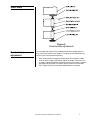
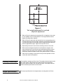
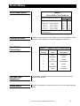
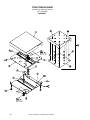
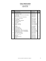
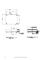
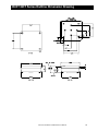
1
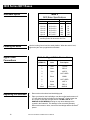
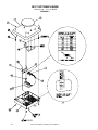
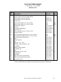
Bench Scale Bases
SELECTEDSCHEMATI
CSANDPARTSLI
STS
Manypar
t
savai
l
abl
eonl
i
ne.Pl
easecal
l
8002252623f
orpr
omptser
vi
ceonot
herpar
t
s.
Installation/Service Manual
2
Bench Scale Bases Installation/Service Manual
Table of Contents
Introduction
..................................................................................... 5
Diamond Base Bench Scales ......................................................... 6
Diamond Base Specs .......................................................... 6
Signal Cable Connections .................................................... 6
Scale Setup .......................................................................... 7
Overload Stop Adjustment ................................................... 7
Cleaning Instructions ........................................................... 8
Torque Specification ............................................................ 8
Drawings and Parts List ................................................ 10-11
Torsion Bases ............................................................................... 13
Torsion Base Specs ........................................................... 13
Leveling the Scale .............................................................. 13
Signal Cable Connections .................................................. 13
Overload Stop Adjustments ............................................... 13
Torque Specs ..................................................................... 13
Drawings and Parts List ................................................ 14-15
3600 Series QDT Bases ............................................................... 16
3600 Base Specs ............................................................... 16
Leveling the Scale .............................................................. 16
Signal Cable Connections .................................................. 16
Replacing the Loadcell ....................................................... 16
Overload Stop Adjustments ............................................... 17
Torque Specs ..................................................................... 17
Drawings and Parts List ................................................ 18-23
3700 Series Bases
3700 Base Specs ............................................................... 25
Leveling the Scale .............................................................. 25
Signal Cable Connections .................................................. 25
Overload Stop Adjustments ............................................... 25
Torque Specs ..................................................................... 25
Assy Drawings/ Parts, Outline Drawings ....................... 26-46
Pages are numbered consecutively beginning with the cover page.
Bench Scale Bases Installation/Service Manual
3
This page left intentionally blank.
4
Bench Scale Bases Installation/Service Manual
Introduction
Weigh-Tronix bench scales are divided into three types:
• Diamond series bench scale analog bases
• Torsion series bench scale analog bases
• 3600 series bench scale Quartzell bases
• 3700 series bench scale analog bases
This manual is divided into major sections dealing with each of these bench
scale base types. There is some information which applies to all of the
bases. This information is given below.
Weigh-Tronix bench scale bases are available in stainless steel for use in
sanitary or hostile environments and in painted carbon steel for use at less
demanding sites. The Weigh-Tronix weight sensor is potted to provide
corrosion resistance and to permit cleaning. A built-in bubble level and
adjustable feet provide convenience in leveling the scale.
Place the scale on a flat, rigid, vibration-free surface. For the diamond series
or torsion series bench scales, lift the scale platform straight up, removing it
from the frame. Figure 1 shows the diamond series scale. Figure 2 shows
the torsion series bench scale. See Figure 3 for the 3600 series and Figure
4 for the 3700 series. Loosen each leveling-foot lock nut, as required. Adjust
the leveling feet until the bubble level shows that the frame is level. All
leveling feet must be in firm contact with the mounting surface. Make sure
that the weight sensor signal cable is routed properly and will not interfere
with platform movement. Tighten each leveling foot lock nut as required.
Bench Scale Bases Installation/Service Manual
5
Diamond Base Bench Scales
Diamond Base Specs
Table 1
Diamond Base Specifications
Platform Dimensions
Capacity
Inches
Centimeters
lb
kg
14 x 14
35.56 x 35.56
30
13.61
18 x 18
45.72 x 45.72
50
22.68
18 x 24
45.72 x 60.96 100/200 50/100
20 x 20
50.80 x 50.80
100
45.35
24 x 24
60.96 x 60.96
200
90.70
Torque spec is 55 ft lbs for the mounting bolts
Weigh Bar
Output (mV/V)
0.6
1.0
1.0
1.0
1.0
Figure 1
Platform Leveling Adjustments
Signal Cable
Connections
Table 2: Signal Cable Connections
Terminal
(NEMA IV)
Wire
Color
Description
Desktop
Connections
1
GRN
+Excitation
B
2
YEL*
+Sense
F
3
WHT
+Output
C
4
WHT/ORN
Shield (Gnd)
G
5
RED
-Output
A
6
BLU*
-Sense
E
7
BLK
-Excitation
D
*Note
Pins 1 and 2, and 6 and 7 are jumpered together when connected to a
single cell analog base.
6
Bench Scale Bases Installation/Service Manual
Scale Setup
Figure 2
Overload stop adjustments
Overload stop
adjustment
The overload stop bolts must be readjusted if either the weight sensor or
any of the frame members are replaced. To adjust the overload stop bolts,
refer to Figure 2 and proceed as follows:
I. Lift the scale platform straight up off the frame, then replace it upside
down on the five upper leveling feet. Adjust the height of the outer four
to evenly support the platform. Adjust the center foot so there is a small
gap (about the thickness of a sheet of paper) between it and the platform. Tighten all five lock nuts when adjustments are complete
Bench Scale Bases Installation/Service Manual
7
Figure 3
Test weight placement for overload
stop bolt adjustment
2. Refer to Figure 3 and place a test weight 102% of capacity in the center
of one quadrant of the inverted platform. The weight indicator should
display a reading above capacity.
3. Refer to Figure 2 and loosen the stop bolt lock nut corresponding to the
quadrant supporting the test weight. Adjust the overload stop bolt so that
it contacts the upper frame member and the weight indicator reads less
than the applied test weight. Tighten the stop bolt lock nut.
4. Repeat steps 2 and 3 for each of the remaining corners of the scale.
5. Remove the test weight and place the scale platform upright on the
upper leveling feet. Be sure that the two static discharge wires extend
straight out from the upper frame members. These static discharge
wires must contact the inside corners of the platform when it is in place.
6. Place 100% of capacity on the scale to verify correct operation in each
corner and center of the platform.
Cleaning Instructions
Lift the platform straight up off the frame. Thoroughly clean the frame but do
NOT apply steam or high-pressure hot water directly to the Weigh Bar.
Ensure no debris remains in the overload stop gaps. Thoroughly clean the
platform and then place it back onto the frame.
Torque Specification
The torque specification for the weight sensor mounting bolts is 55 ft lbs.
8
Bench Scale Bases Installation/Service Manual
This page left intentionally blank.
Bench Scale Bases Installation/Service Manual
9
DIAMOND SERIES BASES
MODEL 2020-100 (stainless) , 100 lb / 45 kg cap. , 20 “x 20” Deck
MODEL 2424-200 (stainless) , 200 lb / 90 kg cap. , 24 “x 24” Deck
ASSEMBLY
10
Bench Scale Bases Installation/Service Manual
DIAMOND SERIES BASES
PARTS LIST
ITEM
NO.
1
2
8
9
17
18
19
20
21
22
23
24
25
26
27
28
29
30
DESCRIPTION
Deck, Standard 20" X 20" (stainless)
Deck, Standard 24" X 24" (stainless)
Jam Nut, .31" - 18
Foot .31” - 18 x 1.00” (incl. jam nut)
Bolt, .31" X 1.00" L
Bolt, .44" X 2.75" L
Lock Washer, .44"
Nut, .44"
Spider(stainless)Left, 20 X 20 Deck w/ Cable Mounting Studs
Spider(stainless)Left, 20 x 20 Deck w/o Cable Mounting Studs
Spider(stainless)Right (20 x 20 Deck)
Spider(stainless)Left (24 x 24 Deck) w/ Cable Mounting Studs
Spider(stainless)Left (24 x 24 Deck) w/o Cable Mounting Studs
Spider(stainless)Right (24 x 24 Deck)
Weight Sensor Assy, 30 lb.14 x 14 Deck (10’ cable w/tinned end)
Weight Sensor Assy, 30 lb.14 x 14 Deck (10’ cable w/connector)
Weight Sensor Assy, 50 lb,18 x 18 Deck (10’ cable w/tinned end)
Weight Sensor Assy, 50 lb,18 x 18 Deck (10’ cable w/connector)
Weight Sensor Assy, 100 lb,20 x 20 Deck (10’ cable w/tinned end)
Weight Sensor Assy, 100 lb,20 x 20 Deck (10’ cable w/connector)
Weight Sensor Assy, 200 lb,20 x 20 Deck (10’ cable w/tinned end)
Weight Sensor Assy, 200 lb,20 x 20 Deck (10’ cable w/connector)
Weight Sensor Assy, 100 lb,18 x 24 Deck (10’ cable w/tinned end)
Weight Sensor Assy, 100 lb,18 x 24 Deck (10’ cable w/connector)
Weight Sensor Assy, 200 lb,18 x 24 Deck (10’ cable w/tinned end)
Weight Sensor Assy, 200 lb,18 x 24 Deck (10’ cable w/connector)
Weight Sensor Assy, 100 lb,24 x 24 Deck (10’ cable w/tinned end)
Weight Sensor Assy, 100 lb,24 x 24 Deck (10’ cable w/connector)
Weight Sensor Assy, 200 lb,24 x 24 Deck (10’ cable w/tinned end)
Weight Sensor Assy, 200 lb,24 x 24 Deck (10’ cable w/connector)
Ground Spring
Ball Top Shroud Ass’y 20 x20 Stainless (optional)
Ball Top Shroud Ass’y 24 x24 Stainless (optional)
Ball Units, Stainless (Qty of 25 for all, except 14 x14 base which is 16)
W-T P/N
21325-0038
21325-0046
14497-0217
53296-0010
14527-0187
17889-0448
14474-0222
14471-0233
21332-0039
21332-0013
21332-0021
21333-0038
21333-0012
21333-0020
49098-0067
49099-0025
49698-0067
49699-0025
49098-0075
49099-0033
49098-0083
49099-0041
49098-0075
49099-0033
49098-0083
49099-0041
49098-0075
49099-0033
49098-0083
49099-0041
20850-0025
50695-0062
50695-0088
48594-0027
QTY
1
1
13
9
4
4
4
4
1
1
2
1
1
2
1
1
1
1
1
1
1
1
1
1
1
1
1
1
1
1
2
1
1
Note:
The above list reflects the “most commomly requested” parts for stainless version Bases only.
Parts needed for Diamond Bench Scale Bases other than those listed,
Call Weigh-Tronix Service 800-458-7062
Note:
Items 8 & 9 make up the foot with jam nut assembly PN 53296-0010
Bench Scale Bases Installation/Service Manual
11
This page left intentionally blank.
12
Bench Scale Bases Installation/Service Manual
Torsion Bases
Torsion Base Specs
Table 3
Torsion Base Specifications
Capacity
lb
kg
8.75 x 8.75 (22.23 x 22.23)
6
3
8.75 x 8.75 (22.23 x 22.23)
12
6
12 x 14
(30.5 x 35.6)
30
15
12 x 14
(30.5 x 35.6)
60
30
12 x 14
(30.5 x 35.6)
100
45
Torque spec is 80 in. lbs for the loadcell
mounting bolts
Platform Dimensions inches(cm)
Leveling the scale
Signal Cable
Connections
Use the leveling feet and the level bubble to level the scale platform. When
the scale is level, tighten the jam nuts up against the scale base.
Table 4: Signal Cable Connections
Terminal
Wire
Color
Description
1
Red
+Excitation
2
Red/White
+Sense
3
Green
+Output
4
Green/Yellow
Shield (Gnd)
5
White
-Output
6
Black/White
-Sense
7
Black
-Excitation
Overload Stop
Adjustment
The overload stop adjustment comes preset from the factory. No field
adjustment is required.
Torque Specs
Weigh-Tronix specifies a torque of 80 (±5) in. lbs. on the loadcell mounting
bolts.
Bench Scale Bases Installation/Service Manual
13
TORSION BASES STAINLESS
6 lb, 12 lb / 9" x 9" BASE
30 lb, 60 lb, 100 lb / 12" x 14" BASE
ASSEMBLY
14
Bench Scale Bases Installation/Service Manual
TORSION BASES STAINLESS
PARTS LIST
ITEM
NO.
1
2
4
5
6
7
8
9
11
12
13
15
21
22
23
24
26
27
28
29
DESCRIPTION
Base, 9" X 9"
Base, 12" X 14"
Shroud, 9" X 9"
Shroud, 12" X 14"
Support Plate (9" X 9" Base)
Support Plate (12" X 14" Base)
Load Bridge Assy (9" X 9" Base)
Load Bridge Assy (12" X 14" Base)
Bumper Support (9" X 9" Base)
Bumper Support (12" X 14" Base)
Pad
Load Cell Kits (each kit includes tinned cable ends and splash guard, item 28)
MK-29 Load Cell Kit w/ 10’ cable, 15 lb (7 Kg), 9 x 9 Base
MK-29 Load Cell Kit w/ 10’ cable, 30 lb (15 Kg), 12 x14 Base
MK-29 Load Cell Kit w/ 10’ cable, 60 lb (30 Kg), 12 x14 Base
MK-29 Load Cell Kit w/ 10’ cable, 100 lb (60 Kg), 12” x 14” Base
Capscrew, .25"-20 X .75" L
Capscrew, .25"-20 X 1.00" L
Lockwasher, .25"
Capscrew, .25"-28 X .50" L
Foot Assy W/ Jamnut
Level Bubble
Splash Guard (MK-29)
Spacer
Bench Scale Bases Installation/Service Manual
W-T P/N
1071-08063
1071-08356
1076-09428
1076-08357
1069-08070
1069-01899
7066-08064
7066-08353
1075-00243
7075-00027
1075-00262
QTY
1
1
1
1
1
1
1
1
4
4
5
53240-0017
53240-0025
53240-0033
53240-0041
14527-0039
14527-0034
14474-0198
1007-02668
7029-00150
1083-00095
53238-0010
53236-0013
1
1
1
1
2
2
6
2
4
1
1
1
15
3600 Series QDT Bases
3600 Base Specs
Table 5
3600 Base Specifications
Platform Dimensions
Capacity
Inches
Centimeters
lb
kg
12 x 14*
30.5 x 35.6
10
5
12 x 14*
30.5 x 35.6
50
25
12 x 14*
30.5 x 35.6
100
50
12 x 14*
30.5 x 35.6
150
80
18 x 18
45.7 x 45.7
200
110
18 x 18
45.7 x 45.7
300
160
*Torque spec is 90 in. lbs for the Quartzell®
mounting bolts. All others are 40 ft. lbs.
Leveling the scale
Signal Cable
Connections
Replacing the Quartzell®
Use the leveling feet to level the scale platform. When the scale is level,
tighten the jam nuts up against the scale base.
Table 6: Signal Cable Connections
Terminal
(NEMA IV)
W-T Wire
Color
Description
1
Red
7.5 volts
2
Blue
REC B
3
Yellow
XMT B
4
—
NOT USED
5
Black
GRND
6
—
NOT USED
7
Green
XMT A
8
White
REC A
Shell
Drain wire
SHIELD
1. Remove the scale shroud and load bridge pad.
2. Place your hand on the load bridge, near the two flat head screws or 9/
16” bolts that hold the load bridge to the Quartzell®. Gently loosen the
two screws or bolts with a torque wrench. DO NOT USE A “T”
HANDLE ALLEN WRENCH. Doing so may cause damage to the
crystals in the Quartzell®. This damage is not covered by warranty.
Remove the screws or bolts, remove the load bridge and the Quartzell®
spacer.
16
Bench Scale Bases Installation/Service Manual
3. Set the scale on its side and remove the screws or bolts holding the
Quartzell® to the scale base.
4. Unplug the Quartzell® and reinstall the new Quartzell®.
5. Install the bottom bolts or screws and torque them to 90 in. lbs. (±5) for
the screws and 40 ft. lbs for the bolts. Set the scale on its feet. Reassemble the spacer and the load bridge. Torque the screws to 90 in. lbs.
(±5) and the bolts to 40 ft. lbs.
6. Put the load bridge pad and shroud back on the scale.
Overload Stop
Adjustments
1. Place 102% of full scale capacity over each of the corners of the scale,
one at a time.
2. Adjust each screw until the displayed weight starts to go down. Do this
for all corners. The center stop is normally preset at the factory. No field
adjustment is required.
3. Recalibrate the scale. Refer to the indicator Service Manual.
Torque Specs
Weigh-Tronix specifies a torque of 90 (±5) in. lbs. on the Quartzell mounting
bolts of the 10 lb capacity base and 40 ft. lbs. on the other capacities.
Bench Scale Bases Installation/Service Manual
17
3633T QDT BENCH BASE
10 lb/5 kg cap. , 12" x 14" BASE
ASSEMBLY
18
Bench Scale Bases Installation/Service Manual
3633T QDT BENCH BASE
10 lb/5 kg cap. , 12" x 14" BASE
PARTS LIST
ITEM
NO.
1
2
3
5
6
9
10
11
12
14
16
17
18
20
22
23
24
26
28
29
33
*34
35
36
DESCRIPTION
Remote Indicator I/O Intfc Cable Assy (not shown)
( call W-T sales / service for length options)
Quartzell Base to WI-130 cable assy
Quartzell Base to PC-810 cable assy
Shroud (10 lb.)
Quartzell Assy, Smart II (no longer available)
Quartzell Assy, Smart III (no longer available)
Quartzell Assy, Smart IV
Vinyl Cap
I/O Connector Mtg Bracket
Acorn Nut, # 10
Screw, Flat Head, Hex Soc, 1/4-20 x 1.00"L
Interface Pc Board
Eprom (Quartzell pc bd) Smart II (no longer available)
Eprom (Quartzell pc bd) Smart III (no longer available)
Eprom (Quartzell pc bd) Smart IV
Platter
Aluminum Spacer
Foot
Capscrew, 1/4 x .1.00"L
Standoff,m/f #4 x 3/16 HEX x .19"L
Level Bubble
Adhesive Tape for Bubble
Flat Washer, 1/4"
Base
Slotted Stud, 1/4-20 x 2.00"L
Shroud Spacer
Loadbridge
Screw, Hex Socket (overload stop)
Cable Assy (Quartzell-to-intfc pc bd)
Screw,#6-32 x .25"L
W-T P/N
QTY
———49385-xxxx
49386-xxxx
1076-14894
N/A
N/A
7153-16523-05
1051-13968
1067-14635-04
1028-16157
1018-11594
7405-15686
N/A
N/A
1150-16263
1076-14738
1043-13977
7075-16213
1007-15463
1044-01085
1083-00095
1045-13049
1029-00099
7069-16183-02
1015-14427
1043-14426
1066-16179
1011-04367
7140-14118
1009-10039
—1
1
1
N/A
N/A
1
3
1
4
2
1
N/A
N/A
1
1
1
4
2
2
1
1
2
1
4
4
1
1
1
2
* Center overload stops only. Stops are preset at factory and require no adjustments.
Bench Scale Bases Installation/Service Manual
19
3633T QDT BENCH BASE
50 lb/25kg, 100 lb/50kg, 150 lb/80kg cap , 12" x 14" BASE
ASSEMBLY
20
Bench Scale Bases Installation/Service Manual
3633T QDT BENCH BASE
50 lb/25kg, 100 lb/50kg, 150 lb/80kg cap , 12" x 14" BASE
PARTS LIST
ITEM
NO.
1
2
3
6
9
11
12
14
15
17
18
20
22
23
24
25
26
29
33
*34
35
36
DESCRIPTION
Remote Indicator I/O Intfc Cable Assy (not shown)
( call W-T sales / service for length options)
Quartzell Base to WI-130 cable assy
Quartzell Base to PC-810 cable assy
Shroud (flat top)
Quartzell Assy (50 lb/25kg, 100 lb/50kg, 150 lb/80 cap.) Smart II & III (N/A)
Quartzell Assy (50 lb/25kg, kg cap.) Smart IV-85
Quartzell Assy (100 lb/50kg cap.) Smart IV-85
Quartzell Assy (150 lb/80kg cap.) Smart IV-85
I/O Connector Mtg Bracket
Loadbridge
Interface Pc Board
Eprom (Quartzell pc bd) Smart II & III (not available)
Eprom, (All Capacities) Quartzell pc bd Smart IV
Sealing Cover Label
SCREW, #6 x .38"L
Foot
Capscrew, 1/4 x .1.00"L
Standoff,m/f #4 x 3/16HEX x .19"L
Level Bubble
Adhesive Tape (for bubble)
Flat Washer, 1/4"
Access/Security Cover
Base
Load Stop Pin ( 50 lb./25 kg)
Load Stop Pin (100 lb./50 kg)
Ball Top Shroud (optional)
Screw, Locking Hex Socket (overload stop)
Cable Assy (Quartzell-to-Intfc pc bd)
Screw,#6-32 x .25"L
W-T P/N
QTY
———49385-xxxx
49386-xxxx
1076-14742
—1
1
1
N/A
N/A
7153-16523-25
7153-16523-50
7153-16523-80
1067-14635-04
1066-15993
7405-15686
N/A
1150-16263
1070-60103
1009-05758
7075-16213
1007-02617
1044-01085
1083-00095
1045-13049
1029-80008
1069-15766
7069-15278
1090-16074-32
1090-16074-50
7076-15118
1011-04367
7140-14118
1009-10039
1
1
1
1
1
1
N/A
1
1
4
4
4
2
1
1
4
1
1
4
4
1
1
1
2
* Item 34 is preset at factory. No field adjustment required.
Bench Scale Bases Installation/Service Manual
21
3635T QDT BENCH BASE
100 / 250 lb cap. , 18" x 18" BASE
ASSEMBLY
22
Bench Scale Bases Installation/Service Manual
3635T QDT BENCH BASE
200 lb / 110 kg, 300 lb/160 kg cap. , 18" x 18" BASE
PARTS LIST
ITEM
NO.
1
2
3
4
5
6
7
8
9
10
11
12
13
15
16
17
18
19
21
22
29
*30
31
32
35
36
37
38
DESCRIPTION
Shroud
Durabridge
Durabridge Base
ScaleEnclosure
Spacer
I/O Connector Mounting Bracket
Interface Pc Board
Carriage Bolt, 3/8" x 3.50"L (overload stop)
Jam Nut, 3/8"
Cap Screw, 3/8" x 1.00"L (GR8)
Flat Washer, 3/8"
Level Bubble
Adhesive Tape (used for bubble & spacer pads)
Eprom (Quartzell pc. bd.) Smart III (Not Available)
Eprom (Quartzell pc. bd.) Smart IV
Remote Indicator I/O Intfc Cable Assy (not shown)
( call W-T sales / service for length options)
Quartzell Base to WI-130 cable assy
Quartzell Base to PC-810 cable assy
Foot Assy w/ Jam Nut
Sealing Screw, #6 x .50"L
Standoff,m/f #4 x 3/16HEX x .19"L
Cable Clamp
Screw,#6-32 x .38"L
Cable Assy (Quartzell-to-Intfc. pc. bd.)
Set Screw, 1/4 x .38"L (overload stop)
Spacer
Quartzell Assy , (200 lb, 300 lb) Smart III (Not Available)
Quartzell Assy, (200 lb/110 kg) Smart IV-85
Quartzell Assy, (300 lb/165 kg) Smart IV-85
Ball Top Shroud (optional)
Ball Retainer
Transfer Ball
Screw, #10-32 x .50"L
W-T P/N
1076-15050
7066-15056
7071-15057
7069-15165
1043-15054
1067-15725
7405-15686
1019-15195
1022-00241
1007-02308
1029-00093
1083-00095
1045-13049
N/A
1150-16263
QTY
1
1
1
1
2
1
1
4
4
4
12
1
5
N/A
1
———49385-xxxx
49386-xxxx
7075-13082
1001-02162
1044-01085
1074-00205
1009-05758
7140-14118
1011-04367
1043-12751
N/A
7153-16523-110
7153-16523-165
1076-15066
1069-15068
1049-15072
1006-03193
—1
1
4
1
2
1
2
1
2
4
N/A
1
1
1
1
13
4
* Preset at factory, no adjustment required.
Bench Scale Bases Installation/Service Manual
23
This page left intentionally blank.
24
Bench Scale Bases Installation/Service Manual
3700 Series Bases
3700 Base Specs
Table 7
3700 Base Specifications
Platform Dimensions
Capacity
Inches
Centimeters
lb
kg
10 x 10*
25.4 x 25.4
10
5
12 x 14
30.5 x 35.6
25
12
12 x 14
30.5 x 35.6
50
25
12 x 14
30.5 x 35.6
100
50
18 x 18**
45.7 x 45.7
300
160
* Torque spec is 90 in. lbs for the loadcell
mounting bolts.
** Torque spec is 40 ft. lbs.
All others are 95 in. lbs.
Leveling the scale
Signal Cable
Connections
Overload Stop
Adjustments
Use the leveling feet to level the scale platform. When the scale is level,
tighten the jam nuts up against the scale base.
Table 8: Signal Cable Connections
Terminal
(NEMA IV)
Wire
Color
Description
1
Green
+Excitation
2
—
+Sense
3
White
+Output
4
Drain wire
Shield (Gnd)
5
Red
-Output
6
—
-Sense
7
Black
-Excitation
1. Place 102% of full scale capacity over one of the corners of the scale.
2. Adjust each screw until the displayed weight starts to go down. Do this
for all for corners and the center stop.
3. Recalibrate the scale. Refer to the indicator Service Manual.
Torque Specs
Weigh-Tronix specifies a torque of 90 (±5) in. lbs. on the loadcell mounting
bolts.
Bench Scale Bases Installation/Service Manual
25
3733 BENCH BASE
10 lb/5 kg cap. , 10" x 10" BASE
ASSEMBLY
26
Bench Scale Bases Installation/Service Manual
3733 BENCH BASE
10 lb/5 kg cap. , 10" x 10" BASE
PARTS LIST
ITEM
NO.
1
2
3
4
5
6
7
8
9
10
11
12
13
14
*15
DESCRIPTION
Base, 10” x 10”
Loadbridge
Shroud, 10” x 10”
Weight Sensor, 10 lb / 7½ kg (MK27)
Spacer
Capscrew, 1/4 x .5/8"L
Level Bubble
Adhesive Tape for Bubble
Cable Clamp 1/4”
Flat Washer, 1/4"
Flat Head, HX SOC Screw, 1/4-20 x 5/8"L
Screw,#6-32 x .25"L
Leveling Foot
Nylon Spacer
Setscrew, 1/4 x 5/8L (overload stop)
W-T P/N
1069-14676
1066-08889
1076-08887
7154-16355-07
1043-08890
1007-00128
1083-00095
1045-13049
1074-00392
1029-80008
1007-00813
1009-10039
7075-15475-02
1043-10409
1011-02412
QTY
1
1
1
1
2
2
1
1
1‘
2
2
1
4
4
1
* Preset at factory, no adjustment required.
Bench Scale Bases Installation/Service Manual
27
3733 BENCH BASE
25 lb/12 kg, 50 lb/25 kg, 100 lb/50 kg cap.
12" x 14" BASE
ASSEMBLY
28
Bench Scale Bases Installation/Service Manual
3733 BENCH BASE
25 lb/12 kg, 50 lb/25 kg, 100 lb/50 kg cap.
12" x 14" BASE
PARTS LIST
ITEM
NO.
1
2
3
4
5
6
7
*8
9
10
11
12
13
14
15
16
17
18
*19
DESCRIPTION
Top Spacer
Loadbridge
Weight Sensor, 25 lb / 15 kg (MK27)
Weight Sensor, 50 lb / 30 kg (MK27)
Weight Sensor, 100 lb / 50 kg (MK28)
Shroud, 12” x 14”
Base, 12” x 14”
Dampener Pad
Capscrew, 1/4 -20 x 1.00"L
Flat Head Screw, 1/4 x 1 3/4"L (center stop)
Flat Head HxSoc Screw, 1/4-20 x 2.00"L
Flat Head Screw, 1/4 x 1.00"L (corner stop)
Bottom Spacer
Screw,#6-32 x 3/8"L
Flat Washer, 1/4”
Adhesive Tape for Bubble
Cable Clamp 1/4”
Level Bubble
Leveling Foot
Adhesive , (cyanoacrylate)
Setscrew, 1/4 x5/8L (center stop)
W-T P/N
1043-14714
1066-14713
7154-16355-15
7154-16355-30
7154-16355-50
1076-14742
1069-15278-02
1075-14716
1007-15463
1018-15132
1007-15147
1018-11594
1043-09522
1009-05758
1029-00099
1045-13049
1074-00392
1083-00095
7075-15475-02
1045-09103
1011-02412
QTY
1
1
1
1
1
1
1
4
2
1
2
4
1
1
2
1
1
1
4
4 ml
1
* Preset at factory, no adjustment required.
Bench Scale Bases Installation/Service Manual
29
3735 BENCH BASE
300 lb / 160 kg cap. , 18" x 18" BASE
ASSEMBLY
30
Bench Scale Bases Installation/Service Manual
3735 BENCH BASE
300 lb / 160 kg cap. , 18" x 18" BASE
PARTS LIST
ITEM
NO.
1
2
3
4
5
8
9
10
11
12
13
14
15
17
22
*30
31
32
35
36
37
38
DESCRIPTION
Shroud
Durabridge
Durabridge Base
ScaleEnclosure
Spacer
Carriage Bolt, 3/8" x 3 1/2"L (corner overload stop)
Jam Nut, 3/8"
Cap Screw, 3/8" x 1.00"L (GR8)
Flat Washer, 3/8"
Level Bubble
Adhesive Tape (used for bubble & spacer pads)
Cable Clamp
Screw, #6-32 x 1/4” L
Foot Assy w/ Jam Nut
Screw,#6-32 x 3/8"L
Set Screw, 1/4 x 3/8"L (center overload stop)
Spacer
Weight Sensor , MK 28 (300 lb / 160 kg)
Ball Top Shroud (optional)
Ball Retainer
Transfer Ball
Screw, #10-32 x 1/2"L
W-T P/N
QTY
1076-15050
1
7066-15056
1
7071-15057
1
7069-15165
1
1043-15054
2
1019-15195
4
1022-00241
4
1007-02308
4
1029-00093
12
1083-00095
1
1045-13049
5
1074-00392
1
1009-10039
1
7075-13082
4
1009-05758
2
1011-04367
2
1043-12751
4
7154-16355-160 1
1076-15066
1
1069-15068
1
1049-15072
13
1006-03193
4
* Preset at factory, no adjustment required.
Bench Scale Bases Installation/Service Manual
31
3731LP BENCH BASE
10 lb/5 kg, 25 lb/12kg, 50 lb/25 kg cap. , 10" x 10" BASE
ASSEMBLY
32
Bench Scale Bases Installation/Service Manual
3731LP BENCH BASE
10 lb/5 kg, 25 lb/12kg, 50 lb/25 kg cap. , 10" x 10" BASE
PARTS LIST
ITEM
NO.
1
2
3
4
5
6
7
8
9
10
11
12
13
14
*15
16
17
18
19
DESCRIPTION
Base, 10” x 10”
Loadbridge
Shroud, 10” x 10”
Weight Sensor, 10 lb / 7.5 kg (MK27)
Weight Sensor, 25 lb / 15 kg (MK27)
Weight Sensor, 50 lb / 30 kg (MK27)
W-T P/N
1069-16439
1066-16440
1076-14678
7154-16355-07
7154-16355-15
7154-16355-30
QTY
1
1
1
1
1
1
Spacer
Cap Screw, M6 x 25mm L
Flat Washer, 1/4"
Flat Head, HX SOC Screw, M6 x 20mm L
Screw,#6-32 x .25"L
Leveling Foot Assy
Level Bubble
Adhesive Tape for Bubble
Jam Nut
Cap Screw, 1/4 x 1.5” L (overload stop)
Set Screw, 1/4 x .25” L (overload stop)
Set Screw, 1/4 x .875” L (overload stop)
Spacer
Cable Clamp
Color Code Label
1043-09522
1007-16256
1029-80008
1007-16414
1009-10039
7075-10256
1083-00095
1045-13049
14497-0209
1007-02686
1011-14128
1011-16456
1043-16261-02
1074-00392
55136-0019
1
2
2
2
1
4
1
1
2
1
1
1
1
2
1
* Preset at factory, no adjustment required.
Bench Scale Bases Installation/Service Manual
33
3733LP BENCH BASE
100 lb/50 kg, 250 lb/125 kg cap.
14" x 14" BASE
ASSEMBLY
34
Bench Scale Bases Installation/Service Manual
3733LP BENCH BASE
100 lb/50 kg, 250 lb/125 kg cap.
14" x 14" BASE
PARTS LIST
ITEM
NO.
1
2
DESCRIPTION
Shroud, SS,14” x 14”
Loadbridge, 100 lb
Loadbridge, 250 lb (shown in illustration)
W-T P/N
55996-0018
55982-0014
55982-0022
QTY
1
1
1
3
Base, 100 lb
Base, 250 lb (shown in illustration)
55981-0015
55981-0023
1
1
4
5
6
7
8
9
10
11
12
13
14
15
Bolt, HX , M6 x 20mm L
Level Bubble
Adhesive Tape for Bubble
Flat Washer, 1/4"
Foot Assy
Spacer, .19” thk.
Spacer, .063” thk.
Clamp
Adhesive Pad
Color Code Label
Screw, #6-32 x .25"L
Weight Sensor, 100 lb / 50 kg (MK28)
Weight Sensor, 250 lb / 125 kg (MK28)
54004-1548
1083-00095
1045-15177
1029-80008
7075-13082
1043-15830-04
1043-15830-03
1074-00392
AH302900
55136-0019
1009-10039
7154-16355-50
7154-16355-150
8
1
1
8
4
1
1
2
4
1
2
1
1
16
17
18
19
20
Ball Top Shroud Assy (optional)
Ball Top Shroud (14” x 14”)
Ball Unit
Retainer Plate
Screw
56019-0019
55998-0016
48594-0019
56007-0013
1006-02039
1
1
13
1
4
Bench Scale Bases Installation/Service Manual
35
3735LP BENCH BASE
100 lb/50 kg, 250 lb/125 kg cap.
18" x 18" BASE
ASSEMBLY
36
Bench Scale Bases Installation/Service Manual
3735LP BENCH BASE
100 lb/50 kg, 250 lb/125 kg cap.
18" x 18" BASE
PARTS LIST
ITEM
NO.
1
2
DESCRIPTION
Shroud, SS,14” x 14”
Loadbridge, 100 lb
Loadbridge, 250 lb (shown in illustration)
W-T P/N
55997-0017
55984-0012
55984-0020
QTY
1
1
1
3
Base, 100 lb
Base, 250 lb (shown in illustration)
55983-0013
55983-0021
1
1
4
5
6
7
8
9
10
11
12
13
14
15
Bolt, HX , M6 x 20mm L
Level Bubble
Adhesive Tape for Bubble
Flat Washer, 1/4"
Foot Assy
Spacer, .19” thk.
Spacer, .063” thk.
Clamp
Adhesive Pad
Color Code Label
Screw, #6-32 x .25"L
Weight Sensor, 100 lb / 50 kg (MK28)
Weight Sensor, 250 lb / 125 kg (MK28)
54004-1548
1083-00095
1045-15177
1029-80008
7075-13082
1043-15830-04
1043-15830-03
1074-00392
AH302900
55136-0019
1009-10039
7154-16355-50
7154-16355-150
4
1
1
8
4
2
1
2
4
1
2
1
1
16
17
18
19
20
21
Ball Top Shroud Assy
Bolt, HX , M6 x 30mm L
Shroud (18” x 18”)
Ball Unit
Ball Retainer Plate
Screw
56019-0019
54004-1563
55999-0015
1049-15072
56023-0013
1006-02039
1
4
1
13
1
4
Bench Scale Bases Installation/Service Manual
37
Diamond Series Outiline Dimension Drawing
38
Bench Scale Bases Installation/Service Manual
Torsion Base Outiline Dimension Drawing
Bench Scale Bases Installation/Service Manual
39
40
Bench Scale Bases Installation/Service Manual
3633T QDT Series Outiline Dimension Drawing
Bench Scale Bases Installation/Service Manual
41
3635 QDT and 3735 Outiline Dimension Drawing
42
Bench Scale Bases Installation/Service Manual
This page left intentionally blank.
Bench Scale Bases Installation/Service Manual
43
37xxLP Series Bases Dimensional Outline Drawings
3731LP 10” x 10” BENCH BASE
44
Bench Scale Bases Installation/Service Manual
3733LP 14” x 14” BENCH BASE
Bench Scale Bases Installation/Service Manual
45
3735LP 18” x 18” BENCH BASE
46
Bench Scale Bases Installation/Service Manual
This page left intentionally blank.
Bench Scale Bases Installation/Service Manual
47
Avery Weigh-Tronix USA
1000 Armstrong Dr.
Fairmont, MN 56031 USA
Telephone: 507-238-4461
Facsimile: 507-238-4195
e-mail: [email protected]
www.wtxweb.com
Avery Weigh-Tronix UK
Foundry Lane
Smethwick, West Midlands
England B66 2LP
Tel: +44 870 90 34343
Fax: +44 121 224 8183
Email: [email protected]
Web site:www.averyweigh-tronix.com
Avery Weigh-Tronix Canada, ULC
217 Brunswick Boulevard
Pointe Claire, QC H9R 4R7 Canada
Telephone: 514-695-0380
Toll free: 800-561-9461
Facsimile: 514-695-6820
www.weigh-tronix.ca
Weigh Bar® is a registered trademark of Weigh-Tronix Inc.
September 19, 2006 BS_i.P65 PN 16783-0017S e2 Printed in USA