1
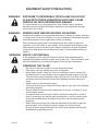
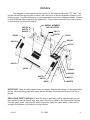
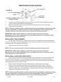
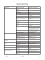
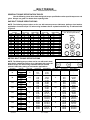
OPERATOR’S AND PARTS MANUAL HT52 / HT66 / HT78 HYDRAULIC TILLERS SERIAL NUMBER: ___________________ Manual Number: 51-10036 Part Number: MODEL NUMBER: ___________________ STD; 102000 or 100935 with MOTOR KIT D or E HF: 100935 or 103286 with MOTOR KIT H Rev. 5 800-456-7100 I www.paladinattachments.com 503 Gay Street, Delhi, IA 52223, United States of America Copyright © 11/4/13 TABLE OF CONTENTS PREFACE .......................................................................................................................................... 3 SAFETY PRECAUTIONS SAFETY STATEMENTS ........................................................................................................ 4 GENERAL SAFETY PRECAUTIONS ................................................................................ 4-6 EQUIPMENT SAFETY PRECAUTIONS.............................................................................. 7-8 DECALS DECAL PLACEMENT............................................................................................................. 9 DECALS.................................................................................................................................10 INSTALLATION.............................................................................................................................11-12 OPERATION................................................................................................................................. 13-17 BEFORE OPERATION OPERATING THE TILLER TINE ROTATION OPTIONAL SCARIFIER TEETH STORAGE TRANSPORTING LIFT POINTS TIE DOWN POINTS LUBRICATION....................................................................................................................................18 MAINTENANCE AND SERVICE.................................................................................................. 19-22 ROUTING MAINTENANCE CHAIN ADJUSTMENT REPLACING THE HYDRAULIC MOTOR REPLACING RIGHT BEARING ASSEMBLY REPLACING LEFT BEARING ASSEMBLY REPLACING TINE ASSEMBLY REPLACING CHAIN AND SPROCKETS TROUBLESHOOTING.......................................................................................................................23 SPECIFICATIONS ........................................................................................................................... 24 BOLT TORQUE SPECIFICATIONS...................................................................................................25 WARRANTY.......................................................................................................................................27 PARTS TILLER ASSEMBLY ....................................................................................................... 28-31 OPTIONAL SCARIFIER.........................................................................................................32 11/4/13 51-10036 1 THIS PAGE IS INTENTIONALLY BLANK 2 51-10036 11/4/13 PREFACE GENERAL COMMENTS Congratulations on the purchase of your new attachment! This product was carefully designed and manufactured to give you many years of dependable service. Only minor maintenance (such as cleaning and lubricating) is required to keep it in top working condition. Be sure to observe all maintenance procedures and safety precautions in this manual and on any safety decals located on the product and on any equipment on which the attachment is mounted. This manual has been designed to help you do a better, safer job. Read this manual carefully and become familiar with its contents. WARNING! Never let anyone operate this unit without reading the "Safety Precautions" and "Operating Instructions" sections of this manual. Always choose hard, level ground to park the vehicle on and set the brake so the unit cannot roll. Unless noted otherwise, right and left sides are determined from the operator’s control position when facing the attachment. NOTE: The illustrations and data used in this manual were current (according to the information available to us) at the time of printing, however, we reserve the right to redesign and change the attachment as may be necessary without notification. BEFORE OPERATION The primary responsibility for safety with this equipment falls to the operator. Make sure the equipment is operated only by trained individuals that have read and understand this manual. If there is any portion of this manual or function you do not understand, contact your local authorized dealer or the manufacturer to obtain further assistance. Keep this manual available for reference. Provide the manual to any new owners and/or operators. SAFETY ALERT SYMBOL This is the “Safety Alert Symbol” used by this industry. This symbol is used to warn of possible injury. Be sure to read all warnings carefully. They are included for your safety and for the safety of others working with you. SERVICE Use only manufacturer replacement parts. Substitute parts may not meet the required standards. Record the model and serial number of your unit on the cover of this manual. The parts department needs this information to insure that you receive the correct parts. SOUND AND VIBRATION Sound pressure levels and vibration data for this attachment are influenced by many different parameters: some items are listed below (not inclusive): • prime mover type, age, condition, with or without cab enclosure and configuration • operator training, behavior, stress level • job site organization, working material condition, environment Based on the uncertainty of the prime mover, operator, and job site, it is not possible to get precise machine and operator sound pressure levels or vibration levels for this attachment. NOTE: A list of all Paladin Patents can be found at http://www.paladinattachments.com/patents.asp. 11/4/13 51-10036 3 SAFETY STATEMENTS THIS SYMBOL BY ITSELF OR WITH A WARNING WORD THROUGHOUT THIS MANUAL IS USED TO CALL YOUR ATTENTION TO INSTRUCTIONS INVOLVING YOUR PERSONAL SAFETY OR THE SAFETY OF OTHERS. FAILURE TO FOLLOW THESE INSTRUCTIONS CAN RESULT IN INJURY OR DEATH. DANGER THIS SIGNAL WORD IS USED WHERE SERIOUS INJURY OR DEATH WILL RESULT IF THE INSTRUCTIONS ARE NOT FOLLOWED PROPERLY. WARNING THIS SIGNAL WORD IS USED WHERE SERIOUS INJURY OR DEATH COULD RESULT IF THE INSTRUCTIONS ARE NOT FOLLOWED PROPERLY. CAUTION NOTICE THIS SIGNAL WORD IS USED WHERE MINOR INJURY COULD RESULT IF THE INSTRUCTIONS ARE NOT FOLLOWED PROPERLY. NOTICE INDICATES A PROPERTY DAMAGE MESSAGE. GENERAL SAFETY PRECAUTIONS WARNING! READ MANUAL PRIOR TO INSTALLATION Improper installation, operation, or maintenance of this equipment could result in serious injury or death. Operators and maintenance personnel should read this manual, as well as all manuals related to this equipment and the prime mover thoroughly before beginning installation, operation, or maintenance. FOLLOW ALL SAFETY INSTRUCTIONS IN THIS MANUAL AND THE PRIME MOVER'S MANUAL(S). READ AND UNDERSTAND ALL SAFETY STATEMENTS Read all safety decals and safety statements in all manuals prior to operating or working on this equipment. Know and obey all OSHA regulations, local laws, and other professional guidelines for your operation. Know and follow good work practices when assembling, maintaining, repairing, mounting, removing, or operating this equipment. KNOW YOUR EQUIPMENT Know your equipment’s capabilities, dimensions and operations before operating. Visually inspect your equipment before you start, and never operate equipment that is not in proper working order with all safety devices intact. Check all hardware to ensure it is tight. Make certain that all locking pins, latches, and connection devices are properly installed and secured. Remove and replace any damaged, fatigued, or excessively worn parts. Make certain all safety decals are in place and are legible. Keep decals clean, and replace them if they become worn and hard to read. 4 51-10036 11/4/13 WARNING! GENERAL SAfETy PRECAUTIONS GENERAL SAFETY PRECAUTIONS PROTECT AGAINST fLyING DEbRIS wearFLYING proper safety glasses, goggles, or a face shield when driving pins in or WARNING! PROTECT always AGAINST DEBRIS out, or when any operation causes dust, flying debris, or any other hazardous mateAlways wear proper safety glasses, goggles or a face shield when driving pins in or rial. out, or when any operation causes dust, flying debris, or any other hazardous material. WARNING! LOWER ORRAISED SUPPORT RAISED EQUIPMENT WARNING! LOWER OR SUPPORT EQUIPMENT Do not work under raised booms withoutthem. supporting them. not use Do not work under raised booms without supporting Do not use Do support support mate- rialof made of concrete logs, buckets, or anymaterial other material that could material made concrete blocks,blocks, logs, buckets, barrelsbarrels, or any other that suddenly collapse shift positions. sure support material is solid, could suddenly collapse or shiftorpositions. MakeMake sure support material is solid, not not decayed,twisted, warped,ortwisted, or tapered. lowertobooms ground levelblocks. or on blocks. lower decayed, warped, tapered. Lower booms groundtolevel or onto booms and attachments to the ground before leaving the cab or operator’s station. Lower booms and attachments to the ground before leaving the cab or operator’s station. WARNING! USE CARE WITH HyDRAULIC fLUID PRESSURE WARNING! USE CAREHydraulic WITH HYDRAULIC FLUIDcan PRESSURE fluid under pressure penetrate the skin and cause serious injury or Hydraulic fluid under pressure can under penetrate the skin and serious injuryconnecting or death. hydraulic leaks pressure may notcause be visible. before or dis- death. Hydraulic leaks hydraulic under pressure be prime visible. Beforeoperator’s connecting or for detailed connecting hoses,may readnot your mover’s manual disconnecting hydraulic hoses, read your prime movers operator’s manual for detailed instructions on connecting and disconnecting hydraulic hoses or fittings. instructions on connecting and disconnecting hydraulic hoses or fittings. • Keep unprotected body parts, such as face, eyes, and arms as far away as • Keep unprotected body such as leak. face, Flesh eyes, injected and arms as hydraulic far away as possible fromparts, a suspected with fluid may develop possible from a suspected leak. Flesh injected with hydraulic fluid may develop gangrene or other permanent disabilities. gangrene or other permanent disabilities. • If injured by injected fluid, see a doctor at once. If your doctor is not familiar with • If injured by injected fluid, see a doctor at once. If your doctor is not familiar with this type of injury, ask him to research it immediately to determine proper treat this type of injury, ask him to research immediately to determine proper treatment. ment. • Wear safety glasses, protective clothing, and use a sound piece of cardboard or • Wear safety glasses, protective clothing, and use a piece of cardboard or wood wood when searching for hydraulic leaks. DO NOT USE YOUR HANDS! when searching for hydraulic leaks. DO NOT USE yOUR HANDS! SEE ILLUSTRATION. SEE ILLUSTRATION. CARDbOARD HyDRAULIC HOSE OR fITTING MAGNIfyING GLASS 4 11/4/13 51-10036 5 76288 GENERAL SAFETY PRECAUTIONS WARNING! DO NOT MODIFY MACHINE OR ATTACHMENTS Modifications may weaken the integrity of the attachment and may impair the function, safety, life, and performance of the attachment. When making repairs, use only the manufacturer’s genuine parts, following authorized instructions. Other parts may be substandard in fit and quality. Never modify any ROPS (Roll Over Protection Structure) or FOPS (Falling Object Protective Structure) equipment or device. Any modifications must be authorized in writing by the manufacturer. WARNING! SAFELY MAINTAIN AND REPAIR EQUIPMENT • Do not wear loose clothing, or any accessories that can catch in moving parts. • • • • If you have long hair, cover or secure it so that it does not become entangled in the equipment. Work on a level surface in a well-lit area. Use properly grounded electrical outlets and tools. Use the correct tool for the job at hand. Make sure they are in good condition for the task required. Wear the protective equipment specified by the tool manufacturer. WARNING! SAFELY OPERATE EQUIPMENT Do not operate equipment until you are completely trained by a qualified operator in how to use the controls, know its capabilities, dimensions, and all safety requirements. See your machine's manual for these instructions. • Keep all step plates, grab bars, pedals, and controls free of dirt, grease, debris, and oil. • Never allow anyone to be around the equipment when it is operating. • Do not allow riders on the attachment or the prime mover. • Do not operate the equipment from anywhere other than the correct operators position. • Never leave equipment unattended with the engine running or with this attachment in a raised position. • Do not alter or remove any safety feature from the prime mover or this attachment. • Know your work site safety rules as well as traffic rules and flow. When in doubt on any safety issue, contact your supervisor or safety coordinator for an explanation. WARNING! KNOW WHERE UTILITIES ARE Observe overhead electrical and other utility lines. Be sure equipment will clear them. 6 When digging, call your local utilities for location of buried utility lines, gas, water, and sewer, as well as any other hazard you may encounter. 51-10036 11/4/13 EQUIPMENT SAFETY PRECAUTIONS WARNING! EXPOSURE TO RESPIRABLE CRYSTALLINE SILICA DUST ALONG WITH OTHER HAZARDOUS DUSTS MAY CAUSE SERIOUS OR FATAL RESPIRATORY DISEASE. It is recommended to use dust suppression, dust collection and if necessary personal protective equipment during the operation of any attachment that may cause high levels of dust. WARNING! REMOVE PAINT BEFORE WELDING OR HEATING Hazardous fumes/dust can be generated when paint is heated by welding, soldering or using a torch. Do all work outside or in a well ventilated area and dispose of paint and solvent properly. Remove paint before welding or heating. When sanding or grinding paint, avoid breathing the dust. Wear an approved respirator. If you use solvent or paint stripper, remove stripper with soap and water before welding. Remove solvent or paint stripper containers and other flammable material from area. Allow fumes to disperse at least 15 minutes before welding or heating. WARNING! END OF LIFE DISPOSAL At the completion of the useful life of the unit, drain all fluids and dismantle by separating the different materials (rubber, steel, plastic, etc.). Follow all federal, state and local regulations for recycling and disposal of the fluid and components. OPERATING THE TILLER • • • • • • • • • 11/4/13 Stay clear of tiller when engine is running. Keep others away. Keep hands, feet and clothing away from moving parts. Never allow anyone to reach into, kick into or otherwise come in contact with the rotating tines. Do not attempt to clear clogged tines while engine is running. Tines can crush and/or dismember. Keep everyone clear of the tiller until proper shut down procedure has been followed and hydraulic pressure has been relieved. Operate only from the operator’s station. To prevent serious injury or death from thrown objects, stay away from discharge area during operation. Reduce speed when driving over rough terrain, on a slope, or turning, to avoid overturning the vehicle. An operator must not use drugs or alcohol, which can change his or her alertness or coordination. An operator taking prescription or over-the-counter drugs should seek medical advice on whether or not he or she can safely operate equipment. Before exiting the prime mover, lower the attachment to the ground, apply the parking brakes, turn off the prime mover’s engine, and remove the key. Be sure all doors, guards and shields are in their proper position and securely attached before operating the tiller. 51-10036 7 EQUIPMENT SAFETY PRECAUTIONS TRANSPORTING THE TILLER • • • • Travel only with the attachment in a safe transport position to prevent uncontrolled movement. Drive slowly over rough ground and on slopes. When driving on public roads use safety lights, reflectors, Slow Moving Vehicle signs etc., to prevent accidents. Check local government regulations that may affect you. Do not smoke when refueling the prime mover. Allow room in the fuel tank for expansion. Wipe up any spilled fuel. Secure cap tightly when done. When transporting on a trailer: Secure attachment at recommended tie down locations using tie down accessories that are capable of maintaining attachment stability. MAINTAINING THE TILLER • • • • • 11/4/13 Before performing maintenance, lower the attachment to the ground, apply the parking brakes, turn off the prime mover’s engine, and remove the key. Never perform any work on the attachment unless you are authorized and qualified to do so. Always read the operator service manual’s before any repair is made. After completing maintenance or repair, check for correct functioning of the attachment. If not functioning properly, always tag “DO NOT OPERATE” until all problems are corrected. Worn, damaged, or illegible safety decals must be replaced. New safety decals can be ordered from Paladin. Never make hydraulic repairs while the system is under pressure. Serious personal injury or death could result. Never work under a raised attachment. 51-10036 8 DECALS DECAL PLACEMENT GENERAL INFORMATION DECALS The diagram on this page shows the location of the decals used on the The diagram onThe thisdecals page shows the location of the usedwith on the FFC Tiller. The BRADCO Tiller. are identified by their partdecals numbers, reductions decalsofare identified by their part numbers, with reductions of the actual decals the actual decals located on the following pages. Use this information tolocated order on the following page. Usefor this information to order replacements for lost or damaged replacements lost or damaged decals. Be sure to read all decals beforedecals. Be sure to read all decals the information attachment.you They contain information nee to know operating thebefore tiller. operating They contain need to know for both you safety for both safety and product longevity. and tiller longevity. SERIAL NUMBER #40795 TAG LOCATION #40796 #40113 #40829 #40798 #4085 #4338 #40440 #40161 #40150 #4235 #4105 #4495 #40590 #4235 #40161 #4085 #40151 #40678 IMPORTANT: Keep all safety signs clean and legible. Replace all missing, illegible, or damaged safety signs. When replacing parts with safety signs atIMPORTANT: Keep all safety clean legible. Replace all missing, or damaged safety tached, the safety signs decals must also be and replaced. decals. When replacing parts with safety decals attached, the safety decals must also be replaced. REPLACING SAFETY SIGNS: Clean the area of application with nonflammable solvent, then wash the same area with soap and water. Allow the surface to fully REPLACING SAFETY DECALS: Clean the area of application with a nonflammable dry. Remove the backing from the safety sign, exposing the adhesive surface. solvent, then wash soap and water. Allow thediagram surfaceabove to dry.and Remove theout backing Applythe thesame safetyarea signwith to the position shown in the smooth from the safety decal, exposing the adhesive surface. Apply the safety decal to the position any bubbles. 9881 shown in the diagram, and smooth out any bubbles. 11-2-04 11/4/13 51-10036 9 NGER STAND CLEAR ITEM QTY PART NO. * * 40161 DECALS D CLEAR ND CLEAR MADE IN U.S.A. PART #4338 PART NO. MADE 40440IN U.S.A. PART #40161 STAND CLEAR PART #40150 WARNING! READ MANUAL PART #40151 TOLERANCE WARNING! HIGH DECIMAL PRESSURE FLUID T52 HT52 T66 HT52 HT52 HT66 HT66 HT66 HT78 T78 HT78 HT78 Q .XX +/-.06 .XXX +/-.030 .XXXX +/-.0100 ANGULAR +/-1 DEG. UNLESS OTHERWISE SPECIFIED DECALS DANGER STAND CLEAR DECALS Q PART #4105 DANGER! STAND CLEAR Q F E D C B A REV. VENDOR: POC: DARYL TABBERT REF. NO. **** Q DRAWN LLS RELEASE FOR PRODUCTION DESCRIPTION DATE Q PART #4495 PART #40590 WARNING! GUARD REMOVED MADE IN U.S.A. PART #4105 DANGER! STAND CLEAR PART #40161 STAND CLEAR UMBER PART #4105 DANGER! STAND CLEAR PART #40161 STAND CLEAR TITLE: DECAL, STAND CLEAR THIS DRAWING & ALL INFORMATION THEREON IS PROPERTY OF BRADCO /MCMILLEN/THE MAJOR, AND MUST NOT BE USED IN ANY WAY WITHOUT CONSENT OR IN ANY WAY DETRIMENTAL TO THE INTERESTS OF BMCMM. DANGER STAND CLEAR DECALS STAND CLEAR CAUTION! DO NOT USE HI-FLOW PART #40440 DANGER STAND CLEAR CALL BEFORE YOU DIG STAND CLEAR Q CREATIVE SCREEN PRINT INC. P.O. BOX 867 602 COMMERCE DRIVE WEST SALEM, WISCONSIN 54669 PHONE: 608-786-3370 FAX: 608-786-2807 FIRST USE PRODUCT: 615 TRENCHER DATE6 2-12-07 MAT’L: PART #40678 LKS CHECKED DATE SCALE NONE WARNING! BEFORE LEAVING BY 3690 3M DECAL DO NOT SCALE DWG. DEBURR PART PART #4338 MADE IN U.S.A. MADE IN U.S.A. PART #4338 MADE IN U.S.A. ** FIRST USED MADE IN U.S.A. TITLE: DECAL,CALL BEFORE YOU DIG PART #4338 MADE IN U.S.A. STAND CLEAR SIZE = 2.00” X 4.00” PART #40113 BRADCO LOGO THIS DRAWING & ALL INFORMATION THEREON IS PROPERTY PART #40161 OF BRADCO /MCMILLEN/THE MAJOR, AND MUST NOT BE USEDSTAND IN ANY WAY WITHOUT CONSENT OR IN ANY WAY CLEAR DETRIMENTAL TO THE INTERESTS OF BMCMM. DRAWN DATE PART #40113 LLS BRADCO 11/9/07 LOGO CHECKED DATE BY LLS #40113 ITEM PART PARTQTY #40795 * UMBER DATE FIRST USE PRODUCT: ITEM PART NO. PART #40795 * 4235 HT52 MODEL NUMBER PART #40798 CAUTION! SCARIFIER TEETH CONTACT 40440 PART NO. PART #40795 HT52 MODEL NUMBER PART #4105 DANGER! STAND CLEAR PART #4085 PART #4495 GREASE 40 HOURS WARNING! GUARD REMOVED PART #4085 GREASE 40 HOURS PART #40796 HT66 MODEL NUMBER PART #40796 HT66 MODEL NUMBER PART #40796 HT66 MODEL NUMBER PART #40838 HT78 MODEL NUMBER PART #40838 HT78 MODEL NUMBER PART #40829 HT78 MODEL NUMBER PART #40838 HT78 MODEL NUMBER TOLERANCE DECIMAL .XX +/-.06 .XXX +/-.030 .XXXX +/-.0100 ANGULAR +/-1 DEG. UNLESS OTHERWISE SPECIFIED 4235 PART #4495 WARNING! GUARD REMOVED HT66 MODEL NUMBER PART #4085 GREASE 40 HOURS PART #40678 WARNING! BEFORE LEAVING OPERATOR'S SEAT PART #40678 WARNING! BEFORE LEAVING PART #40678 OPERATOR'S 9883SEAT WARNING! BEFORE LEAVING OPERATOR'S SEAT 11-2-04 PART #40678 9883 WARNING! BEFORE LEAVING OPERATOR'S SEAT 11-2-04 TOLERANCE DECIMAL .XX +/-.06 .XXX +/-.030 .XXXX +/-.0100 ANGULAR +/-1 DEG. UNLESS OTHERWISE SPECIFIED 9883 11-2-04 PART #4495 WARNING! GUARD REMOVED 9883 11-2-04 VENDOR: PART #4235 WARNING! MOVING PADDLES 10 F E PART #4085 HOURS GREASE 40 HOURS BRADCO LOGO HT52 MODEL NUMBER PART #40795 HT52 PARTMODEL #40796NUMBER UMBER PART #4085 QTY GREASE PART NO. 40 MAT’L: 3690 3M DECAL * * 4495 SCALE DO NOT SCALE DWG. PART NO. PART #4495 DEBURR PART NONE WARNING! GUARD REMOVED REF. NO. **** F E D C B POC: DARYL TABBERT REF. NO. **** SIZE = 3.50” X 6.00” CREATIVE SCREEN PRINT INC. P.O. BOX 867 602 COMMERCE DRIVE WEST SALEM, WISCONSIN 54669 PHONE: 608-786-3370 FAX: 608-786-2807 51-10036 THIS DRAWING & ALL INFORMATION THEREON IS PROPERTY OF BRADCO /MCMILLEN/THE MAJOR, AND MUST NOT BE USED IN ANY WAY WITHOUT CONSENT OR IN ANY WAY THIS DRAWING & ALL INFORMATION THEREON IS PROPERTY OF BRADCO /MCMILLEN/THE MAJOR, AND MUST NOT BE USED IN ANY WAY WITHOUT CONSENT OR IN* ANY * WAY DETRIMENTAL TO THE INTERESTS OF BMCMM. FIRST USED DRAWN DATE6 TITLE: DECAL, LLS WARNING, MOVING PADDLES 2-12-07 LKS CHECKED DATE TITLE: DECAL, 11/4/13 WARNING, GUARD FIRST USE PRODUCT: MAT’L: 3690 3M DECAL INSTALLATION GENERAL INFORMATION The FFC Tillers covered in this manual were designed to be used on various prime movers with various different horsepower, operating capacities and lifting capacities. Before installing the attachment you have received onto your prime mover, verify that your attachment is compatible with your prime mover. Check to be certain each unit is within the limitations of the other. Operating the attachment on a prime mover that exceeds any of the recommended specifications will cause damage to the attachment and void all warranties. NOTE: The chain driven tiller is available with various motor options (Standard and High Flow) to adapt the GPM of the tiller to the GPM of the prime mover. Check to ensure that the tiller is equipped with the correct motor for your prime mover application. INSTALLATION Install the attachment by following your power units operator’s manual for installing an attachment. NOTE: The HT66 and HT78 tillers are designed for center or offset mounting which will allow the right tracks to be covered as the prime mover travels in reverse during finish tilling operation. WARNING! To avoid serious personal injury, make sure the attachment is securely latched to the attachment mechanism of your unit. Failure to do so could result in separation of the attachment from the prime mover. If installing a high flow tiller onto your prime mover, install the case drain hose and coupler onto your attachment. NOTE: The case drain line (if so equipped) must be connected first, then the power and return hoses. When disconnecting the hoses, it is recommended to disconnect the case drain line last. NOTICE: Be sure the case drain coupler is complete engaged. Immediate hydraulic motor seal failure will occur if case drain is not successfully connected. With the auxiliary hydraulic system turned off, route the hydraulic hoses over tiller housing in such a fashion as to avoid pinching and chafing of the hoses and connect them to their proper auxiliary couplers on the loader. Carefully raise the loader and cycle the tilt cylinders to check clearances and to verify that all mounting procedures have been successfully completed. Check for proper assembly, installation and hydraulic leaks. WARNING! Do not operate a standard flow tiller on a high flow hydraulic system or a high flow tiller on a standard flow hydraulic system. Serious injury or equipment damage may occur. 11/4/13 51-10036 11 INSTALLATION DETACHING On firm level ground, lower the loader arms until the attachment is on the ground. Turn off the engine. Move control levers back and forth to relieve pressure in the line. Disconnect couplers. NOTE: If disconnecting a high flow tiller it is recommended to disconnect the case drain line last. NOTE: Seal hydraulic system from contaminants and secure all hydraulic hoses off the ground to help prevent damage. Follow your prime mover’s operator’s manual for detaching (removing) an attachment. NOTE: Lubrication of the grease fittings on the bearing assembly at both ends of the shaft on the chain driven tillers will greatly increase the life of the product. 12 51-10036 11/4/13 OPERATION INTENDED USE: This unit is designed to cultivate soil for planting or landscaping. Use in any other way is considered contrary to the intended use. The FFC tillers are perfect for home gardening, landscaping, and vegetable farming. It turns up hard packed ground, and leaves the perfect seedbed for gardens and lawns. Simplicity of operation is one of the key features of the tiller. It is important, however, to be familiar with and know the controls and adjustments on both the tiller and prime mover. Such knowledge is crucial for safe, efficient operation of the equipment. Take the time to learn how they operate. PRIME MOVER The tiller mounts to the attachment mechanism of your prime mover. Due to this arrangement thorough knowledge of the prime mover controls is necessary. Read the prime mover operator’s manual for information regarding operation before attempting to use this attachment. Due to the various motor options available for the chain driven tiller, both standard and high flow, verify that the GPM of the tiller is compatible with the GPM of the prime mover before operating. NOTE: There is only one motor option on the Case/New Holland Tillers. BEFORE OPERATION • Clear the work area of all bystanders, pets, and livestock. • Know the job site. Take notice of any water or gas shut off, stumps, sidewalk edges etc., that the lowered tiller could come into contact with. • Be sure all tiller tines, bolts and nuts are tight and chain guards are in place. • Clear the area of rocks, branches and other foreign objects. • Tall grass and weeds may need to be mowed before tilling to avoid wrapping around the tine assembly, therefore reducing the tiller performance. • Adjust the left and right skid shoes (is so equipped) to the correct location for the desired tilling depth. DANGER! ROTATING TINES HAZARD! To prevent serious injury or death from rotating tines: Stay clear of tiller when engine is running. Keep others away. Keep hands, feet and clothing away from moving parts. Follow Safety Shutdown Procedure whenever leaving operator’s station. DANGER! THROWN OBJECT HAZARD! To Prevent serious injury or death from thrown objects: Stay away from discharge area during operation. Keep others away. OPERATING THE TILLER The main purpose of the tiller is to cultivate soil. The skid steer loader tillers are bi-directional and will operate with the tines rotating in either direction. After thoroughly checking the Tiller and preparing the work area you are ready to begin tilling. 11/4/13 51-10036 13 OPERATION TINE ROTATION The FFC Tiller can be operated while traveling in forward or reverse and the tines rotating in either direction. Although standard direction of rotation is for the tines to rotate in the same direction the prime-mover is traveling, reversing the tine rotation has been noted to bury debris better. STANDARD ROTATION: When you are traveling in the same direction that the tines are rotating. REVERSE ROTATION: When you are traveling in the opposite direction than the tines are rotating. REVERSE TINE ROTATION STANDARD TINE ROTATION DIRECTION OF TRAVEL DIRECTION OF TRAVEL DIRECTION OF TRAVEL DIRECTION OF TRAVEL RECOMMENDED FOR FINISH TILLING After thoroughly checking the tiller and preparing the work area you are ready to begin tilling. Although the performance of the tiller can vary significantly depending upon the way it is used, we recommend the following operating procedure for maximum productivity. 1. 2. 3. 4. Following the prime mover manuals operating and safety procedures, start the prime mover and position the tiller at the starting location. With the prime mover at idle speed, position the tiller with the loader arms fully back and lowered. Engage auxiliary hydraulics to begin tiller rotation. Increase engine RPM. (Tines will cut better at full RPM.) Carefully lower the tiller to the ground and begin to slowly travel in the desired direction. Gradually increase engine RPM until the desired results are achieved. CAUTION! Be prepared for sudden prime mover movement when lowering the tiller into the ground. Rotating tines are capable of pulling or pushing the prime mover, depending on tine rotation. NOTE: It is recommended after the first 50 feet to stop and check tiller depth. For finish tilling, it is recommended the tiller be operated while driving in reverse with the tines rotating in a clockwise direction when viewed from the left side of the machine (standard rotation for reverse travel). This will allow the tracks to be covered as the prime mover moves in reverse, finishing the tilling operation. 14 51-10036 11/4/13 OPERATION Tilling should not be done in wet conditions, as soil will stick to the tines. There is also several conditions that will cause the tiller to “walk up” onto the top of the ground and either push or pull the prime mover. The most common of these conditions is traveling too fast and low engine RPM (tines moving too slowly for ground conditions). If you have increased the engine RPM and decreased travel speed and the tiller continues to “ walk up” check the tines to make sure the cutting edge is still sharp and all tines are intact. OPTIONAL SCARIFIER TEETH The optional scarifier teeth are used in front of the tiller tines to dig into and loosen the soil, therefore increasing the efficiency of the hydraulic horsepower available for tilling. The teeth can be used when traveling in forward or reverse direction by switching the direction of the teeth. When traveling in reverse, use the scarifiers and the tiller in the same pass. When traveling forward rotate the tiller up with the scarifiers digging into the ground to loosen hard, packed soil and then return to the starting point to start the tilling operation. The scarifier teeth can be lifted up and stored on the unit when not in use. TRAVEL IN THE FORWARD DIRECTION WITH THE TILLER ROTATED UP AND THE SCARIFIER TEETH DIGGING INTO THE SOIL TRAVEL IN REVERSE WITH THE SCARIFIER TEETH DIGGING INTO THE SOIL FOLLOWED BY THE ROTATING TINES. DIRECTION OF TRAVEL SCARIFIERS 11/4/13 51-10036 SCARIFIERS 15 OPERATION The following procedure will help you to keep your unit in top condition. It will also help you get off to a good start the next time your tiller is needed. We therefore strongly recommend that you take the extra time to follow this procedure whenever your tiller will not be used for and extended period of time. PREPARATION FOR STORAGE • Clean the unit thoroughly, removing all mud, dirt and grease. • Inspect for visible signs of wear, breakage or damage. Inspect the tines for wear. Order any parts required and make the necessary repairs to avoid delays when starting next season. NOTE: Purchase only approved parts from your authorized dealer. When replacing tines it is recommended that you replace mounting hardware also. • Tighten all loose nuts, bolts and hydraulic connections. • Connect the hydraulic couplers together or cap them to protect the hydraulic system from contaminates. • Replace decals if damaged or in unreadable condition. • Grease all grease fittings (if so equipped). • Seal hydraulic system from contaminants and secure all hydraulic hoses off the ground to help prevent damage. • Store the unit in a dry and protected place. Leaving the machine outside will materially shorten its life. Additional Precautions for Long Term Storage: • Touch up all unpainted and exposed areas with paint to prevent rust. REMOVAL FROM STORAGE • Remove all protective coverings. • Check hydraulic hoses for deterioration and replace if necessary. • Check all nuts, bolts and hydraulic connections for tightness. TRANSPORTING • Follow all federal, state and local regulations when transporting on public roads. • Use extra care when loading and unloading onto a trailer or truck. Disconnect hydraulic couplers during transport. CAUTION! Be sure to install a SMV (Slow Moving Vehicle) sign on loader before transporting. When transporting on a road or highway at night or during the day, use accessory lights and devices for adequate warning to the operators of other vehicles. In this regard, check local and government regulations. Always drive slowly over uneven terrain to avoid tipping the unit. 16 51-10036 11/4/13 OPERATION LIFT POINTS Lifting points are identified by lifting decals where required. Lifting at other points is unsafe and can damage attachment. Do not attach lifting accessories around cylinders or in any way that may damage hoses or hydraulic components. • • • Attach lifting accessories to unit at recommended lifting points. Bring lifting accessories together to a central lifting point. Lift gradually, maintaining the equilibrium of the unit. WARNING! Use lifting accessories (chains, slings, ropes, shackles and etc.) that are capable of supporting the size and weight of your attachment. Secure all lifting accessories in such a way to prevent unintended disengagement. Failure to do so could result in the attachment falling and causing serious personal injury or death. TIE DOWN POINTS Tie down points are identified by tie down decals where required. Securing to trailer at other points is unsafe and can damage attachment. Do not attach tie down accessories around cylinders or in any way that may damage hoses or hydraulic components. • • Attach tie down accessories to unit as recommended. Check unit stability before transporting. WARNING! Verify that all tie down accessories (chains, slings, ropes, shackles and etc.) are capable of maintaining attachment stability during transporting and are attached in such a way to prevent unintended disengagement or shifting of the unit. Failure to do so could result in serious personal injury or death. 17 11/4/13 51-10036 H H LUBRICATION LUBRICATION GENERAL INFORMATION GENERAL INFORMATION Economical and efficient operation of any machine is dependent upon Economical efficient operation machine is dependent uponlubricant. regular and proper regular and and proper lubrication of of allany moving parts with a quality Neglect lubrication of to all reduced moving parts with a quality Neglect leads to reduced efficiency, wear, leads efficiency, wear, lubricant. breakdown and needless replacement of parts. breakdown and needless replacement of parts. All parts provided with grease fittings should be lubricated, as indicated. If any All parts provided with grease fittings should be lubricated, as indicated. If any grease fittings grease fittings are missing, replace them immediately. Clean all fittings thoroughly are missing, replace them immediately. Clean all fittings thoroughly before using the grease gun. before using the grease gun. IMPORTANT: Avoid excessive greasing. Dirt collects on exposed and greatlyand IMPORTANT: Avoid excessive greasing. Dirt collects on grease exposed grease increases wear. After greasing, wipe off excessive grease from fittings. greatly increases wear. After greasing, wipe off excessive grease from fittings. LUBRICATION SYMBOLS LUBRICATION SYMBOLS The following symbols are used on lubrication diagram below.diagram It is reproduced The following symbols aretheused on the lubrication below. here It iswith its meaning for your convenience. reproduced here with its meaning for your convenience. 40 Lubricate weekly or every 40 hours of operation, whichever comes last, with SAE Multi-Purpose Lubricant or equivalent SAE Multi-Purpose type grease. Lubricate drive chain periodically with a chain lubricant CAUTION! SHUT OFF ENGINE BEFORE LUBRICATING EQUIPMENT. BEARING ASSEMBLY (BOTH ENDS OF SHAFT) 40 DRIVE CHAIN 40 BEARING ASSEMBLY (BOTH ENDS OF SHAFT) 18 51-10036 9872 11/4/13 11-8-04 MAINTENANCE AND SERVICE GENERAL INFORMATION Regular maintenance is the key to long equipment life and safe operation. Maintenance requirements have been reduced to the absolute minimum. However, it is very important that these maintenance functions be performed as described below. Procedure Check all bolts and nuts for tightness. Replace any missing bolts or nuts with approved replacement parts. Check hydraulic system for hydraulic oil leaks. See procedure below. Visually inspect the machine for worn parts or cracked welds, and repair as necessary. Check all guards are securely in place. Lubricate all grease fittings. Adjust and lubricate drive chain (if so equipped). To lubricate drive chain: remove chain cover and spray a chain lubricant along the drive chain. Daily Every 40 Hours NOTE: Avoid using a high pressure pneumatic lubricating equipment on the tiller shaft bearings. These bearings are assembled with special high dirt exclusion seals. High pressure lubricating equipment can damage the seals. WARNING! Do not operate the tiller during maintenance or while any guards are removed. WARNING! Escaping fluid under pressure can have sufficient force to penetrate the skin, causing serious personal injury. Fluid escaping from a very small hole can be almost invisible. Use a piece of cardboard or wood, rather than hands, to search for suspected leaks. Keep unprotected body parts, such as face, eyes, and arms as far away as possible from a suspected leak. Flesh injected with hydraulic fluid may develop gangrene or other permanent disabilities. If injured by injected fluid, see a doctor at once. If your doctor is not familiar with this type of injury, ask him to research it immediately to determine proper treatment. 11/4/13 51-10036 19 MAINTENANCE AND SERVICE CHAIN ADJUSTMENT We recommend adjusting the chain after the initial 4 hours and then monthly thereafter. TO ADJUST THE CHAIN: Remove the chain cover and loosen the two bolts on the motor mounting adjustment plate and the one bolt on the cam lock. Insert a 1/2" ratchet into the cam lock and rotate until the chain is tight. (A properly adjusted chain will have a minimal amount of chain deflection. Over tensioning will cause premature wear.) NOTE: If all of the cam lock adjustment is used and the chain and sprocket are still serviceable you can remove a "half link" from the chain at the master link location. If replacing the chain it is recommended to replace the sprockets at the same time. REPLACING THE HYDRAULIC MOTOR L MAINTENANCE & SERVICE Set the tiller on the ground and place supports under the assembly to REPLACING THEweight HYDRAULIC MOTOR keep the of the unit off of the tines. Set the Tiller on the ground and place supports under the assembly to keep the weight of the Avoid serious injury. Follow Safety Shutdown procedures unit off ofWARNING! the tines. before performing maintenance or service. WARNING! Avoid serious injury. Follow Safety Shutdown procedures before performing Remove theorchain guard on the left side of the tiller. NOTE: It is recom 1. maintenance service. mended that you loosen the chain tension by loosening cam tension. 1. 2. 3. 4. 5. 2. Remove the top sprocket from the hydraulic motor by loosening the two Remove the chain guard on the left side of the Tiller. NOTE: It is recommended that you set screws and sliding off of the motor shaft. loosen the chain tension by loosening cam tension. 3. Tag and disconnect the hydraulic hydraulicmotor hoses fittingsthe from Remove the top sprocket from the byand loosening twothe set hydraulic screws and sliding off of the motor. motor shaft. Tag and disconnect the hydraulic hoses and fittings from the hydraulic motor. 4. Remove the three bolts securing the motor adjustment plate and then Remove the three bolts securing the motor adjustment plate and then either loosen or remove either loosen or remove the cam from the tiller housing. See Figure #1 the cam from the Tiller housing. See Figure #1. 5. Remove the boltsthe securing the motorplate. adjustment plate. Remove the bolts securing motor tothe themotor motor to adjustment See Figure #1.See Figure #1 MOTOR MOUNTING CAPSCREWS FIGURE #1 ADJUSTMENT PLATE MOUNTING BOLTS HYDRAULIC MOTOR CAM CAM MOUNTING BOLT 6. 7. 8. 9. 20 TOP SPROCKET Install new hydraulic motor to the motor usingplate the existing hardware. 6. theInstall the new hydraulic motor to plate the motor using the existing hardware. Reconnect the hydraulic hoses and fittings to the new motor in the same orientation and in the 7. Reconnect the hydraulic hoses and fittings to the new motor in the same same port as previously installed. orientation thehousing same port asthe previously installed. Loosely install the cam to Bolt the motor plate toand thein Tiller using existing hardware. the housing. 8. Tiller Bolt the motor plate to the tiller housing using the existing hardware. Place theLoosely drive chain overthe thecam top sprocket andhousing. install the sprocket onto the new hydraulic install to the tiller motor. Tighten sprocket set screws. 9. Place the drive chain over the top sprocket and install the sprocket onto the new hydraulic motor. Tighten sprocket set screws. NOTE: Align the top sprocket with51-10036 the bottom sprocket using a straight edge. Failure to align the two sprockets with each other will cause excessive wear to the chain and sprockets. 11/4/13 L MAINTENANCE AND SERVICE NOTE: Align the top sprocket with the bottom sprocket using a straight edge. Failure to align the two sprockets with each other will cause excessive wear to the chain and sprockets. 10. Tighten the cam to the housing and following the chain adjustment instructions on the previous page, tighten the chain. L L 11. Install the chain cover to the Tiller. MAINTENANCE & SERVICE NOTE: Field replacement of internal motor seals voids warranty. NOTE: Field replacement of internal motor seals voids warranty. IMPORTANT: When replacing parts use only factory approved replacement parts. IMPORTANT: parts use onlyof factory approved replacement parts.and/or Manufacturer will notWhen claimreplacing responsibility for use unapproved parts or accessories Manufacturer will not responsibility for use of unapproved parts or accesother damages as a result ofclaim their use. sories and/or other damages as a result of their use. REPLACING RIGHT ASSEMBLY REPLACING RIGHTBEARING BEARING ASSEMBLY Set the Tiller on the ground and place supports under the assembly to keep the weight of the Set the on the ground and place supports under the assembly to keep the unit off of the tines andtiller shaft. weight of the unit off of the tines and shaft. 1. Remove the shaft right side of side the housing if used. See SeeFigure Figure#2 #2. 1. Remove thecover shaftfrom coverthe from the right of the housing. 2. Remove the set screws holding the bearing locking collar in place and remove the bearing 2. Remove the set screws holding the bearing locking collar in place and remove the assembly. See Figure #2. bearing assembly. See Figure #2 SIDE CUTTER PLATE FIGURE #2 .62" LOCK NUTS .62" x 2.25" CAPSCREWS SHAFT SHAFT COVER BEARING ASSEMBLY WITH LOCKING COLLAR 3. Position thebearing new bearing assembly over shaft. the shaft and tighten 3. Position the new assembly over shaft. InstallInstall the shaft covercover if used and tighten all all hardware. Secure theassembly bearing assembly to the shaft thecollar locking collar with hardware. Secure the bearing to the shaft using the using locking provided the bearing. provided with the bearing. REPLACING LEFT BEARING ASSEMBLY REPLACING LEFT BEARING ASSEMBLY theon tiller the ground and supports place supports under the assembly keep Set theSet Tiller theon ground and place under the assembly to keeptothe weight of the the weight of the unit off of the tines and shaft. unit off of the tines and shaft. 1. Remove the chain guard on the left side of the tiller. NOTE: It is recommended 1. Remove theyou chain guardthe on chain the lefttension side of the Tiller. NOTE: is recommended that you that loosen by loosening camIttension. loosen the chain tension by loosening cam tension. 2. Remove the bottom sprocket from the shaft by loosening the two set screws and 2. Remove the bottom sprocket from the shaft by loosening the two set screws and sliding off sliding off the sprocket and chain. See Figure #3 the sprocket and chain. See Figure #3. 3. the bearing from the loosen housing, twosecuring setscrews 3. UnboltUnbolt the bearing assemblyassembly from the housing, the loosen two set the screws the securing the remove assembly tobearing the shaftassembly. and remove theFigure bearing assembly. See Figure assembly to the shaft and the See #3. #3 FIGURE #3 11/4/13.62" x 2.25" CAPSCREWS SHAFT .62" LOCK NUTS 21 51-10036 BOTTOM that you loosen the chain tension by loosening cam tension. 2. Remove the bottom sprocket from the shaft by loosening the two set screws and sliding off the sprocket and chain. See Figure #3 3. Unbolt the bearing assembly from the housing, loosen the two setscrews MAINTENANCE AND securing the assembly to the shaft and remove theSERVICE bearing assembly. See Figure #3 .62" LOCK NUTS FIGURE #3 .62" x 2.25" CAPSCREWS SHAFT BOTTOM SPROCKET BEARING ASSEMBLY WITH LOCKING COLLAR 4. 5. 9875 11-1-04 Position the new bearing assembly and secure in place with the existing hardware and then with the locking collar included with the assembly. Place the drive chain over the bottom sprocket and install the sprocket onto the shaft. Tighten sprocket set screws. NOTE: Bottom sprocket should be installed against the bearing assembly and the top sprocket adjusted to align with it. Align the sprockets using a straight edge. Failure to align the two sprockets with each other will cause excessive wear to the chain and sprockets. IMPORTANT: When replacing parts use only factory approved replacement parts. Manufacturer will not claim responsibility for use of unapproved parts or accessories and/or other damages as a result of their use. REPLACING TINE ASSEMBLY Set the Tiller on the ground in a location where a hoist is available and remove the attachment from your prime mover. Securely attach a hoist to the front portion of the Tiller and rotate the Tiller until it is resting on the quick-attach mounting plate. 1. Inspect all tines and replace as needed. NOTE: Be sure to install new tines in the same direction as the tine being removed. IMPORTANT: When replacing parts use only factory approved replacement parts. Manufacturer will not claim responsibility for use of unapproved parts or accessories and/or other damages as a result of their use. REPLACING CHAIN AND SPROCKETS Set the Tiller on the ground and place supports under the assembly to keep the weight of the unit off of the tines and shaft. It is recommended that the sprockets and chain be replaced at the same time. A worn chain will adversely affect the service life of the sprockets and worn sprockets will adversely affect the service life of the chain. 1. 2. 3. Remove the chain guard and loosen chain tension by loosening the cam tension. Remove the top and bottom sprockets by first loosening the two set screws. Slide the sprockets, with chain, off of the shaft and assemble the new chain onto the new sprockets. Position the sprockets in place and tighten. Adjust the chain following the chain adjustment procedure at the beginning of this section. NOTE: Bottom sprocket should be installed against the bearing assembly and the top sprocket adjusted to align with it. Align the sprockets using a straight edge. Failure to align the two sprockets with each other will cause excessive wear to the chain and sprockets. 11/4/13 51-10036 22 TROUBLESHOOTING PROBLEM POSSIBLE CAUSE POSSIBLE SOLUTION Tiller is not rotating. Loader auxiliary hydraulics not engaged. Refer to loader operator's manual. Inadequate hydraulic flow from loader. Check hydraulic flow to Tiller. Low oil supply. Add oil. Couplers not engaged. Engage couplers. Air in hydraulic lines. Activate system until air is purged from system. Broken hose. Replace damaged hose. Obstruction in hydraulic lines. Remove obstruction and replace if necessary. Loose or damaged hydraulic connection. Tighten or replace fittings. Obstruction between Tiller and housing. Remove obstruction. Hydraulic motor damaged or seal blown. Call FFC service department for instructions. Chain broken or off sprockets. Replace chain. Check chain tensioning cam and motor adjustment plate capscrews. Tighten and adjust as required. Key sheared or missing. Check and replace motor key or drive shaft key as required. Tiller carried by loader. Lower loader arms. Insufficient power. Increase engine RPM. Worn or bent tines. Replace as necessary. Obstacles entangled in tine assembly. Clear obstacles from tine assembly. Scarifier adjusted too deep. Adjust scarifier height. Bearings worn or damaged. Replace as needed. Chain too loose. Check chain and adjust as needed. Tiller skips or leaves grass residue. Badly worn tines. Replace as needed. Ground speed too fast for soil conditions. Reduce ground speed. Soil texture too coarse. Tiller RPM too slow. Increase RPM. Ground speed too fast. Reduce ground speed. Tiller bumping on ground. Obstacles entangled in tine assembly Clear obstacles from tine assembly. Tines balling up with soil. Soil too wet. Delay tilling until soil dries. Worn or bent tines. Replace as needed. Ground speed too fast for soil conditions. Reduce ground speed. Tillage depth insufficient. Tiller making excessive noise and/ or vibrating. 11/4/13 51-10036 23 PRIME MOVER SPECIFICATIONS IMPORTANT Exceeding any of the maximum recommended prime mover specifications CAN result in damage to this product and WILL void all FFC warranties. DESCRIPTION SPECIFICATIONS All Models Motor Kit (D) All Models Motor Kit (E) All Models Motor Kit (H) Weight of Prime Mover without Tiller 8,000 lbs. maximum 11,000 lbs. maximum 11,000 lbs maximum Hydraulic Pressure Output 3,000 psi maximum 3,000 psi maximum 3,500 psi maximum 14-17 gpm maximum 18-28 gpm maximum 29-44 gpm maximum Hydraulic Flow Output Rear Ballast NOTICE Model Number As required to maintain full prime mover stability. (Note the Shipping Weight on the specifications page, then see the operator’s manual(s) for your prime mover, loader, and quick-attach for ballasting needs.) Make sure your prime mover is producing the manufacturer's specified hydraulic flow (gpm) and pressure (psi), especially for operation at high altitudes. Using prime movers with less than specified flow or pressure will cause your Tiller to perform in a substandard manner. Overall Width TILLER SPECIFICATIONS Overall Height HT52 61.63" 34.70" (102000) HT66 75.69" 34.70" (100935) HT78 87.75" 34.70" (103286) *Shipping Weight is with 4" Tine Assembly. 24 Overall Depth Tilling Width Offset Mounting Shipping Weight* 47.13" 52" NA 750 lbs. 47.13" 66" 12" 1000 lbs. 47.13" 78" 6" 1300 lbs. 51-10036 11/4/13 BOLT TORQUE BOLT TORQUE SPECIFICATIONS GENERAL TORQUE SPECIFICATION TABLES 8VHWKHIROORZLQJFKDUWVZKHQGHWHUPLQLQJEROWWRUTXHVSHFL¿FDWLRQVZKHQVSHFLDOWRUTXHVDUHQRW given. Always use grade 5 or better when replacing bolts. SAE BOLT TORQUE SPECIFICATIONS NOTE: The following torque values are for use with extreme pressure lubricants, plating or hard washer applications Increase torque 15% when using hardware that is unplated and either dry or lubricated with engine oil. SAE GRADE 5 TORQUE Bolt Size Inches Millimeters 1/4 6.35 5/16 7.94 3/8 9.53 7/16 11.11 1/2 12.70 9/16 14.29 5/8 15.88 3/4 19.05 7/8 22.23 1 25.40 1-1/8 25.58 1-1/4 31.75 1-3/8 34.93 1-1/2 38.10 Pounds Feet UNC UNF 8 9 14 19 30 36 46 54 68 82 94 112 128 153 230 275 340 408 493 592 680 748 952 1054 1241 1428 1649 1870 Newton-Meters UNC UNF 11 12 19 23 41 49 62 73 92 111 127 152 174 207 312 373 461 553 668 803 922 1014 1291 1429 1683 1936 2236 2535 SAE GRADE 8 TORQUE Pounds Feet UNC UNF 10 13 20 25 38 46 60 71 94 112 136 163 187 224 323 395 510 612 765 918 1088 1224 1547 1700 2023 2312 2686 3026 Newton-Meters UNC UNF 14 18 27 34 52 62 81 96 127 152 184 221 254 304 438 536 691 830 1037 1245 1475 1660 2097 2305 2743 3135 3642 4103 METRIC BOLT TORQUE SPECIFICATIONS %ROWKHDGLGHQWL¿FDWLRQPDUNVDVSHUJUDGH NOTE: Manufacturing Marks Will Vary %ROWKHDGLGHQWL¿FDWLRQPDUNVDVSHUJUDGH NOTE: The following torque values are for use with metric hardware that is unplated and either dry or lubricated with engine oil. Reduce torque 15% when using hardware that has extreme pressure lubricants, plating or hard washer applications. Size of Bolt Grade No. 5.6 Pitch (mm) Pounds Feet 3.6-5.8 Newton-Meters 4.9-7.9 Pitch (mm) Pounds Feet - Newton-Meters - M6 8.8 10.9 1.0 5.8-.4 7.2-10 7.9-12.7 9.8-13.6 - - - 12-17 16.3-23 M8 8.8 10.9 1.0 19-27 22-31 25.7-36.6 29.8-42 20-29 27.1-39.3 M10 8.8 10.9 1.25 35-47 40-52 47.4-63.7 54.2-70.5 31-41 42-55.6 M12 8.8 10.9 1.25 56-68 62-75 75.9-92.1 84-101.6 52-64 70.5-86.7 M14 8.8 10.9 1.5 90-106 107-124 122-143.6 145-168 69-83 93.5-112.5 M16 8.8 10.9 1.5 120-138 140-158 162.6-187 189.7-214.1 100-117 136-158.5 1.5 177-199 202-231 239.8-269.6 273.7-313 132-150 178.9-203.3 1.5 206-242 246-289 279.1-327.9 333.3-391.6 7.2-14 9.8-19 1.25 17-22 20-26 23-29.8 27.1-35.2 20-25 27.1-33.9 1.5 34-40 38-46 46.1-54.2 51.5-62.3 28-34 37.9-46.1 1.75 51-59 57-66 69.1-79.9 77.2-89.4 49-56 66.4-75.9 2.0 81-93 96-109 109.8-126 130.1-147.7 67-77 90.8-104.3 2.0 116-130 129-145 157.2-176.2 174.8-196.5 88-100 119.2-136 2.0 150-168 175-194 203.3-227.6 237.1-262.9 108-130 146.3-176.2 2.5 186-205 213-249 252-277.8 288.6-337.4 5.6 5.6 5.6 5.6 5.6 5.6 M18 8.8 10.9 5.6 M20 76312 11/4/13 8.8 10.9 51-10036 2529 THIS PAGE IS INTENTIONALLY BLANK 26 51-10036 11/4/13 Limited Warranty Except for the Excluded Products as described below, all new products are warranted to be free from defects in material and/or workmanship during the Warranty Period, in accordance with and subject to the terms and conditions of this Limited Warranty. 1. Excluded Products. The following products are excluded from this Limited Warranty: (a) Any cable, part that engages with the ground (i.e. sprockets), digging chain, bearing, teeth, tamping and/or demolition head, blade cutting edge, pilot bit, auger teeth and broom brush that either constitutes or is part of a product. (b) Any product, merchandise or component that, in the opinion of Paladin Light Construction1, has been (i) misused; (ii) modified in any unauthorized manner; (iii) altered; (iv) damaged; (v) involved in an accident; or (vi) repaired using parts not obtained through Paladin Light Construction. 2. Warranty Period. The Limited Warranty is provided only to those defects that occur during the Warranty Period, which is the period that begins on the first to occur of: (i) the date of initial purchase by an end-user, (ii) the date the product is first leased or rented, or (iii) the date that is six (6) months after the date of shipment by Paladin Light Construction as evidenced by the invoiced shipment date (the “Commencement Date”) and ends on the date that is twelve (12) months after the Commencement Date. 3. Terms and Conditions of Limited Warranty. The following terms and conditions apply to the Limited Warranty hereby provided: (a) the product. Option to Repair or Replace. Paladin Light Construction shall have the option to repair or replace (b) Timely Repair and Notice. In order to obtain the Limited Warranty, (i) the product must be repaired within thirty (30) days from the date of failure, and (ii) a claim under the warranty must be submitted to Paladin Light Construction in writing within thirty (30) days from the date of repair. (c) Return of Defective Part or Product. If requested by Paladin Light Construction, the alleged defective part or product shall be shipped to Paladin Light Construction at its manufacturing facility or other location specified by Paladin Light Construction, with freight PRE-PAID by the claimant, to allow Paladin Light Construction to inspect the part or product. Claims that fail to comply with any of the above terms and conditions shall be denied. LIMITATIONS AND EXCLUSIONS. THIS LIMITED WARRANTY IS IN LIEU OF ALL OTHER WARRANTIES, EXPRESS OR IMPLIED, INCLUDING WITHOUT LIMITATION THE WARRANTIES OF MERCHANTABILITY, FITNESS FOR A PARTICULAR PURPOSE AND ANY WARRANTY BASED ON A COURSE OF DEALING OR USAGE OF TRADE. IN NO EVENT SHALL PALADIN LIGHT CONSTRUCTION BE LIABLE FOR CONSEQUENTIAL OR SPECIAL DAMAGES. IN NO EVENT SHALL PALADIN LIGHT CONSTRUCTION BE LIABLE FOR ANY LOSS OR CLAIM IN AN AMOUNT IN EXCESS OF THE PURCHASE PRICE, OR, AT THE OPTION OF PALADIN LIGHT CONSTRUCTION, THE REPAIR OR REPLACEMENT, OF THE PARTICULAR PRODUCT ON WHICH ANY CLAIM OF LOSS OR DAMAGE IS BASED. THIS LIMITATION OF LIABILITY APPLIES IRRESPECTIVE OF WHETHER THE CLAIM IS BASED ON BREACH OF CONTRACT, BREACH OF WARRANTY, NEGLIGENCE OR OTHER CAUSE AND WHETHER THE ALLEGED DEFECT IS DISCOVERABLE OR LATENT. Attachment Technologies Inc., a subsidiary of Paladin Brands Holding, Inc. (PBHI) is referred to herein as Paladin Light Construction. February 10, 2010 1 TILLER ASSEMBLY 25 20 26 23 6 37 33 16 24 2 18 22 5 6 33 37 21 4 38 33 29 13 15 7 11 28 33 14 36 3 35 38 27 34 32 40 8 19 41 39 10 31 8 33 38 34 30 37 12 17 12 30 28 37 1 9 51-10036 11/4/13 TILLER ASSEMBLY ITEM QTY. 1 varies 2 4 3 102000 52" 'D' or 'E' Motor 100935 66" 'D' 'E' or 'H' Motor 103286 78" 'H' Motor (24) (32) (40) 10106 1096 1096 DESCRIPTION Screw Aln Shldr .63 X 1.00 Gr8 .50-13 Grade 5 Hex Head Cap Screw .50” x 3.00” (D or E Motor) 10114 Grade 8 12 PT Flange Cap Screw .63" x 2.00" (H Motor) 1 3467 Plug (Remove to grease bearing.) 4 1 32848 Cam Lock HD Tiller *5 1 38327 Hose .25 X 94 6FJX-6FJX 100R2 HS (H Motor only) *6 2 7 10114 n/a 38236 38236 38385 Hose .63 X 88 12FJX-12FJX 100R17 HS (D or E Motor) 38385 Hose .75 X 88 12FJX-12FJX 100R17 HS (H Motor) 1 67451 Connector Link Drive Chain 8 2 100947 Bearing Assembly 9 varies 10 1 100954 Side Cutter Plate 11 1 101054 Chain Guard Weldment 12 2 101499 Bearing Seal Plate 13 1 101794 10 Tooth Sprocket 14 1 101795 15 Tooth Sprocket 15 1 102003 Drive Chain #100 48 Links 16 1 17 1 18 1 19 1 20 2 *21 1 *22 1 *23 2 *24 1 *25 1 *26 1 (24) 100965 (32) (40) 100948 100965 Tine Bi-directional 4" [or 6" (101077)] Motor Adjustment Plate (D or E Motor) 102290 102290 Motor Adjustment Plate (H Motor) 102001 100936 102295 Shaft Blade Hub Weldment 102060 102060 n/a (D) Motor 14-17 GPM 100524 100524 n/a (E) Motor 18-28 GPM n/a 103269 103269 (H) Motor 29-44 GPM 102004 108665 106777 Housing Weldment n/a n/a 3419 Straight Adapter 12MB-12MJ 30142 Elbow 90° 6MJ-8MB (H Motor only) 3457 Straight Adapter 6MB-6MJ (H Motor only) 30356 30356 n/a Elbow 45° 10MB-12MJ (D Motor only) 22600 22600 n/a Elbow 90° 12MB-12MJ (E Motor only) n/a 30051 30051 Elbow 90° 16MB-12MJ (H Motor only) 84923 QD Case Drain Male NSNH-8FB (H Motor only) n/a 19632 19632 19636 22518 QD NH SS Std Flow Male 12FB (D or E Motor) 19636 22518 84921 QD .63 ISO Male 12FB NH New Case (H Motor) QD NH SS Std Flow Female 12FB (D or E Motor) 84921 QD .63 ISO Female 12FB NH New Case (H Motor) NOTE: All parts are the same as the 103286 except for those parts numbered under the other models. *ITEM may vary per Prime Mover / Motor -- Contact FFC for correct item. 11/4/13 51-10036 29 TILLER ASSEMBLY 25 20 26 23 6 37 33 16 24 2 18 22 5 6 33 37 21 4 38 33 29 13 15 7 11 28 33 14 36 3 35 38 27 34 32 40 8 19 41 39 10 31 8 33 38 34 30 37 12 17 12 30 30 37 1 9 51-10036 11/4/13 TILLER ASSEMBLY 102000 52" 'D' or 'E' Motor 100935 66" 'D' 'E' or 'H' Motor 103286 78" 'H' Motor ITEM QTY. 27 5 1022 Grade 5 Hex Head Cap Screw .31" x 1.00" 28 1 1094 Grade 5 Hex Head Cap Screw .50” x 2.50” 29 2 30 1096 1096 DESCRIPTION Grade 5 Hex Head Cap Screw .50” x 3.00” (D or E Motor) 1098 Grade 5 Hex Head Cap Screw .50” x 3.50” (H Motor) 8 1116 Grade 5 Hex Head Cap Screw .63" x 2.00" 31 4 2004420 32 5 1513 Grade 5 Flat Washer .31" USS 33 varies (50) 1646 Grade 5 Flat Washer .50" SAE 34 8 1627 Grade 5 Flat Washer .63" SAE 35 5 1502 Grade 5 Lock Washer .31" 36 1 RHW8642 .313 Rivet Nut 37 varies (47) 1841 Grade 5 Center Dent Lock Nut .50" 1098 (34) (42) (31) (39) (4) 1841 (4) 1841 (8) 1839 (8) 1839 Grade 5 Carriage Bolt .50"-13 x 1.25" Grade 5 Center Dent Lock Nut .50" (D or E Motor) 38 varies 39 1 32903 Sq Key .38 X 1.50 40 2 6616 Grease Fitting 41 4 10139 .313 Rivet Nut .150-.312 Grip Range (12) 1839 Grade 5 Center Dent Lock Nut .63" (H Motor) NOTE: All parts are the same as the 103286 except for those parts numbered under the other models. *ITEM may vary per Prime Mover / Motor -- Contact FFC for correct item. 11/4/13 51-10036 31 OPTIONAL SCARIFIER ASSEMBLY 1 2 ITEM QTY. 102071 52" 102072 66" 102307 78" 1 varies (4) (5) (6) 101009 Scarifier Shaft Weldment 2 varies (4) (5) (6) 101484 Spring Clip SCARIFIER ASSEMBLY 9860 10-19-04 32 51-10036 11/4/13 51-10036