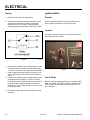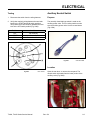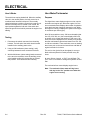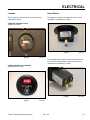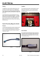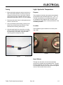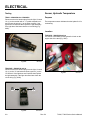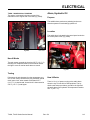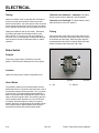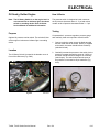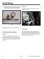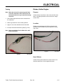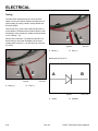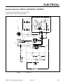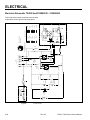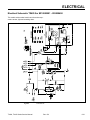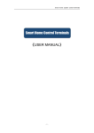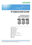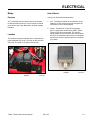
1
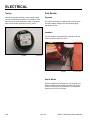
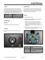
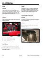
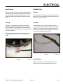
ELECTRICAL Relay How It Works Purpose A relay is an electrically actuated switch. The TX 420/425 use two relays to direct current flow to different areas of the unit. The two relays are the kill relay and the start relay. Electrically, they both operate the same. 1. Coil: Terminals 85 and 86 are connected to a coil. Applying 12 volts to these terminals energizes the coil turning it into an electromagnet. 2. Switch: Terminals 30, 87 and 87a are actually part of a single pole, double throw (SPDT) switch. Terminal 30 is the common lead. The switch is spring loaded so that 30 and 87a are connect when the coil is not energized. When the coil is energized, the switch is “thrown” and 30 and 87 are connected (Fig. 0280). Location The relays are located under the hood, mounted to the tower assembly (Fig. 0279). The relay on the left is the start relay. The relay on the right is the kill relay. Fig 0279 TX420, TX425 Series Service Manual Fig 0280 MVC-0671 IMG-6903 Rev. 001 6-1 ELECTRICAL Testing Ignition Switch 1. Disconnect the relay from the harness. Purpose 2. Verify the coil resistance between terminals 85 and 86 with a multimeter (ohms setting). Resistance should be from 70 to 90 ohms. There should be continuity between terminals 87a and 30 (Fig. 0281). This component provides the proper switching for the starter, ignition, accessories, and safety circuits. Location The ignition switch is mounted on the right hand side of the control panel (Fig. 0282). Fig 0281 xl relay 3. Connect the multimeter (ohms setting) leads to relay terminals 30 and 87. Ground terminal 86 and apply +12 VDC to terminal 85. The relay should make and break continuity between terminals 30 and 87 as 12 VDC is applied and removed from terminal 85 (Fig. 0281). 4. Connect the multimeter (ohms setting) leads to relay terminals 30 and 87a. Apply +12 VDC to terminal 85. With terminal 86 still grounded, the relay should break and make continuity between terminals 30 and 87a as 12 VDC is applied and removed from the terminal (Fig. 0281). Fig 0282 IMG-6924 How It Works Detents inside the ignition switch give it 3 positions: OFF, RUN, and START. The START position is spring loaded so the cylinder automatically returns to RUN once the key is released. 5. Disconnect voltage and multimeter leads from relay terminals. 6-2 Rev. 001 TX420, TX425 Series Service Manual ELECTRICAL Testing Auxiliary Neutral Switch 1. Disconnect the switch from the wiring harness. Purpose 2. Verify that continuity exists between the terminals listed for the START and RUN switch positions. Verify that there is NO continuity between the terminals in the OFF switch position (Fig. 0283). The normally closed ball type switch is used on the auxiliary power valve. This is a safety switch to make sure the auxiliary power valve is in the neutral detent (Fig. 0284). Position Condition OFF No continuity START B+I+S RUN B + I + A and X + Y Fig 0284 CLR MVC-866X Location Fig 0283 MVC-166 art Open the rear door, or remove the rear panel. The neutral switch is threaded into the lower portion of the auxiliary valve (Fig. 0285). TX420, TX425 Series Service Manual Rev. 001 Fig 0285 IMG-6984a 6-3 ELECTRICAL How It Works Hour Meter/Tachometer The switch has a spring loaded ball. When the auxiliary valve is in the neutral position, the ball moves into a machined notch located in the spool. The normally closed switch then provides a ground to the start circuit. When the auxiliary lever is moved out of neutral, the spool pushes against the ball end of the switch and opens the ground circuit which prevents the engine from starting. Purpose The digital hour meter displays engine run time, service reminders and engine rpm. When the engine is off, the hour meter/tachometer displays the number of operation hours that have been logged on the traction unit. When the engine is running, it displays the speed of the engine in revolutions per minute (rpm). After 50 hours and then every 100 hours thereafter (that is at 150, 250, 350, etc.) the screen displays CHG OIL to remind you to change the engine oil. After every 100 hours, the screen displays SVC to remind you to perform the other maintenance procedures based on a 100, 200, or 400 hour schedule. These reminders come on starting three hours prior to the service interval time and flash at regular intervals for six hours. Testing 1. Disconnect the switch connector from the wiring harness. The ball end of the switch should remain installed in the auxiliary power valve. 2. Using a VOM multimeter (ohms setting), verify continuity between the two connector terminals. 3. With the Multimeter (ohms setting) leads connected to the two wire terminals, move the auxiliary power valve handle to either the reverse flow or forward flow position. There should be NO continuity. The service icon (looks like an hourglass) is set-up to flash at 8 hours (Break-in Period) and then every 99 hours. At every 99 hour interval, a “SVC” icon will flash. The “SVC” icon is a reminder to change the hydraulic oil and filter. The mechanical hour meter displays engine hours. Note: The mechanical hour meter will log hours with key in the “On” position even when the engine is not running. 6-4 Rev. 001 TX420, TX425 Series Service Manual ELECTRICAL Location How It Works The hour meter is mounted in the control panel (Fig. 0286 and Fig. 0287). The digital hour meter is an electronic clock. It is not repairable or resettable (Fig. 0288). TX420/425 210000501 and up (Digital hour meter) Fig 0286 The mechanical hour meter provides the hours the key is in the ON or RUN position. It does not provide any maintenance reminders (Fig. 0289). Fig 0287 TX420, TX425 Series Service Manual IMG-7016 IMG-7013 TX420 200000100 thru 210000500 (Mechanical hour meter) Fig 0288 Fig 0289 IMG-7006a IMG-7005 Rev. 001 6-5 ELECTRICAL Testing Location The digital hour meter should be replaced if any of the functions do not work properly. Prior to replacing the hour meter, check the continuity using VOM multimeter (ohm setting) on the wire from the spark wire to the hour meter. If the wire continuity test is good, then replace the hour meter. The neutral proximity switch is located under the center panel of the control panel. The drive handle and the center panel must be removed to access the neutral switch (Fig. 0291). The mechanical hour meter should advance in hours when 12 volts is connected to the positive “+” terminal and ground is connected to the negative “-” terminal on the hour meter. If the hour meter does not advance in hours, then replace the hour meter. If the hour meter does advance in hours then check the wires connected to the hour meter. Neutral Proximity (Magnetic) Switch Purpose The neutral proximity switch ensures the traction control lever is in the neutral/stop position when starting the unit. It is a magnetic type switch and it must be in close proximity to the traction control lever bolt to close the contacts (Fig. 0290). Fig 0291 IMG-7027 How It Works The neutral proximity switch has a sense zone which is the magnetic portion on the switch. A bolt located on the traction control lever aligns with the sense zone in the neutral/stop position to magnetically close the contacts in the switch (Fig. 0292). Fig 0290 CLR MVC-878X 6-6 Rev. 001 Fig 0292 CLR MVC-885X TX420, TX425 Series Service Manual ELECTRICAL Testing Light, Hydraulic Temperature 1. Before electrically testing the switch, check the location of the switch and bolt, to make sure they are meeting in the sense zone on the switch. Both the switch and the bolt are adjustable and the air gap between them should be 1/8” to 1/4” (3.2 to 6.4mm). Purpose 2. Disconnect the switch from the wiring harness and remove it from the unit. The temperature light alerts the operator that hydraulic oil temperature has reached at least 235° F (112.7° C). The light is operated by a grounding temperature sensor threaded into the hydraulic tank. The light is also connected to an audio alarm to notify the operator of the overheating condition. 3. Using a multimeter (ohms setting), check the continuity of the switch at the wire terminals. There should be NO continuity (switch open). Location The temperature light is located on the control panel (Fig. 0294). 4. Using the steel blade of a screw driver, or similar object, touch the blade of the screw driver against the sense zone of the switch. There should be continuity (switch closed) (Fig. 0293). Fig 0293 Fig 0294 IMG-6922 CLR MVC-879X How It Works The light is on the same circuit as the temperature sensor that is threaded into the hydraulic tank. The tank sensor grounds the circuit at 235° F (112.7° C) resulting in a completed electrical circuit which causes the light to come on and an audio alarm to sound. TX420, TX425 Series Service Manual Rev. 001 6-7 ELECTRICAL Testing Sensor, Hydraulic Temperature TX420 - 200000100 thru 210000999 Disconnect the wire harness plug from the light. Connect 12v (+) to the terminal with a “+” symbol stamped into it and connect the ground (-) to the other terminal. If the light does not illuminate then replace the light assembly. If the light does illuminate check the circuit wiring (Fig. 0295). Purpose The temperature sensor indicates that the hydraulic oil is overheating. Location TX420/425 - 220000100 and up The sensor is threaded into the hydraulic oil tank on the engine side of the tank (Fig. 0297). Fig 0295 IMG-6964 TX420/425 - 220000100 and up Disconnect the wire harness plug from the light. Connect 12v (+) to the “A” terminal and connect ground (-) to the “B” terminal. If the light does not illuminate then replace the light assembly. If the light does illuminate check the circuit wiring (Fig. 0296). B 6-8 Fig 0297 IMG-6911a A Fig 0296 IMG-6962a Rev. 001 TX420, TX425 Series Service Manual ELECTRICAL Alarm, Hydraulic Oil TX420 - 200000100 thru 210000999 The sensor is mounted in the lower center of the mainframe on the engine side of the tank (Fig. 0298). Purpose The audible alarm produces a pulsating loud tone to alert the operator of overheating hydraulic oil. Location The audio alarm is located in the control panel under the left control panel cover (Fig. 0299). Fig 0298 MVC-419S How It Works The tank sensor grounds the circuit at 235° F (112.7° C) resulting in a completed electrical circuit which causes the light to come on and an audio alarm to sound. Fig 0299 IMG-6937 Testing Disconnect the wire harness from the temperature sensor. An ohm meter, hooked to the plug terminals, should read “open circuit” when tested at less than 235° F (112.7° C). It should read “closed circuit” when tested at 235° F (112.7° C) and higher. TX420, TX425 Series Service Manual How It Works There is 12v (+) of power running to the audio alarm when the key is in the ON or RUN positions. The hydraulic tank sensor provides a ground for the light and the audio alarm if the hydraulic oil temperature reaches 235° F (112.7° C) . Rev. 001 6-9 ELECTRICAL Testing Fuel Sender Ground the negative terminal (-) on the alarm. Apply 12volts to the positive terminal (+) on the alarm. If the alarm does not sound, replace the alarm. If the alarm does sound test the electrical circuit (Fig. 0300). Purpose This electrical component monitors the fuel level in the fuel tank sending voltage to the control panel gauge indicating fuel level. Location The fuel sender is mounted on the right side of the top surface of the fuel tank (Fig. 0301). Fig 0300 IMG-6969a Fig 0301 CLR DSC-0672 How It Works A float is attached to a pivoting lever. The pivoting lever rotates a potentiometer (a device similar to the volume control on a stereo) to vary resistance. The resistance should vary from 33 to 240 ohms. 6-10 Rev. 001 TX420, TX425 Series Service Manual ELECTRICAL Testing How It Works Disconnect the two wires and remove the mounting screws. Remove the sender from the fuel tank. Place the VOM negative lead on the negative terminal and the positive lead on the center stud. Refer to the chart below for proper resistance depending on float position. The meter moves in proportion to the amount of resistance provided by the fuel level sender located in the fuel tank. The movement is dampened to compensate for movement of the fuel in the tank. Float Position Resistance Full 33 ohms + 20 ohms Empty 240 ohms + 6 ohms Testing 1. Check the 10 amp fuse. 2. With the gauge still connected to the harness, turn the key to the ON position. Fuel Gauge 3. Using a VOM, set scale capable of reading 12 volts DC. Connect the negative lead to the ground terminal (G) and the other lead to the positive terminal (S) (Fig. 0303) to verify the conditions in the table below. Purpose The gauge indicates the fuel level in the tank. 4. Replace the gauge if the fuel sender tests correctly but voltage/fuel level indication does not. Location The fuel gauge is located on the control panel (Fig. 0302). G I S Fig 0303 Terminal Fig 0302 IMG-6921 IMG-6971 Reading G 0 Volts - Ground I 12 Volts (B+ from Ignition switch) S 2.5 Volts tank full* S 7.5 Volts tank empty* *All voltage readings should be within 20%. (Typical values) TX420, TX425 Series Service Manual Rev. 001 6-11 ELECTRICAL Fuses Testing Purpose A failed fuse will often be discolored or melted. Please note that not all fuse failures are easy to see. A fuse can be checked with a continuity tester if there is doubt. If there is no continuity between the fuse terminals, replace the fuse, even if it appears good. Fuses are used in the circuits to limit damage in the event of excessive current flow. If a fuse fails, look for a short circuit, a corroded/poor connection, or any component that appears to have been overheated. A failed fuse is a sign of a problem in that circuit. Hydraulic Oil Cooler Fan Location Purpose Fuses are located under the hood, mounted to the tower assembly (Fig. 0304). The hydraulic oil cooler fan creates air flow across the oil cooler to dissipate heat. Location The fan is mounted in the hood within a sheet metal housing (Fig. 0305). A BCD A. B. C. D. Fig 0304 IMG-6972 15 amp = Fan motor 10 amp = Neutral switch and gauges 25 amp = Charge and fuel solenoid 30 amp = Start circuit Fig 0305 IMG-6979a How It Works The fuse block is where the wires that carry 12 volts meet the wires that need 12 volts to operate a component or function. The fuse makes the connection between the 12 volt wire carrying the current and the 12 volt wire that needs the current. 6-12 Rev. 001 TX420, TX425 Series Service Manual ELECTRICAL How It Works Fusible Link The fan runs with the key in the ON and RUN positions. When the hood is closed, the fan draws cool air in from the side openings in the hood and pushes the cool air through the sheet metal housing over the top of the oil cooler. Purpose Testing Location Check the 15 amp fuse first. Disconnect the fan wire plug from the wire harness. Apply 12v (+) to the blue wire and negative (-) to the black wire on the fan motor. If the fan motor runs, then check the wire harness ahead of the fan connection. The fusible link is a 6” (15.2cm) long blue wire with a round eyelet connected to the B+ terminal on the starter solenoid. The blue wire is connected to the red B+ wire coming from the ignition switch. The connection is protected by heat shrink tubing (Fig. 0307). The fusible link wire is smaller than the rest of the circuit and acts as a high-current fuse that protects the circuits from excessive current draw. Replace the fan if it fails to run or runs improperly with 12v applied directly to the fan motor terminals (Fig. 0306). Fig 0306 IMG-6989 Fig 0307 PICT-4328a How It Works When current flow in the circuit exceeds that of the fusible link, the wire melts and interrupts the circuit. TX420, TX425 Series Service Manual Rev. 001 6-13 ELECTRICAL Testing TX420/425 Serial 200000100 – 250000399: The brake switch is open when the brake is in the ON position. Check for a failure of the 30 amp fuse first. Disconnect the wire from the starter solenoid. Remove the heat shrink from the splice. Use a test light to check for power at the terminal end and of the splice. If power is present at one end and not the other, then the fusible link is bad. Testing the fusible link with an ohmmeter: Disconnect the battery and attach the ohmmeter leads to each side of the link. If it is good, you will get a reading on the meter. If not, it will read open. A fusible link that has seen excessive current will also have brittle or melted insulation. TX420/425 serial 270000999: The brake switch is open when the brake is in the OFF position. Testing Connect the ohm meter leads to the brake switch terminals that are across from one another (either the top two or the bottom two terminals). When the brake switch is compressed there should be continuity. When the brake switch is released it will read open (Fig. 0308). Brake Switch Purpose A B To shut the engine down if the brake is in the ON position. This will prevent damage to the drive system. Location Under the control panel, under the right hand cover. How It Works The proximity (traction control neutral) switch and the brake switch work in conjunction with each other. One of the switches must be closed to provide 12v (+) of power to the kill relay. The brake handle pushes against the button on the switch and completes the circuit to the kill relay to allow the engine to start. The proximity (traction control neutral) switch provides 12v (+) to the kill relay for starting. Once the engine is running, moving the traction control out of neutral opens the proximity switch. If the parking brake is applied (switch open) power is removed from the kill relay and the engine stops. 6-14 A. Top Rev. 001 Fig 0308 IMG-6986a B. Bottom TX420, TX425 Series Service Manual ELECTRICAL Oil Sentry, Kohler Engine How It Works Note: The Oil Sentry Switch is on the engine but it is not connected to an indicator light, shut down switch or sounding devise. Refer to Kohler Service Manual for additional information. The pressure switch is designed to break contact as the oil pressure increases above 3 - 5 psi and makes contact as the oil pressure decreases below 3 - 5 psi. Testing Purpose Optional oil pressure monitor switch. The switch will shut off the engine or activate an indicator light or sounding device. Location The Oil Sentry Switch is located in the breather cover in front of the carburetor (Fig. 0309). Fig 0309 Compressed air, a pressure regulator, pressure gauge and continuity tester are required to test this switch. 1. Connect continuity tester across the blade terminal and the metal case of the switch. With 0 psi applied to the switch, the tester should indicate continuity (switched closed). 2. Gradually increase the pressure to the switch. As the pressure increases through the range of 3.0/5.0 psi the tester should indicate a change to no continuity (switch open). The switch should remain open as the pressure is increased to 90 psi maximum (Fig. 0310). IMG-7274 TX420, TX425 Series Service Manual Rev. 001 Fig 0310 IMG-7279a 6-15 ELECTRICAL 3. Gradually decrease the pressure through the range of 3.0/5.0 psi the tester should indicate a change to continuity (switch closed) down to 0 psi (Fig. 0311). Fig 0311 Location The solenoid is mounted on the carburetor on the flywheel side (Fig. 0312). IMG-7277a 4. Replace the switch if it does not operate as specified. Fig 0312 IMG-7272a How It Works The solenoid is attached in place of the fixed main jet screw. The solenoid has spring loaded pin that retracts when 12 volts is applied to the wire lead. The pin blocks the main fuel jet and prevents fuel entering the carburetor when solenoid is not energized. Fuel Solenoid, Kohler Engine Purpose The fuel solenoid shuts the fuel off from entering the carburetor when the ignition key is turned to the off position. Simultaneously ground is applied to the ignition coils so fuel and spark are shut off resulting in engine shut down. 6-16 Rev. 001 TX420, TX425 Series Service Manual ELECTRICAL Testing Diodes, Kohler Engine Note: When the solenoid is removed gas will leak out of the carburetor. Shut of the fuel to the carburetor and use a rag to catch fuel already in the line. Purpose 1. Shut off the engine and remove the solenoid from the carburetor. 2. Attach a ground wire to the mounting bracket. A diode allows current flow in the circuit with little resistance. It provides protection to the circuit from a large current draw. Location 3. Apply 12 volt to the solenoid male wire terminal. Diodes are located approx 8” (20.3cm) from the fuel solenoid female terminal behind the flywheel housing (Fig. 0314). 4. If the pin retracts the solenoid is good (Fig. 0313). Note: Refer to the Kohler Service Manual for additional information. Fig 0313 Fig 0314 IMG-7298a IMG-7269a How It Works A diode will only allow electrical current to flow in one direction and blocks it in the opposite direction. TX420, TX425 Series Service Manual Rev. 001 6-17 ELECTRICAL Testing The heat shrink material will have to be removed to obtain access to the diodes. Digital multimeters have a special setting for testing a diode, usually labeled with the diode symbol. Connect the red (+) lead to the anode and the black (-) to the cathode. The diode should conduct and the meter will display a value (usually the voltage across the diode in mV, 1000mV = 1V). Reverse the connections. The diode should NOT conduct this way so the meter will display “off the scale” (usually blank except for a 1 on the left) (Fig. 0315 and Fig. 0316). B Fig 0316 A. Minus (-) A IMG-7301a B. Plus (+) Diode symbol (Fig. 0317) A A. Minus (-) B Fig 0315 A IMG-7300a B. Plus (+) A. Anode 6-18 B Rev. 001 Fig 0317 diode symbol B. Cathode TX420, TX425 Series Service Manual ���� ����� �� � �� � � ����� ������� ��� ��� � �� �� �� ����������� ��������� �� ���������� ����������� ������� ���� ������ ���� �� �� ��� �� �� �� �� � ������ ���� �������� �� �� �� � � �� �� �� ����������� �� �� � �� ��������� �� ���������� ��������� � ������� ��������� � ������������������ Rev. 001 �� �� �� ��� � � �� � � �� � �� � ����������� ���������� �������� �� ���������� ���������� � � �� ��������� ��� � 1 3322-880 elec � �� �� � ���������������� � �� � � �� TX420, TX425 Series Service Manual Fig 0318 . � � � � � ����������� � � � �� �� ��� ��� ��� � � �� ��� ����� ��� ��� �� �� �� �� �� �� � � ��� ������ �� �� � ��������� � � ������ ����� ������ ��� ��� ���� ���� �������� ��������� ��� � � �������� ����� ������� �������� ������� ������������ ������ ���� ����� ���� ����� ����� �� ��� �������������� ����������������� ���������� ��������� ������������������������������� �������������� ������������ � � � ����� � ELECTRICAL Electrical Schematic TX420 Ser #200000100 - 200000999 This model serial number break has no fan but has a temperature sensor, light and sounding alarm. 6-19 . Rev. 001 ���� ����� �� �� � � ��������� ����� ������� �� �� � �� �� �� ��� ��� ������������������ �� �� �� � � �� ����������� ��������� �� ���������� ����������� ������� ���� ������ ���� �� �� ��� �� �� �� �� � � � ������ ���� �������� ���������� ������������������ �� �� � � �� �� �� �� � �� ��������� �� ���������� ��������� ����������� �� � � �� �� � � �� � �� � ����������� ���������� �������� �� ���������� ���������� � � �� ��������� ��� �� �� ��� � ������������� ���������������� �� �� � � �� � � �� � � � � . 6-20 Fig 0319 � � � � � � ����������� � � � �� �� ��� ��� ��� � � �� ��� ����� ��� ��� �� �� �� �� �� �� � � ��� ������ �� �� � ��������� � � ���� ������ ����� ������ ��� ��� ���� �������� ��������� ��� � � �� �������� ����� ������� �������� ������� ������������ ������ ���� ����� ���� ����� ����� �������������� ����������������� ���������� ��������� ������������������������������� �������������� ������������ � ����� � � ELECTRICAL Electrical Schematic TX420 Ser #210000100 - 210000500 This model serial number break has a fan kit and a temperature sensor, light and sounding alarm. 2 3325-168 elec TX420, TX425 Series Service Manual . ELECTRICAL Electrical Schematic TX420 Ser #210000501 - 220000400 This model serial number break has a fan and a temperature sensor, light and sounding alarm. Fig 0320 TX420, TX425 Series Service Manual 3 3325-662 elec Rev. 001 6-21 P5 OPTIONAL HEADLIGHTS 6-22 Fig 0321 GND BK 2 _ OR + FAN MOTOR 1 Rev. 001 BK OR FUEL GAUGE S OR BK + _ PK OR PK 10A F3 VIO T GN BK K1 KILL RELAY T GND BK BK BN W R CLOSED WHEN OUT OF DETENT SW 5 DETENT T BU GN GN SW 1 BRAKE ON PK SW 2 CLOSED NEUTRAL WHEN BRAKE CLOSED WHEN IS OFF IN NEUTRAL BN BN I G 15A F4 X I A Y S B 1 J5 3 2 5 4 K3 START RELAY 30A F1 R MAG 1 B+ START OIL REG 5 2 W HOUR METER TACH FUSIBLE LINK W BU VIO 25A F2 VIO Ignition switch terminal locations viewed from back Y OR ORANGE _ OIL SWITCH + AC AC SPARK PLUG FUEL SOLENOID SPARK PLUG SOLENOID SHIFT STARTER IGNITION MODULES U1 KOHLER TACK ENG YELLOW WHITE W GY GREY TAN RED VIO VIOLET T BU BLUE GN GREEN R BN BROWN WIRE COLOR CODES BK BLACK PK PINK START = B I S KEY SW ON = B I A and X Y B OFF = no connections A I S Y X ELECTRICAL Electrical Schematic TX420 Ser #220000401 - 270000999 This model serial number break has a fan but no temperature sensor, light or sounding alarm. 3327-244 elec 4 3327-244 elec a TX420, TX425 Series Service Manual P5 OPTIONAL HEADLIGHTS Fig 0322 TX420, TX425 Series Service Manual GND BK 2 _ OR + FAN MOTOR 1 Rev. 001 BK OR FUEL GAUGE S OR BK + _ PK I PK BK T GND BK BK BN CLOSED WHEN IN NEUTRAL SW 2 NEUTRAL OR K1 KILL RELAY G 15A F4 W BN PK R SW 5 DETENT T BU GN GN BN GN CLOSED WHEN OUT OF DETENT 10A F3 VIO X I A Y S B 1 J5 3 2 5 4 K3 START RELAY 30A F1 R MAG 1 B+ START OIL REG 5 2 W HOUR METER TACH FUSIBLE LINK W BU VIO 25A F2 VIO Ignition switch terminal locations viewed from back _ OIL SWITCH + AC AC SPARK PLUG FUEL SOLENOID SPARK PLUG YELLOW SOLENOID SHIFT STARTER IGNITION MODULES KOHLER TWIN Y OR ORANGE WHITE W GY GREY TAN RED VIO VIOLET T BU BLUE GN GREEN R BN BROWN WIRE COLOR CODES BK BLACK PK PINK START = B I S KEY SW ON = B I A and X Y B OFF = no connections A I S Y X ELECTRICAL Electrical Schematic TX420 Ser #280000100 - 280000999 This model serial number break has no brake switch, hydraulic temperature switch, light or sounding alarm. 3359-197 elec 5 3359-197 elec a 6-23 OIL TEMP ALARM OPTIONAL HEADLIGHTS P9 (–) (+) OR PK 6 3329-749 elec Rev. 001 OR BK CLOSES WHEN TEMPERATURE EXCEEDS 235F BK FUEL SENDER 3 S FUEL GAGE HYDRALIC OIL OR TEMP. LAMP TEMP SENSOR (NO) OR PK GND BK OR 1 PK BK K1 OR BK (KILL RELAY) – 2 1 15A F4 PK BN BK T W BK A 3 OR T Y 2 T GND BN GN GN S 5 BN T CLOSED WHEN OUT OF DETENT SW5 (DETENT) 3 CLOSED WHEN BRAKE IS OFF 4 SW1 PK (BRAKE ON) 10A F3 VIO I J5 SW2 (NEUTRAL) CLOSED WHEN IN NEUTRAL 5 2 2 4 3 1 + X 1 2 FAN MOTOR – + BU K3 (START RELAY) GN R B 4 1 6-24 Fig 0323 5 4 3 SW4 (IGNITION SWITCH) R R R X S I F1 30A F2 25A W BU W 1 5 2 HOUR METER TACH FUSIBLE LINK VIO VIO VIO B+ MAG START OIL REG W OR GY GN + OIL SWITCH CLOSES WITH PRESSURE AC AC SPARK PLUG – U1 YELLOW WHITE VIOLET TAN RED PINK FUEL SOLINIOD SPARK PLUG Y W VIO T R PK SOLINOID SHIFT STARTER IGNITION MODULES KOHLER TACK ENG ORANGE GREY GREEN BLUE BN BU BLACK BROWN BK WIRE COLOR CODES OFF = no connections ON = BIA and XY START = BIS Ignition switch terminal locations viewed from back A B KEY SW Y ELECTRICAL Electrical Schematic TX425 Ser #220000100 - 270000999 l . TX420, TX425 Series Service Manual ELECTRICAL Electrical Schematic TX425 Ser #280000100 - 280000999 This model serial number break has no brake switch. Fig 0324 TX420, TX425 Series Service Manual 7 3359-197 elec Rev. 001 6-25 ELECTRICAL THIS PAGE INTENTIONALLY LEFT BLANK. 6-26 Rev. 001 TX420, TX425 Series Service Manual