1
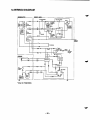
SERVICE
MAIUUAL
- --
Model
RGD2500,RGD3300
Generator
PUB-GS1186
Rev. 8198
CONTENTS
Section
Page
1 SPEClFlCATlONS....................................................................................................... 1
Tile
.
.
2 PERFOMANCE CURVES...........................................................................................
2
2-1 MODEL RGD2500 .................................................................................................
2-2 MODEL RGD3300 .................................................................................................
2-3 DC OUTPUT .........................................................................................................
2
2
2
..................................................................................................................
3
.
3 FEATURES
..........................................................................................
.
4 GENERAL DESCRIPTION
4-1 EXTERNAL VIEW .................................................................................................
4-2 CONTROL PANEL ................................................................................................
4
4
5
4-3 LOCATION of SERIAL NUMBER and SPECIFICATION NUMBER......................
6
...........................................................................
7
.
5 CONSTRUCTION AND FUNCTION
5-1 CONSTRUCTION ................................................................................................. 7
5-2 FUNCTION ............................................................................................................
7
5-3GENERATOR OPERATION................................................................................ 11
.
.........................................................................................
7. RANGE OF APPLICATIONS ....................................................................................
8. MEASURING PROCEDURES..................................................................................
6 SAFETY PRECAUTIONS
8-2 AC OUTPUT MEASURING .................................................................................
15
18
18
21
8-3DC OUTPUT MEASURING.................................................................................
21
8-4 MEASURING INSULATION RESISTANCE ........................................................
22
24
24
24
24
25
26
26
27
29
29
8-1 MEASURING INSTRUMENTS ...........................................................................
.
.
14
....................................................................
9 CHECKING FUNCTIONAL MEMBERS
9-1 VOLTMETER .......................................................................................................
9-2 AC RECEPTACLES ............................................................................................
9-3 NO-FUSEBREAKER ...........................................................................................
9-4 STATOR ..............................................................................................................
9-5 ROTOR ASSEMBLY...........................................................................................
9-6 CONDENSER .....................................................................................................
9-7 DIODE RECTIFIER .............................................................................................
10.DISASSEMBLY AND ASSEMBLY
10-1 PREPARATION and PRECAUTIONS ...............................................................
..........................................................................
Section
Title
Page
10-2 SPECIAL TOOLSfor DISASSEMBLY and ASSEMBLY ....................................
29
10-3DISASSEMBLY PROCEDURES .......................................................................
30
10-4 ASSEMBLY PROCEDURES ............................................................................. 38
10-5 CHECKING. DISASSEMBLY and REASSEMBLY of the CONTROL BOX ....... 51
t 1 TROUBLESHOOTING
53
11-1 NO AC OUTPUT ................................................................................................
53
11-2 AC VOLTAGEI
S TOO THIGH OR TOO LOW...................................................
54
11-3AC VOLTAGE IS NORMAL AT NO.LOAD. BUTTHE LOAD CANNOT BE APPLIED .....55
11-4 NO DC OUTPUT...............................................................................................
56
11-5 OIL SENSOR TROUBLE SHOOTING .......................
.......................................
57
12 WIRING DIAGRAM.................................................................................................
58
.
.
............................................................................................
r
Model
RGD3300
RGD2500
Brushless, Self Exciting, 2-Pole, Single Phase
I Frequency
I
60 Hz
60 Hz
Maximum Output
2500 W
3300 W
Rated Output
2200 W
3000 W
I
I
I
U
0
AC
sz
a
W
5
a
120 v
Rated
Current
Voltage
120 v
18.3 A
120V/240V
25.0N 12.5A 120Vl240V 18.3N
9.2A
1.o
Power Factor
12 V-8.3 A (100 W)
DC Output
Condenser Type
Voltage Regulator
Air-Cooled CCycle, Diesel Engine
Type
Model
I
DY23-2D
I
Displacement
Rated Output
i
I
230 cm3
(14.04
cu.
in.)
4.8 HP / 3600 rpm
Fuel Tank Capacity
~~~
~
Rated Coutinuous Operation
I
5.5 HP / 3600 rpm
light
oil
Fuel
I
1.10 hours
hours
1.30
0.9 liters
Recoil Starter and Optional Electric Starter
- Starting System
I
!
I
2.06 U.S. gal. (7.8 liters)
Oil Capacity
I Dimensions (Lx W x H)
I Dry Weight
265 cm3
(16.17
cu.
in.)
I
Diesel
~~
DY27-2D
i
~
~
25.0 A
21.1 ~ 1 5 . 8 ~ 1 8 . 0 i n ( 2 7 . 9 ~ 1 5 . 8 ~ 1 8 . 0 i n ) ’ / 5 3 6 ~ 4 0 0 ~ 4 5 8
mm (709 x 400 x.458 mm)*
I
I
55 kg(58.5kg.)’
/ 121 Ibs.
(129 Ibs.)’
Electric starter motoris available asoption.
-
1-
58.5 kg (62 kg.)’ / 128.7 Ibs.
(137 I&.)*
2. PERFOMANCE CURVES
2-1 MODEL RGD2500
Output Max. ................. 2500 W
Output Rated ............... 2300 W
Frequency ....................
60 Hz
Voltage .........................
120 V
- 2k
ts
A
- lk
a
n
I3
O
- 0
CURRENT(A)
-
2-2MODEL RGD3300
3k
2k
t
Output Max. .............. 3300 W
Output Rated ............3000 W
Frequency .................60 Hz
120 V/240V
Voltage ......................
e
CI
3
Y
0
CURRENT (A)
+
2-3DC OUTPUT
DC Voltage ..................12 V
DC Ampere .................8.3A
v
5
DC output .................... 100 W
16
14
The voltage curve shown in the left indicates the characteristic of DC output when charginga battery. The
voltage may be decreased by 20% when the resistance load is applied.
12
g 10
NOTE :It is possibleto use bothDC and AC outputs
simultaneously upto the rated outputin total.
0
2
4
6
CURRENT(A)
8
1
"
+
0
- 2-
3-1 BRUSHLESSALTERNATOR
Newly developed brushless alternator eliminates troublesome brush maintenance.
3-2 EASYSTARTING
Light pull recoil starter accompanied with automatic decompression system makes the new RGD series
generators even easier in starting than gasoline engine generators.
3-3 QUIET OPERATION
The new KGD series generator provides quiet operation by means of:
The superb design of intake-exhausr system.
Direct injection combustion system.
A large super silent muffler.
An efficient low noise air cleaner.
3-4 ECONOMICALPERFORMANCE
On top of well known diesel economy. the air-coolea Robin diesel engine features direct fuel injection
and special design refinemem for extra fuel efficiency.
3-5 OIL SENSOR
The OIL SENSOR automatically shuts the engine off whenever the level
oil falls down below a safelevel
preventing engine seizure.
3-6 COMPACT, LIGHT WEIGHT
The combination of newiy developed brushless alternator and air-cooled single cylinder Robin diesel
engine enables the newRGD series generators t o be very compact in size and lightin weight.
3-7 RELIABLEPERFORMANCEWITH MINIMAL MAINTENANCE
A brushless alternator eliminates troublesome brush maintenance.
A drip-proof alternator design.
A trouble free condenser voltage regulator.
A fuseless circuit breaker.
A dust-proof dual element air cleaner.
The OIL SESSOR automatically shuts the engine off whenever the oil level falls down below a safe
level preventing engine seizure.
3-8 LONG-LIFEDURABILITY
C'onlpact and smooth running air-cooledRobindieselenginelastsmuchlongerthanthegasoline
engine of the same size.
Trouble-freebrushlessalternatorwithcondensertypevoltageregulatorworksalltheyearround
without any maintenace work.
-
3-
4.GENERAL DESCRIPTION
4-1 EXTERNAL VIEW
Speed control
lever
Rocker
cover
No-fuse
Full mwer switch
( D U voltage
~
type o
Ibmakei
/
/
Air cleaner
/
Key switch
(Only for RGD3300)
\
Fuel injection pump
\ Stop lever
DC output terminal
/
Earth terminal Oil
fi&r Fuel
filter
Muffler
/
Electric starter
(only for RGDSOO)
\
Oil gauge
-
4-
.
cock Fuel
4-2 CONTROL PANEL
RGD2500, RGD3300 :60HZ-l20V, 60H~-120V/240VTYPE
Full power switch
/ No-fuse breaker
Key switch
(Only for RGD3300)
i,
Vottmeter
@
DC output terminal
_-
I((
11
/Ac
7
receptacle
/ Earth terminal
DC fuse
- 5-
4-3 LOCATION of SERIAL NUMBER and SPECIFICATION NUMBER
Serial number and specification number are stamped
on the LABEL (MODEL NAME) stuck on the side
wal of control box.
NOTE :Always specify these numbers when inquiring about the generator or ordering
spare parfs in
order to get correct parts and accurate service.
Specifications label
-
6-
w
5.CONSTRUCTION AND FUNCTION
Generator
Mount
base
rubber
Ball
bearing
Through
bolt
Support ring
Fig- 5-7
5-2 FUNCTION
5-2-1 STATOR
The stator consistsof a laminated silicon steel
sheet core, a main coil and a condenser coil which
are woundin the coreslots.
The condenser coil excites the rotor
coilfield
which
generates AC voltage in the maincoil.
Fig. 5-2
- 7-
Front
cover
5-2-2 CONDENSER
One or two condensers areinstalled in the control box and are connectedto the condenser coil
of the stator.
These condensers and condenser coil regulate
the output voltage.
I
Fig. 5 3
5-24 ROTOR
The rotor consists
of a laminated silicon steel sheet
core anda field coil whichis wound over the core.
DC current in the field coil magnetizesthe steel
sheet core. Two permanent magnetsare provided
for the primary exciting action.
Fig. 5-4
A diode rectifier and surge absorberis mounted
inside of the insulator.
Diode rectifier andSurge absorber
Fig. 5-5
- a-
5-2-4 DC FUSE
(1) The 10 ampere DC fuse mountedon the control panel protects whole DC circuit from getting damage by overload or short circuit.
(2) The 15 ampere DC fusein the control box protects the diode rectifier from getting damage
by reverse connectionto thebattery.
(Electric start model)
I
Fig. 5-6
5-2-5 NO-FUSE BREAKER
The no-fuse breaker protects the generator from getting damage by overloading or shortincircuit
the
appliance.Table 5-1 shows the capacrty of no-fuse breaker by each spec.
and their object of protection.
MODEL
RGD2500
RGD3300
SPECIFICATION
60 HZ-120V
NO-FUSE BREAKER
20 A
OBJECT or PROTECTION
60 HZ-120 V, 240V
10Ax2
Total output amperage
60 HZ-120 V
27 A
Total output amperage
14Ax2
Total output amperage
60 HZ-1 20 V, 240V
Total output amperage
Table. 5-1
1
Fig. 5-7
- 9-
5-2-6 RECEPTACLE and AC PLUG (STD.SPEC.)
These are used for taking AC output power from the generator.
A total of six kindsof receptacles, each
varying in rated voltage and current from another, are used. Each model has at least one receptacle to
deliver the rated generator output.
As many AC plugsas the receptacles, each matching the correspond5-2 shows the rated current for each receptacle. Be careful not to use
ing receptacle, are provided. Table
the receptacles and AC plugs beyond the specified amperage limits
to prevent burning.
w
NOTE 7 :If your generator has receptacles peculiar to your county, Table 5-2 does not
apply.
NOTE 2 :The generator for U.S.A. market is
equipped withNEMA standard receptacles shownin table 5-2.
Use the proper plug for connecting appliance to the generator.
Caution : To connect the appliance to locking
receptacle, insertthe plug intothe receptacle andturn it clockwise tolock.
Fig. 5-8
Style
~1
@
Ampere
125V
20A
Receptacle
AC plug
5-20R
NEMA
5-20P
125VI 250V NEMA NEMA
20A
125V
30A
NEMA
L5-30
Table. 5-2
-
10-
Description
GFCl
NEMA
(Ground Fault
Circuit interrupter)
Receptacle, duplex
Locking Receptacle
L14-2OP L14-20R
NEMA
L5-30P
Locking Receptacle
5-3GENERATOR OPERATION
PERMANENT MAGNET
STATOR
FOR INITIAL EXCITATION r--1
I
FIELD COIL
MAIN COIL
\
"
"
"
1
I
""I
Fig. 5-9
5-3-1GENERATION Of NO-LOAD VOLTAGE
(1) When the generator starts running,
the permanent magnet built-in
to the rotor generates
3 to 6V of AC
voltage inthe main coil and condenser coil wound on the stator.
(2) As one or two condensers are connected to the condensercoil, the small voltage at the condenser
8)
which flows through the condenser coil.
At this time,a small fluxis
coil generates a minute current
produced with which the magnetic force at the rotor's magnetic pole is intensified.When this magnetic force is intensified, the respective voltages in the main coil and condenser coil As
risethe
up.
current 3 increases, the magnetic flux at the rotor's magnetic pole increases further. Thus the voltby repeating this process.
ages at the main coil and condenser coil keep rising
(3) As AC current flows through the condenser coil, the density of magnetic
in theflux
rotor changes. This
in the field coil
change of magnetic flux inducesAC voltage in the field coil, and the diode rectifier
AC voltage into DC. Thus a DC current
13flows through the field coil and magnecircuit rectifies this
tizes the rotor core to generate an output voltage in the main coil.
(4) When generator speed reaches3000 to 3300 rpm, the currentin the condenser coil and field coil
of each coils. If generator speed further
increases rapidly. This acts to stabilize the output voltage
will reach to the rated value.
increases to the rated value, the generator output voltage
5-3-2 VOLTAGE FLUCTUATIONS UNDER LOAD
When theoutput current @ flows through the main coil to the appliance, a magnetic
is produced
flux
and
@ in the condenser coil. When current
@ increases, the densityof magnetic
serves to increase current
flux acrossthe rotor core rises.As a result, the current flowing in the field coil increases and the generator output voltage is prevented from decreasing.
-
11 -
5-3-3 FULL POWER SWITCH (Dual Voltage Type)
The full power switchis provided for the dual voltage type to take out the full rated power from one
receptacle in each voltage.
1"
REc21&
-1
1OV)
$""
/
Fig. 5-11
I
-
,
1
IREC1
I
110 v
,orv
1
I
I
LOWER VOLTAGE HIGHER VOLTAGE
RECEPTACLE
RECEPTACLE
Rated output
I
No output can be
taken.
I
110/220 v
or
Half of rated output
120/240 V
Tale. 5-4
Fig. 5-12
-
12-
Rated output
Two main coils are wound over stator core. Each main coil outputs
half the rated power at the lower
voltage (11OV or 12OV). These main coils are wound to in
bethe same phase. Thefull power switch
reconnects these main coils
in parallel orin series.
Fig. 5-10 shows a circuit diagram. Whenthe fullpower switchis set for single lower voltage indication
(11OV or 12OV), the switch positionis as indicated by the lower solid line in the diagram.
Fig. 5-11 is a
simplified representation of this circuit, showing two
themain coils connected
in parallel.ln this case, the
2 for the lower voltage can output up
higher voltage(22OV or 240v) at Rec. 3 cannot be taken out. Rec.
to the rated power (up30A
to if the rated currentis over 30A), and Rec.1 can output up toa total of 15A.
When the fullpower switch is set for double voltage indication
(11OV/22OV or 120V/240V), the switch
position is as indicated by the upper dotted line 5-10.
in Fig.
Fig. 5-12 is a simplified representation
of this
circuit, showing thetwo main coils connectedin series. In thiscase, powercan be taken simultaneously
3 for the higher voltage can outputtoup
the rated power,
from the receptacles for the both voltages. Rec.
but Rec. 1 and Rec.2 for the lower voltage can output only up to half the rated power each.
Table 5-4 is a summary of the above explanation. Select the proper output voltage by full powerinswitch
accordance withthe appliance to beused.
"
- 13-
6.:SAFETY PRECAUTIONS
1. Use extreme caution near fuel. A constantdanger of explosion or fire
exists.
Do not fill the fuel tank while
the engine is running. Do not smoke or use opem flame near
the fuel
If spilt, wipeit and let dry before starting the engine.
tank. Be careful not to spill fuel when refueling.
2. Do not place inflammable materials near the generator.
Be careful not
to put fuel, matches, gunpowder, oily cloth, straw, and any other inflammables near the
generator.
3. Do not operate the generator in a room,cave or tunnel. Always operatein a well-ventilated area.
Otherwise the engine may overheat and also, the poisonous carbon monoxide contained in the exm (4 feet) away from structures
haust gases will endanger human lives. Keep the generator at1least
or facilities during
use.
4.Operate the generator on a level surface.
If the generatoris tilted or moved during use, there
is a dangerof fuel spillage and a chance that the
generator may tip over.
5. Do not operate with wet hands or in the rain.
If the generatoris wet by rain or snow, wipe
it and thoroughlydry it
Severe electric shock may occur.
before starting.Don't pour water overthe generator directly nor wash
it with water. If the generator
is
will be adversely affected and may cause current leakage and electric
wet with water, the insulations
shock.
6. Do not connect the generator to
commercial
the
w
power lines.
This may cause a short-circuit or damage
to the generator. Use a transfer switch (Optional parts) for
connecting with indoor wiring.
NOTE :The parts numbersof the transfer swifches and
of the plastic box to store them
are as shown in
Table 6-1.
Part No.
Name
Part
Q'ty
Phase
Allowable Current
365-45604-08
Transfer 1Switch
1
15 A
367-45605-08
Transfer 1Switch
1
30 A
340-45606-08
Transfer Switch
1
367-43008-08
Plastic1Box
1
30 A
348-43009-08
Plastic
60
Box1
1
A
1
60 A
Table. 6-1
7. Be sureto check andremedy thecause of circuit breaker tripping before resetting it on.
CAUTION : If the circuitbreaker tripped off as a resultof using anelectrical appliance,the cause
In such a case, stop operationimmediately and carefully
can be an overload or a short-circuit.
check theelectrical appliance and AC plugs for faulty wiring.
- 14-
Generally, the power rating of an electrical appliance indicates the amount of work that can be it.done by
The electric power required for operating an electrical appliance
is not always equal to the output wattage of the appliance. The electrical appliances generally have a label showing their rated voltage, frequency, and power consumption (input wattage). The power consumption
of an electrical appliance is
the power necessary for using it. When using a generator
for operating an electrical appliance,the power
factor and starting wattage must be taken into consideration.
total wattage of all appliancesto
In order to determine the right size generator,
it is necessary to add the
be connectedto the unit.
Refer to the followings to calculate the power consumption of each appliance or equipment by its typ
(1) Incandescent lamp, heater, etc. with
a power factor of1.O
Total power consumption must be equal to or less than the rated output of the generator.
Example :A rated 3000W generator can turn thirty
lOOW incandescent lamps on.
(2) Fluorescent lamps, motor driven tools, light electrical appliances, etc. with
a smaller power
factor
Select a generator with a rated output equivalent
1.2toto 2 times of the power consumption of the
1.2 are
to 3
load. Generally the starting wattage of motor driven tools and light electrical appliances
times lager than their running wattage.
Example : A rated 250 W electric drill requires400
a W generator to starti
t
.
NOTE 7 :If a power factor correction capacitor is not applied to the fluorescent lamp, the more powe
shall be required to drive the lamps.
of the lamp.
NOTE2 :Nominal wattage of the fluorscent lamp generally indicates the output wattage
efiTherefore, if the fluorescent lamp has no special indication as to the power consumption,
ciency should be taken into account as explained
in item (5) on the following page.
(3) Mercury lamps witha smaller power factor
Loads for mercury lamps require
2 to 3 times the indicated wattage during start-up.
Example :A 400 W mercury lamp requires
800 W to1200 W power source to be turned Aon.
rated
3000 W generator can powertwo or three400 W mercury lamps.
(4) Initially loaded motor driven appliances suchas water pumps,compressors,etc.
These appliances require large starting wattage which
is 3 to5 times of running wattage.
Example :A rated 900 W compressor requires a
4500 W generator to drive it.
NOTE 7 :Motor-driven appliances require the aforementioned generator output
at the
only
shdng. Once
7.2 to 2 times their rated power contheir motors are started, the appliances consume about
used forother electrical
sumption so that the excess power generated by the generatorbecan
appliances.
(4) vary in their required motorsbrting
NOTE2 :Motor-driven appliances mentioned in Items(3) and
power depending on the kind of motor and start-up
if itload.
is dficult to determine theoptimum
generator capacw, select a generator with a larger capaciw.
- 15-
(5) Appliances withoutany indication as to power consumption
Some appliances have no indication as
to power consumption; but instead the work load (output)
is
indicated. In such a case, power consumption
is to be worked out accordingto the numerical formula
mentioned below.
(Output of electrical appliance)
(Efficiency)
= (Power consumpition)
Efficiencies of some electrical appliances are as follows
:
Single-phase motor................................
Fluorescent
lamp
...................................
The smaller the motor, the
0-753(
lower
the
efficiency.
Oe6
0.7 to
to 0.8
Example 1: A 40W fluorescent lamp means that its luminous output
is 40W. Its efficiencyis 0.7 and
accordingly, power consumptionwill be40 t 0.7=57W. As explained in Item (2), multiply
this power consumption value of
57 W by 1.2 to 2 and youwill get the figure of the necessary capacity of a generator.In other words, a generator with a rated ooutput
f 1OOOWcapacity
can light nine to fourteen
40 W fluorescent lamps.
Example 2 : Generally speaking, a400 W motor means that its work load
is 400 W. Efficiency of this
400+0.7= 570 W. When this motoris used for
motor is0.7 and power consumption will be
a motor-driven tool, the capacity of the generator should
be multiple of 570W by 1.2to 3 as
(3).570 (W) x 1.2 to 3 = 684 (W) to 1710(W)
explained in the Item
MODEL RGD3300 RGD2500
Frequency
lncandesent lamp,
heater, etc.
I
60 Hz
I
22OOw
Fluorescent lamp, Motordriven tool, general-porpose
~~~~~
Mercury lamp, etc.
Pump, compressor, etc.
I
I
approx.
13OOW
1
approx.
650 W
Table. 7-1
-
16-
30OOW
approx.
approx.
15OOW
1
60 Hz
2100 w
I
approx.
18WW
approx.
I
NOTES : Wring between generator and electrical appliances
"
I. Allowable current of
cable.
Use a cable with an allowable current that is higher than the rated input current of the load (el
of the cable used, the cable will
appliance). If the input current is higher than the allowable current
become excessively heated and deteriorate the insulation, possibly burning it out. 7-2
Table
shows
cables and their allowable currents for your reference.
2. Cable length
occurs due to the increased resistance in the conductors deIf a long cable is used, a voltage drop
damaged.Tabe
creasing the input voltage to the load (electrical product). As a result, can
thebeload
7-2 shows voltage drops per
I00 meters of cable.
Sectional A"owab'e
area / mm3 current / A
"
Gauge No'
wire dement
mm
Voltage drop per 100 m
Resistance
Ohm/100m
1~
3~
0.75
7
I 3010.18 I
2.477
1.25
12
50 10.18
1.486
1.5V
5V
7.5V
2.0
17
0.952
1.0 V
3V
5.0 V
3.5
23
10.26
37
I 45/0.32 I
I 2.5 V I 8 V
5~
0.517
I
112.5 V
I 1.5V I 2.5 V
5.5
4V
I
5 V 16.5V
2.5v I 35-v I
4v
7.5 v
5v
I
I
Table. 7-2
Voltage drop indicates as V=
1 x RxIxL
100
R
meansresistance ( hz / 100 m)on the above table.
I
meanselectriccurrentthroughthewire
L
meansthelength of thewire
(A).
(m).
The length of wire indicaters round length, it means twice the length from generator to electrical tools.
- 17-
r
8-1 MEASURING INSTRUMENTS
8-1-1 “Dr. ROBIN” GENERATOR TESTER
The “Dr. Robin” generator tester is exclusively
designed for fast, easy diagnosis and repair of
Robin generators. The “Dr. Robin” has the following features:
(1) Functions of voltmeter, frequency meter,
meggertester, capacitance meter and circuit
tester are combined in one unit.
(2) Fast and easy readout by digital indicator.
(3) Built-in automatic battery checker indicates the
time to change batteries.
Fig. 8-1
(4) Tester and accessories are installed in a handy,
sturdy case for easy carring.
SPECIFICATIONS
MODEL
I
Dr.Robin
Part Number
388-47565-08
0 to 500 V AC
Voltage
25 to 70 Hz
Frequency
Measuring
Resistance
Range
Condenser Capacity
0.1 to 1.999 Q
10 to 100 p F
insulation Resistance
3M Q
Fuse
Circuit Protector
2 x 6F44P (006P)Dry Cell Battery Power Source
I
Accessories
Test Leads with needle probes . . . 1 set
Test leads with jack plugs . . . 1 set
Dimensions (L x W x H)
I
285 mrn x 200 mm x 110 mrn
1.6 kg
Weight
Table. 8-1
The “Dr. Robinngenerator tester can be ordered from Robin generator distributors
by the following part
number.
Dr. Robin Part Number :388-47565-08
If youdo not have a “Dr. Robinngenerator tester,use the instruments described
in the following section for
checking generator parts.
- 18-
8-14 INSTRUMENTS
(1) VOLTMETER
AC voltmeter is necessary. The approximate
AC voltage ranges of the voltmeters used
to be
for various types
of generators are as follows:
0 to 150V:Type with an output voltage
of 110
or 120V
0 to 3OOV :Type withan output voltage of 220,
230 or 240V
0 to 150V, 0 to 330V : Dual voltage type
FOR AC
Fig. 8-2
(2) AMMETER
AC ammeter is necessary. An AC ammeter
with a range that can be changed according
to the current ratingof a given generator is
most desirable. (About1OA, 20A, 1OOA)
FOR AC
Fig. 8-3
(3) FREQUENCY METER
I
Frequency range:About 45 to 65Hz
NOTE :Be carefulof the frequency meter's input
voltage range.
Fig. 8 4
- 19-
(4) CIRCUIT TESTER
Used for measuring resistance, etc.
Fig. 8-5
(5) MEGGER TESTER
Used for measuring generator insulation resistance. Select one with testing voltage range
of 500V.
I
Fig. 8-6
(6)TACHOMETER
Use the contactless type tacho meter.
Fig. 8-7
- 20-
8-2 AC OUTPUT MEASURING
TO AC
Fig. 8-8
Use a circuit like the shown
in Fig.8-8 for measuringAC output. A hot plate or lamp with a power factor of
1.O may be usedas a load. Adjust the load and
rpm. and check that the voltage range is as specified in
Table 8-2 at the rated amperage and rated rpm.
Rated voltage
120
v
117 -130 V
Voltage range
240
v
-
235 260 V
Table. 8-2
8-3 DC OUTPUT MEASURING
d
To DC Terminal
Q
??
i.
"I
fig. 8-9
Measurement ofDC output is executed with the switch turned
ON while the current is regulated8.3A
at
by adjusting the load to the generator.
If the voltageis within the range from
6V to 14V, the voltageoutput
is normal.
NOTE :If a battery is connected as a load to the generator, theDC output voltage will increase by
approximately 1 to 2 K Therefore, carefully observe the electrolyte level and do not overcharge
the battery.
- 21 -
WMEASURING INSULATION RESISTANCE
Use a "Dr. Robinngenerator tester
in megger tester
mode or use a megger tester to check the insulation resistance. Connect a megger tester to one
of receptacle output terminals and the ground terminal, then measure the insulation resistance. An
insulation resistance of1 megohm or more is normal. (The original insulation resistance at the time
of shipment from the factory is 10 megohm or
more.) If it is less than Imegohm, disassemble
the generator and measure the insulation resistance of the stator, rotor and control panel individually.
Fig. 8-10
STATOR
(1) Measure the insulation resistance between
BLUE lead and the core.
(2)Measure the insulation resistance between
WHITE lead and the core.
(3) Measure the insulation resistance between
YELLOW lead and the core.
(4) Measure the insulation resistance between
BROWN lead and the core.
1
Fig. 8-11
ROTOR
Measure the insulation across one
aIf the solderec
terminals of the rotor andthe core.
-
22-
CONTROL PANEL
.-
I
Measure the insulation resistances between the
live parts and the grounded parts.
Fig. 8-13
Any part wherethe insulation resistance is less than 1M Q has faulty insulation, and may cause electric
leakage and electric shock.
Replace the faulty part.
- 23-
e
9.CHECKING FUNCTIONAL MEMBERS
w
9-1 VOLTMETER
Check the the voltmeterit is
if tumed on by applying specific voltage.
Voltmeter cannot be checked with circuit tester
because its resistance is too large.
9-2 AC RECEPTACLES
Using a "Dr. Robinnor a circuit tester, check continuity between the two terminals at the rear of the
AC receptacles while the receptacle is mounted
on
VOLTMETER
Fig. 9-1
When continuity is found between the output terminals
of the receptacle with a wire connected across
these terminals, theAC receptacle is normal. When the wireis removed and no continuity is found
between these terminals, the receptacles are also normal.
..
..
Fig. 9-24
Fig. 9-28
9-3 NolFUSE BREAKER
Check continuity between each two
of terminals
at the rear of the no-fuse breaker while it is
mounted on the control panel. Normally, thereis
two when the nocontinuity between each of the
fuse breaker is on while there is no continutty when
the no-fuse breaker is off.
Fig. 9-3
-
24-
9-4STATOR
Stator
Disengage connectors on the wires from stator
a
and check the resistance between wires with
"Dr. Robin" or a circuit tester refering to the following table.
Fig. 9-4
Hz
RGD2500
I
RGD3300
AC Winding
Specification
MODEL
60
Condenser Winding
Voltage
Brown / White
120 v
0.66
120V/240V
0.66
0.66
0.12
120 v
0.44
0.44
1
120v/240v
0.44
0.44
0.1 1
Blue / Sky-blue
Yellow / Yellow
2 0.66
Black / Orange
1.9 0.1
I
1.9
1.6 0.1
60
1.6
Thle. 9-1
NOTE :If the circuit tester is not sufficiently accurate, it may not show the values given and may give
also occur when there isa wide variationof resiserroneous readings. Erroneous readings will
tance among coil windings or when measurement is performed
at ambient temperatures different from20 OC (68 OF).
-
25-
9-5 ROTOR ASSEMBLY
(1) Using a "Dr. Robin" ora circuit tester, measure the resistance of the field coil at the terminals.
(0)
I
RGD3300
RGD2500
MODEL
RESlSTANCE
3.7 n
3.3 Q
Table. 9-2
I
NOTE 1 :
Because a diodeis soldered to thecoil ends at
the terminals, resistance may be measured only
when tester probes touche the
teminais in one
combination ofpolariw Therefore,if no resistance
reading appears,try checking in reverse poladty
NOTE 2 :
If the circuit testeris not sufficiently accurate, it
may not show
the values given and may give erroneous readings. Erroneous reading will also
occur when there
is a wide variation of resistance
among coil windings or when measurementis
performed at embient temperatures different from
20 "C(68 O F ) .
Fig. 9-5
1
9-6 CONDENSER
Use a "Dr.Robin" in capacitance meter mode to
check the capacity of condensers.
NOTE :Be sureto discharge condensers by shorting condenser leads each otber before checking
their capacitance,or the accurate reading cannot
be obtained.
I
I
NORMAL
CAPACITY
OF
CONDENSER
10pFx2
I
10pFx2
I
1
1
Fig. 9-6
* If such an instrument
is unavailable, the condenser can
be checked by replacing with a new
one. If the
generator performs good withnewcondenser,thecauseoftrouble
- 26-
is defect in original condenser.
w
9-7 DIODE RECTIFIER
Circuit insideof the diode rectifiersis as shown inFig. 9-7. Check continutty between each terminal by
as shown in Fig. 9-8. The rectifier is normal when condtinuity
is as follows:
using a circuit tester
Diode rectifier
Yellow
Yellow
Fig. 9-7
Circuit tester
Fig. 9-8
Checkina table for analoaue circuit tester.
~~
~
~~~
~~~~
~
~
~
~~
~
~
Apply black(minus) needle of the circuit tester
Analogue circuit tester
Yellow
Yellow
Apply red (plus) needle of
the circuit tester
Yellow
-
Yellow
No continuity
Red
I
Gray
Red
Table. 9-4-1
- 27-
Gray
No continuity
No continuity
-
No continuity
Continuity
-
Continuity
No continuity
-
Continuity
No continuity
I
No continuity
Continuity
1
Checkina table for diaital circuit tester.
~~~
~
~
~~~~
~~~
~
~~
~
~
~~
~~~
Apply red (plus) needleof the circuit tester
Digital circuit tester
Yellow
Apply black (minus) needle
of the circuit tester
Yellow
-
Yellow
I
I
Red
Yellow
Gray
No continuity
No continuity
Continuity
No continuity
-
No continuity
Continuity
Red
Continuity
Continuity
-
Continuity
Gray
No continuity
No continuity
No continuity
-
NOTE 1 :Because of the differenceof measuring method between the analogue circuit tester and the
of tester needles should be reversed.
digital circuit tester, polarity
NOTE 2 :"Continuity" means forward direction characteristics
of the diode, and differentfrom short
circuit condition (in which
a pointer ofthe testergoes out of its normal scale), shows resistance
to some extent. When results
of the checking indicates failure even in one section,replace with
a new one.
NOTE 3 :Simpson brand analogue testershave the characteristics as same as the digital circuit tester.
- 28-
10-1PREPARATION and PRECAUTIONS
1) Be sure to memorize the location of individual parts when disassembling the generator
so that the
generator can be reassembled correctly. Tag the disassembled part with the necessary information
facilitate easier and smoother reassembly.
2) For more convenience,divide the parts into several groups and store them in boxes.
3) To prevent bolts and nuts from being misplaced or installed incorrectly, replace them temporarily
to
their original position.
4) Handle disassembled parts with care; clean them before reassembly using a neutral cleaning fluid.
5) Use all disassembly/assembly tools properly, and
use the proper tool for each specific job.
10-2 SPECIAL TOOLSfor DISASSEMBLY and ASSEMBLY
ROTOR PULLER
REAR COVER PULLER
- 29-
JIG
10-3 DISASSEMBLY PROCEDURES
Part to remove
Remarks
Description
Tod
I
I Fuel Tank
I
(1) Close fuel cock.
i
Ii
I
Draining tank of fuel
before disassemblyis unnecessary.
(2) Loosen the nut and remove fuel cock
from t h e bracket.
Turn the fuel cock body by90 degrees
to remove. (Fig. 10-1)
14 mm spanner
(3) Remove the two bolts which join the
fuel filter t o the control box.
(See Fig. 10-2.)
10 mm spanner
~~~
~
~~~~
(4) Remove the fuel pipe which connects
he1 fdxer and fuel injection pump.
Loosen the clamp using pliers and pull
out the fuel pipe fromthe fuel fdter.
(See Fig. 10-3)
I
Fig. 7 0 7
Fig. 102
Fig. 703
- 30-
ep
I Part to remove
Remarks
Description
~~
Fuel
Tank
L
(5) Remove fuel return pipe which connects
the fuel injection nozzle andthe bottom
of fueltank.
Loosen the clamp and pull outthe fuel
return pipe fromthe fuel injection
nozzle. (Fig. 10-4)
~
~~
~
Take care of spiltfuel
from the fuel pipe.
2
I
10 mm spanner or
box spanner
Fig. 10-5
Fig. 70-4
Control Box
Plier
'
tank from frame. (See Fig.10-5.)
-
Tool
I
(6) Loosen the four bolts and remove fuel
I
I
(1) Remove control box from frameby removing the t h e e bolts joining the control box to frame and sideplate.
(See Fig. 10-6.)
Wire harness is stdl connected.
(2) Put the control box with control panel
down.
Put a waste cloth under
the control panel to pro-
(3) Remove the ground wire (greenjyellow)
from the bottomof control box.
Fig. 107
- 31 -
I
I
10 mm spanner
b
(4) Pull the bushing out from the control
box. (See Fig. 10-7.)
Fig. 706
10 mm spanner or
box spanner
Remarks Description
Part to remove
Tod
(5) Pull the wire hamess out from the con-
Control Box
trol box.
Disengage the connectors to separate
the control box. (See Fig. 10-8.)
' I
i j
:
I
PipeFrame
'
I
Fig. lQ8
~.
~
~
~
~~~~~
(1) Removesideplatefromframe.
69 bolt
!
......... . 2 PCS.
I
i (2) Remove tank bracket from frame.
I
69 bolt ......... . 2 pcs.
I (3)
i
i
'!
(4) Remove the four nuts which join the
1 (5)
6u2 BOLT
Remove stoppers from engine base of
frame.
6@bolt . . . . . . . . . . 4 PCS.
mount rubbers to the engine.
Remove the two bolts which join the
rear cover to the generator base.
(See Fig. 10-9.)
89 bolt . . . . . . . . . . 2 pcs.
. . . . . . 4 pes.
1
10 mm spanner
I
I
12 mm spanner
I
80NUT
/
- 32-
12mmspanner
.......
2pcs.
Tod
Remarks
Pipe Frame
bly using a chain-block,and dismount it
from frame. (Fig. 10-10)
I
I
!I
!
t
t
L
Fig. 1010
I
12 mm spanner
(7) Remove generator base from frame.
89 nut . . . . . . . . . . 1 pce.
(8) Remove mount rubbers from frame.
(See Fig. 10-11.)
Fig. I Q I I
- 33-
I
~~~
~~~
Part to remove
RearCover
Remarks
Description
Tod
i (1) Remove endcoverfromrearcover.
(See
Fig.
10-12.)
I
69 bolt . . . . . . . . . . 4 pcs.
10 mm spanner or
box wrench
I (2) Remove throqh bolt from rotor shaft.
RGD2500: 12 mm
RGD3300: 14 mm
Box wrench
I
i
Apply a socket wrenchon the head of
through bolt and hit the wrench handle
with a hammer counterclockwiseto
#
(3) Remove the four boltswhich joir, the
rear cover to the frontcover.
i
I
;
i
use the special tool 'REAR COVER
PULLER" to remove the rearcover.
(See Fig. 10-14.)
2. Insert the two bolts of the special
tool into thethread holes ofthe
rear cover.
5. Apply the center bolt of the special
tool to the center hole of the rotor
shaft.
c. Tighten the center bolt to pull out
the rear cover. (See Fig. 10-15.)
Insert the two bolts sufficiently and evenly, or
the thread holes may be
damaged at removing.
I
Fig. 7 0 - 13
I
II
Fig. 10- 74
Fig. 70-15
- 34-
Step Part to remove
Rear Cover
4
Remarks
Description
In case that "REAR COVER PULLER" is unavailable, remove the rear
cover bythe following instructions:
a.Insert the throughbolt into the rotor
shaft and tighten lightly.
b. Hiton the boss at the top of the rear
cover and two legs evenly with a plastic
hammer to remove. (Fig. 10-16)
5
1 Stator
i
!
I
Do not give a strong hit
Plastic hammer
on the rear cover boss or
legs.
I
10 mm box wrench
(1) Remove the four bolts whichjoin the
stator to rear cover. (See Fig. 10-17.)
(2) Insert a small hook into the hole insjde
of the support ring and pullit out.
(See Fig. 10-18.)
If a small hook is unavailable, remove
the stator by the following procedure:
a. Hold the rear cover and stator assembly open side down.
b. Place a cushion under the stator to
protect it when dropped.
c. Hit on the bearing housingof rear
cover witha wooden block.
&BOLT
. . . . . . 4 pa.
I
60 SPRING WASHER
..........
I
Tool
F ~ 10.77
.
4pcs.
I
I
!
Be careful not to give a
damage to the stator
winding.
SUPPORT RING
\
Step Part to remove
I
Stator
Tod
Remarks
Description
I
I
(3) Pull out the wires from rear cover.
(See Fig. 10-19.)
SUPPORT RIN
STATOR
.. 4 pa.
I
Fig. 7019
6
Rotor
(1) Insert the rotor-puller shaft into the
rotor and tighten the rotor-puller bolt
until the rotorcomes loose.
(See Fig. 10-20.)
If the special tool (rotor-puller)is unavailable, take the following instructions
to remove the rotor:
Lightly strike the rotor core with
a plastic hammer inmany directions
and pullout the rotor from engine
shaft (See Fig. 10-21.)
Take utmost carenot to
strike on the rotor winding or plasticinsulator or
permanent magnets.
Rotor puller
RGD2500: 14 mm
RGD3300: 17 mm
Spanner
Plastichammer
I
Fig. 1Q20
Fig. 1021
- 36-
I
Part t o remove
7
Front cover
and Front.
Protector
Remarks
Description
I
.
i
I
Tod
(1) Remove the four bolts which join the
front cover to the engine.
84 bolt . . . . . . . . . . 4 PCS.
12 mm spanner
(2) Remove front protector from front
cover. (See Fig. 10-22.)
8 mm spanner or
screw driver (+)
~~
Fig. 10-22
- 37-
~
I G 4 ASSEMBLY PROCEDURES
10-4-1 FRONT PROTECTOR amd FRONT COVER
1
(1) Attach the front protector
to front cover.The louvers the
of front protector project into the inside of front
cover as shown in Fig.10-23.
5 @ x 10 mm Tapping screw . . . 4 pcs.
-
35 55 kg-
2.5 - 4.0 ft-lb
Fig. 70-23
(2)Install frontcover to the engine.
(See Fig. 10-24.)
5 @ x 20 mm bolt and washerassy
. . . . . . . . . . . 4 pcs.
NOTE :The ske of faucetjoint and pitch
of mounting holes of front cover is differentby
models RGD25UU and RGD33OU.
Tightening
torque
11.8
I
- 13.7 N-m
-
120 140 kg-cm
8.7 10.1 ft-lb
-
-4
-
38-
10-4-2 ROTOR
(1) Clean the tapered portion of driving shaft and
of oil
the matching tapered hole of rotor shaft
and dirt using a waste cloth.
(2) Attach rotorto the driving shaft.
(See Fig. 10-25.)
Tighten through bolt with washer and spring
washer.
_ _ ~
~~~
~
Tightening torque
RGD2500
-
11.3 13.2 N-m
-
115 135 kg-cm
8.3 9.7 ft-lb
-
~~
Fig. 10-25
RGD3300
-
22.6 34.5 N-m
230 - 250 kg-cm
16.6 18.0 ft-lb
-
10-4-3 STATOR and REAR COVER
(1) Set the stator on the jig.
Match the grooves of the stator with the
grooves of the jig.
(2) Attach the support ring around the stator
setting the open ends of the ring
to the position
of stator leads.
Check that the hooking holes are placed at
10-26.)
the flat sides of the stator. (See Fig.
Direction of
stator leads
,
GrooveS
of stator
Stator
(3) insert four guide
bolts into the bolt holes of the Grooves
of jig
rear cover and mountit on the stator matchstaing the guidebolts with the grooves of the
tor.
lighten the guidebolts tentatively.
(4) Take the stator leads out from the window of
the rear cover.
Fig. 10-26
Board
\
(5) Put a board on the rear cover and press
it using a pressing machine.
If a pressing machine is unavailable, tap
around theboard on the rear cover evenly with
a plastic hammer to press fit the rear cover
10-27.)
over the stator. (See Fig.
CAUTION :l a k e care of the rear cover to be
pressed in upright position.
Fig. 10-27
- 39-
(6) Join the statorto rear cover with four bolts,
Fig. 10-28.)
washers and spring washers.(See
6 cp bolt. . . 4 pcs.
6 cp washer. . . 4 pcs.
6 cp spring washer. . . 4 pcs.
69 Bolt.
. . . . . . . . 4 pcs.
69 Spring washer.
6
-0
Washer.
. .4 pcs.
. . . . . .4 pcs-
NOTE: Tighten four bolts evenly taking several
steps.
-
7.9 9.8 N-m
80 - 100 kg-cm
5.8 - 7.2 ft-lb
The dimensions of the stator bolts are shown in Table
10-1.
1
i
L S T
RGD3300
-1
(inch)
3.74
(mm)
95
Table. 10-1
(7) Attach the boot over the lead wires drawn out from the rear cover.
Press the smaller end of boot into the rear cover. (See Fig. 10-29.)
Fig. 10-29
- 40-
0.24 1.57
40
6
(8) Put the rear cover and stator assembly over
the rotor.
Tap on the rear cover evenly with a plastic
hammer to press the rotor bearing into the rear
cover. (See Fig. 10-30.)
Fig. 10-30
(9) Tighten the four bolts, washers and spring
washers to join the rear cover to the front cover.
6 # ~ 2 5 m m b o l.t. . 4pcs.
6 # washer. . . 4 pcs.
6 # spring washer. . - 4 pcs.
In the caseof models with oil sensor or electric starter, attach the clamp at the same time.
(See Fig. 10-31.)
- 5.9 N-m
50 - 60 kg-cm
4.5
Fig. 10-31
3.6 - 4.3 ft-lb
10-4-4 END COVER
Attach end cover
to the rear cover.
The air-inlets of the end covertohave
face downward. (See Fig. 10-32.)
6 # x 8 mm flange bolt. . . 4 pcs.
-
3.9 5.4 N-m
40 - 55 kg-Cm
-
2.9 4.0 ft-lb
Fig. 10-32
- 41 -
i 5 4 5 FRAME
(1) Attach two mount rubbers to the engine base
of the frame. Tighten the nuts from the bottom
side of the frame. (See
Fig. 10-34.)
8 @ flange nut. . .2pcs.
(2) Attach the 5 @ terminal of grounding wires
(greenlyellow) to the unpainted thread hole of
the frame base plate using a 5 mrn brass
screw. (See Fig. 10-33.)
6# Terminal
(Control box)
89 Terminal
(Rear cover)
Fig. 10-33
-
11.8 13.7 N-m
120 - 140 kg-cm
8.7 - 10.1 ft-ib
(3)Attach the alternator mount rubber
to the frame. (See Fig.10-34.)
NOTE :The mount rubbersare selected to reduce vibration most effectively by modelits
and
frequency
Be sure to use the correct mount rubber for your generator.
Mount rubber' :2pcs.
*# Nut
Generator base
Mount rubber
/
Fig. 10-34
- 42-
flame
(4) Mount theGENERATOR BASE on the mount
rubber attached to the frame at (3).
step
(See Fig. 10-35.)
8 @ flange nut. . . 1 pce.
-
120 140 kgcm
8.7 10.1 ft-lb
*
Mount rubber
VIEW A
Fig. 10-35
*
(5)Attach SHAFT (STOPPER) to the bottomof
-
engine crankcase.
Tighten nuts tentatively.
NOTE :Pay attention to the
position of the SHAFT
(STOPPER). The flange nuts shall be
tightened after fine adjustment.
(6) Cover the both endsof SHAFT (STOPPER)
with RUBBERS. Push RUBBERS until they
touch the crankcase. (See Fig.10-36.)
/
\
Rubber
Shaft (Stopper)
Fig. 10-36
(7) Lift engine and alternator assembly
with a chain
block and mountit to the frame.
Down the alternator first then the engine into
the frame.
Lift the engine by approx.
25 mm so as not to
apply weight to the engine mount rubbers.
(See Fig. 10-37.)
I
Fig. 10-37
- 43-
(8)Fix the legs of rear coverto the generator base.
side
of the rear cover at
Attach the8 @ terminal of the grounding wires and the clamp to the rightleg
the same time. In the case of electric starting model, attach
8 @the
terminal of the grounding wires,
(-) to the right side
l e g and a clamp to the left side
leg of the rear
a clamp and the BATTERY CABLE
cover at the same time. (See Fig.10-38.)
NOTE :Two nuts are welded to the bottom side of the GENERATOR BASE.
8 @ x 25 mm bolt and washer assy. . .2pcs.
/
BoR and washerAssy
Clamp
(Electricstart model)
(Electric start model)
Fig. 10-38
(9) Fix the engine mount rubbers to the crankcase base.
8 @ flange nut ......2 pcs.
-
11.8 13.7 N-m
-
120 140 kg-cm
8.7 10.1 ft-lb
-
CAUTION :Pay attention to the position of the
mount rubbers.
Lift down the engine and alternator assembly and
remove the chain block belt.
(10) Attach two STOPPERSto the frame covering theboth ends of the SHAFT(ST0PPER).
(See Fig. 10-39.)
6
@
xI16 @
flange
I
I
Fig. 10-39
-
4.5 5.9 N m
-
50 60 kg-cm
3.6 4.3 ft-lb
bolt.. . 2 pcs.
- 44-
-
w
(11) Adjust the position
of SHAFT (STOPPER)so
as its bothends are placedin the center of
nuts
the STOPPERS,then tighten the flange
to fix the SHAR(ST0PPER).
(See Fig. 10-40.)
I
Tightening
torque
I
-
11.8 13.7 N-rn
120 - 140 kgcm
8.7 - 10.1 ft-lb
Fig. 10-40
(12) Attach theSIDE PLATE to the frame.
(See Fig. 10-41 .)
lighten the two black fIange bolts tentatively.
6 0 x 8 mm flange bolt (black). . .2pcs.
NOTE :The flange bolts shall be tightened after
the installationof the Control box.
Fig. 10-41
10-4-6 CONTROL BOX
Mount the control box assembly
to the frame.
Refer to Section10-5 for disassembly, checking and reassembly procedures of the control box.
(1) Attach the6 @ terminal of the grounding wires
to the bottomof the controlbox. (See Fig.1042.)
6 @ nut (brass) .....1 pce.
-
50 60 kg-crn
3.6 4.3 ft-lb
-
Fig. 10-42
- 45-
(2) In the case of generator models equipped with
oil sensor, connectthewires to oil pressure
switch and solenoid.
Screw the blacklyellow wireto the center of
the oil pressure switch.
Connect thetwo blue wires to the solenoid and
clamp the connectors to the side of speed
control unit.
(3) Connect the wires drawn out from the stator to
box.
the wires from the control
Fig. 10-43
NOTE I :Connect the wiresof the same color.
NOTE 2 :On 220V and 240V models, connect
one blue stator lead witha white control box lead.
NOTE 3 :Engage the connectors securely
(4) Push the wires into the control
box and attach
the bushing over the wires.
Press the upper end of the bushing
into the
control box. (See Fig.10-43.)
!
\i
(5) Install the controlbox to the frame.
6 @ x 16 mm flange bolt. . - 2pcs.
6 @ x 12 mm flange bolt. . - 2pcs.
1 lghten the above three bolts tentatively.
2 lighten the two black bolts which join the side
plate to the frame.
3 lighten the above three bolts adjusting
the po-
1044.)
sition of the control box. (See Fig.
50 - 60 k g t m
3.6 4.3 ft-lb
-
- 46-
I
Fig. 3 0 - 4 3
< Electric start model >
(6) Connect the light green and the pink leads
of
the control box to the starting motor.
Connect the pink leadto the terminalof the
motor and attach the light green lead together
with theBAlTERY CABLE (+) to the6ao bolt
of motor.
(7)Clamp the wires of starting motor and
oil sensor at the rear panel of control
box, main bearing cover and front cover. (See
Fig. 10-45.)
NOTE :Take a enough margin in the lengthof
wires between control box and alternator
to allow the moveof rubber mounted alternator.
Clamp the BAlTERY CABLE (+) to the left side
leg of the rear cover.
- 47-
Fig. 10-45
104-7 FUEL TANK
(1) Attach the BRACKET(TANK) to the frame.
(See Fig. 10-46.)
-1
6 $t x 16 mm flange bolt. . - 2pcs.
-
4.5 5.9 N-m
50 60 kg-cm
3.6 - 4.3 ft-lb
-
(2)Connect fuel pipes to thebottom of the fuel
tank. Be carefulof the direction of the BANJO.
Fig. 10-46
(See Fig. 10-47.)
Banjo bolt
Banjo
Gasket
(Aluminium)
!
e
.
,
Ei
Fig. 10-47
Ref. No.
Fuel filter
Inner Dia. Outer
Dia. Part Name
Length
1
Fuel pipe
12 mm
6 mm
175 mm
4
Fuel pipe
9 mm
4.5 mm
350 mm
5
Fuel pipe
9 mm
4.5 mm
260 mm
Table. 10-2
Use the correct clamps for each fuel pipe.
- 48-
(3)Mount the fuel tankon the frame.
Apply RUBBER (TANK)s between side plate
and tank, and bracket (tank) and tank. (See
Fig. 10-48.)
Use black flangebolts to join them.
6 @ x 18 mm flange bolt (black). . . 4 pcs.
- 3.9 N-m
30 - 40 kg-Cm
2.2 - 2.9 ft-lb
2.9
Fig. 10-48
(4) Connectfuel pipes between fuel tank, fuel cock, fuel filter and fuel injection pump. (See
10-47.)
Fig.
Attach the 10 mm flange nut to the fuel cock before connect the fuel pipe to it.
Use the correct clamps for each fuel pipe.
I I
Part Name
IOuter Dia. I innerDia. I Length 1
I
FUELPIPE
I
FUELPIPE
I
2
I
3
I
I
12 mm
12 rnm
I
I
6 mm
~~
6 mm
I
I
70mm
230 mm
I
I
Tale. 10-3
(5)Attach fuel cock and fuel filter to the control
box.
The fuel cock can be installed on the bracket
by turning it 90 degrees with fuel pipes connected.
Fuel cock
10 @ flange nut . . . 1 pce.
-
4.5 5.9 N-m
50 60 kg3.6 4.3ft-lb
-
-
Fuel filter
6 $t x 16 mm flange nut. . .2pcs.
4.5
- 5.9 N-m
-
50 60 kgCm
3.6 - 4.3ft-lb
- 49-
: 3 4 8 BATTERY FRAME and BATTERY
(1) Attach BAlTERY FRAMES to the frame. (See Fig.
1049.)
Clamp the upper end of the battery frames to the side member of the frame.
Tighten two bolt & washers tentatively.
8qj x 20 mm bolt and washer assy. . .2pcs.
of the battery frames to the base plate of the frame.
Join the lower end
Tighten two bolt & washers tentatively.
8 0 x 20 m m bolt and washer assy. . - 2pcs.
(2) Mount the BATTERY BASE on the battery
frame. Insert the four
bolts from thebottom of
the frame and tighten the flange nuts.
6 0 x 40 mm bolt
and
washer
assy
4.5
- 5.9 N-m
50 - 60 kgcrn
3.6 - 4.3 ft-lb
. . . 4 pcs.
6 @ flange nut. . . 4 pcs.
(3)Tighten the four bolt& washers attached at step
(1).
(4) Mount the battery onthe battery base. Insert
the batterybolts into the hooking holes of the
battery base, then apply the battery stay to
the battery and tightentwo nuts.
6 @ spring washer. . .2pcs.
6 @ nut. . .2pcs.
- 50-
I
r
Tightening torque
~~
~
-
~~~~
~
11.8 13.7 N-m
120 140 kgcm
8.7 - 10.1 ft-lb
-
-
4.5 5.9 N-m
50 - 60 kg-crn
3.6 - 4.3 ft-lb
(5) Connect battery cables to the battery.
Connect the positive (+) cable first and then the negative(-) cable.
8-
Catcher
\
\
\
%
a
Pipe frame
"4-Y
\
Bolt and Washer
89~20mm:2pcs.
Bolt and Washer
89~20mm:4pcs.
Fig. 10-49
10-5 CHECKING, DISASSEMBLY and REASSEMBLY of the CONTROL BOX
10-5-1 CHECKING OF THE CONTROL BOX
Dismount the control box from frame. Remove the control panel and check each components and
wiring.
Refer to Section9 for the detailof checking the componentsin the controlbox.
10-5-2 DISASSEMBLY
(1) Remove the control panel from the control box.
4@
screw. . . 6 pcs.
(2)Disconnect the connectors on the wires to
detach the control paneland box.
(3)Remove the regulator, oil sensorunit, condens-
ers and diode rectifier from the control box.
When removing the regulator, push the hook
on the coupler and pull out to disengage the
(See couplers.
Fig. 10-50.)
- 51 -
Fig. 10-50
(4) After disconnecting individual wires, remove the control panel components.
NOTE :DC fuse, full power switch, pilot lamp and warning lamp have their wires soldered.
Unsolder themto remove those parts if necessary
10-5-3 REASSEMBLY
(1) Install the receptacles, no-fuse breaker, fuse, terminals, switches, etc. on the control panel and wire
them.
NOTE :Circuit diagramsare shown in Section12. Colored wires are used for easy identification, and are
of the correct capacity and size. Use heat-resistant type wires (permissible temperature range
75 C or over)in the specified gauge shown in the circuit diagrams.
(2) Install regulator, oil sensor unit, condensers, and diode rectifier into
the controlbox.
(3)Connect the wires
of control panel components
and control box.
Fasten the earth wiresto the rear of the control box usinga 6l? nut to the bolt which fixes the
10-51.)
condenser bracketto the inside of the control box. (See Fig.
(4) Attach the control panelto the control box.
4 @ screw . . . 6 pcs.
-
12 15 kgcm
0.9 1.1 it-lb
-
01 box
Condenser bracket
To Earth terminal
Earth wires
Fig. 70-57
- 52-
11 TROUBLE SHOOTING
11-1 NO AC OUTPUT
11-1-1 CHECKING STATOR
Remove control panel and disconnect black,
blue, red,and white wires at the connectors.
I
Stator
I
Measure the resistance between terminals on
stator leads. (See Fig.11-1 .)
Refer to Table11-1 for normal resistance.
If stator is faulty, replace witha new one.
Fig. 11-1
11-1-2 CHECKING CONDENSER
* If an instrument (QC-meter or C-meter) for measuring capacityof condenser is available, check
the capacity of condenser.(See Fig. 11-2.)
I
NORMAL CAPACITY OF
CONDENSER
RGD2500
RGD3300
10pFx2
10pFx2
I
-
Fig. 11-2
Table. 11- 1
If such an instrument is unavailable, the condenser can be checked by replacing with a new one.
Ifthe generator performs good with new condenser, the cause of troubleinisoriginal
defectcondenser.
- 53-
1-t-1-3 CHECKINGOF ROTOR
(1) CHECKING FIELD COIL
Measure the resistance of field coil with a circuit
tester. (See Fig. 11-3.)
I
Fig. 11-3
(Q)
MODEL
RGD2500
RGD3300
RESISTANCE
3.7 Q
3.3 0
Tale. 77-2
[ Remedy ]
If the resistance is not normal, replace rotorwith a new one.
11-2 AC VOLTAGEIS TOO THIGHOR TOO LOW.
11-2-1 CHECKING STATOR
Check stator referring to Step11 -1 -1.
11-2-2 CHECKING CONDENSER
Check condenser referring to Step
11 -1 -2.
11-2-3 CHECKING ROTOR
Check rotor referring to Step 11 -1 -3.
-
54-
11-3 AC VOLTAGEIS NORMAL AT NO-LOAD, BUT THE LOAD CANNOT BE APPLIED.
-
11-3-1 CHECK THE ENGINE SPEED.
If the engine speed
is low, adjust it to the ratedr.p.m.
11-3-2 CHECK THE TOTAL WATTAGE
OF APPLIANCES CONNECTEDTO THE GENERATOR.
Refer to Section 7 "RANGE OF APPLICATIONS for the wattage of the appliances.
If the generatoris over-loaded, reducethe load to the rated
output of the generator.
11-39 CHECK THE APPLIANCEFOR TROUBLE.
If the applianceis faulty, repair it.
11-3-4 CHECKIF THE ENGINEIS OVERHEATED.
If the cooling air inlet and/or cooling air outlet is
clogged with dirt, grass, chaff or other debris, remove it.
Air outlet
Fig. 11-4
OF THE GENERATOR.
11-3-5 CHECK THE INSULATION
Stop the engine. Measure the insulation resistance
between the live terminalof the receptacle and
the ground terminal.
If the insulation resistance
is less than1Mn, disassemble the generator and check the insulation
resistance of the stator, rotor and the live in
parts
the control box. (Referto Section 8-3.)
!
IIU I 1
"
Any part where the insulation resistance is less
than 1M n ,the insulationis faulty and may cause
electric leakage.
-
Replace the faulty part.
Fig. 11-5
- 55-
I
X-4
NO DC OUTPUT
1 1 4 1 CHECK THE AC OUTPUT.
Check the generator by following Step
11-1 -1 through Step11-1-3.
1 1 4 2 CHECK THE DC FUSE.
Check the fuse in the fuse holder.
If the fuse is blown , check for the causeof fuse
blowing, and then replace with a new one.
FUSE : 1OA
NOTE :If the DC output is used to charge a large
capacity batteryor an over-discharged
batfew, an excessive current may flow
causing fuse blow.
1 1 4 3 CHECK THE WIRING.
Check all the wires to be connected correctly.
Fig. 11-6
1 1 4 4 CHECK THE DIODE RECTIFIER.
Remove the control panel and check the diode
rectifier with a circuit tester.
9-7 "DIODERECTIFIER" for the
Refer to Section
checking procedure.
1 1 4 5 CHECK THE DC COIL
Fig. 11-6
Check the resistance between
two brown leads
from stator with a circuit tester.
I
MODEL
I
I
RGD3300
I
SPECIFICATION
60 Hz
I
120 V, 120 V/240 V
1 RESISTANCE I
I
0.11 Q
I
If the resistance readingis much largeror smaller than the specified value, the DCc o i l of the statoris
faulty. Replace stator with a new one.
- 56-
e
11-5 OIL SENSOR TROUBLE SHOOTING
11-5-1 PRINCIPLE OF OPERATION
The oil sensor for diesel engine consistsof a pressure switch as a sensor section and a controller
section.
The pressure switch detects the drop
of oil pressurein the crankcase. When .the
oil pressure falls down
below the predetermined value
(0.3Ei3, tums on the generate a signal to the controller section.
The controller whichis powered by theDC coil sets up a delay for a few seconds for detecting signals
transmitted during the period.
If more signals than the predetermined number are generated, the controller feeds power to the solen
which actuated the latch on the control bracket to release the control lever to shut the engine down.
11-54 TROUBLESHOOTING
(1) Check oil level. Fill it up to maximum levelif
necessary.
(2) Check all wires to be connected properly.
If they possibly have breaks
in connection, the
sensor will also malfunction.
(3) Checking the solenoid.
Measure the resistance betweentwo leads
from solenoid. (See Fig.11-8.)
1
NORMAL RESISTANCE
235-290 62
Fig. 11-8
If the resistanceis larger or smaller than the above limits, solenoid
is defective.
Replace it with a new one.
(4) Checking the oil sensor unit
is connected to the
(a) Disconnect the connector on BlacWellow
the
leadof the oil sensor unit which
pressure switch.
(b) Start the engine and ground the BlackNellow lead of the oil sensor unit to engine body.
(c) If the solenoid actuated
to shut the engine down, the oil sensor unit
is operating properly.
(5) Checking the pressure switch
(a) Disconnect the BlackNellow lead of the pressure switch the
fromcontrol unit.
(b) Check the resistance between the
BlacWellow lead and ground.
Resistance should be03 (infinite) when engineis stopped.
(c) Start the engine.
0 when engine is running.
The resistance should be
The pressure switch actuates
at 0.3 kg/cm2oil pressure.
(d) If the pressure switchdoes not work properly, replace
it with a new one.
- 57-
12.WIRING DIAGRAM
GENERATOR
I
"
E8m
*Only for RGD3300.
- 5a-