1
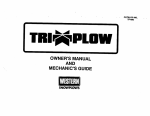
FORM NO.
13280
August, 1993
OWNER’S MANUAL
AND
MECHANICS GUIDE
CABLE ACTIVATED
ISARMATICB
MARK llla
PREFACE
Welcome to the growing family of WESTERN@ snowplow owners.
This manual will teach you how to operate and maintain your new
WESTERN snowplow and will provide safety information. Please read
this manual carefully and follow its recommendations.
When service is needed, your local Western distributor knows your
plow best. Return your snowplow to the distributor for maintenance
service or any other assistance you may require. We have enclosed in
your owner’s manual packet a “Report Card” for your use.
Your WESTERN Snowplow ISARMATICXB Mark llla Hydraulic Unit has
a serial number. Record this serial number and keep it in a safe place
so that you can refer to it if needed.
Before using your WESTERN snowplow, make sure your vehicle is
equipped with all vehicle manufacturer’s and Western recommended
options for snowplowing.
AFETY NOTE: Whenever you see this symbol, it notes a SAFETY WARNING. To avoid
serious Injury to your&f
or others, follow all
warnings.
Read this manual and plow labels
Western offers a one-year limited warranty for all snowplows and accessories. See separately printed page for this important information,
Western does not warranty non-Western service parts or accessories
or any damage caused by the use of these unauthorized items.
The following are registered@ or unregistered” Trade Marks of
Douglas Dynamics, Inc.
WESTERN@
ISARMATIC@
Hydra-Turn@
UniMount@
Roll-Action TM
PRO-GUARD”
TABLE OF CONTENTS
OWNER’S MANUAL
Make-up of the Snowplow
Blade . . . . . . . . . . , , . . . . , , , . . . . .
A-Frame & Quadrant , . , . , . 1 . . . . . , , .
Lift-Mount . . . . . . . , , . . . . . . . . . . . .
Assembly Diagram . , , , , , . . . , . . . . , ,
Hydraulic Power , , . . . . . . . . . . . . . . . ,
Angling
IllaControi 1 1 1 1 1 1 1 1 1 1: 1: 1 1 1 1 1 1 1 1
Light Kit . . . . . . , , , . , . . . , . , . . . . .
Mounting Snowplow to Vehicle . . . . . . . . . . . .
Operating Your Plow . . . . . . . . . . . . . . . . . .
Controlling The Blade ...................
Parkina with Plow Attached ................
Transporting Plow ......................
Plowing Snow ..........................
General Instructions ....................
Special Snow Conditions .................
Hard-Packed Snow ..................
Deep Snow ......................
Clearing Driveways ....................
Clearing Parking Lots ...................
Removing Snowplow & Storage ................
.
.
.
.
.
.
.
.
.
.
.
.
.
.
.
.
.
.
.
.
. :
. ;
. 9
. 10
1 1 1 1 . 11
. . . . * 12
. . . . . 13
. . . . . 14
. 14
. 15
* 15
. 16
. 16
. 16
. 16
. 16
. 17
. 17
. 18
OWNER’S
MANUAL
(Continued)
Maintenance
..........................
Pre-Season
Check
....................
..................
Regular
Maintenance
Disc Shoe Adjustment
................
Cutting
Edge .....................
Trip Sorina Adiustment
...............
PRO-GUARD”
Blade Finish .........
Black Iron Mount Parts - Powder Coated
Hydraulic
System
....................
Oil Level
.......................
Annual Fluid Change
................
System
Capacity
...................
Packing
Nut Adjustment
...............
...............
Pump Inlet Filter Screen
Emergency
Parts .....................
MECHANICS
Theory
MECHANICS
or ‘Painted
19
19
19
19
20
20
20
20
20
20
20
21
21
21
21
GUIDE
of Operation
......................
Electrical
.........................
Raising Plow .......................
Lowering
Plow .......................
Right or Left Plow Angling
................
Cushion
Valves
......................
GUIDE
(Continued)
................
Troubleshooting
Guide
Safety Rules ......................
................
Before You Begin
Personal
Safety
.................
....................
Ventilation
Fire and Explosion
...............
..................
Battery Safety
Hydraulic
Safety .................
..................
General
Information
A
Pump Pressure
Test ...............
B
Relay Test ....................
C
Cushion
Valve Adjustment
...........
D
3 Way Valve Lever Travel
............
E
4 Way (Angle) Valve Lever Travel &Adjustment
F
3 Way (Raise-Lower)
Valve Adjustment
....
25
.z
.26
. 26
.26
. 27
. 27
.26
.z
. 31
32
PARTS DIAGRAMS
22
23
23
23
24
24
Sub-Compact
& Compact
Plow Parts Diagram
............
Standard
Plow Parts Diagram
..............
PRO-PLOW
Parts Diagram
..........
Heavyweight
Plow Parts Diagram
...
MAKE-UP OF THE SNOWPLOW
BLADE
BLADE ACCESSORIES
The blade on your new WESTERN@ snowplow is constructed of
heavy gage steel. To increase rigidity and strength, the blade is reinforced with several vertical ribs, The top edge is rolled for added
strength and improved appearance,
The exclusive Roll-Action TMblade is designed to roll snow ahead and
to the side instead of just pushing snow. This action means you can
move more snow and move it faster using less power, saving fuel and
reducing wear and tear on both vehicle and plow.
The blade has a replaceable high-carbon steel cutting edge bolted to
the bottom. This cutting edge is reversible to equalize wear and
should be replaced when it is worn to the bottom edge of the blade
(See Regular Maintenance and Adjustments.)
The blade also features large, adjustable disc-type skid shoes. These
rotate 360” for longer wear and better blade flotation over all surfaces.
For severe service, heavy duty disc shoes are available from your
local Western distributor.
Your new blade is protected with PRO-GUARD’” - a baked-on powder finish that resists cracking, corrosion, scratching and rust. The
PRO-GUARD’” coating - many times thicker than paint-will maintain
its luster and glossly good looks longer than any other snowplow
blade finish in the industry. lt can be touched up when necessary.
Blade guides with replaceable flags are furnished with your complete
snowplow. These help improve operator visibility and blade control.
- OPTIONAL
Snow Deflector - Optional snow deflector keeps snow off the
windshield and away from the radiator. The deflector improves
Roll-Action” and increases plow efficiency.
2
STANDARD
BLADE, QUADRANT
& A-FRAME
Blade Guide with Flag
Hook Chain
318 Grade 8 Bolt
To Mount
See Page 34 for Part Numbers.
PRO-PLOW BLADE,
QUADRANT & A-FRAME
Blade Guide with Flag
PRO-PLOW Blade
Hook Chain Here
LiR Channel WI
314 Bolts
PRO-PLOW
. Chain
: A-Frame
Cuttina-s- Edge,
VI
3/4 Bolt --I
Shoe Spacer
Heavy Duty Disc Shoe
See Page 35 for Part Numbers.
PRO-PLOW Medium A-Frame
4
HEAVYWEIGHT BLADE,
QUADRANT & A-FRAME
Blade
Guide
with
Flag
-I
Hook
Heavy
AASHO
Cutting
Duty
Duty
Here
Quadrant
Edge
Cotter
Heavy
Chain
Disc
Shoe
4
Pin
/I
“Q
3/8 Grade
8 Bolt
Heavy Duty A-Frame
‘age 36 for Part Numbers.
5
A-FRAME & QUADRANT
The quadrant is attached to the back of the blade with bolts and locknuts (pins on heavyweight blades) and heavy-duty trip springs. The
trip springs allow the blade to trip forward and ride over obstacles
such as low curbs, manhole covers, etc., without damage to the blade
or vehicle or injury to driver. The tension of the trip springs is adjustable. (See Regular Maintenance and Adjustments.)
The quadrant is attached to the triangular A-Frame with a pivot bolt,
which allows the quadrant and blade to swing right or left. Heavy 1”
diameter hitch pins are used to secure the A-Frame ears to the vehicle
mount. These hitch pins can’t be bent and will not shear in normal
operation, assuring a solid connection.
Ear
Quadrant
A-FRAME
6
& QUADRANT
ASSEMBLY
LIFT-MOUNT
Western
vehicles.
semblies
has designed
custom
lift-mount
assemblies
Due to differences
between
vehicle models,
are generally
not interchangeable.
for most
lift mount
as-
The mount is fastened
to the underside
of the vehicle frame and
provides
the primary
connecting
point between
the snowplow
and the
vehicle.
The lift, welded
to the mount at the front of the vehicle,
provides
the supporting
framework
for the hydraulic
unit.
Frame
LIFT-MOUNT
7
ASSEMBLY
ISARMATICQ MARK llla ASSEMBLY DIAGRAM
Lock
Spool
Grommets
. . .
(Hydraulic
..m .
,..I
Unit)
8
HYDRAULIC
12 Voli
Cable.
POWER
The WESTERN ISARMATKB Mark llla System provides a fast and
uniform speed of lifting and angling. The Extra Duty System (i-112”
Ram) raises the blade in 2 seconds and angles side to side in 4
seconds. The Heavy Duty System (2” Ram) raises the blade in 4
seconds and angles side to side in 8 seconds.
The ISARMATICB Mark llla reservoir should be filled with automatic
transmission (ATP) fluid (Mobil One or Texaco 1537 Aircraft Hydraulic
Oil may be used for low temperature operation). Push lift channel all
the way down. Remove fill plug (behind motor). Fill reservoir only
through the fill opening (it is designed to prevent over-filling). Reservoir is full when the oil level reaches hole threads. Replace fill plug.
SYSTEM
CAPACITY
All ISARMATICB Mark llla Unit Reservoirs - l-1/2 quarts.
ISARMATICB Mark llla Extra Duty (l-1/2” Ram) with lo” Hydra-Turn@
Rams - 2-l/8 quarts.
ISARMATICB Mark llla Heavy Duty (2” Ram) with 16” Hydra-Turn@
Rams -2-3/4 quarts.
\ 44Vay
ISARMATKX MARK llla
(Hydraulic Unit)
9
Valve
HYDRA-TURN@ ANGLING
when it is being raised, lowered, or angled.
Do not stand between the vehicle and blade or
directly in front of blade. if the blade hits you or
drops on you, you could be seriously injured.
Hydra-Turn@ power angling gives you full control of the plow from
within the cab of the vehicle - you’ll never have to get out in the
snow to change the angle of the blade. Two single acting hydraulic
rams hold the-blade atihe desired
angle. The rams are operated by the
llla control.
The ISARMATIC@ Mark llla 4-way
valve manifold has two cushion valves built in to prevent damage to the
blade or vehicle if obstacles are hit.
When the force against the blade
causes pressure in an extended ram
to exceed set limits, the cushion
valve opens allowing oil to escape
and the ram plunger retracts.
Hydraulic Quick Coupler
Hvdraulic Pressure Hoses
N
OTE: In the event of HydraTurnBangling
failure, place a
519” bolt thru the holes in the AFrame I quadrant. This will hold
the blade in position until the
problem
is corrected.
For
heavyweight Hydra-Turn@ failure,
use Part Number 93015 Toggle
Pin.
/,u
Quadrant
HYDRA-TURN@
/
ANGLING
vl
10
Packing Set
,’
A Hydraulic
MA CONTROL
The llla control assembly controls raising, lowering and angling the
blade left or right, The sliding lock spool allows the control to be
secured in the neutral position to prevent blade movement. The
blade can be moved without the vehicle ignition switch being in the
“on” position.
lowered
or angled
anytime
Typical Dash Brackel
the control
pushed Into the center of the cross slots when
the plow Is nol In use. Accidental movement of
the plow could result In serious Injury.
engaged when
mounted plow
Is nol In use
WESTERN@ control cables are built for the most brutal winters.
They’re designed with stainless steel wire, conduit lined with high density polyethylene and permanently lubricated for low temperature
operation.
During the off season, the llla control lever can be removed by unscrewing the lever from the control. Store lever in glove box of
vehicle.
!Swltch Location
rotated within slots
11
LIGHT KIT
Replacement 2E1 Seal Beam headlamps (P.N. 49297) are available
through your local Western distributor.
The headlamp kit includes a set of rectangular dual-beam halogen
headlamps plus combination park and turn signals.
A patented pre-wired harness with plug-in module requires no headlamp wire splicing. Lights conform to federal safety standards.
Use plow headlamps ONLY when plow is attached. Use vehicle headlamps when plow is NOT attached.
ARNING:
Before traveling,
C
AUTION: Lights may be damaged
car washes.
position blade
not change blade position while traveling.
LOW PROFILE LIGHT KIT
12
by brush-type
automatic
MOUNTING
N
SNOWPLOW
TO VEHICLE
ote: Lift-mount assembly must already be installed.
WESTERN@ snowplows are easy to mount and remove from your
vehicle. The blade, quadrant and A-frame are usually removed and
stored as a complete assembly.
1. Position your vehicle close behind plow so that the A-frame
ears are approximately in line with coupling lugs on mount.
2. Hook chain to lift channel.
pling Lugs
Pin
ARNING: Inspect plow components and
bolts for wear or damage whenever mounting or removmg the plow. Worn or damaged components could permit plow to drop unexpectedly.
’ Hairpin Dotter
7. Move llla control lever to lower position. Leave lever in detent
position (float position).
8. Push lift channel all the way down. Pull the chain tight and
hook it to the lift channel. After chain is hooked, it will have the
correct amount of slack for plow to “float” (move up and down
to follow the contour of the surface being plowed).
9. Move the control lever to raise, lower and angle plow in both
directions to make sure all systems are in working order.
10. Move plow light switch from vehicle lights to plow lights.
3. Pull the lock spool up out of the cross slots in the llla control.
4. Move llla control lever to raise and raise lift channel until Aframe ear holes align with coupling lug holes on mount.
ARNING: Never put a finger in A-frame ear
or mount coupling lug holes to check align-
ARNING:
Keep well clear of the blade
when lt is being raised, lowered, or angled.
5. Insert hitch pins and hairpin totters as shown.
6. Connect hoses between hydraulic unit and Hydra-Turn@ rams
on each side of A-frame.
N
OTE: Temperature changes may cause a pressure build-up
within the Hydra-Turn@ rams that prevents recoupling of the
hoses. lf this occurs, place a clean rag over the male coupler and
lightly tap the ball on a block of wood to release the pressure.
1
13
directly in front of blade. lf the blade hits you or
drops on you, you could be seriously injured.
OPERATING
CONTROLLING
The llla control
THE BLADE
operation
Pull the lock
spool
RAISE:
LOWER
YOUR PLOW
(Float):
is
up out of the center
of the cross
slots.
Move
blade
llla control
until blade
lever UP (forward)
to raise
has reached
desire height.
Move
(float)
llla control
blade.
lever
DOWN
(back)
to lower
ANGLE
LEFT:
Move llla control lever to the LEFT to angle
blade to the left until blade has reached
desired
angle.
ANGLE
RIGHT:
Move llla control lever to the RIGHT to angle
blade to the right until blade has reached
desired
angle.
LOCK
BLADE
A
as follows:
IN POSITION:
Push
cross
lock spool
slots.
down
into center
position
has a detent to allow
on the surface being plowed.
the plow to
of
float (move up
C
autlon: DO NOT hold lila control lever In “raise”, “angle left”
or “angle rlghr’ posltlon longer than 5 seconds beyond
hydraulic function demand. To do so Increases battery drain and
could resutt In motor burn-out.
The llla control
is equipped
with a manual
lowering
or movement
of the blade, Push
the center of the cross slots to prevent
the
Pull the lock spool up out of the cross slots
spool should be engaged
whenever
plow
ARNING:
The blade can be raised,
lowered, or angled anytlme the control
lever is moved. Always keep the lock spool
pushed Into the center of the cross slots when
the plow Is not In use. Accldental movement of
the plow could result In serious Injury.
During the off season, the llla control
lever can be removed
by unscrewing
the lever from the control.
Store lever in glove box of vehicle.
The lever should be moved
all the way into the desired
position
smoothly
and without hesitation,
Always return the lever to the neutral
position
except when float is desired.
The “lower”
and down)
W
lock to prevent
accidental
the lock spool down into
plow from being moved.
to operate
the plow. Lock
is not in use.
14
PARKING WITH PLOW AlTACHED
Whenever
you
park your
vehicle,
lower
blade
to the ground.
vehicle is parked. Temperature
2.
Adjust
3.
4.
5.
PLOW
OTE: These lnstructlons
from plowing jobs.
front of vehicle.
1.
Raise
for maximum
plow
light illumination.
ARNING: Your vehicle must be equipped
with plow headllghts and dlrectlonal lights.
ETssure the plow lights are operating properly
betore traveling.
Adjust
A
A
Nand
height
W
changes
blade to drop unexpectedly
or damaging
hydraulic components.
Fallurs to do this can
result in serious injury.
TRANSPORTING
blade
are for drlvlng short distances to
For long trips, remove plow from
N
Move
blade
blade
to straight
W
lock spool
in place.
position.
ARNING: Make sure blade does not block
headlight beams.
down
into the center
of the oross
slot to lock
W
ARNING:
Never exceed posted road
speeds. Under bad weather condltlons or
when driving on uneven surfaces such as rallroad tracks or bumpy roads reduce speed.
L
Monitor vehicle operating
temperature.
Overheating
is unlikely under normal driving
conditions,
but occasionally
the plow
may be positioned
where it deflects
air away from the
radiator.
lf this occurs,
stop the vehicle and raise, lower or
angle the plow slightly to correct
overheating.
a
OTE: Only the drlvetr should be In the vehicle when the plow
Is attached durlng transport of vehicles wlth less than 314
ton rating.
blade.
15
PLOWING SNOW
SPECIAL SNOW CONDITIONS
GENERAL INSTRUCTIONS
-
1, Before plowing, make sure you know of any obstructions hidden beneath the snow, such as bumper stops in parking lots,
curbs, sidewalk edges, shrubs, fences, or pipes sticking up
from the ground.
IC
AUTION: To prevent damage to plow or vehicle, flag any
obstructions that are hard to locate.
I
2. Only the driver should be in the vehicle when plow is attached
for plowing.
-
ARNING:
Always wear seat belt when
plowing snow. A hidden obstruction could
cause the vehicle to stop suddenly, throwing you
3. Plow during the storm rather than letting snow accumulate.
ARNING: Never plow with head out of the
vehicle window. Sudden stops or protruding objects could cause severe neck or head
4. When you are stacking snow, begin raising the blade as you
come close to the stack. This will let the blade with its load
ride up onto the stack.
C
AUTION: Never pile snow with the blade angled more than
halfway or the bumper could be damaged.
16
Hard-packed Snow
1. Praise the disc shoes so that the cutting edge comes into
direct contact with the pavement. (See Regular Maintenance and Adjustments.)
2. Use lowest gear to place maximum power behind cutting
edge.
3. An angled blade is more effective to remove hard-packed
snow.
Deep Snow
1. Shear off top layers by plowing with the blade raised 3 to
4 inches for the initial pass.
2. Bite into the edges using only partial blade width until job
is cut down to size for full blade plowing.
Rule of thumb:
6” snow may be plowed with entire blade width,
9” with 3/4 blade,
12” with l/2 blade.
Experience and “feel” are the best guides.
3. When plowing deep snow, be sure to keep vehicle
moving.
4. Secure ballast behind wheels for better traction.
Recommended ballast for:
full-size pick-ups, 500-700 Ibs.
compact pick-ups, 300 Ibs.
5. For increased traction use tire chains.
I
i
CLEARING
CLEARING PARKING LOTS
DRIVEWAYS
1. Clear areas in front of buildings first. With raised blade, drive
up to building. Drop blade and “back-drag” snow away from
buildings. When snow is clear of buildings, turn vehicle
around and push snow away from buildings towards outer
edges of lot.
2. Plow a single path down center in long direction.
3. Angle plow toward the long sides, and plow successive strips
lengthwise until area is cleared and snow is “stacked” around
outer edges.
4. If snow is too deep to clear in above manner, clear main traffic
lanes as much as possible.
1. Head into drive with angled blade and plow snow away from
buildings. Widen drive by rolling snow away from building.
2. If building is at end of driveway, plow up to within a vehicle
length of building. Then push as much snow as possible off
driveway.
i. With raised straight blade, drive through remaining snow to
building. Drop blade and “back-drag” snow away from building at least one vehicle length. Repeat if necessary.
4. Back vehicle to building door and plow forward toward street,
removing remaining snow from driveway. Check municipal ordinances for disposal of snow.
17
REMOVING SNOWPLOW 81STORAGE
1.
Lower
the plow to the ground
(keep
tension
on chain).
Move
6.
Unhook
chain.
ARNING:
Inspect plow components
and
ARNING: Keep hands and feet clear of
blade and A-frame when removing or
mounting plow. Moving or falling assemblies can
2.
Disconnect
hose
Turn@ rams.
couplers
curb-side
ram.
between
A.
Connect
driver-side
ram hose
B.
Loop hydraulic
unit hose
couple hose into manifold
hydraulic
unit and Hydra-
into the quick
around
quick
coupler
the lift assembly
coupler.
on the
Pull hairpin totters
from hitch pins at rear of A-frame
and
remove
hitch pins. After disassembly,
replace hitch pins and
hairpin totters
in A-frame
ears for ready access when reinstalling plow.
4.
Move
5.
Push the lift channel
all the way down. Leave
down position
to protect
lift ram from rusting
the llla control
lever
to lower
(float)
position.
lift channel
and pitting.
Move
center
llla control
lever to neutral.
of cross slots.
6.
Move
plow
N
and
This will protect
the quick coupler
ends and keep foreign
matter out of the quick couplers
while the snowplow
is off
the vehicle.
3.
7.
in
light switch
from
plow
Slide lock spool
lights
to vehicle
down
into
lights.
OTE: For long-term storage, grease exposed chrome surfaces of the Hydra-Turn@ rams to prevent rust.
C
AUTION: To prevent the shock absorber on the PRO-PLOW
A-frame from collecting water, store plow with A-frame
horizontal.
During the off season,
the llla control lever can be removed
by unscrewing
the lever from the control.
Store lever in glove box of vehicle.
MAINTENANCE
REGULAR MAINTENANCE
PRE-SEASON CHECK
Before the snow flies, check your equipment and make sure it’s ready
for action. Here’s a checklist for making sure your equipment is set
for the snowplowing season 1. inspect hydraulic system for leaks and cracked or damaged
hoses. Check oil level (push lift channel all the way down).
2. Inspect all parts of plow and mount system. Replace worn or
defective parts.
3. Clean all electrical connections, including grounds.
4. Inspect and test your battery and recharge or replace if neoessary. Suggested MINIMUM vehicle electrical system: 70 amp
hr./550 CCA battery, 55 amp alternator.
5. Check mounting of snowplow to vehicle and tighten any loose
fasteners.
8. Repaint mountings with rust resistant, high grade enamel.
Touch-up blade with WESTERN@ red paint available in
aerosol or quart can.
7. Check windshield wipers, heater, and vehicle and plow lights
for proper operation. Check that plow headlights are properly
aimed. Plow headlights should be aimed with plow attached
and in raised position,
8. Secure ballast behind rear wheels. Suggested ballast for:
full size pick-ups is 5GfI-700 Ibs.,
compact pick-ups is 300 Ibs.
AND ADJUSTMENTS
ARNING:
To prevent injuries, always
lower snowplow
to the ground when
parked. Always remove snowplow before serused.
Failure to do this can result in serious
Your WESTERN@ snowplow is designed for rugged, dependable service. But like the vehicle on which it is mounted, it needs a certain
amount of regular care and maintenance. Check the following before
and frequently during the plowing season:
- Make sure all fasteners, mounting bolts, hydraulic and electrical connections are tight.
- Check all plugs and seals for oil leaks. Repair as necessary.
- Disc Shoe Adjustment
Recommended shoe adjustments:
1. For gravel surfaces - bottom surface of shoe should be
l/2” below cutting edge.
2. For hard surfaces (concrete or asphalt) - bottom surface
of shoe should be even with cutting edge.
ADJUSTMENT PROCEDURE
1, Raise blade and place on blocking.
2. Remove linch pin and slide shoe down out of bracket.
3. Remove one or more washers from shoe stem and
reinstall shoe into bracket.
4. Place removed washers onto shoe stem above bracket,
5. Install linch pin. NOTE: Do not discard any washers.
19
MAINTENANCE
(Continued)
REGULAR MAINTENANCE
-
-
-
-
AND ADJUSTMENTS
(Condt.)
Cutting Edge
To equalize wear, cutting edge can be reversed. Replace cutting edge when worn to the bottom of blade sheet.
1. Raise blade and place blocking under A-frame.
2. Remove cutting edge, and turn end for end.
3. Reinstall.
Trip Spring Adjustment
To adjust trip spring tension, adjust the eyebolts located at
the top of the blade.
1. Loosen locknut (nut closest to spring).
2. Tighten adjusting nut (nut closest to plow) until coils
begin to separate. When tension is properly adjusted, a
sheet of paper should pass between the second and third
coils.
3. Tighten locknut.
PRO-GUARD m Blade Finish
lf the PRO-GUARD’” powder coated finish is nicked or
scratched, repair the blade surface with WESTERN@ red paint
in aerosol or quart can.
Black Iron Mount Parts - Powder Costed or Painted
Parts should be cleaned and repainted as required.
HYDRAULIC SYSTEM
-
Oil Level
Push lift channel all the way down. Remove fill plug (behind
motor). Pill reservoir only through fill opening (it is designed
to prevent overfilling). Reservoir is full when the oil level
reaches hole threads. Replace fill plug.
-
Annual Fluid Change
IMPORTANT: Change fluid at the beginning of each piowIng season.
1. Remove drain plug located in the bottom of the right front
corner of the reservoir (see diagram).
2. Completely drain the hydraulic reservoir.
3. Refill through fill hole with new automatic transmission
fluid (ATP). (Mobil One or Texaco 1537 Aircraft Hydraulic
Oil may be used for low-temperature operation. DO NOT
mix different types of oils.)
-
System
-
Capacity
All ISARMATIC@ Mark llla Unit Reservoirs - l-1/2 quarts.
ISARMATICXB Mark llla Extra Duty (l-1/2” Ram) with 10”
Hydra-Turn@ Rams - 2-l/8 quarts.
ISARMATIC@ Mark llla Heavy Duty (2” Ram) with 16”
Hydra-Turn@ Rams -2-314 quarts.
AUTION:
through
Fill reservoir
through
motor/pump
opening.
fill hole
Overfilling
ONLY.
Never
can damage
Packing
Nut Adjustment
Periodically check lift ram and Hydra-Turn@ ram packing nuts
for tightness. lf packing nuts are loose or leakage appears
while lifting or angling plow, tighten not more than l/4 turn
after you feel packing nut contact the packing.
C
fill
the
Do not overtighten
AUTION:
packing
nut.
Packings not used for a period of time may show signs of oil
weep. This will usually stop after use.
-
Pump
inlet
Fiiter
Screen
Clean the pump inlet filter screen whenever the pump is
removed. lf the screen is damaged, replace it. Torque die-cast
pump mounting capscrews to 175185 in.-lbs, motor mounting capscrews to 15120 ft.-lbs.
Nut
EMERGENCY PARTS
We suggest that you keep a WESTERN@ Emergency Parts Kit
#49205 in your vehicle for emergency use.
We recommend the following additional items be kept in your vehicle.
1 - 56131 K Relay - Cable Hydraulic System
1 - 19” Adjustable Wrench
1 - Medium Screw Driver
1 - Pair of Pliers
1 - Quart Automatic Transmission Fluid (ATF)
Pump inlet
Fiiter Screen
iSARMATiC@
(Hydraulic
Mark
Unit)
iiia
Always use WESTERN@ designed and tested replacement parts.
21
MECHANICS
GUIDE
Three of these functions (RAISE, ANGLE RIGHT, ANGLE LEFT) are accomplished by electrical and mechanical means. The fourth (LOWER)
operates only by mechanical means (motor does not run).
THEORY OF OPERATION
The ISARMATICB Mark llla Hydraulic System performs four functions:
RAISES the snowplow
LOWERS the snowplow
ANGLES snowplow RIGHT
ANGLES snowplow LEFT
ELECTRICAL
When the llla control is in the RAISE, LEFT (L) or RIGHT (R) position,
contacts inside the control are
grounded through the control
cables to the hvdraulic unit.
That complete; the motor relay
Grounded Through Engine Block
(primary) circuit, energizing the
or By Cable Direct to Battery
-------------------relay coil. The energized relay
coil causes the contacts inside
the motor relay to close, completing the battery/motor
(secondary) circuit. A direct,
low resistance current path is
now available to energize the
electric motor. Current flows
Motor R&y
from the battery, through the
contacts in the motor relay, the
2
1
motor, the motor frame ground
screw, the ground cable and
back to the battery.
l-l
+12VoR
rlBattery
I llla I I
Ground (Through Control Cables)
3 Position/
Switch
Control
1
----
1
Primary (Low Current)
Secondary (High Current)
Jumper Wire & Second Small Terminal
ELECTRIC SCHEMATIC
22
RAISING PLOW
LOWERING PLOW
Moving the llla control to the RAISE position activates
the motor relay
(and motor) and the cable moves the shuttle into the lift valve.
This
closes the passageway
to the reservoir
and directs flow from the
pump outlet to the lift ram. Oil passes through
the 4-way valve and
into the 3way valve. lt flows around the shuttle stem and pushes the
check valve ball off its seat. lt then enters the lift ram, pushing
the
plunger
(and the snowplow)
up.
Moving the llla control to the LOWER
(float) position
moves the shuttie to push the check valve ball off its seat. This opens a passageway
from the lift ram to the reservoir.
Weight of the snowplow
collapses
the ram, forcing
oil past the open check valve and shuttle, back to the
reservoir.
Note that the pump does not operate
when the plow is
being lowered.
4-Way
Valve
Reservoir
LOWERING
RAISING PLOW
23
PLOW
RIGHT OR LEFT PLOW ANGLING
BY 4-WAY VALVE
LEFT (Fig. 6) The rotor
nections
of Hydra-Turn@
RIGHT (Fig. A) The rotor is rotated 45” clockwise
so the recessed
pockets
provide
passages
between
the pump supply and left HydraTurn@ ram and the reservoir
port. Oil from the pump flows through
the 4-way valve and enters the left Hydra-Turn@
ram. As the ram extends, the plow angles to the right, As the plow angles, the right
Hydra-Turn@
ram collapses,
pushing
oil through
the 4-way valve and
past the shuttle in the 3-way valve to the reservoir.
CUSHION VALVES (2) (Fig.C)
While plowing,
oil is trapped
in the extended
Hydra-Turn@
ram. When
the blade meets an object, pressure
rises in the extended
HydraTurn@ ram. As pressure
in the ram exceeds
the spring force holding
the checkball
against the seat, the
cushion
valve ball unseats
allowing
oil to
flow to the collapsed
ram. The blade
angles in the opposite
directions
preventROTOR
RECESSED
-.-ing damage
to the hydraulic
system
and
POCKETS
vehicle.
4 WAY VALVE
/
RETURN
OIL FROM COLLAPSINGCYLINOER
ROTOR
c4lown I"
angle right
WSmOnl
RESERVOIR
PORT
II
F"i.C
ANGLING
TO PASSENGER
SUPPLY
OIL TO EXTEND
CYLINDER
SUPPLY
OIL TO EXTEND
CYLINDER
LEFT
SIDE CYLINDER
ROTOR
(Shown I"
"WRal
poSI1Km~
ROTOR
(shown I"
angle Ien
poSl,lO"J
RESERVOIR
PORT
VALVES
TO DRIVERS
RESERVOIR
PORT
SIDE CYLINDER
PLOW
RETURN
ANGLING
AND
CUSHION
is rotated counterclockwise
reversing
the conrams, pump supply,
and reservoir
port.
VALVES
24
OIL FROM COLLAPSING
CYLINDER
TRnl
FSHfbnTlNC2
. ..------..--...m- JRI
llla
CONTROL
POSITION
PROBLEM DESCRIPTION
Angle
Blade will not angle or angles
too slow. Time: 4 seconds;
(8 seconds - Heavy-Duty)
Raise
Neutral
Neutral
Angle
DEFINE PROBLEM AND FOLLOW STEPS BELOW.
Check lf Check
motor
oil
runs, lf
level.
Blade will not raise or raises not, see B (page
too slow. Ttme: 2 seconds; (4 (page 29) 20)
seconds - Heavy-Duty)
Blade will not remain angled
while plowlng.
Motor continues to run In
neutral.
Blade lowers in neutral.
Lower
Blade lowers too fast.
Lower
Blade will not lower or lowers
too slow.
All
functions
slow.
see A,
(page 28)
Verify 4-way
valve lever
travel. See E
(page 31)
Verity 3-way
t,‘,$
EirD
(page 30)
Check disconnect
couplers &
hydraulic ram
nuts.
Remove pump.
Check l#l ram clean filter SCreel
Adjust lift valve
packing nut
in. See Fl
adjust. See Gen.
(paw 32)
Info. (page28)
Adust lift valve
out. See Fl
(paw 32)
Adjust cushion valves. See C (page 30)
Disconnect llla
Control wire
from motor
relay.
Blade raises while angling.
Neutral
CXJIDF
w-.-m
lf motor runs, motor relay Is shorted. Replace
motor relay. lf motor stops, short is In primary (Illa
Control) circuit. isolate and repair.
Adust lift valve (out). See Fl (page 32)
Verify 3-way
valve lever
travel. See D
(page 30)
Remove check valve.
Adjust check valve
Inspect O-ring 8 seat. See
(out). See F2 (page 32)
Service Manual.
Check lift ram packing
Adjust check valve (in). nut adjustment. See Gen.
See F2 (page 32)
Information (page 28)
25
FURTHER TROUBLESHOOTING
REQUIRES THE USE OF TEST
EQUIPMENT.
SEE AUTHORIZED WESTERN
DISTRIBUTOR
OR
SEE WESTERNG HYDRALECTRIC’” TEST KIT AND/OR
WESTERN SERVICE MANUAL
OR
SEE WESTERN@ HYDRAULIC
SERVICE SCHOOL VIDEO
SAFETY RULES
VENTILATION
AA
ARNING: Read all instructions, including
safety information before pertorming any
service or maintenance on your snowplow.
A
BEFORE YOU BEGIN
death. Never operate vehicle in an enclosed
area without venting exhaust to the outside.
lf you work on your vehicle or plow in a garage or other enclosed
area, be sure to vent exhaust gas directly to the outside through a
leakproof exhaust hose.
j 1, Park the vehicle on a level surface, place shift lever in PARK or
NEUTRAL, and set parking brake.
2. For most service procedures, leave the hydraulic components
on the vehicle.
A
ANGER: Vehicle exhaust contains deadly
carbon monoxide (CO) gas. Breathing this
FIRE AND EXPLOSION
when it is being raised, lowered, or angled.
Do not stand between the vehicle and blade or
directly in front of blade. if the blade hits you or
A
PERSONAL SAFETY
1. Wear only snug-fitting clothing while working on your vehicle
or snowplow. Do not wear jewelry or a necktie. Secure long
hair. Be especially careful near moving parts such as fan
blades, pulleys, and belts.
2. Wear safety goggles to protect your eyes from battery acid,
gasoline, and dust and dirt from machinery.
3. Avoid touching hot surfaces such as engine, radiator, exhaust
pipes, and hoses.
4. Always have a fire extinguisher rated for flammable liquids
and electrical fires (rated BC) handy.
W
ARNING: Gasoline is highly flammable
and gasoline vapor is explosive.
Never
smoke while working on vehicle. Keep all open
fiames away from gasoline tank and lines. Wipe
up any spilled gasoline immediately.
Be extremely careful when using gasoline. Do not use gasoline to
clean parts. Store only in approved containers away from sources of
heat or flame.
26
BATTERYSAFETY
HYDRAULIC
ARNING:
Hydraulic oil under pressure
can cause skin injection injury. if left untreated, these injuries can resuit in amputation
or death. if you are injured by hydraulic oil, get
gases tha can explode if touched by spark
or flame. Cover top of battery with electrically
non-conductive
material to keep sparks from
testing operations away from battery gases.
1.
Never lay tools or equipment
on the battery.
You could accidentally
ground the POSITIVE
(+) battery terminal,
resulting
in electrical
shock or burns or damage
to the vehicle or equipment.
2.
Avoid contact
with battery
and burn holes in clothing.
3.
Always disconnect
replacing
electrical
battery cables.
acid,
the battery
components
lt can burn
ground
such
before
SAFETY
your eyes or skin,
removing
or
relay or
as the motor
27
1.
Always
inspect hydraulic
components
Replace any damaged
or worn parts
2.
lf you suspect
a hose leak,
it. Use a piece of cardboard
and hoses
immediately.
DO NOT use your
or wood.
hand
before
use.
to locate
GENERAL INFORMATION
A
Most service can be performed
with the hydraulic
unit left on the
vehicle.
This should be done whenever
possible
because
it permits
evaluation
of the entire system
(vehicle electrical
system,
cables,
llla
control,
etc.) as well as saving considerable
time.
POOR CONDITION
TEST RESULTS.
A
W
ARNING:
DO NOT stand between the
vehicle and blade or directly in front of
blade when it Is being raised, lowered or angled.
Clearance between vehicle and blade decreases
as blade is operated. Serious bodily injury can
result from blade striking a body or dropping on
feet or hands.
PUMP PRESSURE TEST
OF BATTERY
1.
Disconnect
lift chain
2,
Install 2000
Manifold.
PSI minimum
3.
Move
4.
If pressure
llla Control
and hoses
to angle
WILL
gauge
into female
“LEFT”
and
Check Valve Adjustment
(3-Way Valve)
Seal Cable Entry to
Housing with 56195
Cable Sealant
Gauge/
Hydra-Turn@ 4-Way Valve
Cover Plate
N
Fastener
Torque
Pump Capscrews
Motor Capscrews
OTE Manufacturer assumes no liability for accidents or
damages notwithstanding
the fact that suggestions have
been followed.
28
- 175/185 In.Lbs.
- 15/20 Ft. Lbs.
INVALID
rams.
coupler
on Valve
read gauge.
pressure
lf pressure
is low, remove
pump, clean or replace
pressure
relief valve. (114 turn equals approximately
’ Min Radius
nds in Cables
CAUSE
to Hydra-Turn@
is 1650 - 1850 PSI, pump
PACKING NUT ADJUSTMENT - ISARMATIC 03 MARK llla or
HYDRAULIC RAMS lf leaking, tighten packing nut NOT MORE THAN
l/4 TURN AFTER YOU FEEL PACKING NUT CONTACT PACKINGS.
Over-tightening affects ram operation and packing Ilfe.
Cushion Valvesy
OR MOTOR
is “OK”.
filter and adjust
225 PSI.)
B
RELAY TEST
Condition - Motor does not run with llla control in “RAISE”, angle
“RIGHT” or “LEFT”. Battery has sufficient charge to start vehicle engine.
1. Disconnect lift chain and hoses to Hydra-Turn@ rams.
2. Check all electrical cables and connections including
grounds. Clean and tighten if necessary.
Step
AIW
ARNING:
Protect
top of battery,
sparks
from testing
operations
could cause
battery gases
to explode
causing
severe
eye or
body burns,
or other personal
injury.
Relay - Cable
Hydraulic
System
(Motor
Relay)
6. Use a jumper wire to connect small terminal with BLACK wire
on motor relay to the “NEG -” terminal of the battery. If
motor runs, problem is in llla control (primary) circuit. Check
for broken wire, loose connection or bent contacts in llla control. Check if llla control is grounded (through push-pull
cables). lf motor does not run...
4. Use a jumper wire to connect “POS +” terminal of battery to
small terminal with RED wire attached on motor relay.
Operate llla control to “FIAISE”, angle “LEFT” or “RIGHT”. lf
motor runs, check for broken or damaged red wire on relay. If
motor does not run.. .
6. Use heavy jumper cables to by-pass (jump) the two large terminals on top of the motor relay, If motor runs, replace motor
relay. lf motor does not run.. .
6. Remove motor and check pump shaft rotation. If tight, repair
or replace pump, if loose replace motor.
t
=
Ia
r
attery
Step4
-I
Step
3.
1
Black Wire
from
iiia Control
29
/
c
D
CUSHION VALVE ADJUSTMENT
Whenever
to threads
stems are removed,
apply
of stem before assembly.
DISASSEMBLY
anti-seize
compound
& INSPECTION
1.
Remove
cushion
valve stem. Use a magnet
spring spacer and spring.
Inspect
parts.
2.
Replace
3.
lf OK, place
lightly strike
NOTE:
4.
Stem
or grease
O-rings
or complete
assembly
ball on wooden
block,
stem with hammer.
can be bent
Reassemble
by not striking
components
to remove
3-WAY VALVE LEVER TRAVEL
1.
Disconnect
2.
Remove
3.
Move llla control
valve lever travel
4.
Lock llla control
neutral position
ball,
if damaged.
hold stem
hydraulic
3-way
hoses
and lift chain.
(rectangular)
cover.
between
“RAISE”
and positions.
in neutral.
as shown,
3-way
and
“LOWER”.
lever
should
Observe
be in the
seat on ball, and
squarely.
and adjust
per directions
ADJUSTMENT
1
Tighten
cushion
valve
is fully compressed).
stem
as much
as possible
2.
Rack off valve stem (rotate counterclockwise)
l-1/4 turns. This adjustment
will cause the
cushion
valve to open at approximately
3,500 PSI
(until spring
3-WAY VALVE
Valve
Cushion
Valves
Valve
LEVER TRAVEL
Stem
Stem
POSSIBLE
CAUSE OF INADEQUATE
VALVE LEVER POSITION
‘3
/
1.
Dirt, or ice buildup
2.
Cable
3.
Binding,
4.
Set-screw
not in groove
in cable.
5.
Lift valve
too far in (3-way
valve
Seal cable
30
TRAVEL
in enclosure.
disconnected
entries
kinked
OR INCORRECT
in valve
or broken
into housing
enclosure
cable.
or in llla control,
(8” minimum
only).
NOTE
with 55195
(See Fl)
Cable
Sealant.
radius)
E
4-WAY (ANGLE) VALVE
LEVER TRAVEL & ADJUSTMENT
1. Disconnect hydraulic hoses and lift chain.
2. Remove 4-way (5 sided) cover.
3. Move llla control between angle “RIGHT” and “LEFT”. Observe lever movement especially for EQUAL TRAVEL IN EACH
DIRECTION. If unequal, adjust cable per right diagram, this
page.
4. When travel is equal in both directions, lock ltla control in
neutral. 4-way lever may be in line or slightly down from the
indicated 3 point alignment in diagram.
increase
Right Angling
Speed
\
increase
I
emaie
Valve
Lever
Cable
End
Pin
3 Point
(Neutral
Alignment
Position)
4-WAY CABLE ADJUSTMENT
POSSIBLE
CAUSE OF INADEQUATE
VALVE LEVER POSITION
I
\
Angie
’
1.
2.
3.
4.
5.
450
Right v
41WAY VALVE LEVER TRAVEL
TRAVEL
OR INCORRECT
Dirt, or ice buildup in enclosure,
Cable disconnected in valve enclosure or in llla control.
Binding, kinked or broken cable. (8” minimum radius)
Set-screw not in groove in cable.
Cable out of adjustment or insufficient ring/rotor clearance
NOTE
Seal cable entries into housing with 56195 Cable Sealant.
31
F 39WAY (RAISE-LOWER)
SENSITIVE ADJUSTMENT
VALVE ADJUSTMENT
- MAX. l/8 TURN AT A TIME
Make adjustments with blade on ground and control in neutral. Stand back after
adjustment to avoid being pinched by blade while checking operation.
FI
W
ARNING:
DO NOT stand between the
vehicle and blade or directly in front of
blade when it is being raised, lowered or
angled. Clearance between vehicle and blade
decreases as blade is operated. Serious bodily
injury can result from blade striking a body or
dropping on feet or hands.
A
LIFT VALVE ADJUSTMENT
L
n
From initial adjustment below, using 118 turn increments, turn OUT (counterclockwise) lift valve until ‘RAW” does NOT function properly. Turn lift valve IN in 118
turn increments until unit is able to lift plow. Turning valve in more than 114 turn
beyond lifting point may slow angling speed.
F2
/
Tighten
Locknut
CHECK VALVE ADJUSTMENT
Hold check valve (hex socket wrench) while loosening or tightening locknut, To
prevent O-ring from “blowing out”, loosen locknut 114 turn maximum. Tighten
locknut maximum 1 Ft. Lb.
lf plow will not lower or lowers too slowly, turn check valve IN (Cw).
lf plow lowers too fast, turn check valve OUT (CCVV).
LIFT VALVE
t
INITIAL ADJUSTMENT
OR REMOVED)
(IF VALVES HAVE BEEN DISTRUBED
LIFT VALVE
Remove cable from pin and place valve lever in neutral position (See D). Turn lift
valve in until it is flush to the casting surface. Rotate lever to the RAISE position, It
should stop l/16” to l/8” from enclosure bottom (see D). If not, turn valve in or
out until this dimension is obtained. See Fl for final adjustment,
CHECK VALVE
Turn check valve in until threads are flush with thick locknut when nut is bottomed
on housing. (Early models with thin jam nuts -turn check valve in until three (3)
full threads protrude from the jam nut with jam nut bottomed on housing.) See F2
for final adjustment.
32
CHECK VALVE
SUB-COMPACT & COMPACT PLOW PARTS DIAGRAM
NOTE:
SEAL CONTROL CABLES
WITH 56195 CABLE
SEALANT
PC=Compsct Plow
PSC=Sub-Compact Plow
Knob IL Lever Assy 49016-&-
Lockswo, 49017
Knob & Lever
Short - 49
Blade Guide 59700
/-
Contact Strip
Ball Rstamer Chp
Cover
56026
49019
56028
1 &mom
Hex Nipple 255194
Cuttmg E&e Assembly
wth Bolts II Nuts
6 Ft. Sub-Compact
49069
6-l/2 Ft Compact
., ,.. 49066
O&) I
,-For Short A-Frame
PSC & PC ~~
I
Short L,ft Channel 60342
I Ilw--Li”ch pi
Relay. Cable Hydraulic
System 56131K
PSC 80856
PC 60036
karmatic@ Mark ItIe
ubc System 56135
mm& Mark Ma
a Duty Ssrwce Unit
ith 4W Valve 58139
Base Lug 25966
r Locknut 91338
Trip Sprmg 23039
PSC Shoe Assy 49
PC Shw Assy 49
H D. Shw Aaav 49071
loPtloni-k
,-TToSoleno,d
4.way Control
Valve 49020
PC 90155
Street Elbow 92210
Locknut 91336
carter Pm 91911
Rivet 93063 --f)
/
Hitch Pin
PSC 93031
PC 93026
lrDl” 91965
L
Male Elbow 92276
Short A-Frame
PSC 60649
PC 60202
Medwm A-Frame
PC go030
For Short A-Frame 60649 IPSCI
For M&urn A-Frame 80030 (PC)
cotter Pm 91911
D._.^. n*-_J
L
Cylinder Assy 56102
L
USE ONLY GENUINE WESTERN@ REPLACEMENT
33
For ShoR A-F&:
60202 IPC)
Groove Pm 92004
Rwet 93065
PARTS
STANDARD PLOW PARTS DIAGRAM
Blade Gu,de 59700
IlleControl
56018
Contact strip
Ball Retainer Clip
Bottom Cover
3w Cable 56035
Cutting Edge Assembly
with Bolts & Nuts
6~112 Ft. Standard
7 Ft. Standard
56026
49019
56028
\
49066
49070
I
Quick Coupler 25232
Capscrew 90159--i+'
For Medium A Frame
Box No. 60022 Qnlv
Medium Lift Channel 58;‘34
OR
iFor Short A-Frame
80x No. 60198 Onlv
Short Lift Channel $0342
t
H.D. Shoe Assy 49071
Llnch Pin 93010
Relay - Cable H
System 56131K
Capscrew
90132
linder Une 56104
Capscrew 90155
freet Elbow 92210
Locknut 91338
Packing Nut 2594.4
Packmg Set 25205
armatic@Mark llla
draulicS,stem 56135
armatic@Mark llla
tra Duty Service Unit
ith 4W Valve 56139
Ease Lug 0-Ring 25618A
Ease Lug 25968-
. GQ::;;g:;
Rivet 93063
99le Pin 93030 (Sen
-Lo
\
Piston 56105Packing Set
&Wiper 25205
C=Z
Halroin 9lS85
Male Elbow 92278
Cylinder Ass+ 561021
L
For Medium A-Frame 60030 Only
Cotter Pin 91911
Rivet 93063
OR
For Short A.Frame 60202 Only
Groove Pin 92004
Rivet 93065
USE ONLY GENUINE WESTERN@ REPLACEMENT
34
i
PARTS
!EoA:E: CONTROL
CABLES
WITH 56195 CABLE
SEALANT
PRO-PLOW PARTS DIAGRAM
Knob
x N”,
91416
/-Eye
Bolt
rTrip
PRO
cumng
Edge Ad”
9 Ft PRO-PLOW..
Wml
8 112 Ft PRO PLOW
8 Ft PRO PLOW
7 l/2 F, PRO PLOW
Duty
Shoe
Arr’y
4901
/Hex
Nipple
Lockspool
25519
acnmg N”f 25944
acklng
Set 25205
der ““,I
56104
cluadrant
6201
Locknut91337
Far
As’”
NOTE.
SEAL CONTROL CABLES
WITH 56195 CABLE
SEALANT
Locknut
Washer
49071-
9,338
91147
& capscrew
Piston E6105-
.
For PRO PLOW
Medwm
Cotter
PI” 91911
Rwet 93063
lfold
O-Rings
92210
90132
%x8,6
Gasket
55374
t
t-
A Frame
60324
Oniy
OR
For PRO PLOW Short A Frame
Groove P,” 92004
R,vet 93065
55252’
USE ONLY GENUINE WESTERN@ REPLACEMENT
35
49017
90493
Spring 23039
reet Elbow
Capscrew
capscrow
HBWY
PLOW
Bolts 4925,
and N”TS
49086
49089
49088
& Lever
Knob & Lever ASS y
Short - 49147
PARTS
60202
Only
PRO-PLOW
Short
A-Frame
Box No. 60315
50342
Shorr L,ft Channel
HFAVY
,.--.
.
WFIGHT
s---w---
A
PLOW PARTS DIAGRAM
_
__
-.
/,$&/
\i\
Knob 6, Lever Ass’V490167
~onrat Strip
Ball Retainer Clip
80tt0m Cover
3, Cab,
4w Adjust
BladeGuide 59700
\B
56026
49019
56028
Locknut 91338
I/
caprcrew
90161
iff Channel 49007
ew 90160
AASHO Cuttmg Edge A& With Bolts “5:;,t;
9Ft,He*“yD”ty
,,,....,..,
,..
58818
10 Ft. Heavy Duty
Ou,ck Coupler 25232
rPackinS Nut 25948
p
v--
1 TogglePin 93015/,-
,_“..
=-..~
Cylinder Unit 25949
4” Motor 56133
Isarmatic”Mark llla H~WV Duty
Hydraulic System 56140
lrarmatic@Mark llla Heavy Duty
Service Unit 56097 with 4W Valve
NOTE:
SEAL CONTROL CABLES
WITH 56195 CABLE
SEALANT.
street Eli Spl. 92208
Manifold Gasket 55374
kkavy Duty A-Frame 49004
Male Elbow 92276
USE ONLY GENUINE WESTERN@ REPLACEMENT
36
PARTS
-
bb
A DIVISION
OF DOUGLAS
DYNAMICS
INC.
Western
reserves
the right under its Product
Improvement
Policy to change
construction
or design details and furnish
equipment
when so altered without
reference
to illustrations
or specifications
used herein. The following
are registered8
and
unregistered”’
Trade Marks of Douglas
Dynamics,
Inc: WESTERN@,
ISARMATICXB,
Hydra-Turn@,
UniMount@,
Roll Action’“,
PRO-GUARD”.
Western
and the vehicle manufacturer
may require
and/or recommend
optional
equipment
for snow removal.
See Western’s
installation
instructions
for details.
Western
offers a one year limited warranty
for all snowplows
and accessories.
See separately
printed
page for this important
information.
Prinfed in U.S.A.