1
Service Manual
COMPACT TYPE
GAS ANALYZER
TYPE: ZSVF
ZSVS
INZ-TN514401a-E
PREFACE
This service manual for the compact type gas analyzer (type ZSVF, ZSVS) describes the factory mode for
maintenance and inspection, method of adjustment to be performed after parts replacement, and measures to
be taken in case of occurrence of troubles.
The manual does not describe basic operations of the gas analyzer. Be sure to read the manual carefully
before performing maintenance and inspection.
This service manual gives you useful hints to take immediate remedy for after-sales service.
First read the instruction manual and service manual carefully until an adequate understanding
is acquired, and then proceed to installation, operation and maintenance of the gas analyzer.
Wrong handling may cause an accident or injury.
The specifications of this gas analyzer will be changed without prior notice for further product
improvement.
Modification of this gas analyzer is strictly prohibited unless a written approval is obtained from
the manufacturer. Fuji Electric will not bear any responsibility for a trouble caused by such a
modification.
Manufacturer:
Type:
Date of manufacture:
Product nationality:
Fuji Electric Co., Ltd.
Described in the nameplate on main frame
Described in the nameplate on main frame
Japan
Request
©Fuji Electric Co., Ltd.
It is prohibited to transfer part or all of this manual without
Fuji's permission in written format.
Description in this manual will be changed without prior
notice for further improvement.
INZ-TN514401-E
i
Issued in June, 2006
Rev. 1st edition April, 2011
CONTENTS
PREFACE............................................................................................................................................. i
CAUTION ON SAFETY ................................................................................................................... iv
1. NAME OF MAIN DEVICES AND SERVICE PARTS .............................................................. 1
1.1
Analyzer unit ...................................................................................................................................... 1
1.1.1 Analyzer unit (ZSVF).................................................................................................................1
1.1.2 Analyzer unit (ZSVS).................................................................................................................2
1.2 Measurement unit ............................................................................................................................... 3
1.3 Sampling unit...................................................................................................................................... 5
2. MAINTENANCE, INSPECTION, AND ADJUSTMENT AFTER REPAIR AND
REPLACEMENT ......................................................................................................................... 7
2.1
Analyzer unit ...................................................................................................................................... 7
2.1.1 Display unit ................................................................................................................................7
2.1.2 Membrane switch .......................................................................................................................8
2.1.3 Power supply ..............................................................................................................................9
2.1.4 Amplifier printed circuit board.................................................................................................10
2.1.5 Control printed circuit board ....................................................................................................11
2.1.6 Main printed circuit board........................................................................................................13
2.1.7 Power switch ............................................................................................................................14
2.2 Measuring unit.................................................................................................................................. 15
2.2.1 Light source unit.......................................................................................................................15
2.2.2 Cell, cell window and O-ring (common to block cell and pipe cell)........................................17
2.2.3 Detector (other than O2 sensor) ................................................................................................18
2.2.4 Gas filter...................................................................................................................................20
2.2.5 Oxygen sensor ..........................................................................................................................21
2.3 Sampling unit.................................................................................................................................... 22
2.3.1 Power supply ............................................................................................................................22
2.3.2 Exhaust fan unit........................................................................................................................22
2.3.3 Electric dehumidifier................................................................................................................23
3.
FACTORY MODE..................................................................................................................... 24
3.1
3.2
3.3
How to go to Factory Mode.............................................................................................................. 24
How to go to each item in Factory Mode ......................................................................................... 25
Setting item in Factory Mode ........................................................................................................... 26
3.3.1 PILC code.................................................................................................................................26
3.3.2 Language setting ......................................................................................................................27
3.3.3 Number of channels (Measured component setting)................................................................28
3.3.4 Channel parameter (setting of range and unit) .........................................................................30
3.3.5 Zero offset ................................................................................................................................31
3.3.6 Linearizer .................................................................................................................................32
3.3.7 Temperature compensation.......................................................................................................33
3.3.8 O2 adjustment ...........................................................................................................................36
3.3.9 Output selection........................................................................................................................38
3.3.10 Output adjustment ..................................................................................................................39
3.3.11 Interference compensation......................................................................................................40
ii
INZ-TN514401-E
3.3.12
3.3.13
3.3.14
3.3.15
4.
5.
6.
7.
8.
9.
Memory rewrite ...............................................................................................................42
Coefficient confirmation ..................................................................................................44
A/D data...........................................................................................................................45
Component display setting...............................................................................................46
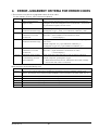
ERROR JUDGEMENT CRITERIA FOR ERROR CODES......................................................47
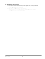
COUNTERMEASURES AGAINST TROUBLE.......................................................................48
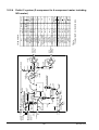
ADJUSTMENT IN HEAT TREATMENT FURNACE.............................................................50
MEASURING PRINCIPLE DIAGRAM....................................................................................52
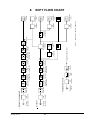
SOFT FLOW CHART ................................................................................................................53
INTERNAL WIRING DIAGRAM.............................................................................................54
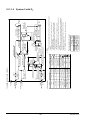
9.1
Analyzer unit.....................................................................................................................................54
9.1.1 Analyzer unit (ZSVF) ..............................................................................................................54
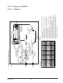
9.1.2 Analyzer unit (ZSVS) ..............................................................................................................55
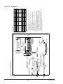
9.2 Sampling unit ....................................................................................................................................56
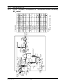
10. INTERNAL PIPING .................................................................................................................57
10.1 Analyzer unit...................................................................................................................................57
10.1.1 Analyzer unit (ZSVF) ............................................................................................................57
10.1.1.1 System 1........................................................................................................................57
10.1.1.2 System 2........................................................................................................................58
10.1.1.3 System 1 with O2 ..........................................................................................................59
10.1.1.4 System 2 with O2 ..........................................................................................................60
10.1.2 Analyzer unit (ZSVS) ............................................................................................................61
10.1.2.1 System 1........................................................................................................................61
10.1.2.2 System 2........................................................................................................................62
10.2 Sampling unit ..................................................................................................................................63
10.2.1 Outlet 1 system (1-component or 2-component meter excluding NOX meter) ......................63
10.2.2 Outlet 2 system (2-component to 4-component meter excluding NOX meter) ......................64
10.2.3 Outlet 1 system (1-component or 2-component meter including NOX meter).......................65
10.2.4 Outlet 2 system (2-component to 4-component meter including NOX meter) .......................66
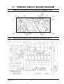
11.
PRINTED CIRCUIT BOARD DIAGRAM..............................................................................67
11.1
11.2
11.3
Amplifier printed circuit board at analyzer unit ..............................................................................67
Control printed circuit board at analyzer unit..................................................................................67
Main printed circuit board at analyzer unit .....................................................................................68
INZ-TN514401-E
iii
CAUTION ON SAFETY
First of all, read this “Caution on safety” carefully, and then use the gas analyzer in the correct way.
The cautionary descriptions listed here contain important information about safety, so they should always be
observed. Those safety precautions are ranked in 2 levels, “DANGER” and “CAUTION.”
DANGER
CAUTION
Wrong handling may cause a dangerous situation, in which there is a risk of
death or heavy injury.
Wrong handling may invite a dangerous situation, in which there is a
possibility of medium-level trouble or slight injury or only physical damage
is predictable.
Caution on installation and transport of gas analyzer
DANGER
• This unit is not explosion-proof type. Do not use it in a place with
explosive gases to prevent explosion, fire or other serious accidents.
CAUTION
• Install the gas analyzer in a place that satisfies the conditions described in
the “Instruction Manual.” Otherwise electric shock, fire, or malfunction
may result.
• During maintenance and check, care should be taken to keep the unit free
from cable chips or other foreign objects. Otherwise, it may cause fire,
trouble or malfunction of the unit.
• For lifting the gas analyzer, be sure to wear protective gloves. Bare
hands may invite an injury.
• The gas analyzer is heavy. Two or more persons should carry the gas
analyzer with sufficient care to avoid injury or damage to body.
iv
INZ-TN514401-E
Caution on piping
DANGER
In piping, the following precautions should be observed. Wrong piping
may cause gas leakage.
If the leaking gas contains a toxic component, there is a risk of serious
accident being induced.
Also, if combustible gas is contained, there is a danger of explosion, fire
or the like occurring.
• Connect pipes correctly referring to the instruction manual.
• Exhaust should be led outdoors so that it will not remain indoors.
• Exhaust from the gas analyzer should be relieved in the atmospheric air
in order that an unnecessary pressure will not be applied to the gas
analyzer. Otherwise, any pipe in the gas analyzer may be disconnected
to cause gas leakage.
• For piping, use a pipe and a pressure reducing valve to which oil and
grease are not adhering. If such a material is adhering, a fire or the like
accident may be caused.
Caution on wiring
CAUTION
• Be sure to perform specified grounding work to avoid electric shock or
malfunction.
• Be sure to use a power supply of correct rating. Connection of power
supply of incorrect rating may cause fire.
• Wiring work must be performed with the main power set to OFF to
prevent electric shocks.
• Wires should be the proper one meeting the ratings of this instrument. If
using a wire which cannot endure the ratings, a fire may occur.
Caution on use
DANGER
• For correct handling of calibration gas or other reference gases, carefully
read their instruction manuals beforehand.
CAUTION
• Do not operate the gas analyzer continuously with the cover opened.
Otherwise dust may enter, causing a failure.
• Do not open the cover and touch inside while the gas analyzer is
operated. Otherwise burns or electric shock may result.
INZ-TN514401-E
v
Caution on maintenance and check
DANGER
• Before performing work with the cover opened, be sure to turn off the
power and purge fully not only the gas analyzer but also measurement
gas lines with air and N2 gas. Be careful not to stain the filter and
packing with oil or grease. Otherwise gas leak may occur, thus causing
poisoning, fire, or explosion.
CAUTION
• Be sure to remove metallic objects such as a wristwatch or a ring.
Never perform work with wet hands to avoid electric shock.
• If the fuse is blown, eliminate the cause, and then replace it with the one
of the same capacity and type as before. Otherwise, shock hazard or
fault may be caused.
Others
CAUTION
• If the cause of any fault cannot be determined despite reference to the
instruction manual, be sure to contact your dealer or Fuji Electric’s
technician in charge of adjustment. If the instrument is disassembled
carelessly, you may have a shock hazard or injury.
• Do not use replacement parts not specified by the manufacturer.
Otherwise sufficient performance of the gas analyzer may not be
obtained, or accidents or failure may result.
• Dispose the parts removed for maintenance as noncombustible waste.
vi
INZ-TN514401-E
1. NAME OF MAIN DEVICES AND SERVICE PARTS
1.1
Analyzer unit
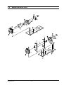
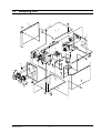
1.1.1
Analyzer unit (ZSVF)
2
4
7
8
1
5
7
6
10
9
11
3
No.
Parts order No.
1 ZZPZSV1-A030
Parts name
Cover assembly
2
ZZPZSV1-A020
Front panel assembly
3
ZZPZSV1-A010
Base assembly
4
ZZPZSV1-A280
Display unit
5
ZZPZSV1-A270
Membrane switch
6
ZZPZSV1-A250
Power supply
7
ZZPZSV1-A290
Amplifier printed board
8
ZZPZSV1-A300
Control printed board
9
ZZPZSV1-A310
Main printed board
10
ZZPZSV1-B070
Filter
11
ZZPZSV1-A200
Power switch
Recommended replacement cycle
Note
—
Handle not included
Window/flow checker not
—
included
—
Part not included
About 5 years
See Page 7 for replacement
(continuous operation)
procedure.
See Page 8 for replacement
500,000 times/1 contact
procedure.
See Page 9 for replacement
—
procedure.
See Page 10 for replacement
—
procedure.
See Page 11 for replacement
—
procedure.
See Page 13 for replacement
—
procedure.
When drain inflow or
See Instruction Manual for
contamination occurs
replacement procedure.
Contact: 10,000 times (ON/OFF)
See Page 14 for replacement
Lamp: About 2 years (continuous procedure.
operation)
Note 1: Specify “Parts order No.” on the list when ordering the parts.
Note 2: The replacement cycle varies depending on use conditions.
INZ-TN514401-E
1
1.1.2
Analyzer unit (ZSVS)
14
2
4
5
12
8
7
13
6
10
1
9
11
3
No.
Parts order No.
1 ZZPZSV1-A030
Parts name
Cover assembly
2
ZZPZSV1-A020
Front panel assembly
3
ZZPZSV1-A010
Base assembly
4
ZZPZSV1-A280
Display unit
5
ZZPZSV1-A270
Membrane switch
6
ZZPZSV1-A250
Power supply
7
ZZPZSV1-A290
Amplifier printed board
8
ZZPZSV1-A300
Control printed board
9
ZZPZSV1-A310
Main printed board
10
ZZPZSV1-B070
Filter
11
ZZPZSV1-A200
Power switch
12
ZZPZSV1-A750
Membrane filter
13
ZZPZSV1-A720
Pump
14
ZZPZSV1-A200
Fan
Recommended replacement cycle
Note
—
Handle not included
Window/flow checker not
—
included
—
Part not included
About 5 years
See Page 7 for replacement
(continuous operation)
procedure.
See Page 8 for replacement
500,000 times/1 contact
procedure.
See Page 9 for replacement
—
procedure.
See Page 10 for replacement
—
procedure.
See Page 11 for replacement
—
procedure.
See Page 13 for replacement
—
procedure.
When drain inflow or
See Instruction Manual for
contamination occurs
replacement procedure.
Contact: 10,000 times (ON/OFF)
See Page 14 for replacement
Lamp: About 2 years (continuous procedure.
operation)
Filter paper: About 1 to 2 months See Instruction Manual for
replacement procedure.
See Instruction Manual for
Diaphragm: About 1 year
replacement procedure.
Contact us for replacement
40,000 hours
procedure.
Note 3: Specify “Parts order No.” on the list when ordering the parts. The replacement cycle varies depending on
use conditions.
2
INZ-TN514401-E
1.2
Measurement unit
6
5
3
2
1
4
5
2
1
INZ-TN514401-E
3
6
No. Parts order No.
1 ZZPZSV1-E040
Parts name
Optical system baseboard
Recommended replacement cycle
—
2
ZZPZSV1-E050
Light source unit
About 7 years Note 3
3
ZZPZSV1-E070
Block cell
—
O-ring: About 2 years
4
ZZPZSV1-E270
Pipe cell
—
O-ring: About 2 years
5
ZZPZSV1-E280
Gas filter
About 7 years Note 3
6
ZZPZSV1-E200
Detector
About 7 years Note 3
Note
Motor/chopper included
See Page 15 for
replacement procedure.
Window/O-ring included
See Page 17 for
replacement procedure.
Window/O-ring included
See Page 17 for
replacement procedure.
See Page 20 for
replacement procedure.
Order No. varies depending
on range/component.
See Page 18 for
replacement procedure.
Note 1: Specify “Parts order No.” on the list when ordering the parts.
Note 2: The replacement cycle varies depending on use conditions.
Note 3: Gas is sealed in the light source unit/gas filter/detector.
Be sure to replace them following the recommended replacement cycle irrespective of the use
frequency.
7
Galvanic
About 2 years
Magnetic
About 7 years
Oxygen sensor
4
See Instruction Manual for
replacement procedure.
See Page 21 for
replacement procedure.
INZ-TN514401-E
1.3
Sampling unit
6
1
4
8
10
13
12
7
9
2
5
14
11
11
3
INZ-TN514401-E
5
No.
1
2
3
4
Parts order No.
ZZPZSV1-C040
ZZPZSV1-C020
ZZPZSV1-C010
ZZPZSV1-C030
Parts name
Top board assembly
Front panel
Base
Rear board assembly
Side board assembly
(right)
Side board assembly
(left)
5
ZZPZSV1-C050
6
ZZPZSV1-C060
7
ZZPZSV1-C250
Power supply
8
ZZPZSV1-C260
Exhaust fan unit
9
ZZPZSV1-C280
Mist filter
10
ZZPZSV1-C310
NO2/NO converter
11
ZZPZSV1-C320
Membrane filter
12
ZZPZSV1-C360
Electronic dehumidifier
13
ZZPZSV1-C370
Pump
14
ZZPZSV1-C200
Power switch
Recommended replacement cycle
—
—
—
—
—
Note
Handle not included
Parts not included
Parts not included
Parts not included
Window plate not included
—
See Page 22 for replacement
cycle.
About 3 years
See Page 22 for replacement
(continuous operation)
cycle.
See Instruction Manual for
Element: About 1 year
replacement procedure.
See Instruction Manual for
Catalyst: About 6 months
replacement procedure.
See Instruction Manual for
Filter paper: About 1 to 2 months
replacement procedure.
See Page 23 for replacement
Cooling fan: About 2 years
procedure.
See Instruction Manual for
Diaphragm: About 1 year
replacement procedure.
Contact: 5000 times (ON/OFF)
See Page 14 for replacement
Lamp: About 2 years
procedure
(continuous operation)
(analyzer unit, power switch)
—
Note 1: Specify “Parts order No.” on the list when ordering the parts.
Note 2: The replacement cycle varies depending on use conditions.
6
INZ-TN514401-E
2.
2.1
2.1.1
MAINTENANCE, INSPECTION, AND ADJUSTMENT AFTER REPAIR AND REPLACEMENT
Analyzer unit
Display unit
Recommended period of replacement: 5 years
Error mode
: End of service life of backlight, Deterioration of LCD
Phenomena
: Image is not displayed. Image is not clear or blinks.
Check
: (1) Press any key and check that the backlight comes on.
(2) Set <Parameter mode> and <Display OFF time setting> to OFF.
(3) Check the connection of the power supply connector of the backlight (main
printed circuit board CN6).
Also check the power supply voltage. (See “2.1.6 Main printed circuit board”
of this manual.)
(4) Check the connection of the connector of the LCD unit (Main printed circuit
board CN2).
Measures
: (1) Remove and then insert the connector to restore the performance of the contactor.
(2) Replace the display unit.
Replacement
: Remove the cable connected to the main printed circuit board off the connectors (CN6
and CN2).
Remove the fastening screw (4-M4 screw) and replace the display unit with a new
one.
Display unit
Cover assembly
Fastening screw
Main printed circuit board
Cable (CN6)
Cable (CN2)
Caution on replacement
(1) Be sure to turn off the power before removing and inserting the connector to
avoid damage to the display drive IC, etc.
7
TN512986-E
2.1.2
Membrane switch
Recommended period of replacement: 500,000 operations/contact
Error mode
: Wear of key contact
Phenomena
: Key operation cannot be performed.
Check
: Check that the cable of the membrane switch is securely connected to the connector
(main printed circuit board CN4).
Measures
Replacement
: (1) Remove and then insert the connector to restore the performance of the contactor.
(2) Replace the membrane switch.
: Remove the cable connected to the main printed circuit board off the connector (CN4).
The membrane switch is fastened to the front panel with two-sided tape. Peel off
the sheet and attach a new membrane switch.
(1)
(2)
(3)
(4)
Caution on replacement
Be sure to turn off the power before removing the connector to avoid damage
to the IC, etc.
Wipe the adhesive paste off the surface completely before attaching a new
switch to avoid peeling due to dust.
Connect the cable through the square hole on the front panel.
The connector of the main printed circuit board (CN4) is provided with a
stopper.
Slide the both sides of the switch slightly toward you. Do not pull it
forcibly to avoid damage.
Insert the cable securely and fasten it with the stopper to mount the switch.
8
INZ-TN514401-E
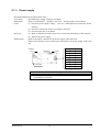
2.1.3
Power supply
Recommended period of replacement: None
Error mode
: Specified power supply voltage is not output.
Phenomena
: Image is not displayed. Display is not clear. Analog output is not produced.
Check
: (1) Check the power supply voltage. (See “2.1.6 Main printed circuit board” of this
manual.)
(2) Check the connection of the power supply connector.
(3) Check that the fuse is not blown.
Measures
: (1) Remove and then insert the connector to restore the performance of the contactor.
(2) Replace the power supply.
Replacement
: Remove the cables connected to the power supply (CN1 and CN2).
Remove the fastening screw (4-M3 screw) and replace the power supply with a new
one.
LDC60F-2
Nameplate
Front
4-M3 screw
Rear
Pin
Symbol
Voltage
1
V3
-15V
2
G2
GND2
3
G2
GND2
4
V2
+15V
5
G1
GND1
6
G1
GND1
7
V1
+5V
8
V1
+5V
Caution on replacement
(1) Be sure to turn off the power before removing and inserting the connector to
avoid damage to the parts.
INZ-TN514401-E
9
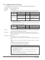
2.1.4
Amplifier printed circuit board
(The amplifier printed circuit boards 1 and 2 are the same parts with different gains.)
Recommended period of replacement: None
Error mode
: Failure of electronic parts
Phenomena
: Indication failure
Check
: (1) Check and adjust the voltage according to the description of the following table.
Item
Check terminal
Power supply
voltage
Between P15 and GND
Between N15 and GND
Knob for
adjustment
―
―
Between DV1 and SG1
VR2
Between DV2 and SG2
VR4
Detector voltage
Regulation voltage
+ 15.000 V DC ± 0.5 V DC
- 15.000 V DC ± 0.5 V DC
Voltage reading of the
detector for the 1st or the
3rd component ± 0.1V
Voltage reading of the
detector for the 2nd or the
4th component ± 0.1 V
(2) Adjust detector signals.
Feed zero gas and adjust the signals. If 2 printed circuit boards are provided,
make adjustment for each one of them.
Item
Check terminal
Detector signal
Between TP2 and SG1
Between TP6 and SG2
Knob for
adjustment
VR1
VR3
Regulation voltage
+ 2.000 V DC ± 0.1 V DC
+ 2.000 V DC ± 0.1 V DC
Measures
: (1) Remove and then insert the connector to restore the performance of the contactor.
(2) Replace the amplifier printed circuit board.
Replacement
: Remove the cables connected to the printed circuit boards (CN1, CN2, and CN3).
Remove the fastening screw (4-M3 screw) and replace the amplifier printed circuit
board with a new one.
Adjustment after replacement:
Insert connector CN3 only. (Do not insert CN1 or CN2.)
Insert the jumper pins (JP1 and JP2) into the same position as the old printed circuit
board.
Turn on the power and check and adjust “power supply voltage” and “detector
voltage.”
Turn off the power and insert connectors CN1 and CN2.
Turn on the power again, and adjust “detector signals.”
Perform zero and span calibrations to complete the work.
(1)
(2)
(3)
(4)
Caution on replacement
Be sure to turn off the power before removing and inserting the connector to
avoid damage to the detector.
Be careful not to cause short circuit with other parts while checking and
adjusting the voltage.
One or two amplifier printed boards will be supplied depending on the
number of components to be measured.
Be sure to warm up the instrument fully before adjusting detector signals.
10
INZ-TN514401-E
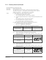
2.1.5
Control printed circuit board
Recommended period of replacement: None
Error mode
: Failure of electronic parts
Phenomena
: The sampling device is not operated. (End of service life of relay contact)
The pump is not operated. The brightness of the backlight cannot be adjusted.
Output is not produced. The chopping motor is not actuated.
Check
: (1) When output error is large or output is not produced
1) Check that proper output type is selected.
(See “Selecting output type” of the instruction manual.)
2) Adjust the output and check that it is changed and that fine adjustment can be
made.
(See “Adjusting output” of the instruction manual.)
3) Check that jumper pins are properly connected.
(See “Selecting output” of the instruction manual.)
(2) When brightness cannot be adjusted or backlight does not come on
1) Check that the display unit is operated properly.
(See “2.1.1 Display unit” of this manual.)
2) Check the brightness and voltage of the main printed circuit board.
Item
Check terminal
Regulation voltage
Brightness adjustment
voltage value
Main printed circuit board
Between TP9 and GND
29 V DC to 23 V DC
Can be adjusted evenly with
the brightness adjusting key.
When sample pump or drain pump is not operated (ZSVF)
Check the waveform of control output connector (CN13) with a selfsynchronous device.
Check terminal
Sample pump
Set the MEAS. key to ON and
check in measurement mode.
Control output
connector
Between 1 and 2
Control output
connector
Between 3 and 4
Drain pump
(Check in drain mode.)
(3-2)
INZ-TN514401-E
Output waveform
20 msec
About 30 V
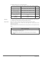
Item
When sample pump is not operated (ZSVS)
Check the waveform of control output connector (CN13) with a selfsynchronous device.
Item
Check terminal
Sample pump
Set
the
MEAS.
key to ON and
check in measurement mode.
Control output
connector
Between 1 and 2
11
Output waveform
20 msec
About 30 V
(3-1)
(4) When solenoid valve is not operated (ZSVF)
Check the continuity of the control output connector (CN13) with an ohmmeter.
Item
Check terminal
SV1, SV6
(Sample/zero switching)
SV2
(Drain pot for MSF)
SV3
(Drain pot for dehumidifier)
SV4
(Pot for zero gas)
SV5
(Span gas)
Measures
Replacement
Control output connector, Between 5 and 6
Control output connector, Between 7 and 8
Control output connector, Between 9 and 10
Control output connector, Between 11
and 12
Control output connector, Between 13
and 14
Result
Contact
ON/OFF
Contact
ON/OFF
Contact
ON/OFF
Contact
ON/OFF
Contact
ON/OFF
: (1) Remove and then insert the connector to restore the performance of the contactor.
(2) Replace the control printed circuit board with a new one.
: Remove the cables connected to the printed circuit boards (CN1 to CN13).
Remove the fastening screw (5-M3 screw), and replace the control printed circuit
board with a new one.
Insert the jumper pins (JP1 and JP2) into the same positions as the old printed circuit
board.
Caution on replacement
1) Be sure to turn of the power before removing and inserting the connector to
avoid damage to electronic parts.
2) Be careful not to cause short circuit with other parts while checking the
voltage.
12
INZ-TN514401-E
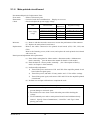
2.1.6
Main printed circuit board
Recommended period of replacement: None
Error mode
: Failure of electronic parts
Phenomena
: Control of each device malfunctions. Display error occurs.
Check
: Check and adjust the power supply voltage.
Item
Power supply
voltage
Check terminal
Knob for
adjustment
Regulation voltage
Between P15 and VG
―
+ 15.000 V DC ± 0.5 V DC
Between N15 and VG
Between Vcc and GND
Between VD and VG
Between N12 and VG
―
―
―
―
- 15.000 V DC ± 0.5 V DC
+ 5.000 V DC ± 0.5 V DC
+ 5.000 V DC ± 0.5 V DC
- 12.000 V DC ± 0.5 V DC
Measures
: (1) Remove and then insert the connector to restore the performance of the contactor.
(2) Replace the main printed circuit board.
Replacement
: Remove the cables connected to the printed circuit boards (CN2, CN3, CN4, and
CN6).
Remove the fastening screw (6-M3 screw) and replace the main printed circuit board
with a new one.
Data input and adjustment after replacement:
(1) Enter all the setting data for <Menu mode>/<Parameter mode>/<Maintenance
mode> manually. (See the instruction manual for details of each mode.)
(2) Enter the data for <Factory mode> manually. (See <Description of factory
mode> in Chapter 3 of this manual.)
(3) Perform offset adjustment.
1) Turn off the power and remove CN1 and CN2 of the amplifier printed circuit
board (detector signal open).
2) Turn on the power, and make <Factory mode> and <5. Zero offset> settings.
3) Turn off the power again, and connect CN1 and CN2 on the amplifier printed
circuit board.
(4) Perform zero and span calibrations to complete the work.
Caution on replacement
1) Be sure to turn off the power before removing and inserting the connector to
prevent damage to electronic parts.
2) Be careful not to cause short circuit with other parts while checking the
voltage.
3) We recommend you to order a main printed circuit board with data already
entered. Specify “Date of manufacture,” “Serial No.” and “Type” when
placing your order.
INZ-TN514401-E
13
2.1.7
Power switch
Recommended period of replacement:
Contact; 10,000 times (ON/OFF), Lamp; About 2 years
Error mode
: Contact deterioration. End of service life of lamp
Phenomena
: The power is not turned on. (The display does not come on.)
The power can be turned on but the lamp does not come on.
Check
: Check the fuse for blowing.
Measures
: Replace the power switch.
Replacement
: Remove the power switch, while pressing the projection for fastening from within the
front panel. Remove the four cables from the tab terminal.
12
Tab terminal
11
25
24
12
11
25
24
Circuit
Projection for fastening
Caution on replacement
(1) Be sure to remove the power cable before inserting/removing the connector
to avoid electric shock.
(2) Be sure to connect wiring securely, referring to the wiring diagram.
14
INZ-TN514401-E
2.2
Measuring unit
2.2.1
Light source unit
Recommended period of replacement: Seven years
Error mode
: (1) Motor rotation stop
(2) Short circuit and disconnection of the light source electrically heated wire.
(3) Sealed gas leakage in light source
Phenomena
: Unstable reading, scale out, and occurrence of Error-1
Check
: (1) Motor:
• Turn on the power and visually check that the shaft rotates.
(Remove the light source unit, and you can check the rotation of the chopper
through the window.)
• Check that abnormal sound is not emitted.
(2) Light source unit
• Remove the power supply cable of the light source unit, and check that the
resistance value falls within the 37Ω ± 2Ω range.
There is a break if the reading appears infinite.
With the decrease of the resistance value, the reading drifts in the minus direction.
(3) If the reading becomes unstable because of the gas in the atmosphere, sealed gas
may be leaking.
<Motor unit for light source>
Light source motor unit
as viewed from cell side
Motor shaft
Check sector rotation
from here.
1) Checking chopper rotation
Measures
Replacement
INZ-TN514401-E
Measure the resistance
between terminals
with cables disconnected.
2) Measuring resistance value
of light source
: Replace the light source unit.
: Remove the screw fastening the unit to the optical system baseboard (2-M4), and
replace the unit with a new one.
15
Adjustment after replacement:
Adjust the signals from the detector on the amplifier printed circuit board.
(1) Feed zero gas.
Adjust the replaced optical system (amplifier printed circuit board) only.
Item
Check terminal
Knob for
adjustment
Regulation voltage
Detector signal
Between TP2 and SG1
Between TP6 and SG2
VR1
VR3
+ 2.000 V DC ± 0.1 V DC
+ 2.000 V DC ± 0.1 V DC
(2) Perform zero and span calibrations to complete the work.
Caution on adjustment
▪ Be sure to warm up the instrument fully before adjusting detector signals.
16
INZ-TN514401-E
2.2.2
Cell, cell window and O-ring (common to block cell and pipe cell)
Service life
: Usable unless contaminated or corroded.
Recommended period of replacement: 2 years with O-ring
(1) Error mode : Contamination of cell, mixture of foreign matter, and contamination of cell window
Phenomena : Scale-out indication, drift and calibration error occurred to gas analyzer
Check
: Disassemble the cell to assure that the inside is clean.
(2) Error mode : Crack in cell window
Phenomena : No change in indication, slow response, calibration error, and indication fluctuation
Check
: Visually check the cell window for damage.
Measures
: Cell
Clean the inside of the cell (refer to the instruction manual for
details).
Replace if the inside is exposed to excessive
contamination or corrosion.
Cell window
Clean the cell window. Replace if the inside is exposed to
excessive contamination.
Replacement
: See the instruction manual.
Adjustment after clean and replacement:
Adjust detector signals.
(1) Feed zero gas and make an adjustment.
Item
Check terminal
Knob for
adjustment
Regulation voltage
Detector signal
Between TP2 and SG1
Between TP6 and SG2
VR1
VR3
+2.000 V DC ± 0.1 V DC
+2.000 V DC ± 0.1 V DC
(2) Perform zero and span calibrations to complete the work.
Caution on adjustment
▪ Be sure to warm up the instrument fully before adjusting detector signals.
INZ-TN514401-E
17
2.2.3
Detector (other than O2 sensor)
Recommended period of replacement: 7 years
(1) Error mode : Damage to mass-flow detector
Phenomena : Scale-out indication of the gas analyzer
Check
: Turn OFF the power of the gas analyzer and disconnect
the connector connected from the detector to amplifier
printed circuit board. (Amplifier printed circuit board
CN1, CN2). Measure resistance between 4 – 7 and 5 –
7 of the bridge printed circuit board on the detector.
The measure values must be between 25Ω and 60Ω. If
the resistance value is fluctuated beyond the specified
range, the detector element may be damaged.
Note: Do not use measurement instrument that
allows a current of 2 mA or more to be
supplied when measuring resistance,
otherwise the element can be damaged.
Detector
Bridge Pt board
Brawn,Red,White,Red
(2) Error mode : Sensitivity deterioration due to sealed gas leak
Phenomena : Calibration error and fluctuation in indication
Check
: Check indication value at zero point
......... Check the indication value for each component on the <Sensor Input Value>
screen in the <Maintenance mode>.
If the light source is in normal condition and the cell is free of contamination, the
counter value indicates 38000 to 42000 when zero gas is supplied. If the counter
value is below the range, sensitivity can be degraded.
Measures
: Replace detector.
Replacement
: (1) Block cell
Remove the light source unit.
The detector is fastened together with the light source unit and the block cell.
Remove the screw at the bottom of the detector (2-M4), and the light source unit
can be separated. Then remove the screw at the top of the block cell (2-M4) and
remove the detector.
(2) Pipe cell
Remove the optical system baseboard from the main unit.
The detector is fastened with a screw (2-M4) at the back of the optical system
baseboard.
18
INZ-TN514401-E
Adjustment after replacement:
Adjust the amplifier printed circuit board.
(1) Adjusting the power supply voltage of the detector:
Insert connector CN3 only. (Do not insert CN1 and CN2.)
Turn on the power and adjust the “detector voltage” shown below.
Item
Check terminal
Knob for
adjustment
Between DV1
and SG1
VR2
Between DV2
and SG2
VR4
Detector voltage
Regulation voltage
Voltage reading of the detector
for the 1st or the 3rd component
± 0.1 V
Voltage reading of the detector
for the 2nd or the 4th component ± 0.1 V
(2) Adjusting detector signals:
Feed zero gas.
Turn off the power and insert connectors CN1 and CN2.
Turn on the power again, and adjust the “detector signals.”
Adjust the replaced optical system (amplifier printed circuit board) only.
Item
Detector signal
Check terminal
Knob for
adjustment
Regulation voltage
Between TP2
and SG1
VR1
+2.000 V DC ± 0.1 V DC
Between TP6
and SG2
VR3
+2.000 V DC ± 0.1 V DC
(3) Perform zero and span calibrations to complete the work.
Note: Adjust the detector voltage on the
printed circuit board and plug the
connector into the detector. Do not
insert the connector before voltage
regulation, or the element may be
damaged.
Detector voltage reading
Type of detector
Detector voltage
Caution on adjustment
▪ Be sure to warm up the instrument fully before adjusting detector signals.
INZ-TN514401-E
19
2.2.4
Gas filter
Recommended period of replacement: 7 years
Error mode
: Sealed gas leak
Phenomena
: Increase of interference of other gases, linear deficiency, and drifting of reading in
minus direction
Check
: Perform zero/span calibration, feed the gas at the rate around the center of the range,
and check the linearity.
Measures
: Replace the gas filter.
Replacement
: Replace by referring to “2.2.3 Detector (other than O2 sensor)” of this manual.
Adjustment after replacement:
Adjust the detector signals of the amplifier printed circuit board.
(1) Feed zero gas.
Turn on the power and adjust “detector signals.”
Item
Check terminal
Knob for
adjustment
Regulation voltage
Detector
signal
Between TP2 and SG1
Between TP6 and SG2
VR1
VR3
+2.000 V DC ± 0.1 V DC
+2.000 V DC ± 0.1 V DC
(2) Perform zero and span calibrations to complete the work.
Caution on adjustment
▪ Be sure to warm up the instrument fully before adjusting detector signals.
20
INZ-TN514401-E
2.2.5
Oxygen sensor
(1) Galvanic oxygen sensor
Recommended period of replacement: 2 years
Error mode
: Deterioration of the sensor
Phenomena
: Span drift or unstable reading due to deterioration of sensitivity
Check
: Remove the connector (CN9) inserted into the printed circuit board for control.
Connect a digital voltmeter to both sides of the connector on the oxygen sensor side.
If the voltage is 10mV or lower in atmospheric suction state, replace the sensor.
Measures
: Replace the galvanic oxygen sensor.
Replacement
: See the instruction manual.
Adjustment after replacement:
Perform zero/span calibration of the oxygen sensor to complete the work.
(2) Magnetic sensor
Recommended period of replacement: 7 years
Error mode
: Deterioration of the sensor
Phenomena
: Drift or unstable reading due to deterioration of sensitivity
Check
: Check the voltage between check terminals TP4 and SC on the main printed circuit
board.
Main printed circuit board
check terminal
Voltage when zero gas
is fed
Voltage when span gas
(21%O2) is fed
Between TP4 and SC
0.000 V ±0.1 V
Normal range:
0.500 V or higher
Measures
Replacement
: Replace the magnetic oxygen sensor.
: Remove the flat connector inserted into the oxygen sensor.
Remove the screw on the oxygen sensor mounting stage (2-M4).
Replace the oxygen sensor with a new one.
Adjustment after replacement:
Perform zero/span calibration of the oxygen sensor to complete the work.
INZ-TN514401-E
21
2.3
2.3.1
Sampling unit
Power supply
Recommended period of replacement: None
Error mode
: Specified power supply voltage is not output.
Phenomena
: Solenoid valve, fan, or thermoregulator does not operate.
Check
: (1) Check the power supply voltage.
Remove the connector (CN2) of the power supply, and check that the voltage
between 8 and 1 (GND) falls within the 12.000 V DC ± 0.5 V DC range.
: (2) Check the connection of the power supply connector.
: (3) Check that the fuse is not blown.
Measures
: (1) Remove and then insert the connector to restore the performance of the contactor.
(2) Replace the power supply.
Replacement
: Remove the cables connected to the power supply (CN1 and CN2).
Remove the fastening screw (4-M3 screw) and replace the power supply with a new
one.
4-M3 screw
Output (+)
Output (-)
Pin
Symbol
Voltage
-V
GND
+V
+12V
1
CN2
RC (-)
Top
2
3
4
5
6
CN1
FG
Input (N)
Input (L)
7
8
Bottom
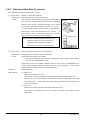
2.3.2
Exhaust fan unit
Recommended period of replacement: 3 years
Error mode
: End of service life of the fan
Phenomena
: The fan does not operate.
Check
: Check the power supply voltage.
Check that voltage of 12.000 V DC ± 0.5V DC is supplied between relay terminals 13
and 16 (GND).
Measures
: Replace the fan with a new one.
Replacement
: Remove the wiring connected between relay terminals 13 and 16 (GND).
Remove the nut fastening the fan unit at the rear face assembly (4-M4) and then
remove the unit.
22
INZ-TN514401-E
2.3.3
Electric dehumidifier
Recommended period of replacement: Cooling fan 2 years
Error mode
: End of service life of the fan
Phenomena
: The fan does not operate.
Check
: (1) Check that the reading of the thermoregulator mounted at the backboard falls
within the range from 1°C to 5°C.
(2) Check that the fan is rotating.
Measures
: Replace the electronic dehumidifier.
Replacement
: (1) Remove the piping.
1) Remove the gas inlet/outlet piping at the top (2 pipes).
2) Remove the drain outlet pipe at the bottom.
We recommend you to remove the piping from the bottom of the drain pot and
then separate it from the pot.
(2) Remove the wiring.
1) Remove the fan wiring from the relay connector.
2) Remove the thermocouple connected between 1 and 2 of the thermoregulator.
3) The power supply is connected to SSR terminal No.8 and the relay connector.
(3) The main unit is mounted to the baseboard assembly with a fastening screw (4M4).
Remove the screw, and replace the electronic dehumidifier with a new one.
Caution on replacement
(1) Be sure to use a hose band for piping connection at the time of assembly.
Otherwise insufficient airtightness may result.
(2) Be sure to discharge the drain before replacing the dehumidifier. Wipe off the
moisture on the drain to avoid short circuit.
(3) Replace the electronic dehumidifier together with the thermoregulator.
Air suction
SSR
Fan
Backboard
Thermoregulator
Mounting screw
4-M4
Thermocouple
(To thermoregulator)
Wiring for fan
(To relay connector)
Outlet pipe
Electronic
dehumidifier
Inlet pipe
Power supply cable
(To SSR (No. 8))
INZ-TN514401-E
23
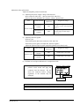
3.
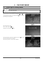
3.1
FACTORY MODE
How to go to Factory Mode
Caution
Factory adjustment is made in this mode.
Be careful not to enter wrong settings to avoid malfunction of the analyzer.
Point the cursor to “14. To Factory” by using the
on the Maintenance Mode screen and enter the
ENT
or
key.
key
Then, the
password input screen appears.
ENT
Enter the password, “2404.”
Select a digit using the
Change the value using the
key.
key.
ENT
After password entry has been completed, press the
ENT
key, and
the Factory Mode initial screen appears.
The cursor is placed at “1. PILC Code” as default.
24
INZ-TN514401-E
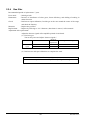
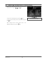
3.2
How to go to each item in Factory Mode
On the factory mode screen that appears, move the cursor to
the item to be set using the
,
, or
MODE
key.
ENT
To get access to each setting screen, press the
ENT
key.
To return from each setting screen to the initial screen, press
the
ESC
key.
When escaping from the Factory Mode screen to the
Maintenance Mode screen, press the
INZ-TN514401-E
ESC
key.
25
ESC
Into each parameter screen
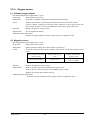
3.3
3.3.1
Setting item in Factory Mode
PILC code
Function: Set PILC code and device No.
The settings within each factory mode are not revised
automatically.
Factory mode initial screen
The cursor is in 1.
ENT
ESC
Operation: The PILC code setting screen is shown at right.
Change the value using the
Select a digit using the
and
MODE
keys.
key.
Press the
ENT
key to confirm the setting.
Press the
ESC
key to return to the factory mode initial screen.
Note that the data is not stored unless the
ENT
key is pressed.
ENT
Setting contents: 0 to 9, A to Z
ZSV00001000000000000]
Initial value: [PILC:
[Serial No.: 00000000]
Note 1: Do not enter hyphen for PILC.
26
Measurement mode initial screen
INZ-TN514401-E
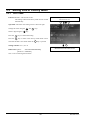
3.3.2
Language setting
Function: Switch the language for display between Japanese and
English.
Factory mode initial screen
The cursor is in 2.
ENT
ESC
Operation: The language select screen is shown at right.
Press the
ENT
key to highlight the setting.
ENT
Select Japanese or English using the
Press the
MODE
Press the
ESC
and
MODE
keys.
key to confirm the setting.
to cancel the setting.
Setting contents: Japanese, English
Initial value: [English]
Note: The display is switched between Japanese and English as
soon as the
INZ-TN514401-E
ENT
key is pressed.
27
ENT
or
ESC
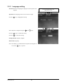
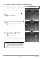
3.3.3
Number of channels (Measured component setting)
Function: Set the components for each channel to be displayed
on the measurement screen. The setting determines
the number of components to be measured.
Factory mode initial screen
The cursor is in 3.
ENT
ESC
ENT
ESC
ENT
ESC
Operation: The screen for setting the number of channels is
shown at right.
Move the cursor to infrared ray component using the
MODE
and
keys.
Press the
ENT
key to enter the mode.
Move the cursor to optical system to be selected using the
and
MODE
Press the
keys.
ENT
key to highlight the name of components selected.
Select a component name using the
Press the
ENT
key to confirm the setting.
Press the
ESC
key to cancel the setting.
and
MODE
keys.
Optical system 1 is displayed on the left side, and optical system
2 on the right side viewed from the front of the instrument.
Connector CN1 on the amplifier printed circuit board is for
optical system X-1, and CN2 is for optical system X-2.
Note: Make the setting sequentially beginning from optical
system 1-1. Be sure to select “None” for the optical
systems without the sensor. Do not select “None” for
all of them. Otherwise A/D conversion failure may
result.
28
INZ-TN514401-E
Then select presence/absence of O2 sensor and output type
except for “infrared ray sensor.”
Select other channel allocations using the
Press the
ENT
ENT
MODE
ESC
ENT
ESC
ENT
ESC
keys.
and
keys.
MODE
key to highlight the name of component selected.
Select a component to be set using the
Press the
ENT
key to confirm the setting.
Press the
ESC
key to cancel the setting.
and
MODE
keys.
Initial value:
ZSVF; [CH1 = NOX, CH2 = SO2, CH3 = CO,
CH4 = CO2, CH5 = O2, CH6 = Average corrected
NOX, CH7 = Average corrected SO2,
CH8 = Average corrected CO]
ZSVS; [CH1 = CH4, CH2 = CO2, CH3 = CO,
CH4 = CP calculation
Setting contents:
Instantaneous value:
NOX, NO, SO2, CO, CO2, CH4, HC, C3H8, O2
Instantaneous value after O2 correction:
NOx correction, SO2 correction, CO correction
Moving average after O2 correction:
Average after NOx correction, Average after SO2
correction, Average after CO correction
CP calculation value:
CP calculation
Others: None
Note: Channels and measured components are independent of each other.
Make the setting so that the sensor input corresponds to the display.
INZ-TN514401-E
ENT
key to enter the mode.
Select the channel to be set using the
Press the
and
Factory mode initial screen
The cursor is in 3.
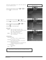
29
3.3.4
Channel parameter (setting of range and unit)
Function: Set the number of ranges, unit of concentration,
decimal point position of the range, and the range
value of each component.
Factory mode initial screen
The cursor is in 4.
ENT
ESC
ENT
ESC
Operation: The CH data setting screen is shown at right.
Select the channel to be set using the
Press the
ENT
ENT
MODE
keys.
key to enter the mode.
Select the item to be set using the
Press the
and
and
MODE
keys.
key to highlight the setting selected.
Select the setting using the
Move the digit using the
and
MODE
keys.
key and make the setting for each
digit.
Press the
ENT
key to confirm the setting.
Press the
ESC
key to cancel the setting.
Setting contents:
Number of ranges:
Number of measurement ranges; 1, 2, 3 (3 max.)
Unit:
Unit of measurement range; ppm or vol%, mg/m3
or g/m3 (Units ppm and vol% or mg/m3 and g/m3
cannot be selected at the same time. It is allowed
that ppm is selected for range 1, while vol% is
selected for range 2. Combination of ppm and
mg/m3 is not allowed.)
Decimal point position:
Decimal point position of measured concentration
Range setting: Range value setting
Setting up to the first decimal place (such as 0.5 vol%) is
allowed.
Note 1: The full scale of the linearization table setting should
be the maximum range of the setting range.
Setting example: In the case of the screen shown
above, the full scale of range 1 is 500.0 ppm, and
that of range 3 is 2000 ppm.
Note 2: The ratio of range of range 1 to range 3 is 1 to 5 at
the maximum.
30
INZ-TN514401-E
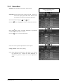
3.3.5
Zero offset
Function: Store the offset value of the A/D converter.
Factory mode initial screen
The cursor is in 5.
ENT
ESC
ENT
ESC
ENT
ESC
Operation: The zero offset screen is shown at right. Be sure to
remove the input signal cable of the detector from
the amplifier board before making the adjustment.
Select the channel using the
Press the
Press the
ENT
ENT
and
MODE
keys.
key to highlight the name of component selected.
key again, and offset adjustment is performed
automatically and the value is selected.
Press the
ESC
key to cancel the adjustment.
Select ALL CH to perform adjustment for all the inputs.
Setting contents: Initial value [20000]
Note: Offset adjustment performed in this mode is for infrared
ray component only. Perform O2 offset adjustment of
magnetic or galvanic O2 meter in “3.3.8 O2 adjustment”
mode.
INZ-TN514401-E
31
3.3.6
Linearizer
Function: Set the linearize table calculated using the calibration
curve measurement data.
This allows linearity correction to be made.
Factory mode initial screen
The cursor is in 6.
ENT
ESC
ENT
ESC
Operation: The linearize table setting screen is shown at right.
Select the CH to be set using the
Press the
ENT
and
MODE
keys.
key to enter the table setting screen.
Note: O2 meter can also be set.
Note that O2 meter setting is not required in ordinary cases
because the sensor output signals of magnetic and galvanic
O2 meters are linear.
Select the set point using the
Press the
ENT
,
and
MODE
keys.
key to highlight the setting.
ENT
Change the setting using the
Move the digit using the
and
MODE
ENT
or
ESC
keys.
key and make the setting for each
digit.
Press the
ENT
key to confirm the setting.
Press the
ESC
key to cancel the setting.
Setting contents: The linearization function uses 16 broken line
approximation for calculation.
Enter the
value of each break point calculated from the
calibration curve for setting.
X and Y represent the X and Y axes, and points 1 to 16
correspond to each break point.
The first break point and the 16th break point correspond to the
zero and values of the maximum range, “00000” and “20000”
respectively.
Initial value: In the order of correction points from 1 to16 both
for X and Y axes [0, 800, 1600, 2400, 3200, 4000,
5000, 6000, 7000, 8000, 10000, 12000, 14000,
16000, 18000, 20000] (Non-linear state)
32
INZ-TN514401-E
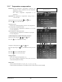
3.3.7
Temperature compensation
Function: Set the temperature compensation coefficient and
temperature counts calculated from the temperature
characteristic test data.
This allows temperature compensation to be
performed.
Operation: The temperature compensation setting screen is
shown at right.
Select the item to be set using the
Press the
ENT
and
MODE
Factory mode initial screen
The cursor is in 7.
ENT
ESC
ENT
ESC
keys.
key to enter the mode.
Temperature table:
Set the count of the temperature sensor for each temperature.
Zero temperature compensation table:
Set the temperature compensation coefficient at zero point
for each temperature.
Span temperature compensation table:
Set the temperature compensation coefficient at span point
for each temperature.
▪ When temperature compensation table is selected
Select the count using the
Press the
ENT
,
, and
MODE
keys.
key to highlight the setting.
ENT
Change the setting using the
Move the digit using the
and
MODE
keys.
key, and make the setting for each
digit.
Press the
ENT
key to confirm the setting.
Press the
ESC
key to cancel the setting.
Setting contents:
The X-axis represents temperature (°C).
The Y-axis represents temperature count (A/D conversion
value of the temperature sensor).
Initial value:
X-axis: In the order from 1 to 6 [-05, +05, +15, +25, +35, +45]
Y-axis: In the order from 1 to 6 [15940, 16750, 17560, 18370, 19145, 19920]
INZ-TN514401-E
33
ENT
or
ESC
▪ When zero temperature compensation table is selected
Select a channel to be set using the
Press the
ENT
and
keys.
MODE
key to enter the mode.
ENT
Select an item to be set using the
Press the
ENT
,
, and
MODE
ESC
keys.
key to highlight the setting.
ENT
Change the setting using the
Move the digit using the
and
MODE
ENT
or
ESC
keys.
key, and make the setting for each
digit.
Press the
ENT
key to confirm the setting.
Press the
ESC
key to cancel the setting.
Setting contents:
Enter temperature (°C) for X-axis according to the
temperature table (change not allowed).
Enter zero temperature compensation coefficient value for Yaxis.
Initial value: (The initial value of O2 meter differs only for Yaxis.)
X-axis: [-05, +05, +15, +25, +35, +45]
Y-axis: [1.0000] for all
Y-axis of O2 meter: [+00000] for all
34
INZ-TN514401-E
▪ When span temperature compensation table is selected
Select a channel to be set using the
Press the
ENT
and
keys.
MODE
key to enter the mode.
ENT
Select an item to be set using the
Press the
ENT
,
, and
MODE
keys.
key to highlight the setting.
ENT
Change the setting using the
Move the digit using the
and
MODE
keys.
key, and make the setting for each
digit.
Press the
ENT
key to confirm the setting.
Press the
ESC
to cancel the setting.
Setting contents:
Enter span temperature compensation coefficient.
Initial value: (The initial value of O2 meter differs only for Yaxis.)
X-axis: [-05, +05, +15, +25, +35, +45]
Y-axis: [1.0000] for all
INZ-TN514401-E
ESC
35
ENT
or
ESC
3.3.8
O2 adjustment
Function: Select magnetic or galvanic system, and make
required adjustments for each O2 meter.
Factory mode initial screen
The cursor is in 8.
ENT
ESC
ENT
ESC
Operation: The O2 adjustment setting screen is shown at right.
▪ O2 meter selection
Select the item to be set using the
Press the
ENT
and
MODE
keys.
to enter the mode.
Select the setting contents using the
Press the
ENT
key to confirm the setting.
Press the
ESC
key to cancel the setting.
and
MODE
keys.
Setting contents:
Initial value: [Galvanic (Full cell)]
O2 meter selection: Magnetic, Galvanic
Galvanic system only is used for ZSVS.
Note: Be sure to perform O2 offset adjustment.
36
INZ-TN514401-E
▪ O2 offset adjustment
In O2 offset adjustment, electric offset values required for the
measurement with magnetic and galvanic O2 meters are stored.
Operation: The O2 offset adjustment screen is shown at right.
Remove JP10 (jumper pin) on the control printed
circuit board and short-circuit the pin No.2 to the
GND pin of the main printed circuit board before
making the adjustment.
Select the item to be set using the
Press the
ENT
and
MODE
keys.
key to enter the mode.
ENT
Press the
ENT
ESC
key again, and “O2 offset adjustment underway”
appears in the comment field, and adjustment is completed
automatically.
ENT
INZ-TN514401-E
37
Auto
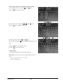
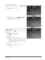
3.3.9
Output selection
Function: Select 4 to 20 mA DC or 0 to 1 V DC for analog
output value.
Factory mode initial screen
The cursor is in 9.
Note: Select the output and then switch the output
jumper pin on the control board.
ENT
ESC
Operation: The analog output selection screen is shown at right.
Select the output to be set (OUT 1 to 8) using the
and
MODE
keys.
Press the
ENT
key to highlight the setting.
ENT
Change the setting using the
and
MODE
Press the
ENT
key to confirm the setting.
Press the
ESC
key to cancel the setting.
ENT
or
ESC
keys.
Setting contents:
The outputs (OUT) 1 to 8 correspond to CH1 to CH8
respectively.
Initial value:
[4 to 20 mA] for all of OUT1 to OUT8
38
INZ-TN514401-E
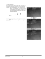
3.3.10
Output adjustment
Function: Adjust the zero point and span point of the analog
output to 4 to 20 mA or 0 to 1 V DC.
Factory mode initial screen
The cursor is in 10.
ENT
ESC
Operation: The Analog Output Adjustment screen is as shown
in right.
Select the output to be adjusted (OUT 1 to 8) using the
, and
MODE
,
keys, and connect the digital voltmeter to the
output terminal.
* See “3.3.9 Output selection” for the correspondence
between OUT No. and output.
Press the
ENT
key to highlight the setting.
Adjust the value using the
and
MODE
ENT
keys, seeing the
value on the digital voltmeter.
Move the digit using the
key, and make an adjustment for
each digit.
Adjust the output as follows:
Zero: 4 mA ± 0.05 mA DC or 0 V ± 0.005 V DC
Span: 20 mA ± 0.05 mA DC or 1 V ± 0.005 V DC
Press the
ENT
key to confirm the setting.
Press the
ESC
key to cancel the setting.
Setting contents:
The outputs (OUT) 1 to 8 correspond to CH1 to CH8
respectively.
The settings are digital values transmitted to the D/A
converter.
Initial value: OUT1 to 8
Current output: [Zero = 0800]
[Span = 3850]
Voltage output: [Zero = 0540]
[Span = 3440]
INZ-TN514401-E
39
ENT
or
ESC
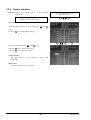
3.3.11
Interference compensation
Function: Correct the interference of other gases.
The compensation includes the following:
▪ NOX to H2O
▪ SO2 to H2O
▪ CO to CO2
Factory mode initial screen
The cursor is in 11.
ENT
ESC
Note: The compensation screen is not displayed unless target
components are selected in section 3.3.3 “Number of
channels (measurement component setting).”
Operation: The compensation setting screen is shown at right.
▪ How to correct NOX and SO2 to H2O
Select the component to be corrected using the
and
MODE
keys.
Press the
ENT
key to enter the mode.
ENT
ENT
or
ESC
Make +/- setting and enter the concentration value using the
and
MODE
keys.
Move the digit using the
key, and make the setting for each
digit.
Press the
ENT
to confirm the selection.
Press the
ESC
key to cancel the setting.
Setting contents:
(1) Select +/- of the effect of interference.
(2) Measure the value of effect of interference beforehand,
and enter the concentration value reflecting the effect.
(Enter the concentration value affected by the
interference.)
Initial value: [+0000 count] both for NOX and SO2
Note: The compensation value is increased/decreased in this
mode. Determine the compensation value in
Maintenance mode <6. Moisture interference
adjustment>.
40
INZ-TN514401-E
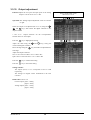
▪ How to correct CO to CO2
Select the component to be corrected using the
and
MODE
keys.
Press the
ENT
key to enter the mode.
ENT
Select the correction point using the
Press the
ENT
,
, and
MODE
keys.
key to highlight the setting.
ENT
Make +/- setting and enter the concentration value using the
and
MODE
keys.
Move the digit using the
key, and make the setting for
each digit.
Press the
ENT
to confirm the selection.
Press the
ESC
key to cancel the setting.
Setting contents:
(1) Select +/- of the effect of interference.
(2) Measure the value of effect of interference
beforehand, and enter the concentration value
reflecting the effect. (Enter the concentration value
affected by the interference.)
Initial value:
CO2: [0% 5% 10% 15% 20% 25%]
CO: [+00.00 ppm]
INZ-TN514401-E
ESC
41
ENT
or
ESC
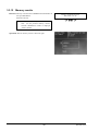
3.3.12
Memory rewrite
Function: Directly read and write EEPROM and RAM data to
the specified address.
Perform soft reset.
Factory mode initial screen
The cursor is in 12.
ENT
ESC
Note: An address map is required to write values
here. Do not perform memory rewrite,
because malfunction results if improper
value is written.
Operation: The set memory screen is shown at right.
42
INZ-TN514401-E
▪ Memory read/write
Move the cursor to the address to be written pressing the
ENT
key.
Enter the value using the
Move the digit using the
and
ENT
ESC
ENT
ESC
key.
MODE
key, and make the setting for
each digit.
Data is displayed as the value to be written by specified
address.
Press the
ENT
key, and the cursor moves to the value to be
written.
Enter the value using the
Move the digit using the
and
MODE
keys.
key and make the setting for
each digit.
Press the
ENT
key to confirm the setting.
Press the
ESC
key to cancel the setting.
▪ Soft reset
Move the cursor to “Reset” and then press the
ENT
key.
“Reset” is highlighted.
Press the
ENT
key again, and reset is carried out and the program is started from the beginning.
The measurement screen appears again.
Press the
ESC
INZ-TN514401-E
key to cancel the reset.
43
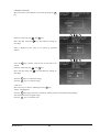
3.3.13
Coefficient confirmation
Function: Displays zero offset and calibration coefficient.
Factory mode initial screen
The cursor is in 13.
ENT
ESC
ENT
ESC
Operation: The initial coefficient confirmation screen is shown
at right.
Select the item to be set using the
Press the
ENT
and
MODE
keys.
key to enter each display screen.
▪ When offset is selected
Display contents:
Offset ......Offset value of infrared ray detector and that of O2
meter
Press the
ESC
key to return to the initial coefficient confirmation
screen.
▪ When calibration coefficient is selected
Display contents:
Display is made by range.
Zero.........Zero calibration coefficient
Span ........Span calibration coefficient
Press the
Press the
and
ESC
MODE
keys to scroll the CH display.
key to return to the initial coefficient
confirmation screen.
Note: You can check the coefficient but cannot change it in
this mode.
44
INZ-TN514401-E
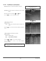
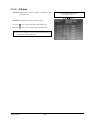
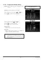
3.3.14
A/D data
Function: Measures the counter readings immediately after
A/D conversion.
Factory mode initial screen
The cursor is in 14.
ENT
Operation: The A/D data screen is shown at right.
Press the
MEAS
key to operate the pump and feed the gas.
Press the
ESC
key to return to the initial A/D data screen.
Note: You can check the count of input signals but cannot
change the value in this mode.
INZ-TN514401-E
45
ESC
3.3.15
Component display setting
Function: Used to measure the same components (2 optical
systems).
Factory mode initial screen
The cursor is in 15.
ENT
ESC
ENT
ESC
Operation: Component display is shown at right.
Select a component to be set using the
Press the
ENT
and
MODE
keys.
key, and the setting is highlighted.
Change the setting using the
and
MODE
keys.
Press the
ENT
key to confirm the setting.
Press the
ESC
key not to confirm the setting.
Setting contents:
NO, NOX, SO2, CO2, CO, HC, C3H8, CH4, None
Initial value:
Same as those given in section “3.3.3 Number of
channels (Measured component setting)”
Note: The component display set in section 3.3.3 “Number
of channels” can be modified in this mode. The
setting is required only for the measurement of the
same components.
46
INZ-TN514401-E
4. ERROR JUDGEMENT CRITERIA FOR ERROR CODES
* This section covers the error judgement criteria for error codes.
For the contents of errors, refer to Instruction Manual.
Error No.
Error 1
Error 4
Error 5
Error 6
Error 7
Error 8
Contents
Motor rotation detector
signal is faulty.
Zero calibration is not
within the allowable range.
An amount of zero
calibration is over 50%
of full scale.
Span calibration is not
within the allowable range.
An amount of span
calibration is over 50%
of full scale.
Measured values fluctuate
to much during zero and
span calibration
Criteria
Detector signals generated due to motor chopping are converted into
rectangular waves and rectangular waves are monitored. If waves are
not generated or irregular, an error occurs.
Infrared component: 0.7 ≤ zero calibration coefficient ≤ 4.0
Paramagnetic oxygen: -3000 ≤ zero calibration coefficient ≤ 3000
This error occurs in the following condition.
50% of FS < {(Zero calibration concentration set value)
- (current display)}
When span calibration coefficient is not within the following range,
error occurs.
Infrared component: 0.5 ≤ span calibration coefficient ≤ 6
Paramagnetic oxygen: 0.5 ≤ span calibration coefficient ≤ 10
This error occurs in the following condition.
50% of FS < {(Span calibration concentration set value)
- (current display)}
Check if measured values fluctuate excessively during calibration.
Infrared component, paramagnetic oxygen:
When measured values are not stabilized in 60 seconds (a change
of more than 100 counts is continued).
Main portions to be checked during error
Error No.
Error 1
Error 4
Error 5
Error 6
Error 7
Error 8
INZ-TN514401-E
Main portions to be checked
Sector motor rotation, light source, motherboard, and detector signal on amplifier printed circuit
board. Rectangular waves between GND and MPD3 on main printed circuit board (10Hz, 5Vp-p)
See service manual “5. (1) No zero calibration can be performed.”
See service manual “5. (1) No zero calibration can be performed.”
See service manual “5. (2) No span calibration can be performed.”
See service manual “5. (2) No span calibration can be performed.”
47
5.
COUNTERMEASURES AGAINST TROUBLE
(1) No zero calibration can be performed
1) Check that a specified amount of zero gas is supplied to the gas analyzer main unit.
Also check that the zero gas pot is filled with clear water. (ZSVF)
→ Locate a gas leaked portion and remedy.
2) Check if detector signal is as specified (based on result of detector signal checked on amplifier
printed circuit board).
→ Adjust detector signals. If a check cannot be made on signals, check the detector.
Record voltage when zero gas is supplied and check the detector voltage.
3) Check the A/D data against the display (see Factory mode and A/D data).
→ Check voltage at the main printed circuit board. Check the switching power supply. Record
the A/D data when zero gas is supplied.
(2) No span calibration can be performed
1) Check that span gas concentration and span concentration settings are the same.
2) Check that specified amount of span gas is supplied to the gas analyzer main unit.
→ Locate a gas leaked portion and remedy.
3) Check that zero calibration can be properly performed.
→ If zero calibration can not be performed, repeat the procedure “1) No zero calibration can be
performed.”
4) Check if detector signal is as specified (based on result of detector signal checked on amplifier
printed circuit board).
→ Record voltage when span gas is supplied (to compare with the voltage when zero gas is
supplied).
Check the detector and detector voltage.
5) Check the A/D data against the display (see Factory mode and A/D data).
→ Check voltage at the main printed circuit board. Check the switching power supply. Record
the A/D data when span gas is supplied.
(3) Drift
1) Check that specified amount of measured gas is supplied to the gas analyzer main unit.
→ Locate a gas leaked portion and remedy.
2) Check that the cell window, O-ring, detector window and cell inside are not contaminated.
→ Clean the cell and window. Replace parts.
(4) Readings are high or low too much.
1) Check that a large quantity of interference components (moisture) is not contained in sampling gas.
→ Check the components of the measured gas. (Check it with the user.)
48
INZ-TN514401-E
(5) Readings are not increased
1) Check that specified amount of measured gases are supplied to the gas analyzer main unit.
→ Locate a gas leaked portion and remedy.
2) Check that zero and span calibration can be performed.
→ If possible, check for sampling gas (related to measured gas) and take remedies.
→ If not possible, check the procedure (1) and (2).
INZ-TN514401-E
49
6. ADJUSTMENT IN HEAT TREATMENT FURNACE
● What is the adjustment in heat treatment furnaces?
If, in plant gases to be measured actually, a large amount of other lower-molecular-weigh gases than
nitrogen (N2) such as hydrogen (H2), or a large amount of other higher-molecular-weight gases than
nitrogen (N2) such as argon (Ar) are contained, including the measuring components, it is known that the
calibration curve (output performance to gas concentration) of the gas analyzers will be affected (pressure
broadening).
In such a case, the gas analyzer is adjusted with gases similar to plant gas compositions in manufacturing
(adjustment by scale gas). After this adjustment, the gas analyzer is checked the calibration curve with
N2 balance gas (calibration curve by check gas). Graphs with these calibration curves drawn are
attached to products to be supplied.
Since measurement in a heat treatment furnace has much gas of such composition, adjustment in heat
treatment furnaces is performed.
In order to perform exact measurement, there are two methods in span calibration:
Composition of the standard gas for span calibration used for each method and its method are explained
using an example. For the standard gas for zero calibration, use N2 or Air in any case so that zero point
will not be affected.
<Example>
Assume that a 0 to 1% CO2 meter of the infrared gas analyzer measures CO2 contained in plant gases.
When plant gases are composed of 0.5% CO2, 25% CO, 30% H2, 0.2% CH4 and 44.3% N2, either of the
following is used as the span calibration standard gas.
Standard gas type
1 Standard gas with the same
composition as plant gases (scale
gas)
2 Check gas
Composition of standard gas
0.9% to 1% CO2
25% CO, 30% H2, remainder is N2
*
0.9% to 1% CO
Remainder is N2.
Method for span adjustment
Perform span calibration directly.
Perform span calibration indirectly.
* A gas in small amount that has little effect on span calibration such as 0.2%CH4 is not included.
(1) Method for span calibration by standard gas with the same composition as plant
gas
When using the standard gas with the same composition as plant gases given in 1, calibration can be
performed without correction, as an error in calibration curve does not occur.
1) Set CO2 concentration to span calibration concentration set value.
2) Perform span calibration by using the operation key.
50
INZ-TN514401-E
(2) Method for span calibration by check gas
Span calibration is performed as follows when two kinds of check gas are used. (Since span
calibration has an error of calibration curve, preset a calibration indication on the calibration curve
graph attached to this gas analyzer for indirect calibration.)
1) The following calibration curve graph is attached to the test results for the product. In graph, the
calibration curve by the scale gas (that is similar to plant gas and determines scales of this gas
analyzer) and the calibration curve by the check gas that is adjusted by the scale gas (gas of simple
composition of N2 balance gas to facilitate the gas analyzer check) are drawn.
1.0V
Calibration curve by scale gas
(composition of plant gases)
0.9
0.89V
0.8
Calibration curve by check
gas (N2 balance gas)
* When supplying check
gases to instruments
adjusted by the scale gas
composition.
0.7
Output
0.6
0.5
0.4
0.3
0.2
0.1
0
0
0.1
0.2
0.3
0.4
0.5
0.6
Measuring gas concentration
0.7
0.8
0.89%CO2
0.9
1%CO2
0.95%CO2
Calibration curve graph attached to the product
2) When using 0.95% CO2 and remainder N2 (check gas) as calibration gas, in graph, a point of 0.95%
on X-axis should be stretched to upward, draw a line toward Y-axis from the cross point with the
check gas calibration curve. From the cross point with calibration curve on the scale gas
composition, 0.89% or equivalent values can be obtained.
3) Set this point (0.89%) to the span calibration concentration of the calibration concentration set
value.
4) Supply 0.95% check gas to perform span calibration. Then, the concentration value is corrected
to 0.89%. Measurement suited to actual plants can be performed by this error correction of
calibration curve.
INZ-TN514401-E
51
7.
MEASURING PRINCIPLE DIAGRAM
(1) Infrared ray type (NO, SO2, CO2, CO, and CH4)
Infrared ray
light source
Gas inlet
Gas outlet
Front expansion room
Rear expansion room
Detector
Mass-flow sensor
Motor
Measuring cell
Chopper
Preamplifier
Display
Signal process
calculation unit
Output
(2) Paramagnetic type (O2)
Mirror
Permanent magnet
Measuring
cell
Gas inlet
Magnetic field
Gas outlet
Preamplifier
Permanent
magnet
Photo diode
Emitting diode
Display
Signal process
calculation unit
Output
(3) Galvanic type (O2)
Resistor
Thermistor
Electrolytic solution
Negative
electrode
Diaphragm
Positive
eloctrode
52
INZ-TN514401-E
INZ-TN514401-E
Detector
input signal
O2 sensor
Detector
input signal
A/D
converter
A/D
converter
53
Temperature
sensor
A/D
converter
Digital
filter
Linearize
A/O
calculation
Note 1)
Display
Instantaneous
value
0 to 1
V DC
Average
movement
A/O
calculation
A/O
calculation
A/O
calculation
Display
Instantaneous
value
0 to 1
V DC
Display
Average
movement
value
0 to 1
V DC
Display
Instantaneous
value
Asterisk mark * indicates "Hold point."
Linearize
O2 conversion
calculation
Temperature compensation
Zero point Zero point Span point Span point
temperature calibration temperature calibration
compensation
compensation
Zero point
Offset
(For NOX/SO2) Zero point Span point Span point
adjustment temperature
H2 O
calibration temperature calibration
compensation compensation
compensation
Temperature sensor
Digital filter
Digital filter
Infrared ray component
8.
SOFT FLOW CHART
54
3
11
24
FG
L
N
Strand wire
5
3
1
CN1
AC
INPUT
V2
G1
V1
CN2
8
7
6
5
4
3
2
1
Note 1)
Green
Orange
Blue
White
Brown
Red
Black
Purple
Yellow
Wiring color
4
5
6
7
4
5
6
7
Cable
Pink
White
Shield
Red
Brown
Pink
White
Shield
Red
Brown
(Select specifications
for 2nd component)
Note 4)
Head printed
circuit board
For 2nd
component
For 1st
component
Motor 1
CN1
CN3
Amplifier
1
printed
2
3 CN2
circuit
4
5
board 1
1
2
3
4
5
Cable
Optical system baseboard 2
Infrared ray light source system 1
Cable
Light
source 1
Note 6)
G2
Optical system baseboard 1 Switching
G3
power supply
Grounding
terminal
Power
supply
socket unit
P N E
1
Noise
filter
Strand wire
Note 1)
2
4
Fuse
12
25
Strand wire
1
2
3
4
5
6
7
8
9
10
1
2
3
4
5
6
7
8
CN10
CN4
CN6
CN13
Shield
1
2
(Magnetic)
(Galvanic)
CN8
O2
Note 5)
1 2
CN9
Flat
cable
15
16
O2 sensor is optional (Note 4)
and selectable from galvanic
and magnetic sensors (Note 7).
Pink
White
Cable
1
2
B1 A1
CN3
4
5
CN1 3
1
2
Pink
White
Shield
Red
Brown
Pink
White
Shield
Red
Brown
Cable
Cable
(supplied with moter)
Cable
CN4
19 17 15 13 11 9 7 5 3 1
20 18 16 14 12 10 8 6 4 2
For 4th
component
For 3rd
component
Head printed
circuit board
4
5
6
7
4
5
6
7
Motor 2
Infrared ray light source system 2
Light source 2
Amplifier CN2
1
printed
2
circuit
3
board 2
4
5
(TK7M3487)
1
2
3
4
5
6
7
8
9
10
Membrane
switch
Main printed circuit board
CN2
14 13 12 11 10 9 8 7 6 5 4 3 2 1
Cable
(TK7L6507)
15 14 13 12 11 10 9 8 7 6 5 4 3 2 1
( 1 2 3 4 5 6 7 8 9 10 11 12 13 14 15 )
Display unit
Printed circuit
board silk display
(Select specifications
for 3rd and 4th component)
Note 4)
Cable
(TK7M3512)
1
2
3
4
5
CN11 6
7
8
9
10
1
2
3
CN5 4
5
6
CN7
B1 A1
CN3
5 4 3 2 1
B32 A32 Note 2)
B32 A32 CN6
Cable
(TK7M3513)
1
2
CN2 3
4
5
1
CN1 2
3
Inverter
CN3
(Contact output)
Control printed circuit board
CN1
(Analog output)
O2
Cable (supplied
with the O2 unit)
Cable
1
2
3
4
5
6
7
8
9
10
1
2
3
4
5
6
1
2
CN12
CN2
Branching
fittings
+5V
+5V
GND1
GND1
+15V
GND2
GND2
-15V
Cable
(TK4H2629)
(Transmission
RS232C)
Note 1: Strand noise filter lead wire and directly connect it to the AC line by soldering.
Connect the GND line to the noise filter fastening screw with the solderless terminal
and the insulation cap (cable material: 0.5 sq).
Note 2: Directly connect the control PT CN3 and the main PT CN3 with the connector.
Note 3: Connect the membrane switch and the main PT CN4 with the supplied F.P.C.
Note 4: The 2nd to the 4th components and the O2 sensor will be added depending on specifications.
Note 5: Mounting of ferrite core is required.
Note 6: Connect the grounding lead to the fastening screw of the optical system baseboard
with the solderless terminal and the insulation cap (cable material: 0.5 sq).
Note 7: If magnetic O2 sensor is provided, insert CN8 (signal cable) and CN9 (shield) to the control PT.
Red
Gray
Gray
Gray
F.P.C
Note 3)
9.1.1
GND
Key8
Key7
Key6
Key5
Key4
Key3
Key2
Key1
Vcc
9.1
Gray
Gray
Gray
9.
INTERNAL WIRING DIAGRAM
Analyzer unit
Analyzer unit (ZSVF)
INZ-TN514401-E
INZ-TN514401-E
55
2
Noise
filter
3
(T-10)
Green
Orange
Blue
White
Brown
Red
Black
Purple
Yellow
FG
(LDC60F-2)
Cable
(TK7H2939)
Pink
White
Shield
Red
Brown
Pink
White
Shield
Red
Brown
1
2
3
4
5
CN3
6
Amplifier 78
1
printed 9
2
10
3 CN2 circuit
4
board 1
5
(TK7M3487)
1
2
3 CN1
4
5
Cable
(supplied with motor)
(Select specifications
for 2nd component)
Note 4)
Head printed
circuit board
(TK726899)
7
For 2nd 4
compo- 5
6
nent
7
For 1st 4
compo- 5
6
nent
Motor 1
G3
G2
8
7
6
5
4
3
2
1
Cable
(TK4H2629)
Switching
power supply
Infrared ray light source system 1
Light source 1
Optical system baseboard 2
CN2
Branching
fittings
AC INPUT V1
INPUT
G1
5 CN1
V2
L 1
N 3
Optical system baseboard 1
Note 6)
Note 1)
Grounding
terminal
Wiring color
(CM-11)
Power
supply
socket unit
P N E
1
(MBW-1205-22)
Strand wire
Note 1)
4
Fuse
(TK7M3510)
11
24
(TK7M3509)
12
25
Strand wire
Strand wire
(109P0405M902)
Fan
Cable
CN13
O2
(Galvanic)
Cable (supplied
with the O2 unit)
Note 5)
B1 A1
Display unit
(TK4H2616)
(TK4H2615)
Membrane
switch
19 17 15 13 11 9 7 5 3 1
20 18 16 14 12 10 8 6 4 2
CN4
Cable
(TK7H2939)
(Select specifications
for 3rd component)
Note 4)
Pink
White
Shield
Red
Brown
Cable
(supplied with moter)
(TK4H2629)
For 3rd
component
(TK726899)
Head printed
circuit board
4
5
6
7
Motor 2
Infrared ray light source system 2
Cable
Light source 2
(TK7L4606)
Main printed circuit board
14 13 12 11 10 9 8 7 6 5 4 3 2 1
CN2
(TK7L6507)
Cable
15 14 13 12 11 10 9 8 7 6 5 4 3 2 1
( 1 2 3 4 5 6 7 8 9 10 11 12 13 14 15 )
Printed circuit
board silk display
1
1
2
2
3
CN1 3
4
4
5
5
6 CN3
7
8 Amplifier
1
9 printed
2
10
circuit CN2 3
4
board 2
5
(TK7M3487)
CN3
5 4 3 2 1
B32 A32
CN6
(TK7M3512)
1
2
3
4
5
CN11
6
7
8
9
10
1
2
3
CN5 4
5
6
1
2
B1 A1
CN7
CN3
B32 A32
(TK7M3513)
Cable
White
Pink
(TK7M3512)
1 2
CN9
O2 sensor is
optional (Note 4).
(TK7M3489)
8
(No. 8, 7: Connector pin)
1 2
Control printed circuit board
CN1
15
1
2
CN2 3
4
5
1
CN1 2
3
Cable
(supplied with LCD)
Cable
1
2
3
4
5
CN10
6
7
8
9
10
1
2
3
4 CN4
5
6
1
CN6
2
1
2
3
4
CN2
5
6
7
8
CN12
(Analog output)
(CV-60GXF)
Pump
Inverter
(TK7L6713)
Cable
Branching
fittings
+5V
+5V
GND1
GND1
+15V
GND2
GND2
-15V
(TK4H2629)
(Transmission
RS232C)
Note 1: Strand noise filter lead wire and directly connect it to the AC line by soldering.
Connect the GND line to the noise filter fastening screw with the solderless terminal
and the insulation cap (cable material: 0.5 sq).
Note 2: Directly connect the control PT CN3 and the main PT CN3 with the connector.
Note 3: Connect the membrane switch and the main PT CN4 with the supplied F.P.C.
Note 4: The 2nd to the 4th components and the O2 sensor will be added depending on specifications.
Note 5: Mounting of ferrite core is required.
Note 6: Connect the grounding lead to the fastening screw of the optical system baseboard
with the solderless terminal and the insulation cap (cable material: 0.5 sq).
F.P.C
Note 3)
GND
Key8
Key7
Key6
Key5
Key4
Key3
Key2
Key1
Vcc
9.1.2
Analyzer unit (ZSVS)
56
Strand wire
Note 1)
1
Noise
filter
3
12
25
terminal
Power
Note 1)
supply
socket unit
Grounding
P N E
2
4
Fuse
Strand wire
7
FG
L
N
AC
INPUT
8
Thermoregulator
7
G
1
8
7
6
5
4
3
2
1
CN2
+12V
Switching
power supply
5
3
1
CN1
Select parts to be mounted and voltage
depending on specifications.
Converter
(NO2/NO)
8
Branching
fittings
Strand wire
Branching
fittings
11
24
Fan
Solenoid valve 6
Solenoid valve 5
Solenoid valve 4
Solenoid valve 3
Solenoid valve 2
Solenoid valve 1
Pump 2
Pump 1
Note 1: Strand noise filter lead wire and directly connect it to the AC line by soldering.
Connect the GND line to the noise filter fastening screw with the solderless terminal
and the insulation cap (cable material: 0.5 sq).
Note 2: The converter is or is not provided depending on specifications.
5
Thermocouple
2
4
+12V
+12V
+12V
+12V
GND
GND
GND
GND
Cable
Cable
Cable
(each unit)
13
14
1
Fan
Electronic
cooler
8
SSR
12
2
3
Blue
White
Brown
Red
Black
8
1
Wiring color
15
9
(15P)
Control connector
Cable
Relay connector
14
15
16
17
1
2
3
4
5
6
7
8
9
10
11
12
13
(17P)
Relay terminal block
9.2
Sampling unit
INZ-TN514401-E
INZ-TN514401-E
57
TK7L8925P1
415536P4
φ9/φ5
φ8
φ6/φ4
φ6/φ4
Toaron
Hose band
Filter
Teflon
1300 mm
Quantity
30 mm x 2
1 piece
TK712007P1 10 or 12 pieces
TK727528P1
Pipe diameter
Name
Drawing No./
Material code
Symbol
1. Airtightness should be maintained. Airtight specifications vary
depending on the product standard.
2. A block cell is or is not provided for the 1st optical cell depending
on the specifications of the range.
(If the block cell is not provided, "Toaron L = 150" piping is not required.)
3. A pipe cell is or is not provided for the 1st optical cell depending
on the specifications of the range.
(If the pipe cell is not provided, "Toaron L = 150" piping is not required.)
4. If 3 gas ports are provided, use TK7M3891 (additional gas port processing).
5. Pipe dimensional tolerance: +
- 10
6. Use a Teflon pipe as a connecting pipe at the inlet/outlet of the flowmeter.
3. Note:
Note 6)
Analyzer unit (ZSVF)
2. Pipe material
Note 6)
Toaron φ9 / φ5 L = 500
10.1.1
Flow checker
Detector
side
Analyzer unit
Toaron φ9 / φ5 L = 320
Filter
Toaron φ9 / φ5 L = 220
Pipe cell
Note 3)
Sample cell for
1st optical cell (CO2/CO)
Note 2), 3)
Toaron φ9 / φ5 L = 150
10.1
OUTLET
SAMPLE GAS1
INLET
Toaron φ9 / φ5 L = 110
Infrared ray
light source side
Note 2)
Block
cell
10.1.1.1
PURGE
1. Sampling flow (for System 1)
10.
INTERNAL PIPING
System 1
58
Note 5)
Flow checker 2
Note 5)
Note 5)
Note 5)
Flow checker 1
2010 mm
φ9/φ5
φ8
Toaron
Hose band
TK709061P1
TK7L8925P1
415536P4
φ6/φ4
φ6/φ4
φ6/φ4
Pipe tee
Filter
Teflon
30 mm x 2
2 pieces
1 piece
TK712007P1 22 or 24 pieces
Quantity
TK727528P1
Filter 2
Symbol
Pipe cell
Note 3)
Sample cell for
2nd optical cell (CO2/CO)
Note 2), 3)
Toaron φ9 / φ5 L = 150
Detector
side
Detector
side
1. Airtightness should be maintained. Airtight specifications vary
depending on the product standard.
2. A block cell is or is not provided for the 2nd optical cell depending
on the specifications of the range.
(If the block cell is not provided, "Toaron L = 150" piping is not required.)
3. A pipe cell is or is not provided for the 1st optical cell depending
on the specifications of the range.
(If the pipe cell is not provided, "Toaron L = 150" piping is not required.)
4. Pipe dimensional tolerance: +
- 10
5. Use a Teflon pipe as a connecting pipe at the inlet/outlet of the flowmeter.
3. Note:
Note 2)
Block
cell
Toaron φ9 / φ5 L = 500
Pipe cell
Sample cell for
1st optical cell (NO/SO2)
Toaron φ9 / φ5 L = 280
Infrared ray
light source
side
Toaron φ9 / φ5 L = 200
Infrared ray
light source side
Toaron φ9 / φ5 L = 110
Toaron φ9 / φ5 L = 220
Toaron φ9 / φ5 L = 40
Toaron φ9 / φ5 L = 250
Toaron φ9 / φ5 L = 50
Toaron φ9 / φ5 L = 210
Filter 1
Pipe diameter
Name
2. Pipe material
System 2
SAMPLE GAS2
INLET
Systems 1 and 2
OUTLET
System 1
SAMPLE GAS1
INLET
PURGE
1. Sampling flow (for System 2)
10.1.1.2
System 2
INZ-TN514401-E
INZ-TN514401-E
B
Toaron φ6 / φ3 L = 150
C
Top side
(IN)
59
TK727528P1
TK7H6743P1
TK712007P1
TK7J6737P1
TK709061P1
TK7H6753P1
TK729263P6
TK729263P3
φ9 / φ5
φ6 / φ3
φ5
φ6 / φ4
φ4
φ8
φ6
φ6 / φ1.4
φ6
Toaron
Toaron
Hose band
Hose band
Pipe tee
Coupling
Diaphragm (Yellow)
Diaphragm (Brown)
TK7L8925P1
415536P4
φ6 / φ4
φ6 / φ4
Filter
30 mm x 2
1 piece
Adjust.
10 mm
Varies depending on
specifications (1 piece)
Varies depending on
specifications (2 pieces)
Varies depending on
specifications (4 pieces)
21, 19, 14, 12 pieces
350 mm (Magnetic)
Quantity
1490 mm (Magnetic)
1300 mm (Galvanic)
Pipe diameter
Teflon
Toaron φ9 / φ5 L = Dimension B
Noter 2)
Block
cell
Toaron φ9 / φ5 L = Dimension C
Note 4)
Symbol
Toaron φ9 / φ5 L = Dimension D
O2 sensor
Detector
side
140 mm
460 mm
Dimension B
Dimension C
Dimension D
100 mm
Dimension A
Magnetic
O2 sensor
220 mm
300 mm
200 mm
Galvanic
O2 sensor
Pipe dimensions by O2 sensor
1. Airtightness should be maintained. Airtight specifications vary depending on the product
standard.
2. A block cell is or is not provided for the 1st optical cell depending on the
specifications of the range.
(If the block cell is not provided, "Toaron L = 150" piping is not required.)
3. A pipe cell is or is not provided for the 1st optical cell depending on the
specifications of the range.
(If the pipe cell is not provided, "Toaron L = 150" piping is not required.)
4. O2 sensor is optionally available. Select "magnetic" or "galvanic" system on the PILC
code table.
5. When magnetic type O2 sensor is mounted, adjust the length of the fixed diaphragm.
(Feed the gas of 1 L/min/10 kPa from part "A" and adjust the length of the fixed diaphragm
at "C" so that part "B" falls within 100 mL/min +
- 20 mL range.)
6. If 3 gas ports are provided, use TK7M3891 (additional gas port processing).
7. Pipe dimensional tolerance: +
- 10
8. Use a Teflon pipe as a connecting pipe at the inlet/outlet of the flowmeter.
3. Note:
Note 8)
Flow checker
Note 8)
Pipe cell
Note 3)
Sample cell for
1st optical cell (CO2/CO)
Note 2), 3)
Toaron φ9 / φ5 L = 150
Yellow diaphragm L = 10 mm (Toaron φ9 / φ5 L = 50) Galvanic
Name
φ1
Infrared ray
light source side
Toaron φ6 / φ3 L = 200
Toaron φ9 / φ5 L = 100
Down side
(OUT)
Magnetic
O2 sensor
Note 4)
Toaron φ9 / φ5 L = 320
Toaron φ9 / φ5 L = 110
Toaron φ9 / φ5 L = Dimension A A
Note 5)
Brown diaphragm L = To be adjusted
(Toaron φ9 / φ5 L = 60)
2. Pipe material
OUTLET
SAMPLE GAS1
INLET
PURGE
1. Sampling flow (for System 1 with O2)
10.1.1.3
System 1 with O2
60
TK712007P1
TK7J6737P1
TK709061P1
TK7H6753P1
TK729263P6
TK729263P3
φ5
φ6 / φ4
φ4
φ8
φ6
φ6 / φ1.4
φ6
Hose band
Cheese pipe
Diaphragm (Yellow)
Diaphragm (Brown)
TK7L8925P1
415536P4
φ6 / φ4
φ6 / φ4
Filter
Teflon
φ1
TK7H6743P1
φ6 / φ3
Toaron
Hose band
30 mm x 2
2
Adjust.
10 mm
Varies depending on
specifications (1 piece)
Varies depending on
specifications 1 (+ 2) piece(s)
Varies depending on
specifications (4 pieces)
33, 31, 26, 24 pieces
350 mm (Magnetic)
2150 mm (Magnetic)
2010 mm (Galvanic)
TK727528P1
Symbol
Pipe cell
Detector
side
Detector
side
Toaron φ9 / φ5
L = Dimension C
Note 3)
Sample cell for
2nd optical cell (CO2/CO)
Note 2), 3)
Toaron φ9 / φ5 L = 150
Galvanic
O2 sensor
Pipe cell
Sample cell for
1st optical cell (NO/SO2)
140 mm
460 mm
Dimension B
Dimension C
Dimension D
100 mm
Dimension A
Magnetic
O2 sensor
220 mm
300 mm
200 mm
Galvanic
O2 sensor
Pipe dimensions by O2 sensor
1. Airtightness should be maintained. Airtight specifications vary depending on the product
standard.
2. A block cell is or is not provided for the 2nd optical cell depending on the
specifications of the range.
(If the block cell is not provided, "Toaron L = 150" piping is not required.)
3. A pipe cell is or is not provided for the 2nd optical cell depending on the
specifications of the range.
(If the pipe cell is not provided, "Toaron L = 150" piping is not required.)
4. O2 sensor is optionally available. Select "magnetic" or "galvanic" system on the PILC
code table.
5. When magnetic type O2 sensor is mounted, adjust the length of the fixed diaphragm.
(Feed the gas of 1 L/min/10 kPa from part "A" and adjust the length of the fixed
diaphragm at "C" so that part "B" falls within 100 mL/min +
- 20 mL range.)
6. Pipe dimensional tolerance: +
- 10
7. Use a Teflon pipe as a connecting pipe at the inlet/outlet of the flowmeter.
3. Note:
Yellow diaphragm L = 10 mm (Toaron φ9 / φ5 L = 50)
φ9 / φ5
Coupling
Infrared ray
light source
side
Note 2)
Block
cell
Toaron φ9 / φ5
L = Dimension D
Toaron φ9 / φ5 L = 100 Toaron φ9 / φ5
L = Dimension B
Toaron
C
Infrared ray
light source side
Toaron φ9 / φ5 L = 280
Note 7)
Flow
checker 2
Flow
checker 1
Toaron φ9 / φ5 L = 200
Toaron φ6 / φ3 L = 200
Down side
(OUT)
Note 7)
Quantity
A
Top side
(IN)
Magnetic
O2 sensor
Note 4)
Toaron φ9 / φ5 L = 40
Toaron φ9 / φ5 L = 50
Note 7)
Pipe diameter
Toaron φ9 / φ5 L = 110
Filter 2
Toaron φ9 / φ5 L = Dimension A
Note 5)
Brown diaphragm L = To be adjusted
(Toaron φ9 / φ5 L = 60)
B
Toaron φ6 / φ3 L = 150
Toaron φ9 / φ5
L = 250
Toaron φ9 / φ5
L = 210
Filter 1
Name
2. Pipe material
System 2
SAMPLE GAS2
INLET
Systems 1 and 2
OUTLET
System 1
SAMPLE GAS1
INLET
PURGE
1. Sampling flow (for System 2 with O2)
10.1.1.4
System 2 with O2
INZ-TN514401-E
INZ-TN514401-E
61
IN
MF
OUT
PM
OUT
TK727528P1
φ9 / φ5
φ8
Toaron
Hose band
2270 mm
Quantity
TK729263P3
TK729263P1
TK7B2375C3
TK7M3503C2
TK709061P1
φ6 / φ1
φ6 / φ0.5
φ6 / φ4
φ6 / φ4
φ6 / φ4
Fixed diaphragm
Membrane filter
Double magnetic pump
Pipe tee
415536P4
φ6 / φ4
Fixed diaphragm
TK7L8925P1
φ6 / φ4
Filter
Teflon
1 piece
1 piece
1 piece
Adjust.
Adjust.
30 mm x 2
1 piece
TK712007P1 24 to 28 pieces
Drawing No./
Material code
Toaron φ9 / φ5
L = 300
Pipe diameter
Name
Pipe tee
PM
MF
Green
Brown
Symbol
Toaron φ9 / φ5
L = 30
Toaron φ9 / φ5
L = 100
Detector
side
1. Airtightness should be maintained. Airtight specifications vary depending
on the product standard.
2. A block cell is or is not provided for the 1st optical cell depending on
the specifications of the range.
(If the block cell is not provided, "Toaron L = 150" piping is not required.)
3. A pipe cell is or is not provided for the 1st optical cell depending on
the specifications of the range.
(If the pipe cell is not provided, "Toaron L = 150" piping is not required.)
4. Pipe dimensional tolerance: +
- 10
5. Use a Teflon pipe as a connecting pipe at the inlet/outlet of the flowmeter.
6. Adjust the length of the fixed diaphragm so that the flow rate is kept at
0.7 L/min (top of the yellow zone) when the pump is ON.
Adjust the length between the diaphragm and the filter using a Toaron tube.
7. Feed the gas at 0.03 MPa from the CAL gas port, and adjust the length of
the fixed diaphragm so that the exhaust velocity is kept at 0.5 L/min.
8. Galvanic type O2 sensor is optionally available. Select it on the PILC code table.
Note that the pipe length is not the same.
3. Note:
Toaron φ9 / φ5
L = 300
Galvanic
O2 sensor
Note 8)
Toaron φ9 / φ5
L = 500 (without O2)
L = 250 (with O2)
Pipe cell
Sample cell for 1st optical cell
Note 3)
Note 2), 3)
Toaron φ9 / φ5 L = 150
Note 5)
Pump
Toaron φ9 / φ5
Toaron φ9 / φ5
L = Usage remaining L = 50
Note 6)
Toaron φ9 / φ5
Flow checker
Note 5)
L = 300
IN
Fixed diaphragm φ6 / φ1 Toaron φ9 / φ5
L = To be adjusted
L = 120
Note 6)
Membrane filter
2. Pipe material
OUTLET
SAMPLE
INLET
Toaron φ6 / φ3
L = 600
Toaron φ6 / φ3
L = 30
Fixed diaphragm φ6 / φ0.5
L = To be adjusted
Note 7)
Toaron φ9 / φ5
L = Usage remaining
Note 7)
Infrared ray
light source side
Noter 2)
Block
cell
10.1.2.1
CAL
PURGE
1. Sampling flow (for 1st optical system)
10.1.2
Analyzer unit (ZSVS)
System 1
62
OUTLET
SAMPLE
INLET
CAL
PURGE
IN
OUT
PM
OUT
Pipe tee
Noter 2)
Block
cell
Flow checker
Note 5)
Toaron φ9 / φ5
L = 50
Toaron φ9 / φ5
L = 120
Toaron φ9 / φ5
L = Usage remaining
Note 6)
Toaron φ9 / φ5
L = 30
Pump
IN
Fixed diaphragm φ6 / φ1
L = To be adjusted
Note 6)
Toaron φ9 / φ5
L = 300
Membrane filter
MF
Toaron φ6 / φ3
L = 600
Toaron φ6 / φ3
L = 30
Fixed diaphragm φ6 / φ0.5
Infrared ray
L = To be adjusted
light source side
Note 7)
Toaron φ9 / φ5
L = Usage remaining
Note 7)
1. Sampling flow (for 2nd optical system)
Toaron φ9 / φ5
L = 30
Toaron φ9 / φ5
L = 100
Toaron φ9 / φ5
L = 300
Note 5)
Note 3)
Toaron φ9 / φ5
L = 350
Galvanic
O2 sensor
Note 8)
Toaron φ9 / φ5
L = 500 (without O2)
L = 250 (with O2)
Pipe cell
Sample cell for 1st optical cell
Note 2), 3)
Toaron φ9 / φ5
L = 150
Pipe cell or
block cell
Sample cell for 2nd optical cell
Detector
side
TK7L8925P1
415536P4
TK729263P3
TK729263P1
TK7B2375C3
TK7M3503C2
TK709061P1
φ6 / φ4
φ6 / φ4
φ6 / φ1
φ6 / φ0.5
φ6 / φ4
φ6 / φ4
φ6 / φ4
Filter
Teflon
Fixed diaphragm
Fixed diaphragm
Membrane filter
Double magnetic pump
Pipe tee
1 piece
1 piece
1 piece
1 piece
Adjust.
Adjust.
30 mm x 2
PM
MF
Green
Brown
Symbol
1. Airtightness should be maintained. Airtight specifications vary depending
on the product standard.
2. A block cell is or is not provided for the 1st optical cell depending on
the specifications of the range.
(If the block cell is not provided, "Toaron L = 150" piping is not required.)
3. A pipe cell is or is not provided for the 1st optical cell depending on
the specifications of the range.
(If the pipe cell is not provided, "Toaron L = 150" piping is not required.)
4. Pipe dimensional tolerance: +
- 10
5. Use a Teflon pipe as a connecting pipe at the inlet/outlet of the flowmeter.
6. Adjust the length of the fixed diaphragm so that the flow rate is kept at
0.7 L/min (top of the yellow zone) when the pump is ON.
Adjust the length between the diaphragm and the filter using a Toaron tube.
7. Feed the gas at 0.07 MPa from the CAL gas port, and adjust the length of
the fixed diaphragm so that the exhaust velocity is kept at 0.5 L/min.
8. Galvanic type O2 sensor is optionally available. Select it on the PILC code table.
Note that the pipe length is not the same.
3. Note:
2270 mm
Quantity
TK712007P1 24 to 28 pieces
TK727528P1
φ8
φ9 / φ5
Toaron
Hose band
Drawing No./
Material code
Pipe diameter
Name
2. Pipe material
10.1.2.2
System 2
INZ-TN514401-E
INZ-TN514401-E
63
(φ6 / φ4)
DRAIN
(φ6 / φ4)
SAMPLE GAS
INLET
demister port)
(RC1/4)
Blank plug
Moisture refilling
port (also used as
2 RC
RC1/4
nipple
IN
L=380
SV2
DP1
MSF
L = 140
Coupling
DP2
COM
SV1
NO
NC
L=350
L = 230
PM2-2
L = 230
Cheese pipe SV3
IN
OUT
3 RC1/4 nipple
3 RC1/4 nipple
L = 500
L = 120
3 RC1/4 nipple
1 RC1/4 nipple
L = 560
L=450
L = 170 (teflon)
1 RC1/4 through nipple
PM2-1
OUT
Cheese pipe
L = 400
L = 30
2 RC1/4 nipple
SV4
3 RC1/4
nipple
DS
SV6
L = 210
(φ6 / φ4)
L = 410
SPAN
ZERO
(φ6 / φ4)
(When
using air)
Zero filter
IN
Elbow
L = 280
NV1
L = 30
L = 30
SV5
L = 160
OUT Cheese L =
pipe
210
L = 450
PM1
RC1/4 connection port
L = 250
CL
L=430
L=460
L = 120
L = 50
(Diaphragm)
IN
MF1
2 RC1/4 nipple
OUT IN
MF2
L = 260
L = 230
OUT
(φ6 / φ4)
SAMPLE
GAS
OUTLET
1
1
1
1
1
1
φ6 / φ4
φ13 / φ9
φ6 / φ4
φ11
3
19
(1)
RC1/4
1
1
4
1
2
RC1/4
φ6 / φ4
RC1/4
φ6
RC1/4
RC1/4
RC1/4
RC1/4
φ6 / φ4
6920 mm
170 mm
50 mm
52
2
1
1
2
φ9 / φ5
φ6 / φ4
φ6 / φ1
φ8
φ6 / φ4
RC1/4
RC1/4
RC1/4
1
Quantity
Pipe
diameter
NV
SV1
SV2, 3, 4, 6
SV5
PM
CL
MF1, 2
DS
MSF
DP
Symbol
2. Note:
The pipe length is a reference value.
Zero filter
Through nipple
Blank plug
for H2O refilling
Needle valve
Connection port
Elbow
Hose band
Cheese pipe
Nipple
Bidirectional
anticorrosion
solenoid valve
Three-way
anticorrosion
solenoid valve
Coupling
Double solenoid
pump
Bidirectional solenoid
valve for calibration
Toaron
Teflon
Diaphragm
Hose band
Membrane filter
Demister
Mist filter
Drain pot
Electronic
dehumidifier
Name
1. Pipe material
10.2
Sampling unit
10.2.1
Outlet 1 system (1-component or 2-component meter excluding
NOX meter)
64
(φ6 / φ4)
DRAIN
(φ6 / φ4)
SAMPLE GAS
INLET
DS
SV6
2 RC
RC1/4
nipple
1 RC1/4 nipple
IN
L = 380
SV2
DP1
MSF
L=140
Coupling
DP2
COM
SV1
NO
NC
OUT
L = 230
IN
PM2-2
L = 230
SV3
3 RC1/4 nipple
3 RC1/4 nipple
Cheese pipe
L = 500
L = 120
3 RC1/4 nipple
L = 350
L = 560
L = 450
L = 170 (teflon)
1 RC1/4 through nipple
PM2-1
OUT
Cheese pipe
L = 400
L = 30
2 RC1/4 nipple
L = 210
SV4
3 RC1/4
nipple
L = 410
demister port)
(RC1/4)
Blank plug
Moisture refilling
port (also used as
(When
using air)
Zero filter (φ6 / φ4)
SPAN
L = 430
Elbow
L = 280
OUT
L = 160
PM1
IN
RC1/4 connection port
L = 250
CL
L = 460
L=50
(Diaphragm)
L = 120
NV1
Cheese
Cheese pipe
pipe
IN
MF1
OUT
OUT
L = 280
L = 200
L = 450
MF2
L = 180
L = 240
IN
L = 460
NV2
L = 30
L = 30
L = 30
SV5
2 RC1/4 nipple
(NOX)
SAMPLE GAS
OUTLET1
(φ6 / φ4)
SAMPLE GAS
OUTLET2
(φ6 / φ4)
4
19
(1)
1
1
2
1
1
1
RC1/4
φ6 / φ4
φ13 / φ9
φ6 / φ4
φ11
1
1
4
1
2
1
7610 mm
170 mm
50 mm
58
2
1
1
2
Quantity
φ6 / φ4
RC1/4
φ6
RC1/4
RC1/4
RC1/4
RC1/4
RC1/4
φ6 / φ4
φ9 / φ5
φ6 / φ4
φ6 / φ1
φ8
φ6 / φ4
RC1/4
RC1/4
RC1/4
Pipe
diameter
NV
SV1
SV2, 3, 4, 6
SV5
PM
CL
MF1, 2
DS
MSF
DP
Symbol
2. Note:
The pipe length is a reference value.
Needle valve
Connection port
Elbow
Hose band
Cheese pipe
Nipple
Zero filter
Through nipple
Blank plug
for H2O refilling
Bidirectional
anticorrosion
solenoid valve
Three-way
anticorrosion
solenoid valve
Coupling
Double solenoid
pump
Bidirectional solenoid
valve for calibration
Toaron
Teflon
Diaphragm
Hose band
Membrane filter
Demister
Mist filter
Drain pot
Electronic
dehumidifier
Name
1. Pipe material
10.2.2
Outlet 2 system (2-component to 4-component meter excluding
NOX meter)
INZ-TN514401-E
INZ-TN514401-E
(φ6 / φ4)
65
(φ6 / φ4)
DRAIN
(φ6 / φ4)
SAMPLE GAS
INLET
demister port)
(RC1/4)
Blank plug
Moisture refilling
port (also used as
2 RC
RC1/4
nipple
IN
L = 380
SV2
DP1
MSF
L = 230
L=
230
IN
SV3
PM2-2
OUT
Cheese pipe
3 RC1/4 nipple
3 RC1/4 nipple
L = 140
DP2
COM
SV1
NO
L = 350
NC
Coupling
L = 500
L = 120
3 RC1/4 nipple
1 RC1/4 nipple
IN
L = 160
Elbow
L = 280
CV
L = 420
Elbow
OUT
IN
NV1
IN
OUT
L = 260
MF1
(Teflon)
L = 35
L = 500
L = 500
L = 30
L = 30
SV5
2 RC1/4 nipple
OUT Cheese
pipe
PM1
L = 120
L = 50
(Diaphragm)
RC1/4 connection port
L = 250
CL
L = 430
L = 460
L = 560
L = 450
L = 170 (teflon)
1 RC1/4 through nipple
PM2-1
OUT
Cheese pipe
L = 400
L = 30
2 RC1/4 nipple
SV4
3 RC1/4
nipple
DS
SV6
L = 210
L = 410
(φ6 / φ4)
ZERO
(When
using air)
Zero filter SPAN
IN
MF2
OUT
L = 230
SAMPLE GAS
OUTLET1
(φ6 / φ4)
1
1
1
2
1
φ6 / φ4
φ13 / φ9
φ6 / φ4
φ11
3
19
(1)
1
φ6 / φ4
RC1/4
φ6
RC1/4
RC1/4
1
1
1
4
1
2
1
7680 mm
205 mm
50 mm
56
2
1
1
2
Quantity
φ9.5 / φ5.5
RC1/4
RC1/4
RC1/4
RC1/4
φ6 / φ4
φ9 / φ5
φ6 / φ4
φ6 / φ1
φ8
φ6 / φ4
RC1/4
RC1/4
RC1/4
Pipe
diameter
NV
CV
SV1
SV2, 3, 4, 6
SV5
PM
CL
MF1, 2
DS
MSF
DP
Symbol
2. Note:
The pipe length is a reference value.
Cheese pipe
Nipple
Zero filter
Through nipple
Blank plug
for H2O refilling
Needle valve
Connection port
Elbow
Hose band
Bidirectional
anticorrosion
solenoid valve
Three-way
anticorrosion
solenoid valve
NO2/NO converter
Coupling
Double solenoid
pump
Bidirectional solenoid
valve for calibration
Toaron
Teflon
Diaphragm
Hose band
Membrane filter
Demister
Mist filter
Drain pot
Electronic
dehumidifier
Name
1. Pipe material
10.2.3
Outlet 1 system (1-component or 2-component meter including
NOX meter)
DRAIN
(φ6 / φ4)
(φ6 / φ4)
SAMPLE GAS
INLET
66
IN
IN
SV3
PM2-2
L = 230
OUT
Cheese pipe
3 RC1/4 nipple
3 RC1/4 nipple
L=140
DP2
COM
SV1
NO
L = 350
NC
Coupling
L = 230
L=380
SV2
DP1
MSF
L = 500
L = 120
3 RC1/4 nipple
1 RC1/4 nipple
L = 560
L = 450
L = 170 (teflon)
1 RC1/4 through nipple
PM2-1
OUT
Cheese pipe
L = 400
L = 30
2 RC1/4 nipple
L = 210
SV4
DS
SV6
2 RC
RC1/4
nipple
3 RC1/4
nipple
L = 410
demister port)
(RC1/4)
Blank plug
Moisture refilling
port (also used as
(When
using air)
SPAN
Zero filter (φ6
/ φ4)
PM1
Elbow
L = 280
OUT
CV
Elbow
IN
NV1
L = 500
L=500
IN
L = 460
NV2
MF2
L = 180
L = 240
IN
MF1
L = 420
OUT
OUT
L = 35 (teflon)
L = 280
L = 30
L = 30
L = 30
SV5
Cheese
Cheese pipe
pipe
OUT
L = 160
IN
L = 120
L = 430
RC1/4 connection port
L = 250
CL
L = 460
L = 50
(Diaphragm)
2 RC1/4 nipple
(NOX)
SAMPLE GAS
OUTLET1
(φ6 / φ4)
SAMPLE GAS
OUTLET2
(φ6 / φ4)
φ6 / φ4
φ13 / φ9
φ6 / φ4
φ11
2
1
2
1
1
4
19
(1)
1
φ6 / φ4
RC1/4
φ6
RC1/4
RC1/4
1
1
1
4
1
2
1
8380 mm
205 mm
50 mm
62
2
1
1
2
Quantity
φ9.5 / φ5.5
RC1/4
RC1/4
RC1/4
RC1/4
φ6 / φ4
φ9 / φ5
φ6 / φ4
φ6 / φ1
φ8
φ6 / φ4
RC1/4
RC1/4
RC1/4
Pipe
diameter
NV
CV
SV1
SV2, 3, 4, 6
SV5
PM
CL
MF1, 2
DS
MSF
DP
Symbol
2. Note:
The pipe length is a reference value.
Cheese pipe
Nipple
Zero filter
Through nipple
Blank plug
for H2O refilling
Needle valve
Connection port
Elbow
Hose band
Bidirectional
anticorrosion
solenoid valve
Three-way
anticorrosion
solenoid valve
NO2/NO converter
Coupling
Double solenoid
pump
Bidirectional solenoid
valve for calibration
Toaron
Teflon
Diaphragm
Hose band
Membrane filter
Demister
Mist filter
Drain pot
Electronic
dehumidifier
Name
1. Pipe material
10.2.4
Outlet 2 system (2-component to 4-component meter including
NOX meter)
INZ-TN514401-E
11.
11.1
PRINTED CIRCUIT BOARD DIAGRAM
Amplifier printed circuit board at analyzer unit
VR1
DV2
VR4
TP2
P15
N15
DV1
VR2
SG2
TP6
VR3
11.2
GND
SG1
Control printed circuit board at analyzer unit
INZ-TN514401-E
67
P15
MPD3
ROM
TP6
VR1
GND
Vcc
VD
N12
VG
SC
TP4
TP5
N15
Main printed circuit board at analyzer unit
VR3
CONTRAST
11.3
68
INZ-TN514401-E