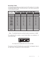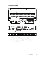
1
A-Net Interface Card User Guide P/N 9310 1017 0001F rev. 1.00 © 2007 Aviom, Inc. Certifications ETL/cETL Listed EMC: EN 55103-1, EN 55103-2, SAA AS/NZS 1053 Conforms to: IEC 60065, EN 60065, UL 60065 Certified to: CAN/CSA E60065, KETI RoHS Status: Pb-free Notice of Rights All rights reserved. No part of this document may be reproduced or transmitted in any form or by any means—electronic, mechanical, photocopy, recording, or otherwise—without written permission of Aviom, Inc. Trademarks Aviom and the Aviom logo are trademarks of Aviom, Inc. A-Net and the A-Net logo are trademarks of Aviom, Inc. Pro16, Pro64, and Virtual Data Cables are trademarks of Aviom, Inc. All other trademarks are the property of their respective owners. Information in this document is subject to change without notice. Copyright ©2007 Aviom, Inc. Printed in USA ii WARNING! ! NO USER SERVICEABLE PARTS INSIDE REFER SERVICING TO QUALIFIED SERVICE PERSONNEL ONLY • To reduce the risk of fire or electrical shock, do not expose this product to rain or other types of moisture. • Operating Temperature: 10˚C to 50˚C (50˚F to 122˚F) CAUTION Risk of electric shock! Do Not Open AVIS: Risque de choc electrique! Ne pas ouvrir WARNING! To reduce the risk of fire or electric shock do not expose this product to rain or moisture. CAUTION: • Using any audio system at high volume levels can cause permanent damage to your hearing. • Set your system volume as low as possible. • Avoid prolonged exposure to excessive sound pressure levels. IMPORTANT: This equipment has been tested and found to comply with the limits for a Class B digital device, pursuant to part 15 of the FCC Rules. These limits are designed to provide reasonable protection against harmful interference in a residential installation. This equipment generates, uses, and can radiate radio frequency energy and, if not installed and used in accordance with the instructions, may cause harmful interference to radio communications. However, there is no guarantee that interference will not occur in a particular installation. If this equipment does cause harmful interference to radio or television reception, which can be determined by turning the equipment off and on, the user is encouraged to try to correct the interference by one or more of the following measures: • Reorient or relocate the receiving antenna. • Increase the separation between the equipment and receiver. • Connect the equipment into an outlet on a circuit different from that to which the receiver is connected. • Consult the dealer or an experienced radio/TV technician for help. Changes or modifications to the product not expressly approved by Aviom, Inc. could void the user’s FCC authority to operate the equipment. iii Important Safety Instructions 1. 2. 3. 4. 5. 6. 7. 8. 9. 10. 11. 12. 13. 14. Read these instructions. Keep these instructions Heed all warnings. Follow all instructions. Do not use this apparatus near water. Clean only with a dry cloth. Do not block any ventilation openings. Install in accordance with the manufacturer’s instructions. Do not install near any heat sources such as radiators, heat registers, stoves, or other apparatus (including amplifiers) that produce heat. Do not defeat the safety purpose of the polarized or groundingtype plug. A polarized plug has two blades with one wider than the other. A grounding type plug has two blades and a third grounding prong. The wide blade or third prong is provided for your safety. If the provided plug does not fit your outlet, consult an electrician for replacement of the obsolete outlet. Protect the power cord from being walked on or pinched, particularly at plugs, convenience receptacles, and the point where they exit the apparatus. Only use attachments/accessories specified by the manufacturer. Use only with the cart, stand, tripod, bracket, or table specified by the manufacturer, or sold with the apparatus. When a cart is used, use caution when moving the cart/apparatus combination to avoid injury from tip-over. Unplug this apparatus during lightning storms or when unused for long periods of time. Refer all servicing to qualified personnel. Servicing is required when the apparatus has been damaged in any way, such as when the power-supply cord or plug is damaged, liquid has been spilled or objects have fallen into the apparatus, the apparatus has been exposed to rain or moisture, the unit does not operate normally, or it has been dropped. 15. The solid line over dashed line symbol ( the input voltage must be a DC voltage. ) indicates that 16. The box within a box symbol ( ) indicates that the external power supply is double insulated. iv Warranty Information Please record the following information for future reference: Your Authorized Aviom Dealer: Name: Address: Phone: Serial Number of Your Aviom Product: Date of Purchase: Your Authorized Aviom Dealer is your primary source for service and support. The information recorded above will be helpful in communicating with your Authorized Aviom Dealer should you need to contact Aviom Customer Service. If you have any questions concerning the use of this unit, please contact your Authorized Aviom Dealer first. For additional technical support, check the Aviom website at www.Aviom.com. To fulfill warranty requirements, your Aviom product should be serviced only at an authorized Aviom service center. The Aviom serial number label must appear on the outside of the unit, or the Aviom warranty is void. This manual and its contents are copyrighted by Aviom, Inc. All rights are reserved by Aviom, Inc. This document may not, in whole or in part, be copied, photocopied, reproduced, translated, or reduced to any electronic medium or machine-readable form without prior written consent from Aviom, Inc. The software and/or firmware contained within Aviom products is copyrighted and all rights are reserved by Aviom, Inc. Although every effort has been made to ensure the accuracy of the text and illustrations in this manual, no guarantee is made or implied as to the accuracy of the information contained within. Aviom, Inc. Limited Warranty Aviom, Inc. warrants this product against defects in materials and workmanship for a period of one year from the date of the original retail purchase. This warranty does not apply if the equipment has been damaged due to misuse, abuse, accident, or problems with electrical power. The warranty also does not apply if the product has been modified in any way, or if the product serial number has been damaged, modified, or removed. If a defect is discovered, first write or call Aviom, Inc. to obtain a Return Authorization number. No service will be performed on any product returned without prior authorization. Aviom, Inc. will, at its discretion, repair or replace the product at no charge to you. The product must be returned during the warranty period, with transportation charges prepaid to Aviom, Inc., 1157 Phoenixville Pike, Suite 201, West Chester, PA 19380, USA. You must use the product’s original packing materials for shipment. Shipments should be insured for the value of the product. Include your name, address, phone number, description of the problem, and copy of the original bill of sale with the shipment. The Return Authorization number should be written on the outside of the box. THIS LIMITED WARRANTY GIVES YOU SPECIFIC LEGAL RIGHTS. YOU MAY HAVE OTHER RIGHTS, WHICH VARY FROM STATE TO STATE (OR JURISDICTION TO JURISDICTION). AVIOM’S RESPONSIBILITY FOR MALFUNCTIONS AND DEFECTS IN HARDWARE IS LIMITED TO REPAIR AND REPLACEMENT AS SET FORTH IN THIS LIMITED WARRANTY STATEMENT. ALL EXPRESS AND IMPLIED WARRANTIES FOR THE PRODUCT, INCLUDING BUT NOT LIMITED TO ANY IMPLIED WARRANTIES OF MERCHANTABILITY AND FITNESS FOR A PARTICULAR PURPOSE, ARE LIMITED IN DURATION TO THE WARRANTY PERIOD SET FORTH ABOVE. NO WARRANTIES, WHETHER EXPRESS OR IMPLIED, WILL APPLY AFTER SUCH PERIOD. AVIOM, INC. DOES NOT ACCEPT LIABILITY BEYOND THE REMEDIES SET FORTH IN THIS LIMITED WARRANTY DOCUMENT. AVIOM, INC.’S LIABILITY IS LIMITED TO THE REPAIR OR REPLACEMENT, AT OUR OPTION, OF ANY DEFECTIVE PRODUCT, AND SHALL IN NO EVENT INCLUDE INCIDENTAL OR CONSEQUENTIAL DAMAGES OF ANY KIND. SOME STATES DO NOT ALLOW EXCLUSIONS OR LIMITATION OF IMPLIED WARRANTIES OR LIABILITY FOR INCIDENTAL OR CONSEQUENTIAL DAMAGES, SO THE ABOVE LIMITATIONS MAY NOT APPLY TO YOU. vi ! Warning Failure to observe the following warnings may lead to risk of serious injury from fire or electric shock. Before installing the 6416Y2 card, you must refer to the owner’s manual of the host device or to the Yamaha website to verify that your host device supports this card, and to verify the number of cards that can be installed in combination with other Yamaha or third-party cards. • Do not attempt to disassemble or modify the card. Do not apply excessive force to board connectors or other board components. (Mishandling the board may lead to shock, fire hazard, or equipment failure.) • You must turn off the power of your device before you begin installing the 6416Y2 card. • Be sure to disconnect the power cable from the main unit before installing this card (to eliminate shock hazard). ! Caution Failure to observe the following precautions may lead to personal injury, or may result in damage to equipment or other property. • Do not touch the board’s metallic leads (pins) when handling the card. (Pins are sharp and may cause hand cuts.) • The card is electrostatic-sensitive. Before handling the card, you should briefly touch the main unit’s metal casing with your bare hand so as to drain off any static charge from your body. vii Table of Contents Warranty Information�������������������������������������������������������������������������������� v Warning ��������������������������������������������������������������������������������������������������������� vii Caution����������������������������������������������������������������������������������������������������������� vii Welcome����������������������������������������������������������������������������������������������������������� 1 Features������������������������������������������������������������������������������������������������ 1 Package Contents ���������������������������������������������������������������������������� 2 The EtherCon Connector ��������������������������������������������������������������� 2 Cat-5e Cables ������������������������������������������������������������������������������������ 2 DIP Switches ��������������������������������������������������������������������������������������� 3 Compatibility ������������������������������������������������������������������������������������ 3 Cleaning����������������������������������������������������������������������������������������������������������� 4 About A-Net ������������������������������������������������������������������������������������������������� 5 Clocking ����������������������������������������������������������������������������������������������� 6 Control Data ��������������������������������������������������������������������������������������� 6 A-Net Ports������������������������������������������������������������������������������������������� 6 Support For Pro16 Series Products �������������������������������������������� 7 Pro64 User Interface ��������������������������������������������������������������������������������� 8 A-Net Slot �������������������������������������������������������������������������������������������� 8 Slots versus Channels��������������������������������������������������������� 8 Slots and Sample Rate ������������������������������������������������������� 9 A-Net Base Slot��������������������������������������������������������������������������������� 10 A-Net Slot Example ����������������������������������������������������������� 11 Network Modes������������������������������������������������������������������������������� 13 Auto Mode���������������������������������������������������������������������������� 13 Manual Mode ���������������������������������������������������������������������� 13 Control Master ������������������������������������������������������������������������������������������ 15 Setting Control Master Status����������������������������������������������������� 16 Control Master Functions ��������������������������������������������������������������������� 17 Enumeration������������������������������������������������������������������������������������� 17 Adding Pro64 Modules to a Network ������������������������� 18 Control Master and Clock Source ��������������������������������������������� 18 Clock Errors �������������������������������������������������������������������������� 19 Network Sample Rate ������������������������������������������������������������������ 19 Changing the Sample Rate��������������������������������������������� 20 Auto/Manual Mode Selection����������������������������������������������������� 20 Changing the Network Mode ��������������������������������������� 21 Managed Mode������������������������������������������������������������������������������� 21 Password Protection ��������������������������������������������������������������������� 21 Installing the 6416Y2 Card������������������������������������������������������������������� 23 Installing Multiple 6416Y2 Cards ��������������������������������� 24 6416Y2 Card Components��������������������������������������������������������������������� 25 Front Panel Features ������������������������������������������������������������������������������� 25 viii Thumb Screws ��������������������������������������������������������������������������������� RS-232/422 Port ������������������������������������������������������������������������������ DIP Switches ������������������������������������������������������������������������������������� Clock and Control DIP Switches ����������������������������������������������� Stereo Link DIP Switches ������������������������������������������������� System Lock ������������������������������������������������������������������������� Remote/Local Control ����������������������������������������������������� Local Code Update ����������������������������������������������������������� Control Master/Slave ������������������������������������������������������� A-Net Ports����������������������������������������������������������������������������������������� Front Panel LEDs ����������������������������������������������������������������������������� Auto LED ������������������������������������������������������������������������������� Control Master (CTL) LED ����������������������������������������������� Clock (CLK) LED ������������������������������������������������������������������ Error (ERR) LED ������������������������������������������������������������������� A-Net LED ����������������������������������������������������������������������������� Circuit Board DIP Switches������������������������������������������������������������������� DIP Switch Block Functions ������������������������������������������� DIP Switch Functions ����������������������������������������������������������������������������� DIP Switch Block 1 (SW1) ������������������������������������������������������������� DIP Switch Blocks 3 and 4 (SW3, SW4) ������������������������������������� Baud Rate Table ����������������������������������������������������������������� DIP Switch Block 8 (SW8) ������������������������������������������������������������� VDC Slot Assignments - Backplane VDC Port ��������� VDC Slot Assignments - Front Panel VDC Port��������� MY8 and MY16 Mode Operation ��������������������������������� DIP Switch Block 9 (SW9)�������������������������������������������������������������� Network Mode (Auto/Manual)�������������������������������������� A-Net Transmit Settings (Manual Mode) ������������������ A-Net Receive Settings (Manual Mode) ��������������������� A-Net Transmit Base Slot Settings ������������������������������ A-Net Receive Base Slot Settings ��������������������������������� Managed Mode ������������������������������������������������������������������ Remote Control of Yamaha Mic Preamps�������������������������������������� Baud Rates����������������������������������������������������������������������������������������� Setting Up ����������������������������������������������������������������������������������������� Connection Example ������������������������������������������������������ RS-232/422 Pinout ������������������������������������������������������������������������� Dimensions�������������������������������������������������������������������������������������������������� DIP Switch Templates ����������������������������������������������������������������������������� Specifications��������������������������������������������������������������������������������������������� 6416Y2 Card Block Diagram����������������������������������������������������������������� Index ��������������������������������������������������������������������������������������������������������������� 25 25 26 26 27 27 27 27 27 28 28 28 28 29 29 29 30 30 31 31 32 33 34 34 35 36 36 37 37 37 37 38 38 39 39 40 41 42 44 46 48 49 50 ix Welcome Thank you for purchasing the 6416Y2 A-Net Interface Card for use with Yamaha® digital products that support the mini-YGDAI (MY) card format. This User Guide is designed to familiarize you with the features and functions of your new Pro64™ product. In developing the Pro64 Series, we have made every effort to make the user interface as easy to use and understand as possible. We encourage you to read the manual completely, as some of the powerful features of your new product may not be immediately apparent. Features The 6416Y2 A-Net Interface Card is a 16-channel Pro64 A-Net® I/O expansion card for Yamaha’s digital devices including digital mixing consoles and the Digital Mix Engine™ (DME) products. It provides a host of professional features designed to make audio networking with Pro64 Series products easy to set up and configure in a variety of professional audio situations. 6416Y2 A-Net Interface Card Features: • Compatible with Yamaha mini-YGDAI (MY) expansion card format • Sixteen input and output channels (Note: 8 channels only on the PM1D console) • Inputs from the console can be individually activated into the Pro64 network • A-Net base slot range can be independently set for inputs and output banks • The 6416Y2 card can be both the Pro64 network Control Master and the network Clock Master • Flexible and robust clocking allows simple console-toconsole digital connections • Front-panel Stereo Link DIP switches for channel pairing for use with Pro16 Personal Mixers • Two A-Net network ports • EtherCon® RJ45 network connectors • Support for Pro64 Virtual Data Cables™ (VDC™) • Variable sample rates: 44.1/48kHz or 88.2/96kHz • RS-232/422 Virtual Data Cable I/O (compatible with the Yamaha remote control protocol) • Multiple cards can be installed per console or DME About Your Pro 64 Product ON Package Contents Check the contents of the shipping box carefully before making connections and continuing with installation. The contents of the 6416Y2 A-Net Interface Card box includes: • One 6416Y2 A-Net Interface Card • User Guide P Note Retain the protective bag that encloses the 6416Y2 card. The card is static-sensitive. Use the bag whenever the card will be transported without being installed in a Yamaha device. The EtherCon Connector Pro64 Series products feature locking connectors for all network I/O. The Neutrik® EtherCon® connector is a dual RJ45-type connector that can receive a standard Category 5e cable or a cable fitted with the special locking EtherCon connector. When using a standard Cat-5e cable, plug the cable into the center of the EtherCon jack; release the cable by pressing on the small plastic tab built into the cable connector. The locking EtherCon connector is similar to an XLR plug, the kind commonly used on microphone cables. Insert an EtherCon-equipped cable into the jack until it clicks and locks in place. To remove the cable, press on the metal release tab at the top of the panel-mounted EtherCon jack and pull the connector outward. B RS–232/422 1 2 3 4 5 6 7 8 A 9 10 11 12 STEREO LINK 16Y2 The 6416Y2 has CLK two A-Net labeled A and B. AUTO CTLports, ERR Cat-5e Cables All Cat-5e connections between A-Net devices should use Unshielded Twisted Pair (UTP) cable. The cable can be of the stranded or solid type; solid wire performs better over long distances, while stranded wire is About Your Pro 64 Product more flexible and easier to manipulate and therefore easier to work with in a live performance situation. Cables designated as Cat-5e in Pro64 documentation can be interchanged with any Cat-6 (or better) cable. Cables will be referred to simply as “Cat-5e.” Connectors on Cat-5e cables used with Pro64 devices can be of the standard RJ45 variety or locking Neutrik EtherCon type. DIP Switches Illustrations of Pro64 DIP switch components in this document will indicate the switch handles in black. In this diagram, all switches are in the down position. Compatibility The Aviom 6416Y2 A-Net Interface Card is compatible with the following Yamaha devices: Device Mini-YGDAI Expansion Slots AW2816 1 AW4416 1 AW2400 1 O1V96 1 O2R96 4 DM1000 2 DM2000 6 DME24N 2 DME64N 4 PM5D/PM5D-RH 4 DSP5D 2 PM1D (8 channels only) 8 M7CL-32, M7CL-48 3 About Your Pro 64 Product Cleaning Before cleaning a Pro64 product, turn off the power switch and unplug the unit from the AC power source. To clean the surface of the Pro64 product use a clean, soft lint-free cloth that has been slightly moistened with water only. For tougher dirt, use a cloth slightly dampened with water or with a mild detergent. Always be sure to dry the surface of the unit before proceeding with use. When cleaning your Aviom products, never spray cleaners directly onto the product surfaces. Instead, spray a small amount of the cleaning solution onto a clean cloth first. Then use the dampened cloth to clean the product. Never use solvents or abrasive cleaners on the finished surfaces of your Aviom products. About Your Pro 64 Product About A-Net Aviom’s A-Net® is the only networking technology conceived, designed, and optimized for managing and distributing audio using ordinary Cat-5e cables. As implemented in the Pro64™ Series products, A-Net can transmit up to 128 channels of uncompressed 24-bit audio with the reliability and fidelity of analog, and the power and flexibility of a true digital network. Pro64 A-Net allows variable sample rates in three ranges, from 44.1kHz± to 192kHz±, with ultra-low latency, jitter, and wander. Pro64 devices can be connected in any combination of serial (daisy-chain) or parallel (star) topologies. Cable runs between Pro64 devices can be up to 400 feet (120 meters) on Cat-5e, and miles on fiber optics (with Aviom fibercapable equipment). Because A-Net is designed specifically for audio, the technological limitations of Ethernet and Ethernet-based products are removed, while audio performance and system flexibility are increased. A-Net incorporates Aviom’s unique patented and patent-pending algorithms for controlling clock jitter and wander, as well as system-wide latency— regardless of an installation’s size, design, or clocking setup. A-Net offers significant advantages in fidelity, performance, and flexibility over Ethernet-based products. A-Net uses the “physical” layer of Ethernet, but it eliminates all the protocol elements that are designed for computers and IT-style networking. In audio applications, these other layers reduce efficiency, impose system restrictions, and introduce latency and timing instability. By eliminating Ethernet data structures, A-Net creates a superior network, with enhanced audio performance. With A-Net and the Pro64 Series, Aviom continues to break new ground in the design and development of innovative digital audio networking technologies and solutions. Pro64 Series Supported Sample Rates Sample Rate Minimum Maximum 1x 44.1/48kHz 39.7kHz 52kHz 2x 88.2/96kHz 79.4kHz 104kHz 4x 176.4/192kHz 158.8kHz 208kHz Cat-5e, Cat-6, or better, Unshielded Twisted Pair (UTP) cable About A-Net Clocking The Pro64 network offers the most flexible clocking and synchronization options in the industry. Pro64 devices support three ranges of variable sample rates, from 44.1/48kHz± to 192kHz±. Because no sample rate converters are used, audio transmission is kept fast and clean, eliminating the audio artifacts and signal degradation inherent to sample rate conversion—even when syncing to an external clock source. Any Pro64 I/O module can be designated the Clock Master for the network, generating and distributing its internal clock. Digital I/O modules are capable of syncing to and distributing an external clock from a Word Clock or AES3 source. Control Data The Pro64 Series has built-in, dedicated bandwidth for 14 channels of non-audio control data through the use of Aviom’s innovative Virtual Data Cables™. These data streams are always available to carry MIDI, RS-232, RS-422, or GPIO (General Purpose I/O), and they never compete with the audio channels for network resources, regardless of the system configuration. (Not all VDC™ data types are supported on every Pro64 module.) Because VDC inputs are simply incorporated into the A-Net stream, these control signals can be transmitted over very long cable runs and even across an entire Pro64 network, significantly expanding the applications possible with MIDI, RS-232/422, and GPIO. And as with audio signals, VDC control data can be input anywhere and output anywhere else in the network. A-Net Ports Pro64 I/O modules have dual A-Net ports, labeled A and B. Both ports carry a bidirectional A-Net stream at all times. (That is, both ports are always transmitting and receiving A-Net data.) Pro64 networks can be configured in one of two operational modes, Auto Mode or Manual Mode, depending on the requirements of a particular system. In Auto Mode, there are no connection rules; connect a Cat-5e cable to either the A or B port and the system does the rest. Auto Mode provides a true audio network with 64 available “Slots” for transporting audio (at 44.1/48kHz). Every audio Slot is available everywhere in the system, with no upstream/downstream restrictions. In Manual Mode, the Pro64 network becomes a 64x64 system (at 48kHz), similar to a traditional stage-to-FOH snake. At every point in the Manual About A-Net Mode network, two 64-channel streams are available on the cable and in each module. The configuration of the cables and ports has an impact on the makeup of the network and the distribution of audio signals. The user can direct A-Net data from an input module to a specific port (A, B, or both). Output modules can be configured to output audio signals from a specific port (A or B). Support For Pro16 Series Products Pro64 Series products can be combined with Pro16™ Series output products such as the Pro16 Monitor Mixing System by adding the Pro64 ASI A-Net Systems Interface. This 1U module converts Pro64 data to Pro16 data, providing up to four streams of 16-channel data (depending on the Pro64 sample rate) that can be used with A-16II and A-16R Personal Mixers, A-Net Distributors, and AN-16/o Output Modules. The ASI is not compatible with the A-Net output of Pro16 input devices such as the AN-16/i, AN-16/i-M, the Y1 console interface card (for Yamaha digital products) and D-16c card (for DiGiCo® digital products). About A-Net Pro64 User Interface This section outlines some basic concepts of operation for Pro64 products. Pro64 I/O devices have some common user interface elements that make setting up an audio network easy to understand. Although the 6416Y2 is set up using DIP switches, its interface elements are similar to other Pro64 hardware I/O modules that use buttons and LEDs for comparable features (seen in some of the examples). Any combination of Pro64 devices can be used when setting up a network. A-Net Slot Pro64 I/O devices come in a variety of configurations (8‑channel, 16‑channel, etc.). To allow a large number of hardware audio input devices to be available to the Pro64 audio network, Aviom has implemented the concept of the A-Net Slot to simplify the configuration of potentially complex audio networks. Simply put, an A-Net Slot is a place in the network where an audio input resource (analog or digital) is assigned. A Pro64 audio network will always have a finite number of A-Net Slots available that can be addressed by an unlimited number of hardware channels. The actual number of available Slots is determined by the current sample rate. Slots versus Channels You might be wondering why Aviom chose to refer to the audio I/O resources in the Pro64 Series products as ‘’Slots.” Why not just call them “channels”? We did this to avoid confusion between references to hardware audio resources and network audio resources. The word ‘’channel’’ is ambiguous and may cause confusion when configuring an audio network. “Channel” appears in many contexts, including audio mixing consoles, mic preamps, DSP processors, and DAW software. We use the word ‘’channel’’ when referring to the physical audio inputs—analog or digital—on a piece of hardware (such as the 16 linelevel XLR input jacks on the 6416i Input Module or a Yamaha console resource such as a direct output or aux bus send). Each of these audio inputs can be made active and added to the network individually, and it is only when activated that they use any network resources (the A-Net Slots). To allow this functionality, Pro64 products separate the hardware resources from the available network resources by giving each hardware input channel a switch or button that allows it to be added to the Pro 64 User Interface network as needed. (The 6416Y2 card uses DIP switches.) It is these activated hardware resources that are being referred to as “Slots.” Pro64 audio networks can potentially have a greater number of audio channels and hardware I/O devices connected than the network can make use of at one time. This provides flexibility without requiring constant re-patching. Keep in mind that a Pro64 A-Net network can only manage a specific number of Slots at a time, and this number varies with the sample rate being used. The maximums are 64 Slots in Auto Mode at the 48kHz sampling rate and 64x64 Slots in Manual Mode at 48kHz. In summary, think of “channels” as hardware resources that can be added to the network as needed and “Slots” as locations within the digital audio network pipeline that A-Net uses to move data throughout the network. Slots and Sample Rate The current system-wide sample rate will determine the number of A-Net Slots that are available. Auto Mode and Manual Mode have the same number of Slots at each sample rate; only the direction of the data is different. Sample Rate 44.1kHz 48kHz 88.2kHz 96kHz 176.4kHz 192kHz A-Net Slots 64 64 32 32 16 16 Yamaha Compatibility Yes Yes Yes Yes No No Even though the network sample rate may change the available number of A-Net Slots, the capacity of a hardware device does not change. That is, a 16-channel input module in a 96kHz network can still have all of its channels activated; all of its physical inputs can operate at 96kHz. The current sample rate will also affect the display of available A-Net Slot ranges. Slot ranges will always have the same maximum number as seen in the sample rate chart. At 96kHz, for example, only Slots 1 through 32 are available; the Slot range from 33 to 64 is inactive and unavailable at 96kHz. Slot ranges outside the maximum for the current sample rate can be selected, but attempting to activate a channel in an unavailable range will result in an error message on hardware I/O modules (the selected channel button, A-Net Slot range, and sample rate LEDs will all flash). Note that console interfaces such as the 6416Y2 card have no A-Net Slot displays and cannot display these error messages. Pro 64 User Interface A-Net Base Slot Since the capacity of the Pro64 network could be as high as 64 A-Net Slots, Pro64 hardware I/O devices need a way of routing a selected hardware channel to a selected network Slot. The 6416Y2 uses a block of DIP switch (referred to as SW9) to select a base Slot range, in groups of 16 channels. See page 36 for more info on A-Net Slot setup. For Pro64 hardware I/O devices, the upper left corner of the front panel contains a dedicated A-Net Slot display. Its associated inc/dec buttons are used to select a range of Slots that the hardware device will address. The A-Net Slot display and its inc/dec buttons are used to set the base Slot for a Pro64 I/O module. The following tables show examples of the channel-to-Slot correlation for 16-channel Pro64 Series modules in a network running at the 48kHz sample rate. The numbers in the Base Slot column will appear in the A-Net Slot display of all I/O modules (the 6416Y2 has no Slot display). 16-Channel Pro64 Module Hardware Channels 1 2 3 4 5 6 Base Slot 7 8 9 10 11 12 13 14 15 16 A-Net Slot 1 1 17 17 18 19 20 21 22 23 24 25 26 27 28 29 30 31 32 2 3 4 5 6 7 8 9 10 11 12 13 14 15 16 33 33 34 35 36 37 38 39 40 41 42 43 44 45 46 47 48 49 49 50 51 52 53 54 55 56 57 58 59 60 61 62 63 64 The use of Slot assignments allows for easy reconfiguration of audio networks and sharing of hardware I/O resources and data without physical re-patching. 10 Pro 64 User Interface A-Net Slot Example The following example shows the power of the Pro64 network and the A-Net Slots concept. The range of A-Net Slots used in the example has been limited to the group from 1 to 16 for simplicity. This graphic represents a Pro64 product set to Slot range 1. Slot Channel 1 1 2 3 4 5 6 7 8 9 10 11 12 13 14 15 16 One 16-channel input module is placed in each of four rooms of a production facility, designated as Studios A, B, C, and D. One 16‑channel output module is installed in the facility’s Studio E. All modules are set to Slot range 1 (shown in grey). Studio A Inputs Slot Channel 1 1 2 3 4 5 6 7 8 9 10 11 12 13 14 15 16 Studio B Inputs Slot Channel 1 1 2 3 4 5 6 7 8 9 10 11 12 13 14 15 16 Studio C Inputs Slot Channel 1 1 2 3 4 5 6 7 8 9 10 11 12 13 14 15 16 Studio D Inputs Slot Channel 1 1 2 3 4 5 6 7 8 9 10 11 12 13 14 15 16 Studio E Outputs Slot Channel 1 1 2 3 4 5 6 7 8 9 10 11 12 13 14 15 16 Pro 64 User Interface 11 By activating a group of channels on each of the four input modules, a total of sixteen inputs are used (indicated by reverse text). All of these inputs are available on the network at every output module. The operator in Studio E can use the sixteen inputs from Studios A, B, C, and D simultaneously. The order in which the Pro64 devices are connected is irrelevant. Studio A Inputs Slot 1 Channel 1 2 3 4 5 6 7 8 9 10 11 12 13 14 15 16 Studio B Inputs Slot 1 Channel 1 2 3 4 5 6 7 8 9 10 11 12 13 14 15 16 Studio C Inputs Slot 1 Channel 1 2 3 4 5 6 7 8 9 10 11 12 13 14 15 16 Studio D Inputs Slot 1 Channel 1 2 3 4 5 6 7 8 9 10 11 12 13 14 15 16 Studio E Outputs Slot 1 12 Channel 1 2 3 4 Pro 64 User Interface 5 6 7 8 9 10 11 12 13 14 15 16 Network Modes A Pro64 audio network can be set to operate in one of two modes, Auto or Manual. The network mode can be selected on the front panel of the I/O device designated as the system’s Control Master or from the 6416Y2 DIP switches in block SW9. See page 36 for more info on A-Net Slot setup. Both modes are fully bidirectional at all times, regardless of the system layout or design. Auto Mode Pro64’s Auto Mode takes most of the work out of managing resources in an audio network. This is the “everything everywhere” mode. Input channels made active in the network can be seen and used by all devices in the network, regardless of how the modules are connected and regardless of the physical location of any module. Output modules do not need to follow input modules as in a traditional analog system. In Auto Mode, both A-Net ports (A and B) function identically. Once configured for Auto Mode, the system ensures that only one hardware input channel is activated into a given A-Net Slot. There is no limit to the number of hardware output channels that can use a given A-Net Slot. The actual number of available Slots is determined by the current sample rate. The maximum number of available Slots (active channels) is 64 at the 44.1/48kHz sample rate. Sample Rate 44.1/48kHz 88.2/96kHz 176.4/192kHz Available A-Net Slots in Auto Mode 64 32 16 Manual Mode When more than 64 channels are needed in a network, Manual Mode can be used to provide configurations of up to 64x64 channels. Two unique 64-channel streams are available at each module. In Manual Mode, the A and B A-Net port connections can be used to direct and route A-Net data. Pro64 input modules can send their audio inputs to either or both A-Net ports, while output modules can listen to data from either port. For a traditional stage-to-FOH snake system, this allows the user to configure a system with up to 64 sends from the stage and another unique stream of up to 64 returns to the stage. Pro 64 User Interface 13 Manual Mode operation removes the restrictions of unique channel-toSlot-range relationships found in Auto Mode. Slots can be overwritten, allowing the user to replace channels from one part of the network with new data. This means that, while no more than 128 channels can be in the network at a particular location, there is no practical limit to the total number of audio channels in the system. The number of available Slots in Manual Mode is dependent upon the current sample rate. Sample Rate 44.1/48kHz 88.2/96kHz 176.4/192kHz * Available A-Net Slots in Manual Mode 64x64 32x32 16x16 * * The Pro64 176.4 and 192kHZ network sample rates are not compatible with Yamaha devices. 14 Pro 64 User Interface Control Master In every Pro64 network, one device will always be designated as the Control Master, the device that manages all A-Net resources for the network. The Control Master can be any I/O module in the network, and can be assigned or changed by the user as needed. Only one device can be assigned as Control Master in a Pro64 network at a time; an A-Net Pro64 network cannot function without a Control Master. The functions of the Control Master include: • System resource and information management • Setting network mode (Auto or Manual) • Management of active channels (Slots) in Auto Mode • System-level command and control functions • Keeping track of all Pro64 devices in the network (by type and quantity) • Control of the current system-wide sample rate • Clock Master (analog modules only) • System lock via password on/off • Management of Virtual Data Cable (VDC) resources • Management of stereo link status • Requests to enter Managed Mode The Control Master status is identified with a red LED on the front panel of the device currently assigned as the Control Master. Depending on the type of device (rack-mounted I/O module or console interface card), the method used for designating Control Master status may be different. The Control Master LED is labeled CTL on the 6416Y2 card. RS–232/422 ON 1 2 3 4 5 6 7 8 B A 9 10 11 12 STEREO LINK 6416Y2 AUTO CLK CTL ERR The Control Master LED (abbreviated as “CTL”) on the 6416Y2 card Control Master 15 Only one device in a Pro64 network can be designated as the Control Master. Here, a Pro64 I/O module is shown. Setting Control Master Status Setting the 6416Y2 to be the network Control Master is done using the DIP switches found on the front panel. The Control Master is set with switch 12, found in the same DIP switch block as the Stereo Link section of the interface. RS–232/422 ON 1 2 3 4 5 6 7 8 B A 9 10 11 12 STEREO LINK 6416Y2 AUTO CLK CTL ERR DIP switch 12 (shown in black) is used to set the Control Master status for a 6416Y2 card. Move DIP switch 12 to the down position to make the 6416Y2 card the Control Master. P Note: When a 6416Y2 card is set to be Control Master, it is automatically set to be the Clock Master. 16 Control Master Control Master Functions This section describes the individual functions of the Control Master device in a Pro64 network. Enumeration When the Control Master is powered on, its first job is to identify and count all connected A-Net modules in the network in a process called enumeration. The time for this process will vary based upon the number of Pro64 modules in a system. This process cannot begin until the host Yamaha device has finished its own power-up cycle when a 6416Y2 A-Net Interface Card is the Control Master. Enumeration is an automated process performed by the command and control portion of the A-Net software. There are no user-controllable functions or settings. During the enumeration process, all connected A-Net modules will flash their blue A-Net LEDs, indicating that a request to be added to the network is being made. Once granted entry by the Control Master, the individual module’s blue A-Net LED will light solid to indicate that it is now receiving valid A-Net packets and is part of the Pro64 network. RS–232/422 ON 1 2 3 4 5 6 7 8 B A 9 10 11 12 STEREO LINK 6416Y2 AUTO CLK CTL ERR The blue LED is used to indicate network status. If valid A-Net packets are not received, the module will reset and wait until a valid A-Net stream is detected. During enumeration, any conflicts will also be resolved. For example, consider a new Auto Mode installation using eight input modules set to the same A-Net Slot range with all channels activated during a bench configuration. When all these input modules are connected and then powered up, only one of them will be allowed to have all 16 channels activated. The remaining seven modules will have their audio channels deactivated. Control Master 17 Adding Pro64 Modules to a Network When a new Pro64 device is added to an existing network, the new device makes a request to the Control Master for inclusion in the network. During this time, the new module’s blue A-Net LED will flash. When the new module has been enumerated by the Control Master, its blue A-Net LED will then light solidly to indicate that the Control Master has granted the module access to the network. Adding a new module will interrupt network operation briefly. Control Master and Clock Source By default, the device designated as Control Master in a network consisting of all analog modules is also the device in control of the network master clock. The front-panel Clock Master LED lights to indicate that a module is designated as the master clock device. RS–232/422 ON 1 2 3 4 5 6 7 8 B A 9 10 11 12 STEREO LINK 6416Y2 AUTO CLK CTL ERR The red Clock Master LED lights when a Pro64 device is the Control Master. When an analog I/O module is the Control Master, there is no other analog module that can be used as a clock source in an all-analog network. When a 6416Y2 console interface card is part of an audio network, the 6416Y2 can be used as a Clock Master for the network; it 18 Control Master must also be the network’s Control Master to have control over clock functions. When a 6416Y2 card is the Clock Master, its clock is derived from the Yamaha host device. (Multiple 6416Y2 cards can be used in a Yamaha host device, but only one can be set to be Control Master and Clock Master.) External clock sources on digital modules can include: • The internal clock reference from the Yamaha device • Word Clock received via the external Word Clock inputs on a Yamaha device • Word Clock via the dedicated BNC Word Clock jack on a Pro64 digital I/O device, such as the 6416dio Digital I/O Module • AES3 (AES/EBU) from an AES3 digital stream on a Pro64 digital I/O module Clock Errors If a clock error occurs, the Clock Master LED will blink indicating that an error has occurred. Common causes for a clock error include: • Attempting to change the sample rate on a device other than the Clock Master • Attempting to change the clock source when the network is password protected • Removing or changing external clock sources on a digital I/O module • Incorrect configuration of an external clock source on a digital I/O module Network Sample Rate When an analog device is the Control Master, the Control Master is automatically designated as the Clock Master. It will remain the Clock Master until a different analog module is made the Control Master or until a digital module such as the 6416Y2 card is added to the network and is assigned to be the Control Master and Clock Master. The network’s internal master clock is derived from the sample rate currently in use. The sample rate also affects the total number of available A-Net Slots available for use in the network. The Clock Master LED on the 6416Y2 card (labeled CLK) will light automatically when its host is powered on if the 6416Y2 card is Control Master and Clock Master for the Pro64 network. When a 6416Y2 card is Control Master, the network clock is derived from the Yamaha host Control Master 19 device. That clock reference can be the Yamaha host’s internal clock or an external clock to which the Yamaha host device is synced. Changes to the host’s sample rate will affect available A-Net Slots. The Sample Rate section of a rack-mounted hardware I/O module’s front-panel interface (e.g., 6416i Input Module) includes a group of LED indicators for displaying the current network sample rate. One LED will be lit at all times. The 6416Y2 card has no such LEDs. However, the current sample rate information will be sent to all Pro64 network devices when a 6416Y2 card is Control Master/Clock Master. The sample rate display on Pro64 I/O modules will display the current networkwide sample rate when a 6416Y2 A-Net Interface Card is the Clock Master, receiving its clock from the Yamaha host device. The current sample rate for the network will be displayed on all I/O modules in the network, and will update to reflect any changes made from the Yamaha host (such as changing the sample rate from 48kHz to 96kHz). Only one sample rate can be used at a time in a Pro64 network. Changing the Sample Rate Changing the sample rate when a 6416Y2 A-Net Interface Card is the Clock Master is done from within the Yamaha user interface. Changing the sample rate will affect the number of available A-Net Slots when the sample rate changes from the 1x range (44.1/48kHz), to the 2x range (88.2/96kHz), or vice versa. Note that only sample rates up to 96kHz are supported by Yamaha digital devices. Auto/Manual Mode Selection The Control Master can be used to set the current network mode to Auto or Manual. As with the system-wide sample rate, the network mode is also a global setting. Only one Pro64 device can be Control Master in a network. Changes to the network mode must be made from the Control Master. The 6416Y2 is configured using DIP switches, with DIP Switch Block 9 (SW9) on the circuit board used to set the network mode. This means 20 Control Master that changes to the Pro64 network mode require the host Yamaha device to be powered down so that the 6416Y2 card can be removed. Changing the Network Mode To change the network mode from a 6416Y2 card that is the network Control Master, move switch 1 in Switch Block SW9 to the desired position, down for Auto Mode, or up for Manual Mode. The Control Master will update the display on all modules in the network to reflect the mode change once the network is restarted. Managed Mode Managed Mode requires the use of a computer with the Pro64 network for tasks such as software/firmware updates, system monitoring, control, and editing. The Control Master is the only module that can allow the network to enter Managed Mode. Entering Managed Mode requires that the 6416Y2 card be the network’s Control Master. DIP Switch Block 9 (SW9) is used to set the network for Managed Mode operation. This means that changes to the Pro64 network mode require the host Yamaha device to be powered down so that the 6416Y2 card can be removed. To change the network mode from a 6416Y2 card that is the network Control Master, move switch 10 in SW9 to the up position Once the network enters Managed Mode, all rack-mount I/O modules will light their Managed LEDs. Note that the 6416Y2 does not have a Managed Mode LED. To manage a Pro64 network with a PC, the PC needs to be connected to the Control Master using a DB9 null modem cable connected to the RS-232 port. The 6416Y2 card must be set for RS-232 operation and not for RS-422; this is done from DIP Switch Block 4 (SW4) on the circuit board. See page 32 for more information. Exiting Managed Mode also requires that the host Yamaha device be powered down so that the 6416Y2 card can be removed to have DIP switch settings changed. Password Protection A Pro64 network can be password protected from the Control Master only. Once protected, the front-panel interface on all modules is locked, preventing changes to A-Net Slots, sample rate, clock source, channel activation, stereo links, and Virtual Data Cable assignments. Hardware Control Master 21 switches, such as gain settings on input and output modules, and rear-panel DIP switches are in the analog domain and are not affected. Password protection remains in force even when a system is power cycled. All Pro64 hardware I/O devices except console interface cards ship with a default password. The 6416Y2 card can be used to lock the network, but no password is available. To lock the Pro64 network, move switch 9 in the front-panel DIP switch block to the down position. Changes to the network lock status will be instantly reflected on other network modules. No edits are possible until the network is unlocked. When the 6416Y2 card is Control Master, simply move switch 9 in the front-panel DIP switch block to the up position to unlock the network and allow changes to be made. RS–232/422 ON 1 2 3 4 5 6 7 8 B A 9 10 11 12 STEREO LINK 6416Y2 AUTO CLK CTL ERR DIP Switch 9 on the front panel can be used to lock the Pro64 network. 22 Control Master Installing the 6416Y2 Card The 6416Y2 card can be used in any MY (mini-YGDAI) expansion slot in a Yamaha digital mixing console or compatible digital product (see the list on page 3). The specific number of available expansion slots varies with each model. Yamaha expansion slots are identified by number, starting with “Slot 1.” Within an MY expansion slot, its audio resources are referred to as “channels,” numbered from 1 to 16. (The PM1D is limited to 8-channel operation.) P Note The 6416Y2 card is electrostatic-sensitive. Before handling the card, you should briefly touch the main (host) unit’s metal casing with your bare hand to drain off any static charge from your body. The components of the card are indicated in the diagram below. Multi-pin connector Align sides of 6416Y2 card with the guides in the MY expansion slot. Front panel DIP switches, connectors, and LEDs Thumb screws P Note: Before installing the 6416Y2 card in a compatible Yamaha digital device, be sure to read the DIP switch configuration section of this User Guide (page 30). Some Pro64 network and audio routing settings cannot be changed once the card has been connected to the Yamaha device since they are changed via DIP switches found on the circuit board of the card itself. Installation 23 To install the 6416Y2 card: • Start with the power to the Yamaha digital device off. • Remove the Yamaha device’s power cord from the wall receptacle. • Remove the cover plate on the Yamaha device’s expansion slot to expose the expansion connections. • Discharge any built-up static charge by touching the metal casing of the host Yamaha unit. • Remove the 6416Y2 card from its protective anti-static sleeve. • Ensure that the 6416Y2 card DIP switches are set properly for your application at this time. • Slide the 6416Y2 card into place, aligning the sides of the card with the support guides in the expansion slot. • Press the 6416Y2 card firmly in place to attach the multi-pin connectors on the card to those on the expansion slot backplane on the Yamaha device. • Tighten the thumb screws on the 6416Y2 to secure it. • Power up the Yamaha digital device. • Connect the 6416Y2 to a Pro64 network. Once the Aviom expansion card has had its DIP switches configured and is installed in the Yamaha host device, all audio routing to/from the 6416Y2 A-Net Interface Card is done from within the Yamaha device’s user interface. Consult the documentation that came with your Yamaha product for more specific signal routing information. P Note: Always power off the Yamaha host device before removing the 6416Y2 card. Installing Multiple 6416Y2 Cards A Yamaha host device can support as many Pro64 A-Net cards as it has available MY (mini-YGDAI) expansion slots. When multiple 6416Y2 A‑Net Interface Cards are installed in a Yamaha host device, they need to be connected via their A-Net ports. Simply use a short Cat-5e cable to interconnect the 6416Y2 cards. A list of compatible Yamaha products and the number of available MY expansion slots on each appears on page 3. 24 Installation 6416Y2 Card Components RS–232/422 B v A y ON w STEREO LINK 6416Y2 1. 2. 3. 4. 5. 6. 7. 1 2 3 4 5 6 7 8 9 10 11 12 x z AUTO CLK CTL ERR Thumb Screws RS-232/422 DB9 connector DIP Switches 1-8 – Stereo Link DIP Switches 9-12 – system control Locking EtherCon RJ45 A-Net connections Auto Mode, Clock Master (CLK), Control Master (CTL), and Error (ERR) LEDs A-Net active LED Front Panel Features This section describes the features and functions of the front panel of the 6416Y2 A-Net card interface. Thumb Screws The two permanently attached thumb screws on the 6416Y2 card are used to secure the card to an expansion slot in the Yamaha device. Always make sure that both thumb screws are firmly attached when using or transporting the Yamaha device with a 6416Y2 installed. RS-232/422 Port The nine-pin DB9 RS-232/422 port can be configured to send/receive control data from the Yamaha interface or from the Pro64 Virtual Data Cables. Selection of RS-232 or RS-422 and baud rate configuration is done via the DIP switches on the circuit board of the 6416Y2 card. Each type of control data communication—RS-232 and RS-422— requires a unique cable. RS-232 requires a null modem cable; RS-422 6416Y2 Features 25 requires a straight-through cable. DIP Switches There is one 12-position DIP switch block on the front panel of the 6416Y2, referred to as SW7 in the diagrams that follow. Note the mounting direction of the DIP switches; to activate a switch on SW7, move it to the down position. The default setting for all switches in this block is up. B RS–232/422 ON 1 2 3 4 5 6 7 8 A 9 10 11 12 STEREO LINK 6416Y2 AUTO CLK CTL ERR In this diagram, channels 7-8, 13-14, and 15-16 are stereo linked. This 6416Y2 is also the network Control Master. DIP switch handles are indicated in black. Clock and Control DIP Switches Within front panel DIP Switch Block SW7 is a group of four system-level DIP switches. These control the system lock via password, local/remote control, firmware update status, and Control Master vs. Slave status respectively. 26 Switch Function Off (up) Function On (down) 1-8 Single channel control Stereo Link (per channel pair: 1-2, 3-4, etc.) 9 System Unlocked System Locked 10 Local Control Remote PC Control 11 Local Code Update Off (This switch is scanned only at power up.) Local Code Update Active 12 Slave Device Control Master 6416Y2 Features Stereo Link DIP Switches Eight Stereo Link DIP switches are provided allowing odd-even channels to be paired for use with Aviom Pro16 personal monitor products such as the A-16II and A-16R Personal Mixers. (This application requires the ASI A-Net Systems Interface.) Each DIP switch controls a pair of channels. Stereo Link information will be passed to all Pro64 modules. If applicable, a Stereo Link LED will light on Pro64 output modules such as the analog 6416o Output Module and 6416dio Digital I/O Module when stereo information is present in the network. System Lock DIP switch 9 controls the Password Lock feature, allowing all devices in the network to be locked from a single location. Unlike Pro64 hardware I/O devices, there is no way to set a password code on the 6416Y2 card. The Pro64 network is locked/unlocked immediately when the DIP switch is moved. No edits are possible when the network is locked. Remote/Local Control Use DIP switch 10 to set the 6416Y2 card for Local control (up) or Remote PC control (down). All DIP switch settings are scanned and applied at the time the Yamaha host device is powered up if the 6416Y2 card is set for Local control. DIP switch settings are not scanned and applied when the Yamaha host device starts up if the card is set for Remote control. Local Code Update The Local Code Update DIP switch is used in conjunction with the Pro64 firmware update application. Note that this switch is scanned only when the host Yamaha device is powered up. Changing the position of this DIP switch requires a reboot of the host device for the switch position to be recognized. Control Master/Slave DIP switch 12 is used to set the 6416Y2 card as either the network Control Master (down) or as a slave device (up). Note that only one Pro64 device can be Control Master in a network. Although this DIP switch setting can be changed on the fly, note that the Pro64 network will need to reset if a new Control Master device is selected. Audio and control data are interrupted while the network resets. 6416Y2 Features 27 A-Net Ports Two Pro64 A-Net ports are provided on the 6416Y2 card, labeled A and B. Each port has a Neutrik® EtherCon® connector and can support standard RJ45 cables or those fitted with the heavy-duty EtherCon plug. Multiple 6416Y2 cards can be used in compatible Yamaha devices by linking them together via the A-Net ports with a short Cat-5e jumper cable. Front Panel LEDs A set of five LEDs on the front panel of the 6416Y2 card is used to inform the user of various network conditions and/or error states as described below. Auto LED The Auto LED will be on and lit yellow to indicate that the Pro64 network is running in Auto Mode. In the off state, this LED indicates that the network is operating in Manual or Managed Mode. Control Master (CTL) LED The yellow Control Master (CTL) LED indicates that the 6416Y2 card is set to be the network’s Control Master. A 6416Y2 card set to be the network’s Control Master is automatically set to be the network Clock Master as well. Only one Pro64 device can be set to be the Control Master. When off, this LED state indicates that the card is a slave device. For more info about the Control Master, see page 15. RS–232/422 ON 1 2 3 4 5 6 7 8 B A 9 10 11 12 STEREO LINK 6416Y2 AUTO CLK CTL ERR Here, DIP switch 12 is in the down position, making this 6416Y2 card the Pro64 network Control Master. When DIP switch 12 is in the down position, both the Control Master (CTL) and Clock Master (CLK) LEDs will be lit. This 6416Y2 card is also the Clock Master when it is set to be the Control Master. (DIP switch handles are shown in black.) 28 6416Y2 Features Clock (CLK) LED The Clock (CLK) LED will light yellow when the 6416Y2 card is set to be the Pro64 network’s Control Master, which automatically sets the card to be the network Clock Master. When the 6416Y2 card functions as the network Clock Master, its clock is derived from the Yamaha host device. Only one Clock Master is possible in a Pro64 network. The Clock LED will remain unlit when the 6416Y2 card is a slave device to another clock source (either the Pro64 network internal clock or from an external Word Clock reference connected to a Pro64 digital I/O module such as the 6416dio). Error (ERR) LED The Error LED will light red to indicate errors in enumeration, configuration, or clocking. A-Net LED Whenever a valid A-Net connection is detected, the blue A-Net LED will light solid. The A-Net LED will flash during the network enumeration process as Pro64 devices are added to the network, or during a firmware update. If no valid Pro64 A-Net signal is detected, the A-Net LED remains off. 6416Y2 Features 29 Circuit Board DIP Switches The 6416Y2 A-Net Interface Card is configured using DIP switches. Each block of switches is labeled on the circuit board with the abbreviation “SW” followed by a number. There is one DIP switch block on the front face of the card (SW7), and there are six DIP switch blocks on the card’s circuit board. These will be hidden once the card is installed. The following table lists the functions of the various DIP switch blocks on the 6416Y2. Note the locations of the various switches on the diagram that follows the table. Also note that Switch Block SW7 is on the front panel of the card, facing the user. DIP Switch Block Functions Switch Label Location Total Switches SW1 Circuit board 8 Activation on/off for channels 1-8 from the Yamaha device being routed into the Pro64 network SW2 Circuit board 8 Activation on/off for channels 9-16 from the Yamaha device being routed into the Pro64 network Function(s) SW3 Circuit board 8 Configuration of RS-232/422 Virtual Data Cable (VDC) on Yamaha backplane (not supported on all Yamaha digital products) SW4 Circuit board 8 Configuration of RS-232/422 Virtual Data Cable (VDC) on rear panel of 6416Y2 card SW7 Front panel 12 Stereo Link, Network Password Lock, Local/Remote control, Code Update on/off, Control Master/Slave configuration SW8 Circuit board 10 VDC Port configuration SW9 Circuit board 10 Pro64 Network Mode, Transmit/ Receive Port and Slot selection, Managed Mode on/off P Note: Always power off the Yamaha host device before removing the 6416Y2 card to make changes to any DIP switch settings. 30 DIP Switch Functions SW7 ON 1 2 3 4 5 6 7 8 9 10 SW8 ON ON 1 2 1 2 3 4 5 6 3 4 5 6 7 8 9 10 SW9 7 8 SW3 ON ON 1 2 1 2 3 4 5 6 SW4 7 8 3 4 5 6 7 8 SW1 ON 1 2 SW2 3 4 5 6 7 8 This diagram shows the locations of the 6416Y2 DIP switches. The arrow indicates SW7, on the front of the card. (DIP switch handles are indicated in black.) DIP Switch Functions The individual DIP switch functions for circuit board switch blocks SW1, SW2, SW3, SW4, SW8, and SW9 are detailed in this section. DIP Switch Block 1 (SW1) Use Switch Block 1 (SW1) to activate channels 1-8 on the 6416Y2 card and assign them to Slots within the Pro64 network. In the down position, channels 1-8 are off; move a DIP switch to the up position to activate a channel and assign it to the Pro64 network. The default position for the SW1 DIP switches is down (channel-to-Slot activation is off). P Note: Signals from the Yamaha device cannot be routed into the Pro64 network unless these DIP switches are activated. DIP Switch Functions 31 DIP Switch Block 2 (SW2) Switch Block 2 (SW2) is used to assign channels 9-16 on the 6416Y2 card to Slots in the Pro64 network when operating in MY16 Mode (channels 9-16 are not available in MY8 Mode). In the down position, channels 9-16 are off; move a DIP switch to the up position to activate a channel, which assigns it to a Slot and makes it available throughout the network. P Note: Routing an audio resource from within the Yamaha user interface to the 6416Y2 installed in an expansion slot requires that the SW1 and SW2 Slot activation DIP switch settings be set correctly in order to pass digital information from the Yamaha device to the Pro64 network. The exact Pro64 Slot range to which the channels from the 6416Y2 card are routed is determined by the settings of DIP switches 5 and 6 on block SW9. The default position for the SW2 switches is down (channel-to-Slot activation is off). When operating in MY8 mode, leaving these switches in the down position will help avoid potential Slot availability conflicts with other Pro64 devices in the network. A blank DIP switch template is provided at the end of this User Guide to allow you to record and save 6416Y2 card settings. DIP Switch Blocks 3 and 4 (SW3, SW4) There are two sets of RS-232/422 Virtual Data Cable (VDC) ports available on the 6416Y2 card, one on the backplane of the card itself, SW3, (currently not supported on all Yamaha digital products; consult Yamaha for compatibility information), and another on the front panel of the card, SW4. Baud rates for these ports are independently controlled by DIP Switch Blocks SW3 and SW4 respectively. There are eight DIP switches on each block. The switches on SW3 and SW4 have the following functions. Switch Function Off (down) Function On (up) 1 One Stop Bit Two Stop Bits 2 7 Data Bits 8 Data Bits 3 Parity Even Parity Odd 4 No Parity Parity 5 6 Baud Rate Select 7 See Baud Rate Table 8 32 DIP Switch Functions Baud Rate Table Use the following table to set baud rates for DIP switches 5-8 in either Switch Block SW3 or SW4. The down position is off and the up position is on for each DIP switch. DIP Switches in Block 3 or 4 (SW3, SW4) 8 Baud Rate 5 6 7 8 1200 off off off off 2400 on off off off 4800 off on off off 7200 on on off off 9600 off off on off 14400 on off on off 19200 off on on off 28800 on on on off 38400 off off off on 57600 on off off on 31250 SW7 (MIDI) off on off on ON P Note: The default baud rate used by Yamaha mic preamps is 38400. The individual DIP switches 1in2each 3 4 Switch 5 6 7Block 8 9 are 10 numbered 1-8, from left to right. SW8 ON ON 1 2 1 2 SW3 3 4 5 6 7 8 3 4 5 6 7 8 9 10 SW9 ON This example shows SwitchON Block SW3 set for a baud rate of 57600. 1 2 3 4 5 6 1 2 on3 the 4 56416Y2 6 7 8card appears The pinout of the RS-232/422 jack SW4 later in this document. See page 42 for more information. SW1 7 8 ON 1 2 SW2 3 4 5 6 DIP Switch Functions 33 7 8 DIP Switch Block 8 (SW8) SW8 is used to select either RS-232 or RS-422 operation for the data ports on the 6416Y2 card and to assign these ports to the 14 available VDC Slots in the Pro64 network. Block SW8 has ten individual DIP switches, whose functions are outlined in the table below. DIP Switch Block 8 (SW8) Functions Switch Function Off (down) Function On (up) 1 DB9 port on front of card communicates using RS-232 DB9 port on front of card communicates using RS-422 2 Backplane RS-232/422 VDC Slot Assignment 0 * Backplane RS-232/422 VDC Slot Assignment 0 3 Backplane RS-232/422 VDC Slot Assignment 1 Backplane RS-232/422 VDC Slot Assignment 1 4 Backplane RS-232/422 VDC Slot Assignment 2 Backplane RS-232/422 VDC Slot Assignment 2 5 Front panel RS-232/422 VDC Slot Assignment 0 * Front panel RS-232/422 VDC Slot Assignment 0 6 Front panel RS-232/422 VDC Slot Assignment 1 Front panel RS-232/422 VDC Slot Assignment 1 7 Front panel RS-232/422 VDC Slot Assignment 2 Front panel RS-232/422 VDC Slot Assignment 2 8 Reserved Reserved 9 Reserved Reserved 10 MY8 Mode MY16 Mode * See tables below for specific DIP switch settings for VDC assignments. The default setting for DIP switch 1 is RS-232. VDC connections to the Yamaha backplane (switches 2, 3, and 4, are not supported on all Yamaha digital products; consult Yamaha for compatibility information.) VDC Slot Assignments - Backplane VDC Port Combinations of switches 2, 3, and 4 within SW8 are used to assign Virtual Data Cable Slots for the backplane VDC port. The following table lists the possible settings for the 14 VDC Slots available in a Pro64 network. 34 DIP Switch Functions Note that RS-232/422 communication always requires a pair of Virtual Data Cable Slots and that this pair must always be an odd-even combination of VDCs. The down position is off and the up position is on for each DIP switch. VDC Slot Assignments for the Backplane VDC Port - Switch Block SW8 VDC Slot Pair DIP Switch 2 DIP Switch 3 DIP Switch 4 OFF off off off 1&2 on off off 3&4 off on off 5&6 on on off 7&8 off off on 9 & 10 on off on 11 & 12 off on on 13 & 14 on on on VDC Slot Assignments - Front Panel VDC Port Switches 5, 6, and 7 are used to assign Virtual Data Cable Slots for the front panel RS-232/422 VDC port. The following table lists the possible settings for the 14 VDC Slot assignments available in a Pro64 network. RS-232/422 communication always requires a pair of Virtual Data Cable Slots; this pair must always be an odd-even combination of VDCs. The default setting for DIP switch 1 in block SW8 is RS-232. VDC Slot Assignments for the Front Panel VDC Port - Switch Block SW8 VDC Slot Pair DIP Switch 5 DIP Switch 6 DIP Switch 7 OFF off off off 1&2 on off off 3&4 off on off 5&6 on on off 7&8 off off on 9 & 10 on off on 11 & 12 off on on 13 & 14 on on on DIP Switch Functions 35 SW7 The individual DIP switches on block SW8 are numbered 1-10, from left to right. ON 1 2 3 4 5 6 7 8 SW8 9 10 ON This exampleONshows block SW8 with an RS-422 port assigned to VDC Slot 5-6. Switch handles are shown in black. 1 2 1 2 3 4 5 6 7 8 MY8 and MY16SW3 Mode Operation 3 4 5 6 7 8 9 10 SW9 ON Yamaha digital products can operate in either 8-channel or 16-channel ON modes (called MY8 and MY16 respectively). MY8 Mode allows eight channels per expansion card at sample rates up to 196kHz. 2 3 MY16 4 5 6Mode 7 8 2 3 4 per 5 6expansion 7 8 SW4 operation allows up to 16 1channels card at the 44.1/48kHz sample rate. The 6416Y2 can be set to accommodate these modes by SW1 setting DIP switch 10. The default setting (down)ONis MY8 Mode. DIP Switch Block 9 (SW9) 1 2 3 4 5 6 7 8 SW2 Switch Block SW9 controls network-level functions such as Auto/Manual Mode selection and A-Net transmit/receive settings. DIP Switch Block 9 (SW9) Functions Switch Function Off (down) Function On (up) 1 Auto Mode Manual Mode 2 4 A-Net Transmit Port (A, B, or A+B) Select 0 * A-Net Transmit Port (A, B, or A+B) Select 1 A-Net Receive Port (A or B) Select * A-Net Transmit Port (A, B, or A+B) Select 0 A-Net Transmit Port (A, B, or A+B) Select 1 A-Net Receive Port (A or B) Select 5 Transmit Audio Base Slot Select 0 * Transmit Audio Base Slot Select 0 6 Transmit Audio Base Slot Select 1 Receive Audio Base Slot Select 0 * Receive Audio Base Slot Select 1 Reserved Not Managed Transmit Audio Base Slot Select 1 Receive Audio Base Slot Select 0 Receive Audio Base Slot Select 1 Reserved Managed Mode 3 7 8 9 10 * The tables that follow show DIP switch settings for transmit/receive. 36 DIP Switch Functions Network Mode (Auto/Manual) The Pro64 network can be set to operate in either Auto Mode or Manual Mode using switch 1 in DIP Switch Block SW9. The default setting is Auto Mode. A-Net Transmit Settings (Manual Mode) The 6416Y2 A-Net Interface Card can transmit its activated channels to A-Net Port A, B, or both when the network is running in Manual Mode. (This setting does not apply when the network is operating in Auto Mode.) Use switches 2 and 3 to direct A-Net data to a specific port. A-Net Transmit Settings DIP Switch 2 DIP Switch 3 Port A off off Port B on off Ports A and B off on Not supported on on A-Net Receive Settings (Manual Mode) The 6416Y2 can receive A-Net data from the Pro64 network from Port A or Port B when the network is running in Manual Mode. (This setting does not apply when the network is operating in Auto Mode; both ports supply identical data.) Use switch 4 to direct A-Net data from a specific 6416Y2 port to the Yamaha device. A-Net Receive Settings DIP Switch 4 Port A on Port B off A-Net Transmit Base Slot Settings The 6416Y2 card can transmit its activated channels to an 8-channel (MY8 Mode) or 16-channel (MY16 Mode) block of slots within the Pro64 network. Switches 5 and 6 are used to determine where in the network activated channels should be sent. Base Slot refers to the first channel number in a group of 8 or 16 channels. DIP Switch Functions 37 A-Net Transmit Base Slot Settings MY16 Mode DIP Switch 5 DIP Switch 6 MY8 Mode Slots 1-16 off off Slots 1-8 Slots 17-32 on off Slots 9-16 Slots 33-48 off on Slots 17-24 Slots 49-64 on on Slots 25-32 Note that when running the Yamaha device or Pro64 network at sample rates higher than 48kHz, only Slots 1-32 are available. A-Net Receive Base Slot Settings Data from the Pro64 network can be assigned in blocks of 16 channels to the Yamaha host device. Switches 7 and 8 are used to determine from where in the network channels should be drawn. At the 44.1/48kHz sample rate, 64 channels are available. A-Net Receive Base Slot Settings MY16 Mode DIP Switch 7 DIP Switch 8 MY8 Mode Slots 1-16 off off Slots 1-8 Slots 17-32 on off Slots 9-16 Slots 33-48 off on Slots 17-24 Slots 49-64 on on Slots 25-32 By default, A-Net Slots 1-16 are assigned to the host Yamaha device when operating the card in MY16 Mode. One group of 16 channels is always assigned to be available to the Yamaha host device. In MY8 Mode, 8 channels are available. Managed Mode Switch 10 in Switch Block SW9 sets the Pro64 network to operate in Managed Mode. This switch only functions when the 6416Y2 card is set to be the network’s Control Master. Managed Mode is used when updating firmware or whenever a computer is in control of a Pro64 network. 38 DIP Switch Functions Remote Control of Yamaha Mic Preamps Pro64 Virtual Data Cables can be used to send control data from a Yamaha digital console to Yamaha remote-controllable mic preamps such as the AD8HR. The Yamaha devices communicate using RS-422 at a 38.4k baud rate, with 8 data bits, 1 stop bit, and no parity. Two Pro64 devices with built-in RS-422 capabilities are required to send Yamaha remote control information. The 6416Y2 A-Net Interface Card and the 6416dio Digital I/O Module both have RS-422 capability. (Pro64 devices such as the 6416i Input Module and 6416o Output Module cannot be used in this application; they have only RS-232 connectivity in their VDC I/O sections.) By connecting the RS-422 port on the Yamaha digital console to the RS-422 port on the 6416Y2 A-Net Interface Card, any changes made from the Yamaha control surface will be transmitted to the remote mic preamps via the VDC. Multiple Yamaha mic preamps can be controlled using this method by daisy chaining the RS-422 connections; each preamp is assigned a unique ID and can be addressed separately from within the Yamaha user interface. Note that daisy chaining multiple RS-422 connections requires a specially wired cable, as specified in the Yamaha documentation. To send remote control data from a Yamaha digital console to a Yamaha digital mic preamp requires a short straight-through DB9 cable (also referred to as a serial cable) to connect the console to the 6416Y2 card. In a straight-through cable, pin 1 is connected to pin 1 on each end of the cable, pin 2 goes to pin 2, etc. A second DB9 cable is used to connect the second Pro64 device’s RS-422 VDC port to the Yamaha mic preamps being remote controlled. P note: Do not use a crossover cable or null modem cable for this application. Baud Rates All devices connected in this application need to be set to the same baud rate. Configure the 6416Y2 card’s DIP switches before installing it in the Yamaha console; its settings cannot be accessed once the card is installed. Remote Control 39 Set up the devices as follows: RS-422 Port Baud Rate Data Bits Stop Bits Parity Yamaha Console 38.4 k 8 1 none 6416Y2 card 38.4 k 8 1 none Remote Pro64 device 38.4 k 8 1 none Setting Up To send remote control data from a Yamaha console to a Yamaha mic preamp with a VDC: 1. On the Yamaha digital console, set its RS-422 communication settings for 38.4k baud. (See the documentation that came with your Yamaha product for additional information on changing its control data communication parameters.) 2. Set the 6416Y2 card’s baud rate to 38.4k using the DIP switches on the card body. See page 33 for baud rate information. 3. Activate a pair of VDC Slots on the 6416Y2 card, for example, Slots 1 and 2 (an odd-even pair is required). 4. Install the 6416Y2 card in the Yamaha console. 5. Connect a DB9 cable from the RS-422 port on the Yamaha console (labeled “Remote”) to the RS-422 port on the 6416Y2 card. 6. Connect the 6416Y2 card to another Pro64 device that has RS-422 capability with a Cat-5e cable (up to 400 feet, 120 meters). 7. On the second Pro64 device, such as the 6416dio Digital I/O Module, set its RS-422 baud rate to 38.4k. 8. Connect its RS-422 port to the first Yamaha mic preamp you want to control with a serial DB9 cable. 9. Connect additional Yamaha mic preamps by daisy chaining the RS-422 connections. This requires a special DB9 cable, as specified in the Yamaha documentation. 10. Power up all the devices. 11. On the Pro64 device receiving the VDC control data, activate the same VDC Slots set up in Step 3 for the 6416Y2 card. At this point changes to mic pre parameters can be made on the Yamaha control surface. Consult the documentation that came with your Yamaha product for information on selecting mic preamps to control and change specific parameters. 40 Remote Control Connection Example RS–232/422 B A ON STEREO LINK 6416Y2 AES3 I/O CHANNELS 9 –16 ERR DIGIDESIGN / TASCAM COMPATIBLE Digital I/O Module YAMAHA 1 AMP PIN 1 = GND PIN 4 = 24VDC COMPATIBLE VIRTUAL DATA CABLE PORTS GPIO INPUT IN UP = ISOLATED DN = TTL RS-232/ 422 1– 8 PORT SETUP 9, 11 RESERVED BACKUP POWER OUT 1 2 3 4 1 2 3 4 WORD CLOCK 10 CTRL MASTER 12 232 / 422 ON 250VAC- F4AL CTL AES3 I/O CHANNELS 1 – 8 6416 dio AC POWER AUTO CLK 75Ω TERMINATION This diagram shows a DM1000 console with one 6416Y2 card installed connected to a 6416dio Digital I/O Module and an AD8HR mic preamp. RS-422 is connected between the DM1000 and the 6416Y2 card and between the 6416dio and the AD8HR. Remote control data travels over a pair of Virtual Data Cables. Remote Control 41 RS-232/422 Pinout The following table shows the pinout of the RS-232/422 jack. Note that in the pinout table, some transmit/receive functions (abbreviated as Tx/Rx) are different for RS-232 versus RS-422. Pin Function 1 No Connect 2 –Rx (RS-232), –Tx (RS-422) 3 –Tx (RS-232), –Rx (RS-422) 4 +Rx (RS-422) 5 Ground 6 +Tx (RS-422) 7 No Connect 8 No Connect 9 Ground DB9 cables are available with male-to-male, female-to-female, and male-to-female connectors. Aviom’s RS-232/422 port uses a male DB9 connector and therefore requires a cable with a female connector. The format of the connector at the other end of the cable (male/female) is dependent upon the equipment being connected to. However, connection to other equipment will usually require a female-to-female cable. There are many different types of DB9 cables available, but Aviom selected a pinout for our DB9 connector that would allow both RS-232 and RS-422 connections to be made with off-the-shelf cables. A “null modem” cable should be used in RS-232 mode. Unfortunately, there are several different types of cables referred to as null modem cables. A true null modem cable crosses pins 2 & 3, 4 & 6, and 7 & 8. Pin 5 will be connected straight through, but pins 1 and 9 will not (though pin 1 will be connected to pin 6 at each end). An example of this type of cable is the L-Com CSNULL9FF-XA (where X = cable length). An example of the type of null modem cable that should be avoided is the L-Com CSNULL9FF-X (where X = cable length). This is a straightthrough cable with the exception of pins 2 and 3, which are crossed. A true null modem cable is required for the interaction of the RS-422 termination on pin 4 of the connector with the RS-232 signals. On an RS‑232 connector, pins 3, 4, and 7 are outputs; pins 1, 2, 6, and 8 are inputs. In a standard null modem cable, pin 4 at one end of the cable 42 Specifications will drive pins 1 and 6 at the other end. With a 100 ohm resistor across pins 3 and 4 on the Aviom DB9 connector, pin 3 (RS-232 –Tx) will drive pins 1 and 6 at the other end of the cable through the 100 ohm resistor. This isn’t a problem for most modern RS-232 implementations as these signals are ignored, and both are inputs. Although there is no standard DB9 pinout for RS-422, the 6416Y2 requires that a straight-through cable be used between the Aviom and Yamaha RS-422 ports. An example of this type of cable is the L-Com CRMN9FF-X (where X = cable length). If a problem is encountered with the RS-232 operation, there are two things that can be done: 1. 2. Try another brand of null modem cable. Cut the wire in the cable going to pin 4. It isn’t needed for RS-232 operation. P Note The Aviom RS-232 port does not support the CD, DTR, DSR, RTS, CTS, or RI signals. The following table showing the connections for a null modem DB9-to-DB9 crossover cable can be used when making your own cable. Null Modem Cable Wiring for a DB9-to-DB9 Crossover Cable Pin Signal Direction Pin 1 1 2 2 3 3 4 4 5 5 6 6 7 7 8 8 9 9 Shield Soldered to DB9 Metal on Both Connectors Specifications 43 44 Specifications 1 2 3 4 5 6 7 8 9 10 11 12 7 8 1 2 ON 3 4 5 6 9 10 7 8 7 8 7 8 3 4 5 6 3 4 5 6 1 2 ON 1 2 ON 9 10 7 8 7 8 3 4 5 6 3 4 5 6 3 4 5 6 1 2 ON 1 2 ON 1 2 ON Dimensions 1 2 3 4 5 6 7 8 9 10 11 12 Specifications 45 DIP Switch Templates Specifications Date: Project Name: Configuration: 6416Y2 7 8 3 4 5 6 1 2 ON 46 STEREO LINK RS–232/422 9 10 11 12 AUTO CLK B CTL ERR A Use this pair of diagrams to notate settings for the configurations you use frequently. Copy this page to plain paper, enlarging if necessary, and mark DIP switch settings with a pen or marker. Specifications 47 SW7 SW1 7 8 SW2 1 2 ON 9 10 7 8 7 8 7 8 3 4 5 6 3 4 5 6 1 2 3 4 5 6 SW4 ON SW9 1 2 ON 9 10 7 8 7 8 3 4 5 6 3 4 5 6 3 4 5 6 1 2 ON SW3 1 2 ON SW8 1 2 ON Specifications Channels Interface Format Sample Rate Sample Rate Ranges Maximum Ambient Temperature Virtual Data Cables A‑Net A‑Net Cable Length Latency Generated Clock Jitter/Wander Jitter/Wander Spectrum Power Supply Dimensions Weight Up to 16 digital inputs and 16 outputs simultaneously Yamaha mini-YGDAI (MY) Expansion Card; Supports 8- and 16-channel modes (MY8 and MY16) 1x: 44.1, 48kHz 24-bit 2x: 88.2–96kHz resolution The Pro64 176.4/192kHz sample rates are not supported. 1x: 39.7–52kHz; 2x: 79.4–104kHz; 50°C RS-232/RS-422 DB9 connector; DIP switch configuration Control data from backplane may also be routed to VDCs; DIP switch configuration (Backplane VDC is not supported on all Yamaha digital devices.) 2 EtherCon RJ45 connectors 400 feet (120 meters) between Pro64 devices <420µs (measured from Yamaha backplane to AES3 output, through the network) 1.8ns peak at Clock Master; 50ns peak at a Pro64 device 70 serial connections from the Clock Master (relative to the Clock Master’s reference). Flat above 600Hz; increases 6dB/octave below 600Hz (inaudible due to masking). At the 70th serial connection, increased wander is due to inaudible spectral components below 60Hz. +3.3V, +5V, +15V supplied by the Yamaha host device 4.75”w x 6.25”d x 1.5”h (120.7 x 158.8 x 38.1 mm) 0.8 pounds (0.36 kilos) All Aviom products are designed and manufactured in the U.S.A. 48 Specifications Audio Output 1-16 (to Yamaha backplane) Audio Input 1-16 (from Yamaha backplane) RS-232/RS-422 Yamaha backplane Virtual Data Cables A-Net User Config. Settings to/from Pro64 network 6416Y2 Card Block Diagram Specifications 49 Index Symbols 192kHz 48 24-bit 48 6416dio Digital I/O Module 19, 27, 29, 39, 41 6416i Input Module 20, 39 6416o Output Module 27, 39 8-channel operation PM1D 23 A A-16II, A-16R Personal Mixers 7 A-16II, A-16R Personal Mixer 27 A-Net Pro64 Series 5 A-Net Base Slot 36 A-Net Cable Length 48 A-Net Distributor 7 A-Net LED 17, 25, 29 A-Net Output 25 A-Net Ports 2, 6, 13 A-Net Receive Port 36 A-Net Receive Settings 37 A-Net Slot 8, 11, 13 inc/dec buttons 10 A-Net Slot Display 10 A-Net Slots 19 available 20 A-Net transmit/receive settings 36 A-Net Transmit Port 36 A-Net Transmit Settings 37 About A-Net 5 AC power cable vii activate channels 31 active channel 8, 15 AD8HR 39, 41 Adding Pro64 Modules 18 AES/EBU 19 AES3 19 Ambient Temperature 48 AN-16/o Output Module 7 50 Index analog I/O 18 ASI A-Net Systems Interface 7, 27 Assign Slots 31 audio routing 24 Auto/Manual Mode selection 37 Auto/Manual Mode Selection 20 Auto LED 28 Auto Mode 6, 13, 15, 36 Available A-Net Slots 9, 13 Available A-Net Slots 13, 14 AW2400 3 AW2816 3 AW4416 3 B backplane 32 Base Slot 10, 36, 37, 38 A-Net 36 Baud Rate 25, 33 Yamaha mic preamp 33 baud rate 40 AD8HR 39 DIP switches 40 bidirectional 6 Block Diagram 49 blue A-Net LED 17 BNC Word Clock jack 19 Button Presses 3 C Cable Length A-Net 48 Cables Cat-5e, Cat-6 5 cable specification, Cat-5e 2 Cat-5 stranded vs. solid 2 Cat-5e 2 Unshielded Twisted Pair (UTP) 2 Cat-5e Cable Distance 5 Cat-6 3 Certifications ii changing DIP switch settings 30 Changing the Sample Rate 20 Channel 8 Channel-Slot relationship 10 channel activation 30 channel count MY8 and MY16 Modes 36 channel pairing. See Channel Link Circuit Board DIP Switches 30 Cleaning 4 CLK 19, 25 Clock 6, 26, 28 jitter and wander 5 Clock (CLK) LED 29 Clock Errors 19 Clock Master 6, 15, 16, 18, 19, 29 Clock Master LED 18, 19, 25 Clock Source 19 AES/EBU 19 External 19 Sample Rate 17 Word Clock 19 Yamaha 19 Yamaha host device 29 Code Update 27 Compatibility MY card Slots 3 compatibility Sample Rate 14 configuration DIP switches 30 Control Data 6, 39 Control Master 13, 15, 21, 38 assigning 16 Clock 17 DIP switch 16 password 21 Control Master/Slave 27 Control Master LED 15, 25, 28 convert Pro64 to Pro16 7 Crossover Cable 39 DB9 43 CTL 25, 28 CTL LED 15 D D-16c card Pro16 7 daisy chain RS-422 39 Data Bit 40 Data Bits 32 DB9 34, 42, 48 straight-through cable 39, 43 DB9 cable 39, 40 DB9 connector 25 default baud rate Yamaha mic preamp 33 DiGiCo 7 digital I/O 19 Digital Mix Engine DME 1 digital module 19 Dimensions 44, 46, 48 DIP switch 22 Control Master 16 DIP Switch Block Functions 30 DIP Switch Blocks 31 DIP Switches 25 Circuit Board 30 front panel 26 in illustrations 3 DIP switch settings changing 30 DIP Switch Templates 46 DM1000 3 DM2000 3 DME24N 3 DME64N 3 DSP5D 3 E electrostatic warning vii, 23 Enumeration 17 ERR 25, 29 Error LED 25, 29 EtherCon 1, 2, 3, 25, 48 Ethernet 5 Expansion Slot 3 expansion slot MY, mini-YGDAI 23, 32 External Clock. See Clock F FCC info iii firmware update 27, 38 FOH snake 13 Index 51 Front Panel Features 25 Front Panel LEDs 28 Functions Switch Blocks 30 G GPIO General Purpose I/O 6 H Mode Selection 20 Monitor Mixing System Pro16 7 Multiple 6416Y2 Cards 24 MY16 Mode 32, 34, 36, 37, 38, 48 MY8, MY16 Mode Slot availability 38 MY8 Mode 32, 34, 36, 37, 38, 48 MY card slots Compatibility 3 MY expansion slot mini-YGDAI 23 host device 27 N I inc/dec buttons A-Net Slot 10 Installing Multiple 6416Y2 Cards 24 Installing the 6416Y2 Card 23 Internal Clock 19. See also Clock J network audio resource 8 Network Mode 13, 15, 21, 37 Auto/Manual 20 network mode 30 Neutrik EtherCon. See EtherCon null modem cable 21, 39, 42 DB9 21 RS-232 25 Jitter 5, 48 O L O1V96 3 O2R96 3 Output Module AN-16/o 7 Latency 5, 48 LEDs 28 Local Code Update 27 Local Control 26, 27 Lock 27 lock the network 22 M M7CL 3 Managed Mode 21, 36, 38 exit 21 LED 28 Manual Mode 6, 13, 14, 15, 36, 37 Available A-Net Slots 9 LED 28 selection 37 Master/Slave configuration 30 Master Clock 18. See also Clock MIDI 6 mini-YGDAI 1, 3, 48 52 Index P Package Contents 2 Parity 32, 40 Password 15, 27 Control Master 21 Password Protection 21 PC connecting, Managed Mode 21 PC Control 26 Personal Mixer A-16II, A-16R 7, 27 Pinout RS-232/422 42 PM1D 1, 3, 23 PM5D 3 Port 13, 37 Transmit/Receive 36 Port A, B 36. See A-Net Ports Ports A-Net 6 Pro64 A-Net 28 power cable AC vii power off warning 24 Power Supply 48 Pro16 27 Pro16 Series 7 Pro64 5 Pro64 Modules 18 Pro64 Series 10 Pro64 to Pro16 convert 7 Pro64 update application 27 product compatibility list 3 R Receive Port 36 Remote/Local Control 27 Remote Control 39 removing the 6416Y2 card 30 RJ45 2, 3 RoHS ii routing I/O hardware 10 routing channels 32 RS-232 6, 34, 42, 48 DB9 null modem cable 21 RS-232/422 25, 30, 32, 35 RS-232/422 Pinout 42 RS-422 6, 34, 39, 40, 42, 48 Connection Example 41 RS-422 termination 42 S Safety Instructions iv Safety Warnings iii Sample Rate 5, 9, 15, 19 A-Net Slots 19 available A-Net Slots 9 changing 20 Clock 17 minimum/maximum 5 range 48 sample rate 36 sample rate conversion 6 sample rate LED 9 sample rates, supported 48 Yamaha 20 serial cable RS-422 39 signal routing 24 Slave device 27 Slot 6, 8 Slot assignment 10 Slot availability MY8, MY16 Mode 38 Slot range 11, 32 Slot range display 9, 10 Slots 8, 10, 19, 23 Assigning 31 available 14 per Sample Rate 9 Slots versus Channels 8 Specifications 48 stage-to-FOH snake 13 stereo 27 Stereo Link 15, 27 Stop Bits 32, 40 straight-through cable DB9 39 straight through cable RS-422 26 stranded vs. solid Cat-5 2 SW1-9 31 Switch Blocks Functions 30 System Lock 27 T Template 46 termination RS-422 42 Thumb Screws 25 transmit/receive settings A-Net 36 Transmit Base Slot 36 Transmit Port 36 U Unshielded Twisted Pair 2 Update 27 updating firmware 38 User Interface 8 UTP 2 Index 53 UTP cable Cat-5e, Cat-6 5 V VDC RS-232/422 35 VDC Port configuration 30 VDC Slot Assignment 34, 35 VDC Slots 40 Virtual Data Cables 6, 15, 32, 39 W Wander 5, 48 Warnings iii Warranty vi Weight 48 Word Clock 19, 29 X XLR 8 Y Y1 card Pro16 7 Yamaha Clock Source 19 expansion port 24 external Word Clock 19 supported sample rates 20 Yamaha compatibility products 3 Sample Rate 14 Yamaha expansion slots 23 Yamaha Mic Preamp baud rate 33 Yamaha Mic Preamps Remote Control 39 54 Index