1
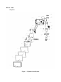
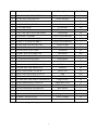
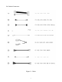
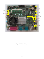
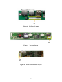
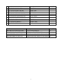
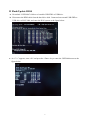
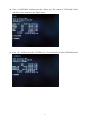
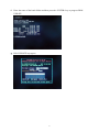
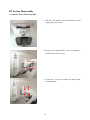
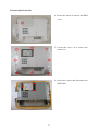
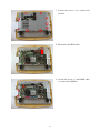
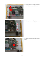
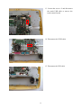
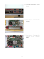
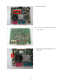
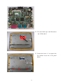
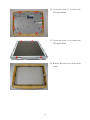
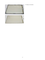
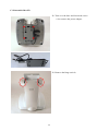
Service Manual
Zenis POS Series
Version 1.0
© Copyright Fametech Inc. (TYSSO) 2010
i
Table of Contents
I Part List..... ................................................................................................................................... 1 A. Explode................................................................................................................................ 1 B. Cables & Connectors ........................................................................................................... 3 II Flash/Update BIOS .................................................................................................................... 7 III System Disassembly ................................................................................................................ 10 A. Separate Front Panel from Base ........................................................................................ 10 B. Disassemble Panel Kit ....................................................................................................... 11 Table of Figures
Figure 1
Figure 2
Figure 3
Figure 4
Figure 5
Figure 6
Explode of the System .................................................................................. 1 Cables ............................................................................................................ 3 Mainboard Layout ....................................................................................... 4 I/O Board Layout ......................................................................................... 5 Inverter Layout ............................................................................................. 5 Touch Control Board Layout ...................................................................... 5 ii
I Part List
A. Explode
Figure 1
Explode of the System
1
No.
Part No.
Description
Price(USD)
Front Cover(White)
12
Power Indicator
1
Touch Panel Rubber
3
Inverter
12
1
JP-POS-3000-FRONT-COVER-W
2
CP-CBL-POS-7000-LED-PW
3
JP-POS-5050-RUBBER
4
BP-PART-CUBIC-QF117V1
5
LC-LG-LM150X08
LCD Panel
156
6
KP-POS-5700-LCD
LCD Panel Chassis
10
7
LT-HT-150F-5RA-G01N-18R-200FH
Touch Panel
50
8
KP-POS-8015-10-BRKT
Power Switch Bracket
3
9
NS-POS-5000-HIT-4028-82280
Speakers
5
10 KP-POS-5715-PWR-SW-BRKT
Power Switch Bracket
3
11 CP-CBL-POS-5700-SW-B15CM
Power Switch
2
Touch Control Board
20
13 BP-PCBA-POS-5700-CONN
PS2 Board
10
14 BP-PART-POS-3000-MB-PCBA
Mainboard
200
15 KP-POS-5715-MB-COVER
Mainboard Cover
8
16 KP-POS-6000-HD-HOLDER
HDD Holder
2
17 BP-PART-SATA-2.5HDD-80G-5400
HDD
70
18 JP-POS-3000-MSR-RIGHT-Cover-W
MSR Cover
1
18-1 BP-SEMI-POS-3000-MSR-KP-W
MSR Kit
40
19 JP-POS-3000-REAR-COVER-W
Rear Cover
15
Plug
0.20
HDD Cover
3
Hinge Holder
10
Hinge Rear Cover
2
Aluminum Base
30
24 KP-POS-3000-BASE-HOLDER-W
Base Holder
3
25 JP-POS-3000-BASE-COVER-W
Base Cover
3
26 JP-POS-3000-HINGE-SWIVEL-W
Hinge Swivel
3
27 DP-PWRC-EA11003A-ED
Power Adapter
35
28 KP-POS-3000-PWR-BRKT
Power Adapter Holder
6
12 BP-PART-THPCBA-COMBO-R5W-3100C
*19-1 JP-POS-3000-ANTENNA-PLUG-W
20 JP-POS-3000-HD-COVER-W
21 BP-SEMI-POS-3000-HINGE-HOLDER-W
22 JP-POS-3000-HINGE-COVER-W
23 KP-POS-3000-BASE-W
* If the antenna is equipped, the plug will not be included in the system.
2
B. Cables & Connectors
Figure 2
3
Cables
c
i
d
j
g
k
e
f
h
Figure 3
Mainboard Layout
4
k
Figure 4
I/O Board Layout
j
Figure 5
Inverter Layout
d
Figure 6 Touch Control Board Layout
5
No. Part No.
Description
Price(USD)
1
CP-CBL-POS-SATA-HDD
HDD Cable
5
2
CP-CBL-POS-5000-TH-USB
Touch Cable
2
3
CP-CBL-POS-5700-LVDS-B24cm
LVDS Cable
4
4
CP-CBL-POS-5700FS-LED-PW
Power Indicator
1
5
CP-CBL-POS-5700-SW-B15CM
Power Switch
2
6
NS-POS-5000-HIT-4028-82280
Speakers
5
7
CP-CBL-POS-5700-MMSR-B17cm
MSR Cable
3
8
CP-CBL-POS-7000-INT
Inverter Cable
2
9
CP-CBL-POS-5700-MB-IO-B10
I/O Board Cable
2
Part No.
Description
Price(USD)
BP-PART-POS-5000-HEATSINK
CPU heat dissipation fin
15
BP-PART-SYS –FAN-DFB500912M
POS System Fan DFB500912M
5
BP-PART-DDR2-667/800-1GB
DDRII RAM 1GB, DDR2-667/800 200Pin
35
BP-PART-DDR2-667/800-2GB
DDRII RAM 2GB, DDR2-667/800 200Pin
60
6
II Flash/Update BIOS
a. Download “GSE30406” folder to a bootable USB-FDD or USB drive.
b. Disconnect the HDD cable from the hard drive disk. Connected an external USB-FDD or
USB drive to POS-3000, and enter the DOS system as the figure below.
c. As “C:\>” appears, enter “dir” and press the <Enter> key to enter the GSE30406 menu as the
figure below.
7
d. Enter “cd GSE30406” and then press the <Enter> key. The content of “GSE30406” folder
will show on the monitor as the figure below.
e. Enter “dir” and then press the <ENTER> key. View the batch file in the GSE30486 folder.
8
f.
Enter the name of the batch folder and then press the <ENTER> key to progress BIOS
UPDATE.
g. BIOS UPDATE in progress
9
III System Disassembly
A. Separate Front Panel from Base
1. Tilt the LCD panel to the horizontal level and
unplug the power cord.
2. Remove the hinge holder covers according to
the direction of the arrows.
3. Lossen the 5 screws to remove the base holder
from the panel
10
B. Disassemble Panel Kit
4. Loosen the screw to remove the HDD
cover.
5. Loosen the screw x 8 to remove the
back cover.
6. Loosen the spacer and disconnect the
HDD cable.
11
7. Loosen the screw x 9 to remove the
bracket.
8. Disconnect the HDD cable.
9. Loosen the screw x 2 and MSR cable
to remove the MSR kit.
12
10. Loosen the screw x 2 and disconnect
the 3 cables to remove the invertor.
11. Loosen the screw x 2 and disconnect
the cable to remove the SW plate.
12. Pull the hooks to remove the Connect
board
13
13. Loosen the screw x 2 and disconnect
the touch USB cable to remove the
touch control board.
14. Disconnect the LVDS cable.
15. Disconnect the LED cable
14
16. Loosen the spacer x 10 on the I/O
bracket.
17. Loosen the screw x 8 to remove the
speakers.
18. Loosen the screw x 5 to remove the
mainboard from the LCD panel
holder.
15
19. Remove the RAM.
20. Turn over the mainboard and loose
the 5 screws
21. Remove the fan cable and remove the
heat sink.
16
22. Tear the black tape and disconnect
the LVDS cable.3
23. Loosen the screw x 3 to remove the
I/O bracket from the LCD panel
holder.
17
24. Loosen the screw x 7 to remove the
LCD panel holder.
25. Loosen the screw x 4 to remove the
LCD panel holder.
26. Remove the front cover of the touch
panel.
18
27. Remove the rubber.
19
C. Disassemble Base Kit
28. Turn over the base and loosen the screw
x 4 to remove the power adaptor.
29. Remove the hinge swivels.
20
30. Loosen the screw x 8 on both sides to
remove the hinge holder.
21