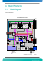
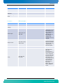
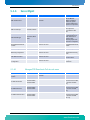
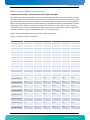
1
» Kontron User's Guide «
AT8060
Document Revision 1.2
October 2013
If it's embedded, it's Kontron.
Revision History
Rev. Index
Brief Description of Changes
Date of Issue
1.0
First Release
April 2012
1.1
Add Web interface section in charter 4.3
June 2012
1.2
Add new memory installation instructions section 3.3.2
October 2013
Customer Service
Contact Information:
Kontron Canada, Inc.
4555 Ambroise-Lafortune
Boisbriand, Québec, Canada
J7H 0A4
Tel: (450) 437-5682
(800) 354-4223
Fax: (450) 437-8053
E-mail: [email protected]
Kontron Modular Computer GMBH
Sudetenstrasse 7
87600 Kaufbeuren
Germany
+49 (0) 8341 803 333
+49 (0) 8341 803 339
[email protected]
Visit our site at: www.kontron.com
© 2011 Kontron, an International Corporation. All rights reserved.
The information in this user's guide is provided for reference only. Kontron does not assume any liability
arising out of the application or use of the information or products described herein. This user's guide may
contain or reference information and products protected by copyrights or patents and does not convey any
license under the patent rights of Kontron, nor the rights of others.
Kontron is a registered trademark of Kontron. All trademarks, registered trademarks, and trade names used
in this user's guide are the property of their respective owners. All rights reserved. Printed in Canada. This
user's guide contains information proprietary to Kontron. Customers may reprint and use this user's guide in
other publications. Customers may alter this user's guide and publish it only after they remove the Kontron
name, cover, and logo.
Kontron reserves the right to make changes without notice in product or component design as warranted by
evolution in user needs or progress in engineering or manufacturing technology. Changes that affect the
operation of the unit will be documented in the next revision of this user's guide.
i
AT8060
www.kontron.com
Table of Contents
Table of Contents
Safety Instructions . . . . . . . . . . . . . . . . . . . . . . . . . . . . . . . . . . . . . . . . . . . . . . . . . . . . . . viii
Before You Begin . . . . . . . . . . . . . . . . . . . . . . . . . . . . . . . . . . . . . . . . . . . . . . . . . . . . . . . . . . . . . . viii
Preventing Electrostatic Discharge . . . . . . . . . . . . . . . . . . . . . . . . . . . . . . . . . . . . . . . . . . . . . . . . . ix
Preface . . . . . . . . . . . . . . . . . . . . . . . . . . . . . . . . . . . . . . . . . . . . . . . . . . . . . . . . . . . . . . . . . x
How to Use This Guide . . . . . . . . . . . . . . . . . . . . . . . . . . . . . . . . . . . . . . . . . . . . . . . . . . . . . . . . . . . .x
Customer Comments . . . . . . . . . . . . . . . . . . . . . . . . . . . . . . . . . . . . . . . . . . . . . . . . . . . . . . . . . . . . . xi
Advisory Conventions . . . . . . . . . . . . . . . . . . . . . . . . . . . . . . . . . . . . . . . . . . . . . . . . . . . . . . . . . . . . xi
Unpacking . . . . . . . . . . . . . . . . . . . . . . . . . . . . . . . . . . . . . . . . . . . . . . . . . . . . . . . . . . . . . . . . . . . . xii
Powering Up the System. . . . . . . . . . . . . . . . . . . . . . . . . . . . . . . . . . . . . . . . . . . . . . . . . . . . . . . . . xii
Adapter Cables . . . . . . . . . . . . . . . . . . . . . . . . . . . . . . . . . . . . . . . . . . . . . . . . . . . . . . . . . . . . . . . . xii
Storing Boards . . . . . . . . . . . . . . . . . . . . . . . . . . . . . . . . . . . . . . . . . . . . . . . . . . . . . . . . . . . . . . . . xii
Regulatory Compliance Statements . . . . . . . . . . . . . . . . . . . . . . . . . . . . . . . . . . . . . . . . . . . . . . . . xiii
Limited Warranty . . . . . . . . . . . . . . . . . . . . . . . . . . . . . . . . . . . . . . . . . . . . . . . . . . . . . . . . . . . . . . xiv
1.
2.
Product Description . . . . . . . . . . . . . . . . . . . . . . . . . . . . . . . . . . . . . . . . . . . . . . . . . . . . . . . 2
1.1
Product Overview . . . . . . . . . . . . . . . . . . . . . . . . . . . . . . . . . . . . . . . . . . . . . . . . . . . . . . . . . . . . . 2
1.2
What’s Included. . . . . . . . . . . . . . . . . . . . . . . . . . . . . . . . . . . . . . . . . . . . . . . . . . . . . . . . . . . . . . 2
1.3
Board Specifications . . . . . . . . . . . . . . . . . . . . . . . . . . . . . . . . . . . . . . . . . . . . . . . . . . . . . . . . . . 3
1.4
Compliance . . . . . . . . . . . . . . . . . . . . . . . . . . . . . . . . . . . . . . . . . . . . . . . . . . . . . . . . . . . . . . . . . 5
1.5
Hot-Plug Capability . . . . . . . . . . . . . . . . . . . . . . . . . . . . . . . . . . . . . . . . . . . . . . . . . . . . . . . . . . . 5
1.6
Interfacing with the Environment . . . . . . . . . . . . . . . . . . . . . . . . . . . . . . . . . . . . . . . . . . . . . . . 5
1.6.1
RTM (rear transition module) . . . . . . . . . . . . . . . . . . . . . . . . . . . . . . . . . . . . . . . . . . . . . . . .5
1.6.2
Advanced Mezzanine Card. . . . . . . . . . . . . . . . . . . . . . . . . . . . . . . . . . . . . . . . . . . . . . . . . . .6
Board Features . . . . . . . . . . . . . . . . . . . . . . . . . . . . . . . . . . . . . . . . . . . . . . . . . . . . . . . . . . . 9
2.1
Block Diagram . . . . . . . . . . . . . . . . . . . . . . . . . . . . . . . . . . . . . . . . . . . . . . . . . . . . . . . . . . . . . . . 9
2.2
System Core . . . . . . . . . . . . . . . . . . . . . . . . . . . . . . . . . . . . . . . . . . . . . . . . . . . . . . . . . . . . . . . . 10
2.2.1
Processors (SandyBridge-EP Series) . . . . . . . . . . . . . . . . . . . . . . . . . . . . . . . . . . . . . . . . . .10
2.2.2
Intel Patsburg PCH . . . . . . . . . . . . . . . . . . . . . . . . . . . . . . . . . . . . . . . . . . . . . . . . . . . . . . .10
2.3
USB 2.0 Interfaces. . . . . . . . . . . . . . . . . . . . . . . . . . . . . . . . . . . . . . . . . . . . . . . . . . . . . . . . . . . 10
2.4
USB Flash Module . . . . . . . . . . . . . . . . . . . . . . . . . . . . . . . . . . . . . . . . . . . . . . . . . . . . . . . . . . . 11
2.5
Serial ATA/Serial Attached SCSI . . . . . . . . . . . . . . . . . . . . . . . . . . . . . . . . . . . . . . . . . . . . . . . . 11
2.5.1
Serial Attached SCSI . . . . . . . . . . . . . . . . . . . . . . . . . . . . . . . . . . . . . . . . . . . . . . . . . . . . . .11
2.5.2
Serial ATA (PCH) . . . . . . . . . . . . . . . . . . . . . . . . . . . . . . . . . . . . . . . . . . . . . . . . . . . . . . . . .11
ii
AT8060
www.kontron.com
Table of Contents
2.6
Redundant BIOS Flash . . . . . . . . . . . . . . . . . . . . . . . . . . . . . . . . . . . . . . . . . . . . . . . . . . . . . . . . 12
2.7
Ethernet Interfaces . . . . . . . . . . . . . . . . . . . . . . . . . . . . . . . . . . . . . . . . . . . . . . . . . . . . . . . . . . 12
2.7.1
Fabric Interface . . . . . . . . . . . . . . . . . . . . . . . . . . . . . . . . . . . . . . . . . . . . . . . . . . . . . . . . .12
2.7.2
Base Interface . . . . . . . . . . . . . . . . . . . . . . . . . . . . . . . . . . . . . . . . . . . . . . . . . . . . . . . . . .12
2.7.3
SFP . . . . . . . . . . . . . . . . . . . . . . . . . . . . . . . . . . . . . . . . . . . . . . . . . . . . . . . . . . . . . . . . . . .13
2.8
Serial Interfaces . . . . . . . . . . . . . . . . . . . . . . . . . . . . . . . . . . . . . . . . . . . . . . . . . . . . . . . . . . . . 14
2.9
AMC Mezzanine . . . . . . . . . . . . . . . . . . . . . . . . . . . . . . . . . . . . . . . . . . . . . . . . . . . . . . . . . . . . . 14
2.10 FPGA . . . . . . . . . . . . . . . . . . . . . . . . . . . . . . . . . . . . . . . . . . . . . . . . . . . . . . . . . . . . . . . . . . . . . . 15
2.11 Redundant IPMC Firmware & BootBlock . . . . . . . . . . . . . . . . . . . . . . . . . . . . . . . . . . . . . . . . . . 16
2.12 LEDs Description . . . . . . . . . . . . . . . . . . . . . . . . . . . . . . . . . . . . . . . . . . . . . . . . . . . . . . . . . . . . 16
3.
2.12.1
Hot Swap LED (LED0) . . . . . . . . . . . . . . . . . . . . . . . . . . . . . . . . . . . . . . . . . . . . . . . . . . . . .16
2.12.2
Out Of Service (LED1) . . . . . . . . . . . . . . . . . . . . . . . . . . . . . . . . . . . . . . . . . . . . . . . . . . . . .17
2.12.3
Healthy LED (LED2). . . . . . . . . . . . . . . . . . . . . . . . . . . . . . . . . . . . . . . . . . . . . . . . . . . . . . .17
Installing the Board. . . . . . . . . . . . . . . . . . . . . . . . . . . . . . . . . . . . . . . . . . . . . . . . . . . . . . 20
3.1
4.
Setting Jumpers . . . . . . . . . . . . . . . . . . . . . . . . . . . . . . . . . . . . . . . . . . . . . . . . . . . . . . . . . . . . 20
3.1.1
Jumper Description . . . . . . . . . . . . . . . . . . . . . . . . . . . . . . . . . . . . . . . . . . . . . . . . . . . . . .20
3.1.2
Jumper Setting & Locations . . . . . . . . . . . . . . . . . . . . . . . . . . . . . . . . . . . . . . . . . . . . . . . .21
3.2
Processor . . . . . . . . . . . . . . . . . . . . . . . . . . . . . . . . . . . . . . . . . . . . . . . . . . . . . . . . . . . . . . . . . . 21
3.3
Memory . . . . . . . . . . . . . . . . . . . . . . . . . . . . . . . . . . . . . . . . . . . . . . . . . . . . . . . . . . . . . . . . . . . 21
3.3.1
Memory List and Characteristics . . . . . . . . . . . . . . . . . . . . . . . . . . . . . . . . . . . . . . . . . . . . .22
3.3.2
Installing Memory . . . . . . . . . . . . . . . . . . . . . . . . . . . . . . . . . . . . . . . . . . . . . . . . . . . . . . .23
3.4
Onboard Connectors and Headers . . . . . . . . . . . . . . . . . . . . . . . . . . . . . . . . . . . . . . . . . . . . . . . 24
3.5
Board Hot Swap and Installation . . . . . . . . . . . . . . . . . . . . . . . . . . . . . . . . . . . . . . . . . . . . . . . 25
3.5.1
Installing the Board in the Chassis. . . . . . . . . . . . . . . . . . . . . . . . . . . . . . . . . . . . . . . . . . .25
3.5.2
Removing the Board . . . . . . . . . . . . . . . . . . . . . . . . . . . . . . . . . . . . . . . . . . . . . . . . . . . . . .25
3.5.3
Installing an AMC . . . . . . . . . . . . . . . . . . . . . . . . . . . . . . . . . . . . . . . . . . . . . . . . . . . . . . . .26
3.5.4
Removing an AMC . . . . . . . . . . . . . . . . . . . . . . . . . . . . . . . . . . . . . . . . . . . . . . . . . . . . . . . .26
3.5.5
Installing the (RTM806X or RTM8050) . . . . . . . . . . . . . . . . . . . . . . . . . . . . . . . . . . . . . . . .26
3.5.6
Removing the (RTM806X or RTM8050) . . . . . . . . . . . . . . . . . . . . . . . . . . . . . . . . . . . . . . . .26
Management . . . . . . . . . . . . . . . . . . . . . . . . . . . . . . . . . . . . . . . . . . . . . . . . . . . . . . . . . . . 28
4.1
Hardware Management Overview . . . . . . . . . . . . . . . . . . . . . . . . . . . . . . . . . . . . . . . . . . . . . . . 28
4.2
Configuring LAN interface. . . . . . . . . . . . . . . . . . . . . . . . . . . . . . . . . . . . . . . . . . . . . . . . . . . . . 28
iii
AT8060
www.kontron.com
Table of Contents
4.3
Web Management Interface . . . . . . . . . . . . . . . . . . . . . . . . . . . . . . . . . . . . . . . . . . . . . . . . . . . 28
4.3.1
Connecting to the Web Management Interface . . . . . . . . . . . . . . . . . . . . . . . . . . . . . . . . . .28
4.3.2
System . . . . . . . . . . . . . . . . . . . . . . . . . . . . . . . . . . . . . . . . . . . . . . . . . . . . . . . . . . . . . . . .29
4.3.3
Sensor . . . . . . . . . . . . . . . . . . . . . . . . . . . . . . . . . . . . . . . . . . . . . . . . . . . . . . . . . . . . . . . .29
4.3.4
Event Log . . . . . . . . . . . . . . . . . . . . . . . . . . . . . . . . . . . . . . . . . . . . . . . . . . . . . . . . . . . . . .29
4.3.5
Control . . . . . . . . . . . . . . . . . . . . . . . . . . . . . . . . . . . . . . . . . . . . . . . . . . . . . . . . . . . . . . . .29
4.3.6
Maintenance . . . . . . . . . . . . . . . . . . . . . . . . . . . . . . . . . . . . . . . . . . . . . . . . . . . . . . . . . . . .30
4.3.7
Logout . . . . . . . . . . . . . . . . . . . . . . . . . . . . . . . . . . . . . . . . . . . . . . . . . . . . . . . . . . . . . . . .31
4.4
Hardware Management Functionality. . . . . . . . . . . . . . . . . . . . . . . . . . . . . . . . . . . . . . . . . . . . 31
4.5
IPMC Specific Features . . . . . . . . . . . . . . . . . . . . . . . . . . . . . . . . . . . . . . . . . . . . . . . . . . . . . . . 31
4.5.1
4.6
5.
Sensors. . . . . . . . . . . . . . . . . . . . . . . . . . . . . . . . . . . . . . . . . . . . . . . . . . . . . . . . . . . . . . . .32
IPMC . . . . . . . . . . . . . . . . . . . . . . . . . . . . . . . . . . . . . . . . . . . . . . . . . . . . . . . . . . . . . . . . . . . . . . 33
4.6.1
Supported Commands. . . . . . . . . . . . . . . . . . . . . . . . . . . . . . . . . . . . . . . . . . . . . . . . . . . . .33
4.6.2
Sensor Data Records . . . . . . . . . . . . . . . . . . . . . . . . . . . . . . . . . . . . . . . . . . . . . . . . . . . . . .41
4.6.3
FRU Information . . . . . . . . . . . . . . . . . . . . . . . . . . . . . . . . . . . . . . . . . . . . . . . . . . . . . . . . .58
4.6.4
Clock E-Keying Information . . . . . . . . . . . . . . . . . . . . . . . . . . . . . . . . . . . . . . . . . . . . . . . .63
Software Setup. . . . . . . . . . . . . . . . . . . . . . . . . . . . . . . . . . . . . . . . . . . . . . . . . . . . . . . . . . 65
5.1
AMI UEFI Setup Program . . . . . . . . . . . . . . . . . . . . . . . . . . . . . . . . . . . . . . . . . . . . . . . . . . . . . . 65
5.1.1
Accessing the UEFI Setup Utility . . . . . . . . . . . . . . . . . . . . . . . . . . . . . . . . . . . . . . . . . . . . .65
5.1.2
Menu Bar . . . . . . . . . . . . . . . . . . . . . . . . . . . . . . . . . . . . . . . . . . . . . . . . . . . . . . . . . . . . . .66
5.1.3
Main Menu . . . . . . . . . . . . . . . . . . . . . . . . . . . . . . . . . . . . . . . . . . . . . . . . . . . . . . . . . . . . .68
5.1.4
Advanced Menu. . . . . . . . . . . . . . . . . . . . . . . . . . . . . . . . . . . . . . . . . . . . . . . . . . . . . . . . . .69
5.1.5
Chipset . . . . . . . . . . . . . . . . . . . . . . . . . . . . . . . . . . . . . . . . . . . . . . . . . . . . . . . . . . . . . . . .91
5.1.6
Server Mgmt . . . . . . . . . . . . . . . . . . . . . . . . . . . . . . . . . . . . . . . . . . . . . . . . . . . . . . . . . . .100
5.1.7
Boot . . . . . . . . . . . . . . . . . . . . . . . . . . . . . . . . . . . . . . . . . . . . . . . . . . . . . . . . . . . . . . . . .105
5.1.8
Security . . . . . . . . . . . . . . . . . . . . . . . . . . . . . . . . . . . . . . . . . . . . . . . . . . . . . . . . . . . . . .106
5.1.9
Save & Exit . . . . . . . . . . . . . . . . . . . . . . . . . . . . . . . . . . . . . . . . . . . . . . . . . . . . . . . . . . . .106
5.2
Boot Utilities . . . . . . . . . . . . . . . . . . . . . . . . . . . . . . . . . . . . . . . . . . . . . . . . . . . . . . . . . . . . . . 107
5.2.1
Entering BIOS Setup Menu . . . . . . . . . . . . . . . . . . . . . . . . . . . . . . . . . . . . . . . . . . . . . . . .107
5.2.2
SAS Option ROM (RTM8050) . . . . . . . . . . . . . . . . . . . . . . . . . . . . . . . . . . . . . . . . . . . . . . .107
5.2.3
SAS Option ROM (RTM806X) . . . . . . . . . . . . . . . . . . . . . . . . . . . . . . . . . . . . . . . . . . . . . . .107
5.3
Console Redirection (VT100 Mode). . . . . . . . . . . . . . . . . . . . . . . . . . . . . . . . . . . . . . . . . . . . . 108
5.3.1
Requirements . . . . . . . . . . . . . . . . . . . . . . . . . . . . . . . . . . . . . . . . . . . . . . . . . . . . . . . . . .108
5.3.2
ANSI and VT100 Keystroke Mapping . . . . . . . . . . . . . . . . . . . . . . . . . . . . . . . . . . . . . . . . .108
5.3.3
VT-UTF8 Keystroke Mapping . . . . . . . . . . . . . . . . . . . . . . . . . . . . . . . . . . . . . . . . . . . . . . .108
iv
AT8060
www.kontron.com
Table of Contents
6.
Thermal Considerations . . . . . . . . . . . . . . . . . . . . . . . . . . . . . . . . . . . . . . . . . . . . . . . . . . 111
6.1
A.
B.
Thermal Monitoring . . . . . . . . . . . . . . . . . . . . . . . . . . . . . . . . . . . . . . . . . . . . . . . . . . . . . . . . . 111
6.1.1
Heat Sinks . . . . . . . . . . . . . . . . . . . . . . . . . . . . . . . . . . . . . . . . . . . . . . . . . . . . . . . . . . . .111
6.1.2
Temperature Sensors . . . . . . . . . . . . . . . . . . . . . . . . . . . . . . . . . . . . . . . . . . . . . . . . . . . .111
6.1.3
Airflow blockers . . . . . . . . . . . . . . . . . . . . . . . . . . . . . . . . . . . . . . . . . . . . . . . . . . . . . . . .113
6.1.4
System Airflow . . . . . . . . . . . . . . . . . . . . . . . . . . . . . . . . . . . . . . . . . . . . . . . . . . . . . . . . .113
6.1.5
Thermal Profile . . . . . . . . . . . . . . . . . . . . . . . . . . . . . . . . . . . . . . . . . . . . . . . . . . . . . . . . .114
Memory & I/O Maps . . . . . . . . . . . . . . . . . . . . . . . . . . . . . . . . . . . . . . . . . . . . . . . . . . . . . .A-1
A.1
Memory Mapping . . . . . . . . . . . . . . . . . . . . . . . . . . . . . . . . . . . . . . . . . . . . . . . . . . . . . . . . . . . .A-1
A.2
Kontron I/O Mapping. . . . . . . . . . . . . . . . . . . . . . . . . . . . . . . . . . . . . . . . . . . . . . . . . . . . . . . . .A-2
A.3
PCI IDSEL and Device Numbers . . . . . . . . . . . . . . . . . . . . . . . . . . . . . . . . . . . . . . . . . . . . . . . . .A-2
Connector Pinouts . . . . . . . . . . . . . . . . . . . . . . . . . . . . . . . . . . . . . . . . . . . . . . . . . . . . . . .B-1
B.1
Connectors and Headers Summary . . . . . . . . . . . . . . . . . . . . . . . . . . . . . . . . . . . . . . . . . . . . . .B-1
B.2
Post Codes (J2) . . . . . . . . . . . . . . . . . . . . . . . . . . . . . . . . . . . . . . . . . . . . . . . . . . . . . . . . . . . . .B-1
B.3
AMC B1(J19) . . . . . . . . . . . . . . . . . . . . . . . . . . . . . . . . . . . . . . . . . . . . . . . . . . . . . . . . . . . . . . .B-2
B.4
USB Dual Port (J12) . . . . . . . . . . . . . . . . . . . . . . . . . . . . . . . . . . . . . . . . . . . . . . . . . . . . . . . . .B-3
B.5
Serial Port, COM1(J13) . . . . . . . . . . . . . . . . . . . . . . . . . . . . . . . . . . . . . . . . . . . . . . . . . . . . . .B-3
B.6
USB Flash Drive(J10, J11) . . . . . . . . . . . . . . . . . . . . . . . . . . . . . . . . . . . . . . . . . . . . . . . . . . . .B-3
B.7
Base Interface & Fabric Interface (J23) . . . . . . . . . . . . . . . . . . . . . . . . . . . . . . . . . . . . . . . . . .B-4
B.8
RTM Connector (J30) . . . . . . . . . . . . . . . . . . . . . . . . . . . . . . . . . . . . . . . . . . . . . . . . . . . . . . . .B-5
B.9
RTM Connector (J31) . . . . . . . . . . . . . . . . . . . . . . . . . . . . . . . . . . . . . . . . . . . . . . . . . . . . . . . .B-5
B.10 Power (P10). . . . . . . . . . . . . . . . . . . . . . . . . . . . . . . . . . . . . . . . . . . . . . . . . . . . . . . . . . . . . . . .B-6
C.
BIOS Setup Error Codes . . . . . . . . . . . . . . . . . . . . . . . . . . . . . . . . . . . . . . . . . . . . . . . . . . . C-1
C.1
Memory Reference Code . . . . . . . . . . . . . . . . . . . . . . . . . . . . . . . . . . . . . . . . . . . . . . . . . . . . . . C-1
C.2
SEC Status Codes . . . . . . . . . . . . . . . . . . . . . . . . . . . . . . . . . . . . . . . . . . . . . . . . . . . . . . . . . . . . C-2
C.3
PEI Status Codes . . . . . . . . . . . . . . . . . . . . . . . . . . . . . . . . . . . . . . . . . . . . . . . . . . . . . . . . . . . . C-2
C.4
DXE Status Codes . . . . . . . . . . . . . . . . . . . . . . . . . . . . . . . . . . . . . . . . . . . . . . . . . . . . . . . . . . . . C-4
C.5
ACPI/ASL Status Codes . . . . . . . . . . . . . . . . . . . . . . . . . . . . . . . . . . . . . . . . . . . . . . . . . . . . . . . C-6
D.
Software Update . . . . . . . . . . . . . . . . . . . . . . . . . . . . . . . . . . . . . . . . . . . . . . . . . . . . . . . D-1
E.
Getting Help . . . . . . . . . . . . . . . . . . . . . . . . . . . . . . . . . . . . . . . . . . . . . . . . . . . . . . . . . . . .E-1
F.
E.1
Returning Defective Merchandise. . . . . . . . . . . . . . . . . . . . . . . . . . . . . . . . . . . . . . . . . . . . . . . E-1
E.2
When Returning a Unit . . . . . . . . . . . . . . . . . . . . . . . . . . . . . . . . . . . . . . . . . . . . . . . . . . . . . . . E-2
Glossary . . . . . . . . . . . . . . . . . . . . . . . . . . . . . . . . . . . . . . . . . . . . . . . . . . . . . . . . . . . . . . . F-1
v
AT8060
www.kontron.com
List of Figures
List of Figures
Figure 2-1: Block Diagram . . . . . . . . . . . . . . . . . . . . . . . . . . . . . . . . . . . . . . . . . . . . . . . . . . . . . . . . . . . . . .9
Figure 2-2: Faceplate LEDs . . . . . . . . . . . . . . . . . . . . . . . . . . . . . . . . . . . . . . . . . . . . . . . . . . . . . . . . . . . . .18
Figure 3-1: Jumper Settings and Locations . . . . . . . . . . . . . . . . . . . . . . . . . . . . . . . . . . . . . . . . . . . . . . . .21
Figure 3-2: Onboard Connectors and Headers Locations . . . . . . . . . . . . . . . . . . . . . . . . . . . . . . . . . . . . . .24
Figure 4-1: E-Keying possibilities. . . . . . . . . . . . . . . . . . . . . . . . . . . . . . . . . . . . . . . . . . . . . . . . . . . . . . . .60
Figure 6-1: Pressure Curve in Imperial . . . . . . . . . . . . . . . . . . . . . . . . . . . . . . . . . . . . . . . . . . . . . . . . . . .113
Figure 6-2: Pressure Curve in Metric . . . . . . . . . . . . . . . . . . . . . . . . . . . . . . . . . . . . . . . . . . . . . . . . . . . . .114
Figure 6-3: CPU Thermal Profile . . . . . . . . . . . . . . . . . . . . . . . . . . . . . . . . . . . . . . . . . . . . . . . . . . . . . . . .114
vi
AT8060
www.kontron.com
List of Tables
List of Tables
Table 1-1 Board Specifications. . . . . . . . . . . . . . . . . . . . . . . . . . . . . . . . . . . . . . . . . . . . . . . . . . . . . . . . . . 3
Table 2-1 SFP LED Significations . . . . . . . . . . . . . . . . . . . . . . . . . . . . . . . . . . . . . . . . . . . . . . . . . . . . . . . 13
Table 2-2 Serial Interface connector Pinout . . . . . . . . . . . . . . . . . . . . . . . . . . . . . . . . . . . . . . . . . . . . . . . 14
Table 2-3 Faceplate LEDs. . . . . . . . . . . . . . . . . . . . . . . . . . . . . . . . . . . . . . . . . . . . . . . . . . . . . . . . . . . . . . 16
Table 3-1 Jumper Description . . . . . . . . . . . . . . . . . . . . . . . . . . . . . . . . . . . . . . . . . . . . . . . . . . . . . . . . . . 20
Table 3-2 Approved Memory List . . . . . . . . . . . . . . . . . . . . . . . . . . . . . . . . . . . . . . . . . . . . . . . . . . . . . . . 22
Table 3-3 Onboard Connectors and Headers . . . . . . . . . . . . . . . . . . . . . . . . . . . . . . . . . . . . . . . . . . . . . . . 24
Table 4-1 Privilege Level Description . . . . . . . . . . . . . . . . . . . . . . . . . . . . . . . . . . . . . . . . . . . . . . . . . . . . 30
Table 4-2 IPM Device Supported Commands for IPMC . . . . . . . . . . . . . . . . . . . . . . . . . . . . . . . . . . . . . . . . 33
Table 4-3 Watchdog Timer Supported Commands for IPMC . . . . . . . . . . . . . . . . . . . . . . . . . . . . . . . . . . . . 33
Table 4-4 Device Messaging Supported Commands for IPMC . . . . . . . . . . . . . . . . . . . . . . . . . . . . . . . . . . . 33
Table 4-5 Chassis Device Supported Commands for IPMC . . . . . . . . . . . . . . . . . . . . . . . . . . . . . . . . . . . . . 35
Table 4-6 Event Supported Commands for IPMC . . . . . . . . . . . . . . . . . . . . . . . . . . . . . . . . . . . . . . . . . . . . 35
Table 4-7 PEF and Alerting Supported Commands for IPMC . . . . . . . . . . . . . . . . . . . . . . . . . . . . . . . . . . . . 36
Table 4-8 Sensor Device Supported Commands for IPMC . . . . . . . . . . . . . . . . . . . . . . . . . . . . . . . . . . . . . . 36
Table 4-9 FRU Device Supported Commands for IPMC . . . . . . . . . . . . . . . . . . . . . . . . . . . . . . . . . . . . . . . . 37
Table 4-10 SDR Device Supported Commands for IPMC . . . . . . . . . . . . . . . . . . . . . . . . . . . . . . . . . . . . . . . 37
Table 4-11 SEL Device Supported Commands for IPMC . . . . . . . . . . . . . . . . . . . . . . . . . . . . . . . . . . . . . . . 37
Table 4-12 LAN Device Supported Commands for IPMC . . . . . . . . . . . . . . . . . . . . . . . . . . . . . . . . . . . . . . . 38
Table 4-13 Serial/Modem Device Supported Commands for IPMC . . . . . . . . . . . . . . . . . . . . . . . . . . . . . . . 38
Table 4-14 SOL Commands . . . . . . . . . . . . . . . . . . . . . . . . . . . . . . . . . . . . . . . . . . . . . . . . . . . . . . . . . . . . 39
Table 4-15 PICMG 3.0 Commands for IPMC . . . . . . . . . . . . . . . . . . . . . . . . . . . . . . . . . . . . . . . . . . . . . . . . 39
Table 4-16 AMC.0 Carrier Commands for IPMC. . . . . . . . . . . . . . . . . . . . . . . . . . . . . . . . . . . . . . . . . . . . . . 40
Table 4-17 HPM Commands . . . . . . . . . . . . . . . . . . . . . . . . . . . . . . . . . . . . . . . . . . . . . . . . . . . . . . . . . . . . 41
Table 4-18 IPMC Sensors . . . . . . . . . . . . . . . . . . . . . . . . . . . . . . . . . . . . . . . . . . . . . . . . . . . . . . . . . . . . . 42
Table 4-19
IPMC Health Indicator Sensor Aggregation Table. . . . . . . . . . . . . . . . . . . . . . . . . . . . . . . . . . 57
Table 4-20 Board Information Area. . . . . . . . . . . . . . . . . . . . . . . . . . . . . . . . . . . . . . . . . . . . . . . . . . . . . . 58
Table 4-21 Product Information Area . . . . . . . . . . . . . . . . . . . . . . . . . . . . . . . . . . . . . . . . . . . . . . . . . . . . 59
Table 4-22 E-Keying capabilities of the board . . . . . . . . . . . . . . . . . . . . . . . . . . . . . . . . . . . . . . . . . . . . . 61
Table 4-23 AMC Carrier Activation and Carrier Information Table . . . . . . . . . . . . . . . . . . . . . . . . . . . . . . . 62
Table 4-24 Carrier AMC.0 . . . . . . . . . . . . . . . . . . . . . . . . . . . . . . . . . . . . . . . . . . . . . . . . . . . . . . . . . . . . . 63
Table 6-1 Temperature Sensors Thresholds . . . . . . . . . . . . . . . . . . . . . . . . . . . . . . . . . . . . . . . . . . . . . . . 112
Table 6-2 Pressure curve AT8060 with AM4320 in bay AMC . . . . . . . . . . . . . . . . . . . . . . . . . . . . . . . . . . . 113
vii
AT8060
www.kontron.com
Safety Instructions
Safety Instructions
Before You Begin
Before handling the board, read the instructions and safety guidelines on the following pages to prevent
damage to the product and to ensure your own personal safety. Refer to the "Advisories" section in the
Preface for advisory conventions used in this user's guide, including the distinction between Warnings,
Cautions, Important Notes, and Notes.
• Always use caution when handling/operating the computer. Only qualified, experienced,
authorized electronics service personnel should access the interior of the computer. The power
supplies produce high voltages and energy hazards, which can cause bodily harm.
• Use extreme caution when installing or removing components. Refer to the installation
instructions in this user's guide for precautions and procedures. If you have any questions, please
contact Kontron Technical Support
WARNING
High voltages are present inside the chassis when the unit's power cord is plugged
into an electrical outlet. Turn off system power, turn off the power supply, and then
disconnect the power cord from its source before removing the chassis cover. Turning
off the system power switch does not remove power to components.
viii
AT8060
www.kontron.com
Safety Instructions
Preventing Electrostatic Discharge
Static electricity can harm system boards. Perform service at an ESD workstation and follow proper ESD
procedure to reduce the risk of damage to components. Kontron strongly encourages you to follow proper
ESD procedure, which can include wrist straps and smocks, when servicing equipment.
Take the following steps to prevent damage from electrostatic discharge (ESD):
•When unpacking a static-sensitive component from its shipping carton, do not remove the
component's antistatic packing material until you are ready to install the component in a
computer. Just before unwrapping the antistatic packaging, be sure you are at an ESD workstation
or grounded. This will discharge any static electricity that may have built up in your body.
•When transporting a sensitive component, first place it in an antistatic container or packaging.
•Handle all sensitive components at an ESD workstation. If possible, use antistatic floor pads and
workbench pads.
•Handle components and boards with care. Don't touch the components or contacts on a board. Hold
a board by its edges or by its metal mounting bracket.
•Do not handle or store system boards near strong electrostatic, electromagnetic, magnetic, or
radioactive fields.
•When you want to remove the protective foil (if present), make sure you are properly grounded and
that you touch a metalic part of the board.
CAUTION
Removing the protective foil from the top and bottom cover might create static.
When you remove those protections, make sure you follow the proper ESD procedure.
ix
AT8060
www.kontron.com
Preface
Preface
How to Use This Guide
This user's guide is designed to be used as step-by-step instructions for installation, and as a reference for
operation, troubleshooting, and upgrades.
For the circuits, descriptions and tables indicated, Kontron assumes no responsibility as far as patents or
other rights of third parties are concerned.
The following is a summary of chapter contents:
•Chapter 1, Product Description
•Chapter 2, Board Features
•Chapter 3, Installing the board
•Chapter 4, Hardware Management
•Chapter 5, Software Setup
•Chapter 6, Thermal Considerations
•Appendix A, Memory & I/O Maps
•Appendix B, Connector Pinout
•Appendix C, BIOS Setup Error Codes
•Appendix D, Software Update
•Appendix E, Getting Help
•Appendix F, Glossary
x
AT8060
www.kontron.com
Preface
Customer Comments
If you have any difficulties using this user's guide, discover an error, or just want to provide some feedback,
please send a message to: [email protected]. Detail any errors you find. We will correct the errors
or problems as soon as possible and post the revised user's guide on our Web site. Thank you.
Advisory Conventions
Seven types of advisories are used throughout the user guides to provide helpful information or to alert you
to the potential for hardware damage or personal injury. They are Note, Signal Paths, Jumpers Settings, BIOS
Settings, Software Usage, Cautions, and Warnings. The following is an example of each type of advisory. Use
caution when servicing electrical components.
Note:
Indicate information that is important for you to know.
Signal Path:
Indicate the places where you can find the signal on the board.
Jumper Settings:
Indicate the jumpers that are related to this section.
BIOS Settings:
Indicate where you can set this option in the BIOS.
Software Usage:
Indicates how you can access this feature through software.
CAUTION
Indicate potential damage to hardware and tells you how to avoid the problem.
WARNING
Indicates potential for bodily harm and tells you how to avoid the problem.
ESD Sensitive Device:
This symbol and title inform that electronic boards and their components are sensitive to static
electricity. Therefore, care must be taken during all handling operations and inspections of this
product, in order to ensure product integrity at all times.
Please read also the section "Special Handling and Unpacking Instructions".
CE Conformity:
This symbol indicates that the product described in this manual is in compliance with all applied CE
standards. Please refer also to the section "Regulatory Compliance Statements" in this manual.
Disclaimer: We have tried to identify all situations that may pose a warning or a caution condition in this
user's guide. However, Kontron does not claim to have covered all situations that might require the use of a
Caution or a Warning.
xi
AT8060
www.kontron.com
Preface
Unpacking
Follow these recommendations while unpacking:
•Remove all items from the box. If any items listed on the purchase order are missing, notify Kontron
customer service immediately.
•Inspect the product for damage. If there is damage, notify Kontron customer service immediately.
•Save the box and packing material for possible future shipment.
Powering Up the System
Before any installation or setup, ensure that the board is unplugged from power sources or subsystems.
If you encounter a problem, verify the following items:
•Make sure that all connectors are properly connected.
•Verify your boot devices.
•If the system does not start properly, try booting without any other I/O peripherals attached,
including AMC adapters.
Make sure your system provides the minimum DC voltages required at the board's slot, especially if DC power
is carried by cables.
If you are still not able to get your board running, contact our Technical Support for assistance.
Adapter Cables
Because adapter cables come from various manufacturers, pinouts can differ. All cables are available from
Kontron Sales Department.
Storing Boards
Electronic boards are sensitive devices. Do not handle or store device near strong electrostatic,
electromagnetic, magnetic or radioactive fields.
xii
AT8060
www.kontron.com
Preface
Regulatory Compliance Statements
FCC Compliance Statement for Class B Devices
This equipment has been tested and found to comply with the limits for a Class B digital device,
pursuant to Part 15 of the FCC Rules. These limits are designed to provide reasonable protection
against harmful interference in a residential installation. This equipment generated, uses and can
radiate radio frequency energy and, if not installed and used in accordance with the instructions
may cause harmful interference to radio communications. However, there is no guarantee that
interference will not occur in a particular installation. If this equipment does cause harmful
interference to radio or television reception, which can be determined by turning the equipment
off and on, the user is encouraged to try to correct the interference by one or more of the following
measures:
•Reorient or relocate the receiving antenna.
•Increase the separation between the equipment and receiver.
•Connect the equipment into an outlet on a circuit different from that to which the receiver is
connected.
•Consult the dealer or an experience radio/TV technician for help.
WARNING
This is a Class B product. If not installed in a properly shielded enclosure and used in
accordance with this User's Guide, this product may cause radio interference in
which case users may need to take additional measures at their own expense.
Safety Certification
All Kontron equipment meets or exceeds safety requirements based on the IEC/EN/UL/CSA 609501 family of standards entitled, "Safety of information technology equipment." All components are
chosen to reduce fire hazards and provide insulation and protection where necessary. Testing and
reports when required are performed under the international IECEE CB Scheme. Please consult the
"Kontron Safety Conformity Policy Guide" for more information. For Canada and USA input voltage
must not exceed -60Vdc for safety compliance.
CE Certification
The product(s) described in this user's guide complies with all applicable European Union (CE)
directives if it has a CE marking. For computer systems to remain CE compliant, only CE-compliant
parts may be used. Maintaining CE compliance also requires proper cable and cabling techniques.
Although Kontron offers accessories, the customer must ensure that these products are installed
with proper shielding to maintain CE compliance. Kontron does not offer engineering services for
designing cabling systems. In addition, Kontron will not retest or recertify systems or components
that have been reconfigured by customers.
xiii
AT8060
www.kontron.com
Preface
Limited Warranty
Kontron grants the original purchaser of Kontron's products a TWO YEAR LIMITED HARDWARE WARRANTY as
described in the following. However, no other warranties that may be granted or implied by anyone on behalf
of Kontron are valid unless the consumer has the express written consent of Kontron.
Kontron warrants their own products, excluding software, to be free from manufacturing and material
defects for a period of 24 consecutive months from the date of purchase. This warranty is not transferable nor
extendible to cover any other users or long- term storage of the product. It does not cover products which
have been modified, altered or repaired by any other party than Kontron or their authorized agents.
Furthermore, any product which has been, or is suspected of being damaged as a result of negligence,
improper use, incorrect handling, servicing or maintenance, or which has been damaged as a result of
excessive current/voltage or temperature, or which has had its serial number(s), any other markings or parts
thereof altered, defaced or removed will also be excluded from this warranty.
If the customer's eligibility for warranty has not been voided, in the event of any claim, he may return the
product at the earliest possible convenience to the original place of purchase, together with a copy of the
original document of purchase, a full description of the application the product is used on and a description
of the defect. Pack the product in such a way as to ensure safe transportation (see our safety instructions).
Kontron provides for repair or replacement of any part, assembly or sub-assembly at their own discretion, or
to refund the original cost of purchase, if appropriate. In the event of repair, refunding or replacement of
any part, the ownership of the removed or replaced parts reverts to Kontron, and the remaining part of the
original guarantee, or any new guarantee to cover the repaired or replaced items, will be transferred to cover
the new or repaired items. Any extensions to the original guarantee are considered gestures of goodwill, and
will be defined in the "Repair Report" issued by Kontron with the repaired or replaced item.
Kontron will not accept liability for any further claims resulting directly or indirectly from any warranty
claim, other than the above specified repair, replacement or refunding. In particular, all claims for damage
to any system or process in which the product was employed, or any loss incurred as a result of the product
not functioning at any given time, are excluded. The extent of Kontron liability to the customer shall not
exceed the original purchase price of the item for which the claim exists.
Kontron issues no warranty or representation, either explicit or implicit, with respect to its products
reliability, fitness, quality, marketability or ability to fulfil any particular application or purpose. As a result,
the products are sold "as is," and the responsibility to ensure their suitability for any given task remains that
of the purchaser. In no event will Kontron be liable for direct, indirect or consequential damages resulting
from the use of our hardware or software products, or documentation, even if Kontron were advised of the
possibility of such claims prior to the purchase of the product or during any period since the date of its
purchase.
Please remember that no Kontron employee, dealer or agent is authorized to make any modification or
addition to the above specified terms, either verbally or in any other form, written or electronically
transmitted, without the company's consent.
xiv
AT8060
www.kontron.com
Chapter 1
Product Description
1.1
1.2
1.3
1.4
1.5
1.6
Product Overview .............................................. 2
What’s Included ................................................ 2
Board Specifications .......................................... 3
Compliance ...................................................... 5
Hot-Plug Capability............................................ 5
Interfacing with the Environment ......................... 5
1
AT8060
www.kontron.com
Product Description
1. Product Description
1.1
Product Overview
The AT8060 is a single width ATCA compliant processor blade. It implements Intel’s next generation Xeon
dual processors codename Sandybridge on Romley platform. The AT8060 uses the full bandwidth of the four
DDR3 memory channels with 4 VLP DDR3 Sockets per CPU. High speed interfaces such as dual 10GBase-KX4 in
the fabric interface can deliver maximum performance using the PCIe ports from the processors. Dual 8GT/s
QPI interfaces between both CPUs provide 40GByte/s/direction for a minimum latency on memory access and
CPU process.
The chipset, the Patsburg-B, is connected to the processors via a DMI2 interface and to various I/O
components.
Three Ethernet controllers from Intel are implemented to provide high speed interfaces in the fabric
interface (82599), the base interface (82576) and on both Board and RTM faceplates (Powerville).
Additional I/O interfaces can be added with RTM and AMC cards using the x8 PCIe Gen2 provided for each. 4
SAS2 interfaces are connected to RTM interace from the PCH for storage. The AT8060 operates in two power
level modes, a regular power mode up to 225W for NEBS-like operation and a High Power mode up to 350W
for higher-class chassis applications.
1.2
What’s Included
This board is shipped with the following items:
• One AT8060 board
• One RJ45-DB9 serial adaptor (1015-9404)
• One AMC filler panel
If any item is missing or damaged, contact the supplier.
2
AT8060
www.kontron.com
Product Description
1.3
Board Specifications
Table 1-1: Board Specifications
Features
Description
Processors
•
•
•
•
Dual socket Intel Xeon Processors from the SandyBridge-EP series E5-2600 processor family.
8cores 1.8GHz 70W
8cores 2.0GHz 95W
6cores 2.3GHz 95W
Chipset
•
Patsburg-B C600 Series
Bus Interface
•
•
Dual QPI 8GT/s between both CPUs
DMI Gen2 5GT/s from CPU to Chipset
Expansion Slot
•
•
1 Mid-size AdvancedMC bay with PCIe x8 Gen 2 connection
PCIe x8 Gen2 connection to RTM
•
•
•
•
Support of DDR3 1066 to 1600MHz with ECC
Standard voltage(1.5V) and low-voltage(1.35V) modules are supported
4 memory channnels per CPU with a single DIMM location per channel
Up to 8GB memory modules per socket for a total of 64GB (note: 16GB modules could be
supported in a near future for a total of 128G)
Flash Memory
•
Two connectors for two optional eUSB (embedded USB) flash drive modules
Storage
•
•
Single SATA GEN1 (1.5Gb/s), GEN2 (3Gb/s) and GEN3 (6Gb/s) on the AMC storage interface.
Four SATA GEN1 (1.5Gb/s), GEN2 (3Gb/s), GEN3 (6Gb/s) and SAS 3Gb/s storage interfaces on
the RTM.
I/O
•
•
•
•
•
Dual SFP
Dual USB
RJ45 Serial Port
TPM mezzanine
Video debug port available on the RTM
Board Specifications
•
•
•
•
•
•
•
•
PICMG3.0 R3.0(AdvancedTCA Base Specification)
PICMG3.1 R1.0 (Ethernet/Fiber Channel over AdvancedTCA)
AMC.0 R2.0 (Advanced Mezzanine Card Base Specification)
AMC.1 R2.0 types 1, 2, 4, 8 (Advanced Mezzanine Card PCI-Express)
AMC.3 R1.0 (Advanced Mezzanine Card Storage)
ACPI rev 2.0
HPM.1
IPMI 2.0
•
AMI UEFI with Compatibility Support Module for legacy option ROMs and Operating System
support
Save BIOS Configuration to SPI.
Boot from Ethernet PXE (Base and Fabric interfaces and management Lan)
Boot from Ethernet iSCSI (Fabric interfaces)
Boot from SAS/SATA; and boot from USB 2.0 (Floppy, CD-ROM, Hard Disk)
Diskless, Keyboard less, and battery less operation extensions
System, video and LAN BIOS shadowing
Robust BIOS flash Update with rollover capability (HPM.1)
Field updateable BIOS
Advanced Configuration and Power Interface (ACPI 2.0, 3.0 & 4.0)
Console redirection to serial port (VT100)with CMOS setup access, and SOL (Serial over LAN)
Event (correctable/uncorrectable ECC,PCIe, POST errors); log support to IPMC
System Memory
BIOS Features
•
•
•
•
•
•
•
•
•
•
•
3
AT8060
www.kontron.com
Product Description
Features
Description
•
•
•
•
IPMI Features
•
•
•
•
•
•
Supervisory
•
•
•
Management Controller compliant IPMI v2.0.
Remote control capability (power on-off /clean shutdown/cold reset) via any IPMI channels
including LAN.
Full speed 115200 bps Serial Over LAN (+LAN access to BIOS menu setup) and IPMI Over LAN
(IPMI v2.0) always available.
Serial data caching and replay to ease software application troubleshooting and post mortem
analysis.
Bios Post Code errors are sent to the chassis manager's for System Event Logging.
Configurable automatic “clean ACPI shutdown” policy on disk storage deactivation (AMC or
RTM).
Standard PCIe Hot Plug operation embedded with PICMG AMC/RTM activation.
Robust IPMI firmware Update with rollover capability, without any payload impact (HPM.1).
Override configuration for activation of the board/AMC/RTM without Shelf Manager
Intervention.
Supports a system management interface (KCS interrupt driven) via an IPMI V2.0 compliant
controller.
Standard IPMI Watchdog for all CPU running phases (BIOS execution / OS loading and running).
IPMI Hardware system monitor (power/voltages), memory and all critical component's is
monitored.
Extensive sensor monitoring (around 100 IPMI sensors) and event generation based on
thresholds and discrete readings.
OS Compatibility
•
Validated with: Red Hat Enterprise Linux 5.5 and 6.1.
Power Requirements
1- NEBS power mode: =<235W (210W front board and AMC + 25W RTM)
2- High power mode: =< 350W
Environmental
Temperature*
Operating: 0-55°C/32-131°F with 30CFM airflow
Storage and Transit: -40 to +70°C/-40 to 158°F
Environmental
Humidity*
Operating: 15% to 90% @55°C/131°F non-condensing
Storage and Transit: 5% to 95% @ 40°C/104°F non-condensing
Environmental Altitude*
Operating: 4,000 m / 13,123 ft
Storage and Transit: 15,000 m / 49,212 ft
Environmental Shock*
Operating: 3G each axis
Storage and Transit: 18G each axis
Environmental
Vibration*
Operating: 5-200Hz. 0.2G, each axis
Storage and Transit: 5Hz to 20Hz @ 1 m2/s3 (0.01g2 /Hz) (flat)
20Hz to 200Hz @ -3dB/oct (slope down)
Reliability
•
•
Safety / EMC
Meet or exceed:
•
Safety: UL 60950-1; CSA C22.2 No 60950-1-03; EN 60950-1:2001; IEC60950-1
•
EMI/EMC: FCC 47 CFR Part 15, Class B; CE Mark to EN55022/EN55024/EN300386
Warranty
Two years limited warranty
Whole board protected by active breaker
USB voltage protected by active breaker
* Designed to meet or exceed
4
AT8060
www.kontron.com
Product Description
1.4
Compliance
This product conforms to the following specifications:
• PICMG3.0 R3.0(AdvancedTCA Base Specification)
• PICMG3.1 R1.0 Option 1 and 9(Ethernet/Fiber Channel over AdvancedTCA)
• AMC.0 R2.0 (Advanced Mezzanine Card Base Specification)
• AMC.1 R2.0 type 1, 2, 4 and 8 (Advanced Mezzanine Card PCI-Express)
• AMC.3 R1.0 (Advanced Mezzanine Card Storage)
• ACPI rev 2.0
• HPM.1
• IPMI 2.0
1.5
Hot-Plug Capability
The AT8060 supports Full Hot Swap capability as per PICMG3.0 R3.0 for the board itself, the RTM module and
AMC bay. It can be removed from or installed in the system while it is on (without powering-down the
system). Please refer to the PICMG3.0 R3.0 specification for additional details about Hot Swap.
The AT8060 supports PCI-Express Hotplug on AMC B1 and RTM. The IPMC uses the standard PCI Express
Hotplug Controller on the CPU board allowing hot insertion and removal of an AMC or RTM module within the
OS.
1.6
Interfacing with the Environment
1.6.1
RTM (rear transition module)
The AT8060 supports different single slot (6HP) AdvancedTCA Rear Transition Modules: RTM8050 and
RTM806X. These modules provide additional connectivity for AT8060 CPU front blade.
1.6.1.1
Standard Compliance
• PICMG3.0 R3.0 - Advanced Telecommunication Computing Architecture
1.6.1.2
Serial Port Feature
• One serial port available on the RTM face plate through a RJ-45 connector.
5
AT8060
www.kontron.com
Product Description
• RS-232 signal levels at RTM face plate connector.
• Serial port speed capability is: 9.6kbits/s to 115.2kbits/s.
1.6.1.3
Debug Video Feature
A header is present on the RTM to connect a debug video cable. This interface is suitable for low rate video,
not for HD or intensive use. Video signals are VGA standard signals. Custom video cable available on demand,
please contact Technical Support.
1.6.1.4
Hot Swap
The RTM supports hot swapping by using the switch connected to the face plate lower ejector. This switch
indicates the coming hot swap action. The insertion of the RTM to a slot is always done over a non powered
connector. During the extraction procedure, the management power is disabled only when the RTM806X is
removed. This procedure meets the AdvancedTCA AMC behavior.
1.6.1.4.1
Inserting the RTM into the slot
The presence of the RTM is indicated by one signal. The front blade IPMC recognizes the RTM insertion when
the signal is low. After recognizing the RTM, the IPMC turns the blue LED ON and enables the management
power to the RTM. Once the IPMB-L link is working, the IPMC accesses the MMC to retrieve FRU data. After
knowing the type of RTM inserted, the IPMC negotiates with the shelf manager in order to activate the +12V
payload power.
After RTM local voltages ramp up, the front board IPMC informs the shelf manager there is a functional RTM
blade present.
1.6.1.4.2
Removing the RTM from the slot
The RTM_EJECT signal goes HIGH by opening the RTM lower ejector handle. This indicates to the front blade
IPMC that a hot swap action is going to take place. The IPMC then negotiates the removal with the System
manager and if it is granted, it proceeds with the removal process.
The IPMC proceeds to the deactivation by disabling ekey governed links, the IPMC then turns OFF the payload
+12V power. When it is safe to remove the RTM blade from the slot, the IPMC turns the Blue / Hot Swap LED
ON. Front Blade IPMC turns OFF the management power only when there is no RTM detected. (RTM806X
removed from the slot)
1.6.2
Advanced Mezzanine Card
The AT8060 has one AMC bay. Using a mezzanine allows to add storage or I/O not provided on board.
1.6.2.1
AMC Expansion
The AMC slot provides an AMC.1 type 4, AMC.3 SATA. This means that the following signaling are supported:
• PCI-Express Gen2 X8 on AMC ports 4-11
6
AT8060
www.kontron.com
Product Description
• PCI-Express clock on FCLKA
• SATA on AMC port
7
AT8060
www.kontron.com
Chapter 2
Board Features
2.1
2.2
2.3
2.4
2.5
2.6
2.7
2.8
2.9
2.10
2.11
2.12
Block Diagram .................................................. 9
System Core ..................................................... 10
USB 2.0 Interfaces............................................. 10
USB Flash Module.............................................. 11
Serial ATA/Serial Attached SCSI............................ 11
Redundant BIOS Flash ........................................ 12
Ethernet Interfaces............................................ 12
Serial Interfaces................................................ 14
AMC Mezzanine ................................................. 14
FPGA............................................................... 15
Redundant IPMC Firmware & BootBlock.................. 16
LEDs Description ............................................... 16
www.kontron.com
2. Board Features
2.1
Block Diagram
Figure 2-1:Block Diagram
*6+
,
+
@/
,
"0 %
**/>*
%
**/>*
**
**
&"0 **/
/
*34/5
9;
E,<(
9;
,<(
**
&"0 **/
'"
"(
)
'"
#
B
**
/
/*
/
!"
#$%&&
*"+,)&+((-*,.
#,<(
*
2,
/
**/>*
**/>*
**/>*
#,<(
B
/
*34/5
1
B
*"+,)&+((-*,.
**
'"
"(
)
'"
#
&"0 **/
!"
#$%&&
**
/
*
/
2,
B
**
**
1
**/>*
%#
,<(
&"0 **/
**/>*
**/>*
%;
*
9#
,<(
9#
,<(
%;
*
7C>
B
*
(,<
*(
8
8
9#
,<(
,
8
*
*
@
8A "0 8
9;
E,<(
%;
2;
>
9#
,<(
%#
;4
*
=
=
'#()*++%!
!"#$
"*+'-!!
%
&
(
"0 =
@
<
/=>">
(+"
*<* F"
B6" !
;C/C
>H
**/
A"
#=
*6+
(,
,
,
,
*
"0 %E,<(
#::
*
(;19
<9
7
,
,
/
%
7
8
9+%
E
E
=
"(A6
EC,*
:
%&&
,
-&DD.
/
%
%
*34/5
,
;%
*34/5
%#
8+"
G
778,
G
"?'
G
+'
*6+
;#>
?
"
8*
8*
, ,#:F:E
9
:<<
AT8060
www.kontron.com
2.2
System Core
2.2.1
Processors (SandyBridge-EP Series)
• Built on 32 nanometer process technology.
• Six/Eight cores processor in 2011-land FCLGA.
• 32KB L1/core
• 256KB L2 / core
• Up to 20MB L3: Up to 2.5MB per core.
• Streaming SIMD Extension 4.1 and 4.2
• Integrated 4-channel DDR3 controller, DDR3-1600 memory with ECC
• Intel QuickPath interconnect links, 8.0/7.2 GT/s in each direction
• Intel 64 Bit Architecture
• Enhanced Intel SpeedStep Technology
• Intel Virtualization Technology (VT)
• Intel Hyper-Threading Technology (HT)
2.2.2
Intel Patsburg PCH
• Direct Media Interface (DMI) x4 lanes for communicating with CPU0
• SATA Gen3 up to 6Gbps, SAS Gen2 up to 3Gbps, USB
2.3
USB 2.0 Interfaces
The board embeds a USB controller in the PCH. This controller is compliant to USB 2.0. It provides two USB
ports on the face plate, two on the RTM and two ports are reserved for the eUSB SSD. Those ports can be used
for external storage and for booting.
USB supports Plug and Play and hot-swapping operations (OS level). These features allow USB devices to be
automatically attached, configured and detached, without reboot or running setup.
Signal Path:
- 2 USB 2.0 on front panel (J12, J13)
- 2 USB 2.0 on the RTM front panel
- 2 USB 2.0 onboard for the eUSB SSD
10
AT8060
www.kontron.com
BIOS Settings:
Advanced -> USB Configuration
Chipset -> South Bridge -> USB Configuration
2.4
USB Flash Module
The AT8060 supports up to two Solid State Drives. It is a NAND flash disk module with a USB 2.0 interface. The
modules are socketed on two 2x5 headers attached to the AT8060. They are available in many sizes and
accessible only when removing the top cover. By default the USB devices are used as booting devices.
Signal Path:
USB Flash Module Connector are available on J10 and J11. See section 3.4 for more details.
BIOS Settings:
Advanced --> USB Configuration
Boot --> BBS
Note:
During the installation of an OS on a HDD, the USB Flash Module must be deactivated. If the USB
Flash Module remains active, the Master Boot Record will be installed on it by default. This can not
be avoided and will cause the OS to be unable to boot from the HDD.
2.5
Serial ATA/Serial Attached SCSI
2.5.1
Serial Attached SCSI
The PCH's SAS ports 0-3 are available in the RTM connector. It supports SATA GEN1 (1.5Gb/s), GEN2 (3Gb/s),
GEN3 (6Gb/s) and SAS 3Gb/s on the RTM storage interfaces.
2.5.2
Serial ATA (PCH)
The PCH SATA port 0 is connected to the AMC Port 2. It supports SATA GEN1 (1.5Gb/s), GEN2 (3Gb/s) and
GEN3 (6Gb/s) on the AMC storage interface.
11
AT8060
www.kontron.com
2.6
Redundant BIOS Flash
Two redundant 64MBits, SPI EEPROMs are connected to PCH for the BIOS. Only one EEPROM at a time is
available for the PCH. If for some reason a BIOS update corrupts an EEPROM which prevents the CPU from
completing the boot sequence, the IPMC will swap the active SPI EEPROM and force a reboot.
2.7
Ethernet Interfaces
2.7.1
Fabric Interface
The fabric interface can be either 10GbE or 1GbE.
The AT8060 has boot from LAN capability (PXE) or iSCSI support on these ports. You can enable the option
from the BIOS Setup Program. Please refer to Section 5.1, AMI UEFI Setup Program.
The AT8060 has one dual port 10GbE controller (i82599EB) connected to the Fabric Interface. This controller
can also be used as a dual 1Gb. The controller auto-negociates between 10G-BASE-KX4 and 1G-BASE-KX.
Features high performance with TCP/IP and UDP/IP checksum offloading for IPv4 and IPv6, packet filtering,
and jumbo frame up to 15.5K.
See http://www.intel.com for additional details on the i82599EB.
Signal Path:
The two ports are available on the Fabric Interface.
BIOS Settings:
Advanced --> Legacy Expansion ROM Configuration -> FI: XE OpROM, Port 1 and 2
2.7.2
Base Interface
An i82576EB dual port 1Gb Ethernet controller is connected on the Base Interface.
Boot from LAN capability (PXE) is supported on these ports. Enable the option from the BIOS Setup Program.
Please refer to Section 5.1, AMI UEFI Setup Program.
Features high performance with TCP/IP and UDP/IP checksum offloading for IPv4 and IPv6, packet filtering,
and jumbo frame up to 16K.
See http://www.intel.com for additional details on the i82576EB.
12
AT8060
www.kontron.com
Signal Path:
The two ports are available on the Base Interface.
BIOS Settings:
Advanced --> Legacy Expansion ROM Configuration -> BI: GE OpROM, Port 1 and 2
2.7.3
SFP
A Powerville quad 1000 Base-T / SerDes controller is installed onboard. Two ports are routed to the RTM and
two are routed to the front panel SFP connectors. The front SFP cages support multi-rate fiber SFP modules.
The SFP interfaces feature the following connectivity:
• front panel with a dual SFP cage
• two connections through the RTM connector
Signal Path:
The front panel and on the RTM.
BIOS Settings:
Advanced --> Legacy Expansion ROM Configuration -> FP: GE OpROM, Port 1 and 2 (front panel)->
RTM:
CAUTION LASER LIGHT!
Do not look into the laser beam!
The SFP module is fitted with a class 1 or 1M laser. To avoid possible exposure to
hazardous levels of invisible laser radiation, do not exceed maximum ratings.
The SFP port has a bi-color green/amber LED with the following signification:
Table 2-1: SFP LED Significations
LED
Signification
Green on
Link 1Gbit
Green blink
Activity 1Gbit
Amber on
Link 10/100Mbit
Amber blink
Activity 10/100Mbit
13
AT8060
www.kontron.com
2.8
Serial Interfaces
The AT8060 uses serial interfaces to manage the CPU, the only way to get visual information from the board
when used without a RTM806X. Serial ports are provided on the faceplate and on the RTM faceplate for
asynchronous serial communications. They are 16C550 high-speed UART compatible and support 16-byte
FIFO buffers for transfer rates from 9,6Kbps to 115,2Kbps.
Table 2-2:Serial Interface connector Pinout
Pin
Signal
1
RTS
2
DTR
3
TX#
4
GND
5
GND
6
RX#
7
DSR
8
CTS
Note:
Standard product uses a RJ-45 8 pins connector. RI (ring indicator) and DCD (data carrier detect)
signals are not available.
The pinout is a custom one, not the same as RS-232D TIA/EIA-561.
Signal Path:
COM1 is routed to a RJ45 on the frontplate or to the IPMC for SOL.
COM2 is routed to the RTM serial interface.
BIOS Settings:
Advanced -> Serial Port Console Redirection -> Console Redirection Settings (COM0 and COM1)
2.9
AMC Mezzanine
The AMC slot supports AMC.1 (PCIe) and AMC.3 (SAS/SATA) in addition to the AMC.0 base specification. The
AMC is hot swappable according to PICMG 3.0 Rev. 2.0 and supports mid-size AMC units.
One AMC site is available. Characteristics of the AMC are as follow:
•Type B+
•Supports mid-size single width mechanical format
•PCI-Express X8 (GEN2 2.5GTs or 5.0GTs) with reference clock on AMC FCLKA
•Fully compliant PCI-Express hot plug support
14
AT8060
www.kontron.com
•SATA link to the PCH
•Compliant to AMC.0, AMC.1 and AMC.3
•50W maximum power budget
Note:
The thermal solution needs to be validated by the integrator when AMC Thermal Design power
exceeds 20W.
As per AMC.1 R2.0, the carrier board is required to provide PCIe 100MHz reference clock to the AMC on FCLKA.
However, modules are not required to use it. Kontron recommends using AMC modules that use the reference
clock on FCLKA. If the module makes its own reference clock, then the spread spectrum of PCI-Express clock
synthetizer will be disabled by e-keying; otherwise the behavior of the PCI-Express link will be erratic.
Note:
All electromagnetic compatibility testing has been done with spread spectrum. Disabling the spread
spectrum can complicate EMC.
The SATA interface on port 2 allows to use a SATA AMC storage mezzanine on the AT8060. AMC SATA electrical
path is properly designed for Hot Swap operation but special care must be taken to ensure proper un-mount
sequence within the operating system.
BIOS Settings:
Advanced --> SATA Configuration
Advanced --> Legacy Expansion ROM Configuration -> AMC Slot OpROM(s)
Chipset -> IOH Configuration -> AMC Port Link Speed
Server Mgmt -> Managed FRU Deactivate Policies
Software Usage:
AMC serial port is available on port 15.
AMC serial port GUID : 471C5D14-2AE7-42B9-A9B0-0628546B42CC
Note:
The maximum power budget is 50W for an Advanced Mezzanine Card.
2.10 FPGA
The FPGA has many functions. One of them is to act as a companion chip to the IPMC. The states of all the
critical signals controlled by the IPMC are memorized in the FPGA and are preserved while the IPMC firmware
is being updated.
The FPGA is a RAM-based chip that is preloaded from a separate flash memory at power-up. Two such flash
memory devices are provided; one that can only be programmed in factory and the other one that can be
updated in the field. The factory flash is selected by inserting jumper JP2 pins 3-4. Field updates require to
cycle the power of the board. The IPMI LED2 will blink amber if the factory flash is being used to signal a fail
safe configuration.
The FPGA update complies to PICMG HPM.1 specification and is remotely updatable via any IPMC channel.
15
AT8060
www.kontron.com
2.11 Redundant IPMC Firmware & BootBlock
The IPMC runs a firmware from SPI flash memory. The IPMC Boot Block saves the last two copies of the IPMC
firmware image in the same as it's boot block SPI flash memory. The Boot Block manages the IPMC
reprogrammation and can rollback to the previous firmware image in the IPMC internal flash in case of update
problem.
Note:
The IPMC has an external hardware watchdog.
2.12 LEDs Description
The following table lists the LED on the faceplate (excluding the SFP Ethernet LEDs).
Table 2-3:Faceplate LEDs
LED Name
Color
Controlled by
Description
HDD activity
Green
Chipset/FPGA
AMC & RTM HDD activity status
ATCA0
Blue
IPMC
Blade Hot Swap status
ATCA1
Amber/Red
IPMC
Blade OOS (out-of-service)
ATCA2
Amber/Green
IPMC
Healthy status
ATCA3
Amber/Green
IPMC/CPU
Application specific
B.I. 1
Amber/Green
FPGA
Base Interface Channel 1 Status
B.I. 2
Amber/Green
FPGA
Base Interface Channel 2 Status
F.I. 1
Amber/Green
FPGA
Fabric Interface Channel 1 Status
F.I. 2
Amber/Green
FPGA
Fabric Interface Channel 2 Status
RTM 1
Amber/Green
FPGA
Management LAN RTM Interface Channel
1 status
RTM 2
Amber/Green
FPGA
Management LAN RTM Interface Channel
2 status
FRONT 1
Amber/Green
FPGA
Management LAN SFP Interface Channel
1 status
FRONT 2
Amber/Green
FPGA
Management LAN SFP Interface Channel
2 status
2.12.1
Hot Swap LED (LED0)
The Blue / Hot Swap LED indicates the hot swap status of the unit. The LED is ON when it is safe to remove the
unit from the slot. During normal operation, this LED is OFF.
16
AT8060
www.kontron.com
2.12.2
Out Of Service (LED1)
The AdvancedTCA LED1 is red or amber and indicates an Out-of-Service (OOS) condition. During normal
operation, the OOS LED is OFF. This LED is ON during firmware upgrade and is user configurable if needed by a
customer application.
2.12.3
Healthy LED (LED2)
The AdvancedTCA LED2 is green or amber and indicates a healthy condition. The healthy LED indicates if the
blade is powered up and all voltages and temperatures are within specifications. During normal operation,
this LED is ON (green). This LED is also ON (amber) when one of the RTM806X voltage or temperature fails.
17
AT8060
www.kontron.com
Figure 2-2:Faceplate LEDs
Hot Swap (Blue)
Solid On
Long Blink
Solid Off
Short Blink
(100 % on):
( 90 % on):
( 0 % on):
( 10 % on):
FRU Inactive
FRU Activation Request
FRU Activation In Progress / FRU Active
FRU Deactivation Request / FRU Deactivation In Progress
Out of service (Red/Amber) [ default : Red ]
Solid On
: MMC in reset
Fast Blink (~50 % on) : MMC upgrade/rollback in progress
Application Defined : May be controlled by application using PICMG API
Health Led (Amber/Green) [ default : Green ]
Off
Green
Amber
Application Defined
:
:
:
:
Payload power down
Health Ok
Health Error (Critical)
May be controlled by application using PICMG API
Hard Disk Activity Led (Green)
Blink
: Hard Disk Activity
FI Led (Green/Amber)
Green On
Green Blink
Amber On
Amber Blink
: Link 10Gbit
: Activity 10Gbit
: Link 1Gbit
: Activity 1Gbit
BI Led (Green/Amber)
Green On
Green Blink
Amber On
Amber Blink
: Link 1Gbit
: Activity 1Gbit
: Link 10-100Mbit
: Activity 10-100Mbit
SFP RTM Led (Green/Amber)
Green On
Green Blink
Amber On
Amber Blink
: Link 1Gbit
: Activity 1Gbit
: Link 10-100Mbit
: Activity 10-100Mbit
SFP Front Led (Green/Amber)
Green On
Green Blink
Amber On
Amber Blink
: Link 1Gbit
: Activity 1Gbit
: Link 10-100Mbit
: Activity 10-100Mbit
18
AT8060
www.kontron.com
Chapter 3
Installing the Board
3.1
3.2
3.3
3.4
3.5
Setting Jumpers................................................ 20
Processor......................................................... 21
Memory ........................................................... 21
Onboard Connectors and Headers ......................... 24
Board Hot Swap and Installation .......................... 25
www.kontron.com
3. Installing the Board
3.1
Setting Jumpers
3.1.1
Jumper Description
Table 3-1:Jumper Description
Name
Description
Jumper
Reserved
Reserved
JP2 (1-2)
FPGA PROM Selection
When On, it selects the factory prom
JP2 (3-4)
Clear BIOS setup in flash
When On, it clears the BIOS Setup
JP2 (5-6)
Reserved
Reserved
JP2 (7-8)
Reserved
Reserved
JP2 (9-10)
Reserved
Reserved
JP2 (11-12)
Onboard video enable
When On, it enables onboard video controller.
JP2 (13-14)
Watchdogs
When On, it disables the watchdogs
JP1 (1-2)
Reserved
Reserved
JP1 (3-4)
Reserved
Reserved
JP1 (5-6)
AMC & RTM Activation
When On, it overrides the AMC & RTM activation
JP1 (7-8)
AMC PCIe Override
When On, drives AMC/RTM PCIe clocks
JP1 (9-10)
Reserved
Reserved
JP1 (11-12)
Reserved
Reserved
JP1 (13-14)
20
AT8060
www.kontron.com
3.1.2
Jumper Setting & Locations
Figure 3-1:Jumper Settings and Locations
JP1 (1-2) Watchdogs
IN Watchdogs Disabled
OUT Watchdogs Enabled
JP2 (1-2) Spare
IN Reserved
OUT Normal Operation
JP1 (3-4) Reserved
IN Reserved
OUT Normal
JP2 (3-4) FPGA PROM Selection
IN Factory Prom (Fail-Safe)
OUT Normal (Auto)
JP1 (5-6) IPMI Override
IN Override (FPGA turn-on table)
OUT Normal
JP2 (5-6) Clear BIOS Setup In Flash
IN Reserved
OUT Normal Operation
JP1 (7-8) FRU Override
IN Override (turn-on FRUs)
OUT Normal
JP2 (7-8) FPGA Reserved #0
IN Reserved
OUT Normal Operation
JP1 (9-10) FRU PCIe Override
IN Override (drive FRUs clocks)
OUT Normal
JP2 (9-10) FPGA Reserved #1
IN Reserved
OUT Normal Operation
JP1 (11-12) Factory Mode
IN Factory Mode
OUT Operation
JP2 (11-12) Reserved
IN Reserved
OUT Normal Operation
JP1 (13-14) Reserved
IN Reserved
OUT Normal Normal Operation
JP2 (13-14) IPMC Reserved
IN Reserved
OUT Normal Operation
Default Configuration
Default Configuration
14
2
J2
JP1
13
1
13
1
J1
14
2
J3
J4
J5 J6
JP2
J7 J8
J30
J31
Note:
More details about the jumper settings can be found on the Quick Reference Sheet.
3.2
Processor
This product can be shipped with the CPUs and a thermal solution installed. The thermal solution is custom
and critical for passive cooling. Cooling performance can greatly be affected if heat sink is not handled
properly. Do not attempt any heat sink removal after installation.
3.3
Memory
The AT8060 has 4 memory channels connected to each CPU. There is one DIMM per memory channel for a total
of 4 per CPU. The AT8060 accepts DDR3, VLP(very low-profile) (0.72 inch; 18.29mm), 1.5V or 1.35V modules,
registered, ECC, x4 or x8 memory with up to 4 ranks per DIMM. The DDR3 memory channels run at 1333MHz or
1600MHz. The maximum DDR3 SDRAM size is 16GBytes per DIMM for a populated 128GBytes maximum.
Memory modules shall have a validated thermal solution (heatsink) and may necessitate a certain class of
chassis. It is recommended that modules have thermal sensors for accurate temperature monitoring and to
21
AT8060
www.kontron.com
throttle the memory interface in case of overheating. Memory can perform double refresh rate to get higher
maximum operating temperature.
Kontron recommends the use of validated memory with this product. Thermal issues or other problems may
arise if you don’t use recommended modules. At the time of publication of this user guide, the following
memories memory list has been have been qualified and approved. As the memory market is volatile, this list
is subject to change, please consult your local technical support for an up to date list.
3.3.1
Memory List and Characteristics
Table 3-2:Approved Memory List
Manufacturer Part Number
Description
Company
M392B5273CH0-CK0
4GB VLP 1600 MHz RDIMM
Samsung
M392B1K70CM0-CK0
8GB VLP 1600 MHz RDIMM
Samsung
M392B5273CH0-YH904
8GB VLP 1333 MHz LV-RDIMM
Samsung
VL33B5263E-K9S
4GB VLP 1333 MHz UDIMM
Virtium
M392B2G70BM0-YK0
16GB VLP 1600 MHz RDIMM
Samsung
SGU04G72H1BC2SA-BBRT
4GB VLP 1333 MHz UDIMM
Swissbit
MT18JDF1G72PDZ-1G6
8GB VLP 1600 MHz RDIMM
Micron
Memory should have the following characteristics:
• DDR3 1333 or DDR3 1600
• 1.35V or 1,5V
• Single or dual-rank modules are supported
• x4 or x8 memory with up to 4 ranks per DIMM
• Registered & ECC
• Only very low profiles (VLP) 0.72inches maximum heights (18.3mm)
WARNING
Because static electricity can cause damage to electronic devices, take the following
precautions:
Keep the board in its anti-static package, until you are ready to install memory.
Wear a grounding wrist strap before removing the board from its package; this will
discharge any static electricity that may have built up in your body.
Handle the board by the faceplate or its edges.
22
AT8060
www.kontron.com
3.3.2
Installing Memory
On an anti-static plane, place the board so that you
are facing the front plate connectors
Remove the memory protection top cover.
Insert the memory module into any available
socket, aligning the notches on the module with the
socket’s key inserts.
1- Insert the memory module in the connector using
your thumbs.
2- Eject partially the memory module, using the
connector latches while applying some pressure on
the top to avoid the full removal of the modules.
3- Fully Reseat the modules in the connector using
your thumbs.
4- Repeat steps 2 and 3 a second time.
5- Push down the memory module until the
retaining clips lock on each side.
Repeat these steps to populate the other socket.
To remove a memory module from a socket, push
sideway the retaining clips on each side of the
socket, to release the module. Pull out the memory
from the socket.
23
AT8060
www.kontron.com
3.4
Onboard Connectors and Headers
Table 3-3:Onboard Connectors and Headers
Description
Connector
Comments
Memory Sockets
J1 -J8
DDR3 1333MHz or DDR3 1600 MHz Memory Sockets
USB Flash Connectors
J10 & J11
USB Connectors for the USB SSD Modules
USB Connectors
J12
Dual USB Connector
Management Console Port
J13
RJ-45 Serial Port Connector
SFP Connectors
J15 & J17
Faceplate SFP Connectors
AMC connector
J19
AMC Connector
Base & Fabric Interface Connector
J23
Base & Fabric Interface Connector
RTM Connectors
J30 & J31
RTM Connectors
Power & IPMB
P10
Power & IPMB
Figure 3-2:Onboard Connectors and Headers Locations
J1
2
14
2
1
13
1
JP1
J2
J3
13
JP2
J5 J6
J4
14
J7 J8
J30
J31
C
D
A
B
H
G
F
E
J10
J11
J12
J13
J15
J17
J23
J19
P10
24
AT8060
www.kontron.com
3.5
Board Hot Swap and Installation
Because of the high-density pinout of the hard-metric connector, some precautions must be taken when
connecting or disconnecting a board to/from a backplane:
1 Rail guides must be installed on the enclosure to slide the board to the backplane.
2 Do not force the board if there is mechanical resistance while inserting the board.
3 Screw the frontplate to the enclosure to firmly attach the board to its enclosure.
4 Use ejector handles to disconnect and extract the board from its enclosure.
WARNING
Always use a grounding wrist wrap before installing or removing the board from a
chassis.
3.5.1
Installing the Board in the Chassis
To install a board in a chassis:
1 Remove the filler panel of the slot or see "Removing the Board" below.
2 Ensure the board is configured properly.
3 Carefully align the PCB edges in the bottom and top card guide.
4 Insert the board in the system until it makes contact with the backplane connectors.
5 Using both ejector handles, engage the board in the backplane connectors until both ejectors are locked.
6 Fasten screws at the top and bottom of the faceplate.
3.5.2
Removing the Board
If you would like to remove a card from your chassis please follow carefully these steps:
1 Unscrew the top and the bottom screw of the front panel.
2 Unlock the lower handle latch, depending on the software step; this may initiate a clean shutdown of the
operating system.
3 Wait until the blue LED is fully ON, this mean that the hot swap sequence is ready for board removal.
4 Use both ejectors to disengage the board from the backplane.
5 Pull the board out of the chassis.
25
AT8060
www.kontron.com
3.5.3
Installing an AMC
To install an AMC:
1 Remove the AMC filler panel.
2 Carefully engage the AMC into the card guide. Push the AMC until it fully mates with its connector. Secure
the AMC handle to the locking position.
3 In normal condition, the blue LED shall turn ON as soon as the AMC is fully inserted. It will turn OFF at the
end of the hot swap sequence.
3.5.4
Removing an AMC
To remove an AMC:
1 Pull out the handle to unlock the AMC.
2 Wait for the blue LED to turn on continuously.
3 Pull out the AMC using the handle.
3.5.5
Installing the (RTM806X or RTM8050)
To install the RTM:
1 Remove the filler panel of the slot.
2 Ensure the board is configured properly.
3 Carefully align the PCB edges in the bottom and top card guide.
4 Insert the board in the system until it makes contact with the CPU board.
5 Using both ejector handles, engage the board in the CPU board connectors until both ejectors are locked.
6 Fasten screws at the top and bottom of the faceplate.
3.5.6
Removing the (RTM806X or RTM8050)
To remove the RTM:
1 Unscrew the top and the bottom screw of the faceplate.
2 Unlock the lower handle latch.
3 Wait until the blue LED is fully ON, this mean that the hot swap sequence is ready for board removal.
4 Use both ejectors to disengage the board from the CPU board.
5 Pull the board out of the chassis.
26
AT8060
www.kontron.com
Chapter 4
Management
4.1
4.2
4.3
4.4
4.5
4.6
Hardware Management Overview .......................... 28
Configuring LAN interface ................................... 28
Web Management Interface ................................. 28
Hardware Management Functionality .................... 31
IPMC Specific Features........................................ 31
IPMC ............................................................... 33
www.kontron.com
4. Management
4.1
Hardware Management Overview
The purpose of the hardware management system is to monitor, control, ensure proper operation and
provide hot swap support of ATCA Boards. The hardware management system watches over the basic health of
the system, reports anomalies, and takes corrective action when needed. The hardware management system
can retrieve inventory information and sensor readings as well as receive event reports and failure
notifications from boards and other Intelligent FRUs. The hardware management system can also perform
basic recovery operations such as power cycle or reset of managed entities.
4.2
Configuring LAN interface
Before connecting to the Management Interface, the Management IP address needs to be confirmed. To
obtain the address or configure it:
• Enter the BIOS Setup.
• Go to Set BMC network configuration menu, which is located under “Server Mgmt”.
• Choose the LAN channel to be configured.
• Select state and IP source (static or dynamic).
• When selecting IP source static, select IP Address, Subnet Mask and Gateway Address.
• Set LAN channel IP Address source, IP Address, Subnet Mask and if required, the Gateway address on the
corresponding menu.
4.3
Web Management Interface
4.3.1
Connecting to the Web Management Interface
To have access to the Web Management Interface, at least one of the IPMC LAN interfaces must be configured
and accessible over the Base interface.
To access the Web Management Interface:
• From a remote system, open a web browser.
• Type the IP address of the management controller in the browser.
• Default username and password are admin / admin.
Note:
A maximum of 4 sessions can be opened simultaneously. Up to 5 users can be configured. An
automatic logout will be done after 5 minutes of inactivity.
28
AT8060
www.kontron.com
4.3.2
4.3.2.1
System
System Information
Once connected to the Web Management Interface, the first page displayed is the System Information. The
current component versions and board information such as serial numbers and part numbers are displayed
on this page
4.3.2.2
LAN Info
This page displays information on the IPMC LAN interfaces configuration. This configuration can be updated
using this interface.
Note:
Configuration of the LAN interface being in use to access the Web Management Interface may lead
to loss of connection.
4.3.2.3
System Tree
This page list the IPMB addresses of the boards connected in the chassis.
4.3.3
4.3.3.1
Sensor
Reading
This page displays all board sensor readings. Values can be manually refreshed. Refer to Table 4-20 for a list
of sensors for this board.
4.3.4
Event Log
4.3.4.1
Reading
This page displays System Event Log (SEL) information and the event list. The SEL can have up to 5119
entries, and it can be cleared or refreshed manually. Using the arrows under the table allows browsing
through the event list.
4.3.5
4.3.5.1
Control
Remote Power / Reset
This page displays the current Hot-Swap state, Power state and power level of the board and its managed
FRUs. It also allows performing power down, graceful shutdown, power cycle, power up and reset of all the
FRUs.
Note:
Power up of FRU0 is not supported, as the Web Management Interface is not accessible when it is
powered down.
29
AT8060
www.kontron.com
4.3.6
4.3.6.1
Maintenance
Component Info
This page displays HPM Upgrade information and current component versions.
4.3.6.2
Component Upgrade
This page allows upgrading the FPGA and / or the IPMI firmware from the Web Management Interface using a
HPM file. To proceed, here are the steps to follow:
• Click “Browse…” and select the HPM file to upload. Then, click on “File Upload”.
• When the file is uploaded, information on the HPM file is displayed. At this point, it is possible to select
the component to upgrade if the file covers more than one component.
• Start the firmware upgrade by clicking “Start Upgrade Component(s)”. A progress bar will display the
upgrade status for each component.
• If the upgrade is successful, the “Activate and Reboot Management” button will be displayed. Click on it to
activate the new firmware.
4.3.6.3
Documentation
This page give you access to the product "Quick Reference Sheet". Use the download button to save a copy of
the PDF document.
4.3.6.4
Users
This page is used to manage the authorized users. A maximum of five (5) users can be set. All users can be
enabled or disabled. Privilege levels are defined in the table below.
Table 4-1: Privilege Level Description
Privilege Levels
Description
Administrator
All BMC commands are allowed, including configuration settings. An Administrator can even execute
configuration commands that would disable the channel that the Administrator is working on.
Operator
All BMC commands are allowed, except for configuration settings which can change the behavior of the
out-of-band interfaces. For example, Operator privilege does not allow the capability to disable
individual channels, or change user access privileges.
User
Only “basic” commands are allowed. These are primarily commands that read data and retrieve status.
Commands that can be used to alter BMC configuration, write data to the management controllers, or
perform system actions such as resets, power on/off, and watchdog activation are locked.
Callback
This may be considered the lowest privilege level. Only commands necessary to support initiating a
callback are allowed.
No Access
No access is given to this user.
The User ID 1 is a user without name and password. This user can be enabled or disabled and has a privilege
level set to “User” by default.
The User ID2 is pre-configured like an admin user. It has the “Administrator” privileges.
30
AT8060
www.kontron.com
The User ID3 to User ID5 are configurable. By default they are not set to “Enable”.
4.3.7
Logout
This button allows a safe logout of the management interface.
An automatic logout will be done after 5 minutes of inactivity.
4.4
Hardware Management Functionality
The Front Blade Unit supports an “intelligent” hardware management system, based on the Intelligent
Platform Management Interface Specification. The hardware management system of the Front Blade Unit
provides the ability to manage the power and interconnect needs of intelligent devices, to monitor events,
and to log events to a central repository.
4.5
4.5.0.1
IPMC Specific Features
IPMC - Interface
The principal management-oriented link within a Shelf is a two-way redundant implementation of the
Intelligent Platform Management Bus (IPMB). IPMB is based on the inter-integrated circuit (I2C) bus and is
part of the IPMI architecture. In AdvancedTCA Shelves, the main IPMB is called IPMB-0. Each entity attached
to IPMB-0 does so through an IPM Controller, the distributed management controller of the IPMI
architecture. Shelf Managers attach to IPMB-0 through a variant IPM Controller called the Shelf Management
Controller (ShMC). AdvancedTCA IPM Controllers, besides supporting dual redundant IPMBs, also have
responsibility for detecting and recovering from IPMB faults.
The reliability of the AdvancedTCA IPMB-0 is increased by using two IPMBs, with the two IPMBs referenced as
IPMB-A and IPMB-B. The aggregation of the two IPMBs is IPMB-0. The IPM Controllers aggregate the
information received on both IPMBs. An IPM Controller that has a message ready for transmit uses the IPMBs
in a round robin fashion. An IPM Controller tries to alternate the transmission of messages between IPMB-A
and IPMB-B.
If an IPM Controller is unable to transmit on the desired IPMB then it tries to send the message on the
alternate IPMB. By using this approach, an IPMB can become unavailable and then available without the IPM
Controller needing to take specific action.
4.5.0.2
IPMC - System Manager Interface
The Section 24 of [IPMI 2.0] describes how IPMI messages can be sent to and from the IPMC encapsulated in
RMCP (Remote Management Control Protocol) packets datagrams. This capability is also referred to as “IPMI
over LAN” (IOL). IPMI also defines the associated LAN-specific configuration interfaces for setting things
such as IP addresses and other options, as well as commands for discovering IPMI-based systems. The
Distributed Management Task Force (DMTF) specifies the RMCP format. This LAN communication path makes
the Front Blade Unit reachable to the System Manager for any management action (IPMC firmware upgrade,
query of all FRU Data, CPU reset etc.) without the need to go through the ShMC.
31
AT8060
www.kontron.com
4.5.0.3
IPMC - System Event Log
The Kontron IPMC implementation includes a Local System Event Log device as specified in the Section 31 of
[IPMI 2.0]. The local System Event Log is a nonvolatile repository for the front board and all managed FRU
events (AMC/RTM). The local SEL provides space for more than 5000 entries. However, even if blade events
are logged into the local SEL, the IPMI platform event messages are still generated by the IPMC's Event
Generator and sent to the centralized SEL hosted by the Shelf Manager through the IPMB-0 communication
path - [PICMG 3.0] chapter 3.5; [IPMI 2.0] Section 29. Local SEL is useful for maintenance purposes and
provides access to the events when the FRU is extracted from the Shelf.
4.5.1
Sensors
For more details about onboard sensors consult the application note: Product Sensor User Guide. This
application note is available from the Kontron web site at: www.kontron.com
32
AT8060
www.kontron.com
4.6
IPMC
4.6.1
Supported Commands
The table below lists the IPMI commands supported by the IPMC. This table is identical as the one provided by
AMC.0 and PICMG 3.0. The last column states the Kontron support for the specific command.
Table 4-2:IPM Device Supported Commands for IPMC
IPMI Spec. section
NetFn
CMD
IPM Device “Global”
Commands
IPMI BMC req.
Carrier IPMC req.
M
M
Kontron support
on IPMC
Get Device ID
20.1
App
01h
M
M
Yes
Cold Reset
20.2
App
02h
O
O
Yes
Warm Reset
20.3
App
03h
O
O
No
Get Self Test Results
20.4
App
04h
M
M
Yes
Manufacturing Test On
20.5
App
05h
O
O
Yes
Set ACPI Power State
20.6
App
06h
O
O
Yes
Get ACPI Power State
20.7
App
07h
O
O
Yes
Get Device GUID
20.8
App
08h
O
O
Yes
Table 4-3:Watchdog Timer Supported Commands for IPMC
IPMI Spec. section
NetFn
CMD
BMC Watchdog Timer
Commands
IPMI BMC req.
Carrier IPMC
req.
M
M
Kontron support
on IPMC
Reset Watchdog Timer
27.5
App
22h
M
M
Yes
Set Watchdog Timer
27.6
App
24h
M
M
Yes
Get Watchdog Timer
27.7
App
25h
M
M
Yes
IPMI BMC req.
Carrier IPMC
req.
Kontron support
on IPMC
M
O
Table 4-4:Device Messaging Supported Commands for IPMC
IPMI Spec. section
NetFn
CMD
BMC Device and
Messaging
Commands[5]
Set BMC Global Enables
22.1
App
2Eh
M
O/M
Yes
Get BMC Global Enables
22.2
App
2Fh
M
O/M
Yes
Clear Message Flags
22.3
App
30h
M
O/M
Yes
Get Message Flags
224
App
31h
M
O/M
Yes
33
AT8060
www.kontron.com
IPMI Spec. section
NetFn
CMD
IPMI BMC req.
Carrier IPMC
req.
Kontron support
on IPMC
Enable Message Channel
Receive
22.5
App
32h
O
O
Yes
Get Message
22.6
App
33h
M
O/M
Yes
Send Message
22.7
App
34h
M
M
Yes
Read Event Message
Buffer
22.8
App
35h
O
O
Yes
Get BT Interface
Capabilities
22.10
App
36h
M
O/M
No
Get System GUID
22.14
App
37h
O
O
Yes
Get Channel
Authentication
Capabilities
22.13
App
38h
O
O
Yes
Get Session Challenge
22.15
App
39h
O
O
Yes
Activate Session
22.17
App
3Ah
O
O
Yes
Set Session Privilege
Level
22.18
App
3Bh
O
O
Yes
Close Session
22.19
App
3Ch
O
O
Yes
Get Session Info
22.20
App
3Dh
O
O
Yes
Get AuthCode
22.21
App
3Fh
O
O
No
Set Channel Access
22.22
App
40h
O
O
Yes
Get Channel Access
22.23
App
41h
O
O
Yes
Get Channel Info
22.24
App
42h
O
O
Yes
Set User Access
22.26
App
43h
O
O
Yes
Get User Access
22.27
App
44h
O
O
Yes
Set User Name
22.28
App
45h
O
O
Yes
Get User Name
22.29
App
46h
O
O
Yes
Set User Password
22.30
App
47h
O
O
Yes
Activate Payload
24.1
App
48h
Yes
Deactivate Payload
24.2
App
49h
Yes
Get Payload Activation
Status
24.4
App
4Ah
Yes
Get Payload Instance
Info
24.5
App
4Bh
Yes
Set User Payload Access
24.6
App
4Ch
Yes
Get User Payload Access
24.7
App
4Dh
Yes
Get Channel Payload
Support
24.8
App
4Eh
Yes
Get Channel Payload
Version
24.9
App
4Fh
Yes
Get Channel OEM
Payload Info
24.10
App
50h
No
Master Write-Read
22.11
App
52h
Yes
34
AT8060
www.kontron.com
IPMI Spec. section
NetFn
CMD
IPMI BMC req.
Carrier IPMC
req.
Kontron support
on IPMC
Get Channel Cipher
Suites
22.15
App
54h
Yes
Suspend/Resume
Payload Encryption
24.3
App
55h
Yes
Set Channel Security
Keys
22.25
App
56h
Yes
Get System Interface
Capabilities
22.9
App
57h
Yes
Table 4-5:Chassis Device Supported Commands for IPMC
IPMI Spec. section
NetFn
CMD
Chassis Device
Commands
IPMI BMC req.
Carrier IPMC
req.
O
O
Kontron support
on IPMC
Get Chassis Capabilities
28.1
Chassis
00h
M
O
Yes
Get Chassis Status
28.2
Chassis
01h
O/M
O
Yes
Chassis Control
28.3
Chassis
02h
O/M
O
Yes
Chassis Reset
28.4
Chassis
03h
O
O
No
Chassis Identify
28.5
Chassis
04h
O
O
No
Set Chassis Capabilities
28.7
Chassis
05h
O
O
No
Set Power Restore Policy
28.8
Chassis
06h
O
O
No
Get System Restart
Cause
28.11
Chassis
07h
O
O
No
Set System Boot Options
28.12
Chassis
08h
Get System Boot Options
28.13
Chassis
09h
Get POH Counter
22.12
Chassis
0Fh
O
O
No
CMD
IPMI BMC req.
Carrier IPMC
req.
Kontron support
on IPMC
M
M
No
No
Table 4-6:Event Supported Commands for IPMC
IPMI Spec. section
NetFn
Event Commands
Set Event Receiver
29.1
S/E
01h
M
M
Yes
Get Event Receiver
29.2
S/E
02h
M
M
Yes
Platform Event
29.3
S/E
03h
M
M
Yes
35
AT8060
www.kontron.com
Table 4-7:PEF and Alerting Supported Commands for IPMC
IPMI Spec. section
NetFn
CMD
PEF and Alerting
Commands
IPMI BMC req.
Carrier IPMC
req.
O
O
Kontron support
on IPMC
Get PEF Capabilities
30.1
S/E
10h
M
M
Yes
Arm PEF Postpone Timer
30.2
S/E
11h
M
M
Yes
Set PEF Configuration
Parameters
30.3
S/E
12h
M
M
Yes
Get PEF Configuration
Parameters
30.4
S/E
13h
M
M
Yes
Set Last Processed Event
ID
30.5
S/E
14h
M
M
Yes
Get Last Processed Event
ID
30.6
S/E
15h
M
M
Yes
Alert Immediate
30.7
S/E
16h
O
O
No
PET Acknowledge
30.8
S/E
17h
O
O
No
IPMI BMC req.
Carrier IPMC
req.
Kontron support
on IPMC
O
M
Table 4-8:Sensor Device Supported Commands for IPMC
IPMI Spec. section
NetFn
CMD
Sensor Device
Commands
Get Device SDR Info
35.2
S/E
20h
O
M
Yes
Get Device SDR
35.3
S/E
21h
O
M
Yes
Reserve Device SDR
Repository
35.4
S/E
22h
O
M
Yes
Get Sensor Reading
Factors
35.5
S/E
23h
O
M
No
Set Sensor Hysteresis
35.6
S/E
24h
O
O
Yes
Get Sensor Hysteresis
35.7
S/E
25h
O
O
Yes
Set Sensor Threshold
35.8
S/E
26h
O
O
Yes
Get Sensor Threshold
35.9
S/E
27h
O
O
Yes
Set Sensor Event Enable
35.10
S/E
28h
O
O
Yes
Get Sensor Event Enable
35.11
S/E
29h
O
O
Yes
Re-arm Sensor Events
35.12
S/E
2Ah
O
O
No
Get Sensor Event Status
35.13
S/E
2Bh
O
O
No
Get Sensor Reading
35.14
S/E
2Dh
M
M
Yes
Set Sensor Type
35.15
S/E
2Eh
O
O
No
Get Sensor Type
35.16
S/E
2Fh
O
O
No
36
AT8060
www.kontron.com
Table 4-9:FRU Device Supported Commands for IPMC
IPMI Spec. section
NetFn
CMD
FRU Device Commands
IPMI BMC req.
Carrier IPMC
req.
M
M
Kontron support
on IPMC
Get FRU Inventory Area
Info
34.1
Storage
10h
M
M
Yes
Read FRU Data
34.2
Storage
11h
M
M
Yes
Write FRU Data
34.3
Storage
12h
M
M
Yes
CMD
IPMI BMC req.
Carrier IPMC
req.
Kontron support
on IPMC
M
O
Table 4-10:SDR Device Supported Commands for IPMC
IPMI Spec. section
NetFn
SDR Device Commands
Get SDR Repository Info
33.9
Storage
20h
M
M
No
Get SDR Repository
Allocation Info
33.10
Storage
21h
O
O
No
Reserve SDR Repository
33.11
Storage
22h
M
M
No
Get SDR
33.12
Storage
23h
M
M
No
Add SDR
33.13
Storage
24h
M
O/M
No
Partial Add SDR
33.14
Storage
25h
M
O/M
No
Delete SDR
33.15
Storage
26h
O
O
No
Clear SDR Repository
33.16
Storage
27h
M
O/M
No
Get SDR Repository Time
33.17
Storage
28h
O/M
O/M
No
Set SDR Repository Time
33.18
Storage
29h
O/M
O/M
No
Enter SDR Repository
Update Mode
33.19
Storage
2Ah
O
O
No
Exit SDR Repository
Update Mode
33.20
Storage
2Bh
M
M
No
Run Initialization Agent
33.21
Storage
2Ch
O
O
No
CMD
IPMI BMC req.
Carrier IPMC
req.
Kontron support
on IPMC
M
O
Table 4-11:SEL Device Supported Commands for IPMC
IPMI Spec. section
NetFn
SEL Device Commands
Get SEL Info
31.2
Storage
40h
M
M
Yes
Get SEL Allocation Info
31.3
Storage
41h
O
O
Yes
Reserve SEL
31.4
Storage
42h
O
O
Yes
Get SEL Entry
31.5
Storage
43h
M
M
Yes
Add SEL Entry
31.6
Storage
44h
M
M
Yes
Partial Add SEL Entry
31.7
Storage
45h
M
M
No
Delete SEL Entry
31.8
Storage
46h
O
O
Yes
37
AT8060
www.kontron.com
IPMI Spec. section
NetFn
CMD
IPMI BMC req.
Carrier IPMC
req.
Kontron support
on IPMC
Clear SEL
31.9
Storage
47h
M
M
Yes
Get SEL Time
31.10
Storage
48h
M
M
Yes
Set SEL Time
31.11
Storage
49h
M
M
Yes
Get Auxiliary Log Status
31.12
Storage
5Ah
O
O
No
Set Auxiliary Log Status
31.13
Storage
5Bh
O
O
No
CMD
IPMI BMC req.
Carrier IPMC
req.
O
O
Table 4-12:LAN Device Supported Commands for IPMC
IPMI Spec. section
NetFn
LAN Device Commands
Kontron support on
IPMC
Set LAN Configuration
Parameters
23.1
Transport
01h
O/M
O/M
Yes
Get LAN Configuration
Parameters
23.2
Transport
02h
O/M
O/M
Yes
Suspend BMC ARPs
23.3
Transport
03h
O/M
O/M
Yes
Get IP/UDP/RMCP
Statistics
23.4
Transport
04h
O
O
Yes
IPMI BMC req.
Carrier IPMC
req.
Kontron support on
IPMC
O
O
Table 4-13:Serial/Modem Device Supported Commands for IPMC
IPMI Spec. section
NetFn
CMD
Serial/Modem Device
Commands
Set Serial/Modem
Configuration
25.1
Transport
10h
O/M
O/M
No
Get Serial/Modem
Configuration
25.2
Transport
11h
O/M
O/M
No
Set Serial/Modem Mux
25.3
Transport
12h
O
O
No
Get TAP Response Codes
25.4
Transport
13h
O
O
No
Set PPP UDP Proxy
Transmit Data
25.5
Transport
14h
O
O
No
Get PPP UDP Proxy
Transmit Data
25.6
Transport
15h
O
O
No
Send PPP UDP Proxy
Packet
25.7
Transport
16h
O
O
No
Get PPP UDP Proxy
Receive Data
25.8
Transport
17h
O
O
No
38
AT8060
www.kontron.com
IPMI Spec. section
NetFn
CMD
IPMI BMC req.
Carrier IPMC
req.
Kontron support on
IPMC
Serial/Modem
Connection Active
25.9
Transport
18h
O/M
O/M
No
Callback
25.10
Transport
19h
O
O
No
Set User Callback
Options
25.11
Transport
1Ah
O
O
No
Get User Callback
Options
25.12
Transport
1Bh
O
O
No
IPMI Spec. section
NetFn
CMD
IPMI BMC req.
Carrier IPMC
req.
Kontron support on
IPMC
O
O
SOL Activating
26.1
Transport
20h
No
Set SOL Configuration
Params
26.2
Transport
21h
Yes
Get SOL Configuration
Params
26.3
Transport
22h
Yes
Table 4-14:SOL Commands
SOL Commands
Table 4-15:PICMG 3.0 Commands for IPMC
IPMI Spec. section
NetFn
CMD
IPMI BMC req.
Carrier IPMC
req.
Kontron support on
IPMC
AdvancedTCA®
PICMG® 3.0 Table
M
Get PICMG Properties
3-11
PICMG
00h
M
Yes
Get Address Info
3-10
PICMG
01h
M
Yes
Get Shelf Address Info
3-16
PICMG
02h
O
Yes
Set Shelf Address Info
3-17
PICMG
03h
O
No
FRU Control
3-27
PICMG
04h
M
Yes
Get FRU LED Properties
3-29
PICMG
05h
M
Yes
Get LED Color
Capabilities
3-30
PICMG
06h
M
Yes
Set FRU LED State
3-31
PICMG
07h
M
Yes
Get FRU LED State
3-32
PICMG
08h
M
Yes
Set IPMB State
3-70
PICMG
09h
M
Yes
Set FRU Activation Policy
3-20
PICMG
0Ah
M
Yes
Get FRU Activation Policy
3-21
PICMG
0Bh
M
Yes
Set FRU Activation
3-19
PICMG
0Ch
M
Yes
Get Device Locator
Record ID
3-39
PICMG
0Dh
M
Yes
Set Port State
3-59
PICMG
0Eh
O/M
Yes
Get Port State
3-60
PICMG
0Fh
O/M
Yes
39
AT8060
www.kontron.com
IPMI Spec. section
NetFn
CMD
Compute Power
Properties
3-82
PICMG
Set Power Level
3-84
Get Power Level
3-83
Renegotiate Power
IPMI BMC req.
Carrier IPMC
req.
Kontron support on
IPMC
10h
M
Yes
PICMG
11h
M
Yes
PICMG
12h
M
Yes
3-91
PICMG
13h
O
No
Get Fan Speed Properties
3-86
PICMG
14h
O/M
No
Set Fan Level
3-88
PICMG
15h
O/M
No
Get Fan Level
3-87
PICMG
16h
O/M
No
Bused Resource
3-62
PICMG
17h
O/M
Yes
Get IPMB Link Info
3-68
PICMG
18h
O/M
Yes
Get Shelf Manager IPMB
Address
3-38
PICMG
1Bh
M
No
Set Fan Policy
3-89
PICMG
1Ch
M
No
Get Fan Policy
3-90
PICMG
1Dh
M
No
FRU Control Capabilities
3-29
PICMG
1Eh
M
Yes
FRU Inventory Device
Lock Control
3-42
PICMG
1Fh
M
No
FRU Inventory Device
Write
3-43
PICMG
20h
M
No
Get Shelf Manager IP
Addresses
3-36
PICMG
21h
M
No
Get Shelf Power
Allocation
3-85
PICMG
22h
M
No
Get Telco Alarm
Capability
3-93
PICMG
29h
O/M
No
Set Telco Alarm State
3-94
PICMG
2Ah
O/M
No
Get Telco Alarm State
3-95
PICMG
2Bh
O/M
No
Get Telco Alarm Location
3-95
PICMG
39h
O/M
No
Set FRU Extracted
3-25
PICMG
3Ah
M
No
Carrier IPMC
req.
Kontron support on
IPMC
Table 4-16:AMC.0 Carrier Commands for IPMC
IPMI Spec. section
NetFn
CMD
IPMI BMC req.
AMC
AMC.0 Table
Set AMC Port State
Table 3-27
PICMG
19h
O/M
Yes
Get AMC Port State
Table 3-28
PICMG
1Ah
O/M
Yes
Set Clock State
Table 3-44
PICMG
2Ch
O/M
Yes
Get Clock State
Table 3-45
PICMG
2Dh
O/M
Yes
40
AT8060
www.kontron.com
Table 4-17:HPM Commands
IPMI Spec. section
NetFn
CMD
IPMI BMC req.
Carrier IPMC
req.
Kontron support on
IPMC
HPM
Get Target Upgrade
Capabilities
Yes
Get Component
Properties
Yes
Abort Firmware Upgrade
Yes
Initiate Upgrade Action
Yes
Upload Firmware Block
Yes
Finish Firmware Upload
Yes
Get Upgrade Status
Yes
Activate Firmware
Yes
Query Self-Test Results
Yes
Query Rollback Status
Yes
Initiate Manual Rollback
Yes
4.6.2
Sensor Data Records
Information that describes the IPMC capabilities is provided through two mechanisms: capabilities
commands and Sensor Data Records (SDRs). Capabilities commands are commands within the IPMI command
set that return fields providing information on other commands and functions the controller can handle.
Sensor Data Records are data records containing information about the type and number of sensors in the
platform, sensor threshold support, event generation capabilities, and information on what types of
readings the sensor provides. The primary purpose of Sensor Data Records is to describe the sensor
configuration of the hardware management subsystem to system software.
The IPMC are required to maintain Device Sensor Data Records for the sensors and objects they manage.
Access methods for the Device SDR entries are described in the [IPMI 2.0] specification, Section 35, "Sensor
Device Commands."
After a FRU is inserted, the System Manager, using the Shelf Manager, may gather the various SDRs from the
FRU's IPM Controller to learn the various objects and how to use them. The System Manager uses the "Sensor
Device Commands" to gather this information. Thus, commands, such as "Get Device SDR Info" and "Get
Device SDR," which are optional in the IPMI specification, are mandatory in AdvancedTCA systems.
Most of the current Shelf Manager implementation gathers the individual Device Sensor Data Records of each
FRU into a centralized SDR Repository. This SDR Repository may exist in either the Shelf Manager or System
Manager. If the Shelf Manager implements the SDR Repository on-board, it shall also respond to "SDR
Repository" commands.
This duplication of SDR repository commands creates sometime some confusion among AdvancedTCA users.
This is mandatory for IPMC to support the Sensor Device Commands for IPMC built-in SDR as described in the
[IPMI 2.0] specification, Section 35, "Sensor Device Commands." For the ShMC, the same set of commands
for the centralized SDR Repository must be supported but they are described in the [IPMI 2.0] specification,
Section 33, "SDR Repository Commands."
41
AT8060
www.kontron.com
4.6.2.1
IPMC Sensors
Table 4-18: IPMC Sensors
0
1
2
3
4
5
6
FRU0 Hot Swap
FRU1 Hot Swap
FRU2 Hot Swap
FRU3 Hot Swap
FRU4 Hot Swap
FRU0 Reconfig
Temp Board Inlet
Discrete
ATCA Board FRU Hot Swap Sensor for FRU 0 (Front Board)
Sensor type code = F0h PICMG Hot Swap
Event Reading type code = 6Fh Sensor specific
See PICMG 3.0 R3.0 Table 3-22, “FRU Hot Swap event message”
Discrete
ATCA Board FRU Hot Swap Sensor for FRU 1 (AMC B1)
Available only when AMC is inserted
Sensor type code = F0h PICMG Hot Swap
Event Reading type code = 6Fh Sensor specific
See PICMG 3.0 R3.0 Table 3-22, “FRU Hot Swap event message”
Discrete
ATCA Board FRU Hot Swap Sensor for FRU 2 (RTM)
Available only when RTM is inserted
Sensor type code = F0h PICMG Hot Swap
Event Reading type code = 6Fh Sensor specific
See PICMG 3.0 R3.0 Table 3-22, “FRU Hot Swap event message”
Discrete
ATCA Board FRU Hot Swap Sensor for FRU 3 (RTM Disk 1)
Available only when RTM and 1 disk is inserted
Sensor type code = F0h PICMG Hot Swap
Event Reading type code = 6Fh Sensor specific
See PICMG 3.0 R3.0 Table 3-22, “FRU Hot Swap event message”
Discrete
ATCA Board FRU Hot Swap Sensor for FRU 4 (RTM Disk 2)
Available only when RTM and 2 disks are inserted
Sensor type code = F0h PICMG Hot Swap
Event Reading type code = 6Fh Sensor specific
See PICMG 3.0 R3.0 Table 3-22, “FRU Hot Swap event message”
Discrete
Sensor Population Change on Carrier
Sensor type = 12h System Event
Event Reading type code = 6Fh Sensor specific, only offset 0 is
used
See AMC.0 R2.0 for event trigger
See IPMI v2.0 table 42-3, Sensor type code 12h for sensor
definition
Threshold
Board Inlet Temperature (Degrees)
Sensor type = 01h temperature
Event Reading type code = 01h threshold based
See IPMI v2.0 table 42-2 for threshold based event
42
AT8060
www.kontron.com
7
8
9
10
11
12
13
14
15
16
Temp AMC Outake
Temp CPU0
Temp CPU1
Temp Vcore0
Temp Vcore1
Temp DIMM A
Temp DIMM B
Temp DIMM C
Temp DIMM D
Temp DIMM E
Threshold
AMC Outake Temperature (Degrees)
Sensor type = 01h temperature
Event Reading type code = 01h threshold based
See IPMI v2.0 table 42-2 for threshold based event
Threshold
CPU0 Temperature (Degrees)
Sensor type = 01h temperature
Event Reading type code = 01h threshold based
See IPMI v2.0 table 42-2 for threshold based event
Threshold
CPU1 Temperature (Degrees)
Sensor type = 01h temperature
Event Reading type code = 01h threshold based
See IPMI v2.0 table 42-2 for threshold based event
Threshold
CPU0 Vcore Switcher Temperature (Degrees)
Sensor type = 01h temperature
Event Reading type code = 01h threshold based
See IPMI v2.0 table 42-2 for threshold based event
Threshold
CPU1 Vcore Switcher Temperature (Degrees)
Sensor type = 01h temperature
Event Reading type code = 01h threshold based
See IPMI v2.0 table 42-2 for threshold based event
Threshold
DIMM A Temperature (Degrees)
Sensor type = 01h temperature
Event Reading type code = 01h threshold based
See IPMI v2.0 table 42-2 for threshold based event
Threshold
DIMM B Temperature (Degrees)
Sensor type = 01h temperature
Event Reading type code = 01h threshold based
See IPMI v2.0 table 42-2 for threshold based event
Threshold
DIMM C Temperature (Degrees)
Sensor type = 01h temperature
Event Reading type code = 01h threshold based
See IPMI v2.0 table 42-2 for threshold based event
Threshold
DIMM D Temperature (Degrees)
Sensor type = 01h temperature
Event Reading type code = 01h threshold based
See IPMI v2.0 table 42-2 for threshold based event
Threshold
DIMM E Temperature (Degrees)
Sensor type = 01h temperature
Event Reading type code = 01h threshold based
See IPMI v2.0 table 42-2 for threshold based event
43
AT8060
www.kontron.com
17
18
19
20
21
22
23
24
25
Temp DIMM F
Temp DIMM G
Temp DIMM H
Temp Disk
Temp Disk1
Temp Disk2
Brd Input Power
FRU0 Brd Power
FRU1 AMC Power
Threshold
DIMM F Temperature (Degrees)
Sensor type = 01h temperature
Event Reading type code = 01h threshold based
See IPMI v2.0 table 42-2 for threshold based event
Threshold
DIMM G Temperature (Degrees)
Sensor type = 01h temperature
Event Reading type code = 01h threshold based
See IPMI v2.0 table 42-2 for threshold based event
Threshold
DIMM H Temperature (Degrees)
Sensor type = 01h temperature
Event Reading type code = 01h threshold based
See IPMI v2.0 table 42-2 for threshold based event
Threshold
Disk Temperature (Degrees)
Sensor type = 01h temperature
Event Reading type code = 01h threshold based
See IPMI v2.0 table 42-2 for threshold based event
Threshold
Disk 1 Temperature (Degrees)
Available only when RTM 5707 and at least 1 disk is inserted
Sensor type = 01h temperature
Event Reading type code = 01h threshold based
See IPMI v2.0 table 42-2 for threshold based event
Threshold
Disk 2 Temperature (Degrees)
Available only when RTM 5707 and at least 1 disk is inserted
Sensor type = 01h temperature
Event Reading type code = 01h threshold based
See IPMI v2.0 table 42-2 for threshold based event
Threshold
Power consumption in watts of the complete blade (including
managed FRU) Sensor type = 0Bh Other Unit-Based Sensor (Watt)
Event Reading type code = 01h threshold base
See IPMI v2.0 table 42-2 for threshold based event
Threshold
FRU 0 (ATCA Board) Power consumption in watts
Sensor type = 0Bh Other Unit-Based Sensor (Watt)
Event Reading type code = 01h threshold base
See IPMI v2.0 table 42-2 for threshold based event
Threshold
FRU 1 (AMC B1) Power consumption in watts
Sensor type = 0Bh Other Unit-Based Sensor (Watt)
Event Reading type code = 01h threshold base
See IPMI v2.0 table 42-2 for threshold based event
44
AT8060
www.kontron.com
26
27
28
29
30
31
32
33
FRU2+ RTM Power
Vcc -48V Feed
Vcc +12V SUS
Vcc +5V SUS
Vcc +3.3V SUS
Vcc +1.8V SUS
Vcc +1.5V SUS
Vcc +1.25V SUS
Threshold
FRU 2 (RTM) + FRU 3 (RTM's disk 1) + FRU 4 (RTM's disk 2)
Power consumption in watts
Sensor type = 0Bh Other Unit-Based Sensor (Watt)
Event Reading type code = 01h threshold base
See IPMI v2.0 table 42-2 for threshold based event
Threshold
Voltage on -48v feed board input power supply (Volts)
Sensor type = 02h voltage
Event Reading type code = 01h threshold based
See IPMI v2.0 table 42-2 for threshold based event
Threshold
Voltage on 12V suspend (management) power supply
Sensor type = 02h voltage
Event Reading type code = 01h threshold based
See IPMI v2.0 table 42-2 for threshold based event
Threshold
Voltage on board 5.0V suspend (management) power supply
Sensor type = 02h voltage
Event Reading type code = 01h threshold based
See IPMI v2.0 table 42-2 for threshold based event
Threshold
Voltage on board 3.3V suspend (management) power supply
(Volts)
Sensor type = 02h voltage
Event Reading type code = 01h threshold based
See IPMI v2.0 table 42-2 for threshold based event
Threshold
Voltage on board 1.8V suspend (management) power supply
(Volts)
Sensor type = 02h voltage
Event Reading type code = 01h threshold based
See IPMI v2.0 table 42-2 for threshold based event
Threshold
Voltage on board 1.5V suspend (management) power supply
(Volts)
Sensor type = 02h voltage
Event Reading type code = 01h threshold based
See IPMI v2.0 table 42-2 for threshold based event
Threshold
Voltage on board 1.25V suspend (management) power supply
(Volts)
Sensor type = 02h voltage
Event Reading type code = 01h threshold based
See IPMI v2.0 table 42-2 for threshold based event
45
AT8060
www.kontron.com
34
35
36
37
38
39
40
41
42
Vcc +1.2V SUS
Vcc +1.0V SUS
Vcc +0.75V SUS
Vcc +1.5V
Vcc +1.2V
Vcc +1.1V
Vcc VCORE 0
Vcc VTT CPU 0
Vcc VDDQ CPU 0
Threshold
Voltage on board 1.2V suspend (management) power supply
(Volts)
Sensor type = 02h voltage
Event Reading type code = 01h threshold based
See IPMI v2.0 table 42-2 for threshold based event
Threshold
Voltage on board 1.0V suspend (management) power supply
(Volts)
Sensor type = 02h voltage
Event Reading type code = 01h threshold based
See IPMI v2.0 table 42-2 for threshold based event
Threshold
Voltage on board 0.75V suspend (management) power supply
(Volts)
Sensor type = 02h voltage
Event Reading type code = 01h threshold based
See IPMI v2.0 table 42-2 for threshold based event
Threshold
Voltage on board 1.5V payload power supply (Volts)
Sensor type = 02h voltage
Event Reading type code = 01h threshold based
See IPMI v2.0 table 42-2 for threshold based event
Threshold
Voltage on board 1.2V payload power supply (Volts)
Sensor type = 02h voltage
Event Reading type code = 01h threshold based
See IPMI v2.0 table 42-2 for threshold based event
Threshold
Voltage on board 1.1V payload power supply (Volts)
Sensor type = 02h voltage
Event Reading type code = 01h threshold based
See IPMI v2.0 table 42-2 for threshold based event
Threshold
Voltage on board CPU0 Vcore payload power supply (Volts)
Sensor type = 02h voltage
Event Reading type code = 01h threshold based
See IPMI v2.0 table 42-2 for threshold based event
Threshold
Voltage on board CPU0 VTT payload power supply (Volts)
Sensor type = 02h voltage
Event Reading type code = 01h threshold based
See IPMI v2.0 table 42-2 for threshold based event
Threshold
Voltage on board CPU0 VDDQ payload power supply (Volts)
Sensor type = 02h voltage
Event Reading type code = 01h threshold based
See IPMI v2.0 table 42-2 for threshold based event
46
AT8060
www.kontron.com
43
44
45
46
47
48
49
50
51
Vcc VSA CPU 0
Vcc PLL CPU 0
Vcc VCORE 1
Vcc VTT CPU 1
Vcc VDDQ CPU 1
Vcc VSA CPU 1
Vcc PLL CPU 1
Fuse-Pres A Feed
Fuse-Pres B Feed
Threshold
Voltage on board CPU0 VSA payload power supply (Volts)
Sensor type = 02h voltage
Event Reading type code = 01h threshold based
See IPMI v2.0 table 42-2 for threshold based event
Threshold
Voltage on board CPU0 PLL payload power supply (Volts)
Sensor type = 02h voltage
Event Reading type code = 01h threshold based
See IPMI v2.0 table 42-2 for threshold based event
Threshold
Voltage on board CPU1 Vcore payload power supply (Volts)
Sensor type = 02h voltage
Event Reading type code = 01h threshold based
See IPMI v2.0 table 42-2 for threshold based event
Threshold
Voltage on board CPU1 VTT payload power supply (Volts)
Sensor type = 02h voltage
Event Reading type code = 01h threshold based
See IPMI v2.0 table 42-2 for threshold based event
Threshold
Voltage on board CPU1 VDDQ payload power supply (Volts)
Sensor type = 02h voltage
Event Reading type code = 01h threshold based
See IPMI v2.0 table 42-2 for threshold based event
Threshold
Voltage on board CPU1 VSA payload power supply (Volts)
Sensor type = 02h voltage
Event Reading type code = 01h threshold based
See IPMI v2.0 table 42-2 for threshold based event
Discrete
Voltage on board CPU1 VSA payload power supply (Volts)
Sensor type = 02h voltage
Event Reading type code = 01h threshold based
See IPMI v2.0 table 42-2 for threshold based event
Discrete
Fuse presence and fault detection -48 V on supply A
Sensor type = 08h Power Supply
Event Reading type code = 6Fh Sensor specific
only offset 0,1 are used
See IPMI v2.0 table 42-3, Sensor type code 08h for sensor
definition
Discrete
Fuse presence and fault detection -48 V on supply B
Sensor type = 08h Power Supply
Event Reading type code = 6Fh Sensor specific
only offset 0,1 are used
See IPMI v2.0 table 42-3, Sensor type code 08h for sensor
definition
47
AT8060
www.kontron.com
52
53
54
55
56
57
Power State
Power Good
Power Good Event
Board Reset
POST Value
Memory Err
Discrete
Board Power State
Sensor type = D0h Kontron OEM Power State Sensor
Event Reading type code = 6Fh Sensor specific
See OEM sensor table, Sensor type code D1h for sensor definition
Discrete
Actual power good status
Sensor type = 08h Power Supply
Event Reading type code = 77h OEM
See OEM sensor table, Event/Reading type code 77h for sensor
definition
Discrete
Power good status event that occur since the last power on or
reset
Sensor type = 08h Power Supply
Event Reading type code = 77h OEM
See OEM sensor table, Event/Reading type code 77h for sensor
definition
Discrete
Board reset type and sources
Sensor type = CFh OEM (Kontron Reset Sensor)
Event Reading type code = 03h Digital Discrete
Only offset 0,1 are used
See OEM sensor table, Sensor type code CFh for sensor definition
Discrete
Show current postcode value. No event generated by this sensor
Sensor type = C6h OEM (Kontron POST value sensor)
Event Reading type code = 6Fh Sensor specific
Only offset 0 to 7 and 14 are used
See OEM sensor table, Sensor type code C6h for sensor definition
Discrete
Memory Error
Sensor type = 0Ch Memory
Event Reading type code = 6Fh Sensor specific
Only offset 0,1,7 are used
See IPMI v2.0 table 42-3, Sensor type code 0Ch for sensor
definition
48
AT8060
www.kontron.com
58
59
60
61
62
63
DIMM A Status
DIMM B Status
DIMM C Status
DIMM D Status
DIMM E Status
DIMM F Status
Discrete
DIMM A Status & Presence
Sensor type = 25h Entity Presence
Event Reading type code = 6Fh Sensor specific
Only offset 0,1,4,5,6,7 are used
See IPMI v2.0 table 42-3, Sensor type 25h (Entity Presence) for
sensor definition
Discrete
DIMM B Status & Presence
Sensor type = 25h Entity Presence
Event Reading type code = 6Fh Sensor specific
Only offset 0,1,4,5,6,7 are used
See IPMI v2.0 table 42-3, Sensor type 25h (Entity Presence) for
sensor definition
Discrete
DIMM C Status & Presence
Sensor type = 25h Entity Presence
Event Reading type code = 6Fh Sensor specific
Only offset 0,1,4,5,6,7 are used
See IPMI v2.0 table 42-3, Sensor type 25h (Entity Presence) for
sensor definition
Discrete
DIMM D Status & Presence
Sensor type = 25h Entity Presence
Event Reading type code = 6Fh Sensor specific
Only offset0,1,4,5,6,7 are used
See IPMI v2.0 table 42-3, Sensor type 25h (Entity Presence) for
sensor definition
Discrete
DIMM E Status & Presence
Sensor type = 25h Entity Presence
Event Reading type code = 6Fh Sensor specific
Only offset0,1,4,5,6,7 are used
See IPMI v2.0 table 42-3, Sensor type 25h (Entity Presence) for
sensor definition
Discrete
DIMM F Status & Presence
Sensor type = 25h Entity Presence
Event Reading type code = 6Fh Sensor specific
Only offset 0,1,4,5,6,7 are used
See IPMI v2.0 table 42-3, Sensor type 25h (Entity Presence) for
sensor definition
49
AT8060
www.kontron.com
64
65
66
67
68
69
DIMM G Status
DIMM H Status
Memory Resize
Boot Error
CMOS Passwd
PCIe Error
Discrete
DIMM G Status & Presence
Sensor type = 25h Entity Presence
Event Reading type code = 6Fh Sensor specific
Only offset 0,1,4,5,6,7 are used
See IPMI v2.0 table 42-3, Sensor type 25h (Entity Presence) for
sensor definition
Discrete
DIMM H Status & Presence
Sensor type = 25h Entity Presence
Event Reading type code = 6Fh Sensor specific
Only offset 0,1 are used
See IPMI v2.0 table 42-3, Sensor type 25h (Entity Presence) for
sensor definition
Discrete
POST Memory Resize
Indicates if CMOS memory size has changed
Sensor type = 0Eh, POST Memory Resize
Event Reading type code = 03h Digital Discrete
Only offset 0,1 are used
See IPMI v2.0 table 42-3, Event/Reading type code 0Eh for sensor
definition
Discrete
Boot Error
Sensor Type = 1Eh Boot Error
Reading type code = 6Fh Sensor Specific
Only offset 0 is used
See IPMI v2.0 table 42-3, Sensor type code 1Eh for sensor
definition
Discrete
CMOS Password Failure
Sensor type = 06h Platform Security Violation Attempt
Event Reading type code = 6Fh Sensor Specific
Only offset 1 and 4 are used
See IPMI v2.0 table 42-3, Sensor type code 06h for sensor
definition
Discrete
General PCIe Error
Sensor type = 13h Critical Interrupt
Event Reading type code = 6Fh Sensor Specific
Only offset 7 and 8 are used
See IPMI v2.0 table 42-3, Sensor type code 13h for sensor
definition
50
AT8060
www.kontron.com
70
71
72
73
74
75
PCIe AMC Error
PCIe RTM Error
PCIe BI Error
PCIe FI Error
PCIe MI Error
Bios Flash 0
Discrete
AMC PCIe Error
Sensor type = 13h Critical Interrupt
Event Reading type code = 6Fh Sensor Specific
Only offset 7 and 8 are used
See IPMI v2.0 table 42-3, Sensor type code 13h for sensor
definition
Discrete
RTM PCIe Error
Sensor type = 13h Critical Interrupt
Event Reading type code = 6Fh Sensor Specific
Only offset 7 and 8 are used
See IPMI v2.0 table 42-3, Sensor type code 13h for sensor
definition
Discrete
Base Interface PCIe Error
Sensor type = 13h Critical Interrupt
Event Reading type code = 6Fh Sensor Specific
Only offset 7 and 8 are used
See IPMI v2.0 table 42-3, Sensor type code 13h for sensor
definition
Discrete
Fabric Interface PCIe Error
Sensor type = 13h Critical Interrupt
Event Reading type code = 6Fh Sensor Specific
Only offset 7 and 8 are used
See IPMI v2.0 table 42-3, Sensor type code 13h for sensor
definition
Discrete
Management Interface PCIe Error
Sensor type = 13h Critical Interrupt
Event Reading type code = 6Fh Sensor Specific
Only offset 7 and 8 are used
See IPMI v2.0 table 42-3, Sensor type code 13h for sensor
definition
Discrete
Bios Flash 0
Sensor type = 1Eh Boot Error
Event Reading type code = 6Fh Sensor Specific
Only offset 3 is used
See IPMI v2.0 table 42-3, Sensor type code 1Eh for sensor
definition
51
AT8060
www.kontron.com
76
77
78
79
80
81
Bios Flash 1
ACPI State
IPMI Watchdog
Health Error
IPMB0 Link State
FRU0 IPMBL State
Discrete
Bios Flash 1
Sensor type = 1Eh Boot Error
Event Reading type code = 6Fh Sensor Specific
Only offset 3 is used
See IPMI v2.0 table 42-3, Sensor type code 1Eh for sensor
definition
Discrete
Advance Configuration and Power Interface State
Sensor type = 22h System ACPI Power State
Event Reading type code = 6Fh Sensor specific
Only offset 0,4,5,10,11,12,14 are used.
See IPMI v2.0 table 42-3, Sensor type code 22h (ACPI Power
State) for sensor definition
Discrete
IPMI Watchdog (payload watchdog)
Sensor type = 23h Watchdog 2
Event Reading type code = 6Fh Sensor specific
Only offset 0,1,2,3,8 are used
See IPMI v2.0 table 42-3, Sensor type code 23h (Watchdog 2) for
sensor definition
Discrete
General health status, Aggregation of critical sensor
This list is flexible and could be adjust based on customer
requirements
Sensor type = 24h Platform Alert
Event Reading type code = 03h Digital Discrete
Only offset 0,1 are used
See IPMI v2.0 table 42-3, Sensor type code 24h for sensor
definition
Discrete
IPMB-0 fault detection sensor
Sensor type = F1h PICMG Physical IPMB-0
Event Reading type code = 6Fh Sensor specific
See PICMG 3.0 R3.0 Table 3-69, “Physical IPMB-0 event message”
Discrete
IPMB-L branch from FRU0 fault detection sensor
Sensor type = C3h OEM (Kontron OEM IPMB-L link state)
Event Reading type code = 6Fh Sensor specific
Only offset 2 and 3 are used
See OEM table, Sensor type code C3h (Kontron OEM IPMB-L Link
State) for sensor definition
52
AT8060
www.kontron.com
82
83
84
85
86
87
FRU1 IPMBL State
FRU2 IPMBL State
CPU0 Status
CPU1 Status
FRU Over Icc
FRU Sensor Error
Discrete
IPMB-L branch from FRU1 fault detection sensor
Sensor type = C3h OEM (Kontron OEM IPMB-L link state)
Event Reading type code = 6Fh Sensor specific
Only offset 2 and 3 are used
See OEM table, Sensor type code C3h (Kontron OEM IPMB-L Link
State) for sensor definition
Discrete
IPMB-L branch from FRU2 fault detection sensor
Sensor type = C3h OEM (Kontron OEM IPMB-L link state)
Event Reading type code = 6Fh Sensor specific
Only offset 2 and 3 are used
See OEM table, Sensor type code C3h (Kontron OEM IPMB-L Link
State) for sensor definition
Discrete
Processor 0 Status
Sensor type = 07h Processor
Event Reading type code = 6Fh Sensor Specific
Only offset 0,1,5 are used
See IPMI v2.0 table 42-3, Sensor type code 07h for sensor
definition
Discrete
Processor 1 Status
Sensor type = 07h Processor
Event Reading type code = 6Fh Sensor Specific
Only offset 0,1,5 are used
See IPMI v2.0 table 42-3, Sensor type code 07h for sensor
definition
Discrete
FRU Over Current Sensor
Sensor type = CBh OEM (Kontron OEM FRU Over Current)
Event Reading type code = 03h Digital Discrete offset 0,1 are
used,
-see OEM table, Sensor type code CBh (Kontron OEM FRU
Overcurrent) for sensor definition
Discrete
FRU Error during external FRU Sensor discovery
Sensor type = CCh OEM (Kontron OEM FRU sensor error)
Event Reading type code = 03h Digital Discrete offset 0,1 are
used,
-see OEM table, Sensor type code CCh (Kontron OEM FRU sensor
error) for sensor definition
53
AT8060
www.kontron.com
88
89
FRU Pwr Denied
FRU MngtPwr Fail
FRU Power Denial Detection
Sensor type = CDh OEM (Kontron FRU Power denied)
Event Reading type code = 03h Digital Discrete offset 0,1 are used
-see OEM table, Sensor type code CDh (Kontron OEM FRU Power
Denied) for sensor definition
Discrete
FRU Management Power Fail
Sensor type = D2h OEM (Kontron FRU Management Power Fail)
Event Reading type code = 03h Digital Discrete offset 0,1 are used
Discrete
-see OEM table, Sensor type code D2h (Kontron OEM FRU
Management Power Fail) for sensor definition
90
91
92
93
94
FRU0 Agent
FRU1 Agent
FRU2 Agent
FRU3 Agent
FRU4 Agent
Discrete
FRU Information Agent - FRU0 Data Error Detection
Sensor type = C5h OEM (Kontron FRU Info Agent)
Event Reading type code = 0Ah Generic Discrete
Only offset 6,8 are used
See OEM table, Sensor type code C5h (Kontron OEM FRU
Information Agent) for sensor definition
Discrete
FRU Information Agent - FRU1 Data Error Detection
Sensor type = C5h OEM (Kontron FRU Info Agent)
Event Reading type code = 0Ah Generic Discrete
Only offset 6,8 are used -see OEM table, Sensor type code C5h
(Kontron OEM FRU Information Agent) for sensor definition
Discrete
FRU Information Agent - FRU2 Data Error Detection
Sensor type = C5h OEM (Kontron FRU Info Agent)
Event Reading type code = 0Ah Generic Discrete
Only offset 6,8 are used -see OEM table, Sensor type code C5h
(Kontron OEM FRU Information Agent) for sensor definition
Discrete
FRU Information Agent - FRU3 Data Error Detection
Sensor type = C5h OEM (Kontron FRU Info Agent)
Event Reading type code = 0Ah Generic Discrete
Only offset 6,8 are used -see OEM table, Sensor type code C5h
(Kontron OEM FRU Information Agent) for sensor definition
Discrete
FRU Information Agent - FRU4 Data Error Detection
Sensor type = C5h OEM (Kontron FRU Info Agent)
Event Reading type code = 0Ah Generic Discrete
Only offset 6,8 are used -see OEM table, Sensor type code C5h
(Kontron OEM FRU Information Agent) for sensor definition
54
AT8060
www.kontron.com
95
96
97
98
99
100
101
Ver Change IPMC
Ver Change FPGA
Ver Change BIOS
EventRcv ComLost
IPMC Reboot
IPMC Storage Err
IPMC SEL State
Discrete
IPMC Firmware Change Detection
Sensor type = 2Bh Version Change
Event Reading type code = 6Fh Sensor specific
See IPMI v2.0 table 42-3, Sensor type code 2Bh for sensor
definition
Discrete
FPGA Firmware Change Detection
Sensor type = 2Bh Version Change
Event Reading type code = 6Fh Sensor specific
See IPMI v2.0 table 42-3, Sensor type code 2B for sensor
definition
Discrete
BIOS Firmware Change Detection
Sensor type = 2Bh Version Change
Event Reading type code = 6Fh Sensor specific
See IPMI v2.0 table 42-3, Sensor type code 2Bh for sensor
definition
Discrete
Detects communication with the event receiver (ShMc)
Sensor type = 1Bh Cable/Interconnect
Event Reading type code = 03h Digital Discrete
See IPMI v1.5 table 36.2 and table 36.3 for sensor definition
Discrete
IPMC reboot detection
Sensor type = 24h Platform Alert
Event Reading type code = 03h Digital Discrete
Only offset 0,1 are usedà
See IPMI v2.0 table 42-3, Sensor type code 24h for sensor
definition
Discrete
Management sub-system health: non volatile memory error
Sensor type = 28h Management Subsystem Health
Event Reading type code = 6Fh Sensor specific
Only only offset 1 is used
See IPMI v2.0 table 42-3, Sensor type code 28h for sensor
definition
Discrete
Specify if the status of the SEL (Cleared/Almost Full/Full)
Sensor type = 10h Event Logging Disable
Event Reading type code = 6Fh Sensor specific
Only offset 2,4,5 are used
See IPMI v2.0 table 42-3, Sensor type code 10h (Event Log
Disable) for sensor definition
55
AT8060
www.kontron.com
102
103
104
105
106
SEL Time Set
Specify when SEL time change
Sensor type = 12h System Event
Event Reading type code = 6Fh Sensor specific
Only offset 5 is used
See IPMI v2.0 table 42-3, Sensor type code 12h for sensor
definition
Discrete
Jumper Status
Reflects on-board jumper presence
Sensor type = D3h OEM (Kontron OEM Jumper Status)
Event Reading type code = 6Fh Sensor specific, offsets 0 to 14 are
used
See OEM table, Sensor type code D3h (Kontron OEM Jumper
Status) for sensor definition
ME Availability
Discrete
Provides status on the chipset Management Engine
Sensor type = 28h Management Subsystem Health
Event Reading type code = 0Ah Generic Discrete, offset 2,6,8 are
used
See IPMI v2.0 table 42-3, event reading type code 0Ah for sensor
definition
Discrete
Base Interface 0 link status
Sensor type = 27h LAN
Reading type code = 6Fh Sensor Specific
Only offset 0,1 are used
See IPMI v2.0 table 42-3, Sensor type code 27h for sensor
definition
Discrete
Base Interface 1 link status
Sensor type = 27h LAN
Reading type code = 6Fh Sensor Specific
Only offset 0,1 are used
See IPMI v2.0 table 42-3, Sensor type code 27h for sensor
definition
LAN Base 0 Link
LAN Base 1 Link
56
AT8060
www.kontron.com
107
108
109
110
4.6.2.2
LAN Fabric0 Link
LAN Fabric1 Link
IPMI Info-1
IPMI Info-2
Discrete
Fabric Interface 0 link status
Sensor type = 27h LAN
Reading type code = 6Fh Sensor Specific
Only offset 0,1 are used
See IPMI v2.0 table 42-3, Sensor type code 27h for sensor
definition
Discrete
Fabric Interface 1 link status
Sensor type = 27h LAN
Reading type code = 6Fh Sensor Specific
Only offset 0,1 are used
See IPMI v2.0 table 42-3, Sensor type code 27h for sensor
definition
Discrete
Internal Management Controller firmware diagnostic
Sensor type = C0h Kontron OEM Firmware Info
Event Reading type code = 70h Kontron OEM Internal Diagnostic
See OEM table, Sensor type code C0h (Kontron OEM Firmware
Info) for sensor definition and Event/Reading type code 70h
(Kontron OEM Internal Diagnostic)
Discrete
Internal Management Controller firmware diagnostic
Sensor type = C0h Kontron OEM Firmware Info
Event Reading type code = 75h Kontron OEM Internal Diagnostic
See OEM table, Sensor type code C0h (Kontron OEM Firmware
Info) for sensor definition and Event/Reading type code 70h
(Kontron OEM Internal Diagnostic)
IPMC Health Indicator Sensor Aggregation
The following table shows the sensors involved in the health sensor aggregation.
Table 4-19: IPMC Health Indicator Sensor Aggregation Table
IPMI sensor ID
Sensor Name
06
Temp Board Inlet
07
Temp AMC Outake
08
Temp CPU 0
09
Temp CPU 1
10
Temp VCORE 0
11
Temp VCORE 1
23
Brd Input Power
30
Vcc +12V SUS
57
AT8060
www.kontron.com
IPMI sensor ID
Sensor Name
31
Vcc +5V SUS
32
Vcc +3.3V SUS
33
Vcc +1.8V SUS
34
Vcc +1.5V SUS
35
Vcc +1.25V SUS
36
Vcc +1.2V SUS
37
Vcc +1.0V SUS
38
Vcc +0.75V SUS
39
Vcc +1.5V
40
Vcc +1.2V
41
Vcc +1.1V
42
Vcc VCORE 0
43
Vcc VTT CPU 0
44
Vcc VDDQ CPU 0
45
Vcc VSA CPU 0
46
Vcc PLL CPU 0
47
Vcc VCORE 1
48
Vcc VTT CPU 1
49
Vcc VDDQ CPU 1
50
Vcc VSA CPU 1
51
Vcc PLL CPU 1
52
Fuse-Pres A Feed
53
Fuse-Pres B Feed
55
Power Good
56
Power Good Event
57
IPMI Watchdog
77
Bios Flash 0
78
Bios Flash 1
4.6.3
FRU Information
Table 4-20:Board Information Area
Board Information Area
Board Mfg Date
Mon Jan 23 11:14:00 2012
Board Mfg
Kontron
Board Product
AT8060
Board Serial
0123456789
Manufacturing Date /
Time
Program to mfg. date
Board Part Number
T5008YYY_X-ZZZZZ
58
AT8060
www.kontron.com
Board Information Area
Board Manufacturer
Kontron
Board FRU ID
FRU5008-12
Board Extra
BI1MAC=XX:XX:XX:XX:XX:XX
Board Extra
BI2MAC=XX:XX:XX:XX:XX:XX
Board Extra
CPUID=Á
Table 4-21:Product Information Area
Product Information Area
Product Manufacturer
Kontron
Product Name
AT8060
Product Part Number
T5008YYY_X-ZZZZZ
Product Version
X
Product Serial
0123456789
Product FRU ID
FRU5008-12
* Variable X, may change on revisions.
59
AT8060
www.kontron.com
4.6.3.1
E-Keying Section
The board e-keying information contains PICMG 3.0 R3.0 defined channel and link descriptors required for
matchmaking computation by the ShMC.
The following figure gives all E-Keying possibilities.
Figure 4-1:E-Keying possibilities.
60
AT8060
www.kontron.com
Table 4-22: E-Keying capabilities of the board
Field
Value
Record Type ID
C0h
Record Format Version
02h
Record Length
*Calculated
Record Checksum
*Calculated
Header Checksum
*Calculated
Record Type ID
C0h
Record format version
02h
Manufacturer ID
00315Ah (PICMG Record ID)
PICMG Record ID
14h (Board Point-To-Point Connectivity Record)
Record Format Version
00h
OEM GUID Count
01h
OEM GUID [F0]
OEM PCIe x4 + CLK Update Channel
Link Descriptor
00001101h
Link Grouping ID (Bits 31-24)
0h : Single-Channel link
Link Type Extension (Bits 23-20)
0h : None
Link Type (Bits 19-12)
01h : PICMG 3.0 Base Interface 10/100/1000 BASE-T
Link Designator (Bits 11-0)
101h : Base Interface, Channel 1, Port 0
Link Descriptor
00001102h
Link Grouping ID (Bits 31-24)
0h : Single-Channel link
Link Type Extension (Bits 23-20)
0h : None
Link Type (Bits 19-12)
01h : PICMG 3.0 Base Interface 10/100/1000 BASE-T
Link Designator (Bits 11-0)
102h : Base Interface, Channel 2, Port 0
Link Descriptor
00102F41h
Link Grouping ID (Bits 31-24)
0h : Single-Channel link
Link Type Extension (Bits 23-20)
1h : Fixed 10GBASE-BX4 [XAUI]
Link Type (Bits 19-12)
02h : PICMG 3.1 Ethernet Fabric Interface
Link Designator (Bits 11-0)
F41h : Fabric Interface, Channel 1, Port 0, 1, 2, 3
Link Descriptor
00002341h
Link Grouping ID (Bits 31-24)
0h : Single-Channel link
Link Type Extension (Bits 23-20)
0h : Fixed 1000Base-BX
Link Type (Bits 19-12)
02h : PICMG 3.1 Ethernet Fabric Interface
Link Designator (Bits 11-0)
341h : Fabric Interface, Channel 1, Port 0,1
Link Descriptor
00002141h
Link Grouping ID (Bits 31-24)
0h : Single-Channel link
Link Type Extension (Bits 23-20)
0h : Fixed 1000Base-BX
Link Type (Bits 19-12)
02h : PICMG 3.1 Ethernet Fabric Interface
Link Designator (Bits 11-0)
141h : Fabric Interface, Channel 1, Port 0
Link Descriptor
00102F42h
Link Grouping ID (Bits 31-24)
0h : Single-Channel link
Link Type Extension (Bits 23-20)
1h : Fixed 10GBASE-BX4 [XAUI]
61
AT8060
www.kontron.com
Field
Value
Link Type (Bits 19-12)
02h : PICMG 3.1 Ethernet Fabric Interface
Link Designator (Bits 11-0)
F42h : Fabric Interface, Channel 2, Port 0, 1, 2, 3
Link Descriptor
00002342h
Link Grouping ID (Bits 31-24)
0h : Single-Channel link
Link Type Extension (Bits 23-20)
0h : Fixed 1000Base-BX
Link Type (Bits 19-12)
02h : PICMG 3.1 Ethernet Fabric Interface
Link Designator (Bits 11-0)
342h : Fabric Interface, Channel 2, Port 0,1
Link Descriptor
00002142h
Link Grouping ID (Bits 31-24)
0h : Single-Channel link
Link Type Extension (Bits 23-20)
0h : Fixed 1000Base-BX
Link Type (Bits 19-12)
02h : PICMG 3.1 Ethernet Fabric Interface
Link Designator (Bits 11-0)
142h : Fabric Interface, Channel 2, Port 0
Link Descriptor
000F0181h
Link Grouping ID (Bits 31-24)
0h : Single-Channel link
Link Type Extension (Bits 23-20)
0h : None
Link Type (Bits 19-12)
F0h : OEM PCIe x4 + CLK Update Channel
Link Designator (Bits 11-0)
181h : Update Channel Interface 1, Port 0 ( all ten pairs )
4.6.3.2
AMC Carrier Activation and Carrier Information Table
The AMC slot power budget is included in the following table.
Table 4-23:AMC Carrier Activation and Carrier Information Table
Field
Value
Record Type ID
C0h
Record format version
02h
Record Length
*Calculated
Record Checksum
*Calculated
Header Checksum
*Calculated
Manufacturer ID
00315Ah
PICMG Record ID
17h
(Carrier Activation And Current Management)
Record Format Version
00h
Maximum Internal Current
2Ah (4.2 Amps at 12V =>50.4 Watts)
Allowance for Module Activation Readiness
002h
Module Activation and Power Descriptor Count
01h
Carrier Activation and Power Descriptors
7Ah,25h,FFh
Local IPMB Address
7Ah
Maximum Module Current
25h (3.7 Amps at 12V =>44.4 Watts)
Reserved
FFh
The Carrier Information Table gives the Carrier AMC.0 specification version and the Carrier's AMC sites list.
62
AT8060
www.kontron.com
Table 4-24: Carrier AMC.0
Field
Value
Record Type ID
C0h
Record format version
02h
Record Length
*Calculated
Record Checksum
*Calculated
Header Checksum
*Calculated
Manufacturer ID
00315Ah (PICMG Record ID)
PICMG Record ID
0x1A (Carrier Information Table)
Record Format Version
00h
AMC.0 Extension Version
02h (AMC.0 R2.0)
Carrier Site Number Count
01h
Carrier Site Number
05h
4.6.4
Clock E-Keying Information
The clock E-Keying is used to find and activate matching clock pairs to/from available clock sources and clock
receivers.
The board has a clock generator used as the (PCIe) FCLKA of AMC B1.
63
AT8060
www.kontron.com
Chapter 5
Chapter 5
Software Setup
5.1 AMI UEFI Setup Program ..................................... 65
5.2 Boot Utilities.................................................... 107
5.3 Console Redirection (VT100 Mode)........................ 108
64
AT8060
www.kontron.com
Software Setup
5. Software Setup
5.1
AMI UEFI Setup Program
All relevant information for operating the board and connected peripherals is stored in the main BIOS
section of the SPI.
5.1.1
Accessing the UEFI Setup Utility
The Unified Extensible Firmware Interface (hereafter known as UEFI) provides an interface between the
operating system and the hardware of the AT8060. It uses the AMI Setup program, a setup utility in flash
memory that is accessed by pressing the <F2> key at the appropriate time during board boot. This utility is
used to set configuration data in the SPI.
To run the AMI Setup program incorporated in the SPI:
• Turn on or reboot the board.
• When you get the following messages, hit <F2> key to enter SETUP.
The main menu of the AMI Aptio Setup Utility appears on the screen.
Setup Default values provide optimum performance settings for all devices and system features.
65
AT8060
www.kontron.com
Software Setup
Note:
The setup options described in this section are based on BIOS Version 0.70. The options and default
settings may change in a new BIOS release.
CAUTION
These parameters have been provided to give control over the board. However, the
values for these options should be changed only if the user has a full understanding
of the timing relationships involved.
Note:
All options in Bold are the default settings.
WARNING
BIOS V0.70 and higher is required to operate the board with a ES-2600 series
processor.
5.1.2
Menu Bar
The Menu Bar at the top of the window lists these selections:
Menu Selection
Description
Main
Use this menu for basic board configuration.
Advanced
Use this menu to set the Advanced Features available on your board.
Security
Use this menu to configure Security features.
Boot
Use this menu to determine the booting device order.
Server Management
Use this menu to set and view the System Management on your board.
Exit
Use this menu to choose Exit option.
Use the left and right arrows keys to make a selection.
5.1.2.1
Legend Bar
Use the keys listed in the legend bar on the bottom to make your selections or exit the current menu. The
chart on the following page describes the legend keys and their alternates.
Key
Function
<F1>
General Help windows.
<Esc>
Exit this menu.
--> arrow keys
Select a different menu.
<Home> or <End>
Move cursor to top or bottom of menu.
<PgUp> or <PgDn>
Move cursor to top or bottom of menu.
<->
Select the Previous Value for the field.
<+>
Select the Next Value for the field.
66
AT8060
www.kontron.com
Software Setup
Key
Function
<F2>
Discard the changes for all menus.
<F3>
Load the Optimal Default Configuration values for all menus.
<F4>
Save and exit.
<Enter>
Execute Command, display possible values for this field or Select the sub-menu.
To select an item, use the arrow keys to move the cursor to the field you want. Then use the plus-and-minus
value keys to select a value for that field. To control setting defaults, saving and exiting Setup, use the Exit
Menu.
To display a submenu, use the arrow keys to move the cursor to the submenu you want. Then press <Enter>.
5.1.2.2
Field Help Window
The help window on the right side of each menu displays the help text for the selected field.
It updates as you move the cursor to each field.
5.1.2.3
General Help Windows
Pressing <F1>on any menu brings up the General Help window that describes the legend keys and their
alternates:
^v><
: Move
Enter
: Select
+/-
: Value
ESC
: Exit
F1
: General Help
F2
: Previous Values
F3
: Optimized Defaults
F4
: Save & Exit Setup
[OK]
Note: The " ^v> <" represent the arrows up, down left, right
67
AT8060
www.kontron.com
Software Setup
5.1.3
Main Menu
Feature
Option
Description
Help text
BIOS Information
BIOS Vendor
Core Version
Compliancy
Project Version
Build Date and Time
Memory Information
Total Memory
Total Memory in the
System.
System Language
Choose the system
default language
System Date
Set the Date. Use Tab to
switch between Data
elements.
System Time
Set the Time. Use Tab to
switch between Time
elements.
Access Level
68
AT8060
www.kontron.com
Software Setup
5.1.4
Advanced Menu
Feature
Option
Spread Spectrum
Configuration
Spread Spectrum Clocking
Mode
Description
Help text
Title
Allows BIOS to Set Clock
Spread Spectrum for EMI
Control.
Disabled, Enabled
PCI Subsystem Settings
Selects sub-menu.
PCI, PCI-X and PCI
Express Settings.
ACPI Settings
Selects sub-menu.
System ACPI Parameters.
Trusted Computing
Selects sub-menu.
Trusted Computing
Settings
WHEA Configuration
Selects sub-menu.
General WHEA
Configuration settings.
CPU Configuration
Selects sub-menu.
CPU Configuration
Parameters
Runtime Error Logging
Selects sub-menu.
Runtime Error Logging
Support Setup Options
Legacy Expansion ROM
Configuration
Selects sub-menu.
Control execution of
legacy Expansion ROMs.
SATA Configuration
Selects sub-menu.
SATA Devices
Configuration.
SAS Configuration
Selects sub-menu.
SAS Devices
Configuration.
Thermal Configuration
Selects sub-menu.
Thermal Configuration
USB Configuration
Selects sub-menu.
USB Configuration
Parameters
COM Port Configuration
Selects sub-menu.
COM Port Parameters.
Serial Port Console
Redirection
Selects sub-menu.
Serial Port Console
Redirection
69
AT8060
www.kontron.com
Software Setup
5.1.4.1
PCI Subsystem Settings sub-menu
Feature
Option
PCI Option ROM Handling
PCI ROM Priority
Description
Help text
Title
In case of multiple
Option ROMs (Legacy
and EFI Compatible),
specifies what PCI
Option ROM to launch.
Legacy ROM, EFI
Compatible ROM
PCI 64bit Resources
Handling
Title
Disabled, Enabled
Enables or Disables 64bit
capable Devices to be
Decoded in Above 4G
Address Space (Only if
System Supports 64 bit
PCI Decoding).
PCI Latency Timer
32 PCI Bus Clocks,
64 PCI Bus Clocks,
96 PCI Bus Clocks,
128 PCI Bus Clocks,
160 PCI Bus Clocks,
192 PCI Bus Clocks,
224 PCI Bus Clocks,
248 PCI Bus Clocks
Value to be programmed
into PCI Latency Timer
Register
VGA Palette Snoop
Disabled, Enabled
Enables or Disables VGA
Palette Registers
Snooping.
PERR# Generation
Disabled, Enabled
Enables or Disables PCI
Device to Generate
PERR#.
SERR# Generation
Disabled, Enabled
Enables or Disables PCI
Device to Generate
SERR#.
Above 4G Decoding
PCI Common Settings
PCI Express Settings
Selects sub-menu.
Change PCI Express
Devices Settings.
PCI Express GEN 2 Settings
Selects sub-menu.
Change PCI Express GEN
Devices Settings.
70
AT8060
www.kontron.com
Software Setup
5.1.4.1.1
Feature
PCI Express Settings sub-menu
Option
PCI Express Device
Register Settings
Description
Help text
Title
Relaxed Ordering
Disabled, Enabled
Enables or Disables PCI
Express Device Relaxed
Ordering.
Extended Tag
Disabled, Enabled
If ENABLED allows
Device to use 8-bit Tag
field as a requester.
No Snoop
Disabled, Enabled
Enables or Disables PCI
Express Device No Snoop
option.
Maximum Payload
Auto, 128 Bytes, 256
Bytes, 512 Bytes,
1024 Bytes, 2048
Bytes, 4096 Bytes
Set Maximum Payload of
PCI Express Device or
allow System BIOS to
select the value.
Maximum Read Request
Auto, 128 Bytes, 256
Bytes, 512 Bytes,
1024 Bytes, 2048
Bytes, 4096 Bytes
Set Maximum Read
Request Size of PCI
Express Device or allow
System BIOS to select
the value.
71
AT8060
www.kontron.com
Software Setup
Feature
Option
PCI Express Link Register
Settings
ASPM Support
Extended Synch
Link Training Retry
Description
Title
Disabled, Auto,
Force L0s
Set the ASPM Level:
Force L0s - Force all links
to L0s State : AUTO BIOS auto configure :
DISABLE - Disables ASPM
WARNING: Enabling
ASPM may cause some
PCI-E devices to fail
Disabled, Enabled
If ENABLED allows
generation of Extended
Synchronization
patterns.
Disabled, 2, 3, 5
Defines number of Retry
Attempts software will
take to retrain the link if
previous training
attempt was
unsuccessful.
Defines number of
Microseconds software
will wait before polling
'Link Training' bit in Link
Status register. Value
range from 10 to 1000
uS.
Link Training Timeout (uS)
Unpopulated Links
Help text
In order to save power,
software will disable
unpopulated PCI Express
links, if this option set
to 'Disable Link'.
Keep Link ON,
Disable Link
72
AT8060
www.kontron.com
Software Setup
5.1.4.1.2
Feature
PCI Express GEN 2 Settings sub-menu
Option
PCI Express GEN2 Device
Register Settings
Completion Timeout
ARI Forwarding
AtomicOp Requester
Enable
AtomicOp Egress Blocking
IDO Request Enable
Description
Help text
Title
Default, Shorter,
Longer, Disabled
In device Functions that
support Completion
Timeout
programmability, allows
system software to
modify the Completion
Timeout value. 'Default'
50us to 50ms. If
'Shorter' is selected,
software will use shorter
timeout ranges
supported by hardware.
If 'Longer' is selected,
software will use longer
timeout ranges.
Disabled, Enabled
If supported by
hardware and set to
'Enabled', the
Downstream Port
disables its traditional
Device Number field
being 0 enforcement
when turning a Type1
Configuration Request
into a Type0
Configuration Request,
permitting access to
Extended Functions in
an ARI Device
immediately below the
Port. Default value:
Disabled
Disabled, Enabled
If supported by
hardware and set to
'Enabled', this function
initiates AtomicOp
Requests only if Bus
Master Enable bit is in
the Command Register
Set.
Disabled, Enabled
If supported by
hardware and set to
'Enabled', outbound
AtomicOp Requests via
Egress Ports will be
blocked.
Disabled, Enabled
If supported by
hardware and set to
'Enabled', this permits
setting the number of
ID-Based Ordering (IDO)
bit (Attribute[2])
requests to be initiated.
73
AT8060
www.kontron.com
Software Setup
Feature
IDO Completion Enable
LTR Mechanism Enable
End-End TLP Prefix
Blocking
Option
Help text
Disabled, Enabled
If supported by
hardware and set to
'Enabled', this permits
setting the number of
ID-Based Ordering (IDO)
bit (Attribute[2])
requests to be initiated.
Disabled, Enabled
If supported by
hardware and set to
'Enabled', this enables
the Latency Tolerance
Reporting (LTR)
Mechanism.
Disabled, Enabled
If supported by
hardware and set to
'Enabled', this function
will block forwarding of
TLPs containing End-End
TLP Prefixes.
PCI Express GEN2 Link
Register Settings
Target Link Speed
Description
Title
If supported by
hardware and set to
'Force to 2.5 GT/s' for
Downstream Ports, this
sets an upper limit on
Link operational speed
by restricting the values
advertised by the
Upstream component in
its training sequences.
When 'Auto' is selected
HW initialized data will
be used.
Auto, Force to 2.5
GT/s, Force to 5.0
GT/s
74
AT8060
www.kontron.com
Software Setup
Feature
Clock Power Management
Compliance SOS
Hardware Autonomous
Width
Hardware Autonomous
Speed
Option
Description
Help text
Disabled, Enabled
If supported by
hardware and set to
'Enabled', the device is
permitted to use
CLKREQ# signal for
power management of
Link clock in accordance
to protocol defined in
appropriate form factor
specification.
Disabled, Enabled
If supported by
hardware and set to
'Enabled', this will force
LTSSM to send SKP
Ordered Sets between
sequences when sending
Compliance Pattern or
Modified Compliance
Pattern.
Enabled, Disabled
If supported by
hardware and set to
'Disabled', this will
disable the hardware's
ability to change link
width except width size
reduction for the
purpose of correcting
unstable link operation.
Enabled, Disabled
If supported by
hardware and set to
'Disabled', this will
disable the hardware's
ability to change link
speed except speed rate
reduction for the
purpose of correcting
unstable link operation.
75
AT8060
www.kontron.com
Software Setup
5.1.4.2
Feature
CPU Configuration sub-menu
Option
Description
Help text
CPU Configuration
Subtitle
Socket 0 CPU Information
Selects sub-menu.
Socket specific CPU
Information
Socket 1 CPU Information
Selects sub-menu.
Socket specific CPU
Information
CPU Speed
Display only
Displays the CPU Speed
64-bit
Display only
Displays if 64-bit
supported
Hyper-threading
Disabled, Enabled
Enabled for Windows XP
and Linux (OS optimized
for Hyper-Threading
Technology) and
Disabled for other OS
(OS not optimized for
Hyper-Threading
Technology). When
Disabled only one thread
per enabled core is
enabled.
Active Processor Cores
All, 1, 2, 4, 6
Number of cores to
enable in each processor
package.
Limit CPUID Maximum
Disabled, Enabled
Disabled for Windows XP
Execute Disable Bit
Disabled, Enabled
XD can prevent certain
classes of malicious
buffer overflow attacks
when combined with a
supporting OS (Windows
Server 2003 SP1,
Windows XP SP2, SuSE
Linux 9.2, RedHat
Enterprise 3 Update 3.)
Hardware Prefetcher
Disabled, Enabled
Enable the Mid Level
Cache (L2) streamer
prefetcher.
Adjacent Cache Line
Prefetch
Disabled, Enabled
Enable the Mid Level
Cache (L2) prefetching
of adjacent cache lines.
76
AT8060
www.kontron.com
Software Setup
Feature
Option
DCU Streamer Prefetcher
Disabled, Enabled
Enable prefetch of next
L1 Data line based upon
multiple loads in same
cache line.
DCU IP Prefetcher
Disabled, Enabled
Enable prefetch of next
L1 line based upon
sequential load history.
Disabled, Enabled
When enabled, a VMM
can utilize the additional
hardware capabilities
provided by Vanderpool
Technology
Intel Virtualization
Technology
CPU Power Management
Configuration
5.1.4.2.1
Feature
Description
Selects sub-menu.
Help text
CPU Power Management
Configuration
Parameters
Socket 0 CPU Information sub-menu
Option
Description
Help text
Socket 0 CPU Information
Subtitle
CPU Signature
Display only
Displays CPU Signature
Microcode Patch
Display only
CPU Microcode Patch
Revision
Max CPU Speed
Display only
Displays the Max CPU
Speed
Min CPU Speed
Display only
Displays the Max CPU
Speed
Processor Cores
Display only
Displays number of
cores.
Intel HT Technology
Display only
When Hyper-threading is
enabled, 2 logical CPUS
per core is present.
Intel VT-x Technology
Display only
CPU VMX hardware
support for virtual
machines.
L1 Data Cache
Display only
L1 Data Cache Size
L1 Code Cache
Display only
L1 Code Cache Size
L2 Cache
Display only
L2 Cache Size
L3 Cache
Display only
L3 Cache Size
77
AT8060
www.kontron.com
Software Setup
5.1.4.2.2
Feature
Socket 1 CPU Information sub-menu
Option
Description
Help text
Socket 1 CPU Information
Subtitle
CPU Signature
Display only
Displays CPU Signature
Microcode Patch
Display only
CPU Microcode Patch
Revision
Max CPU Speed
Display only
Displays the Max CPU
Speed
Min CPU Speed
Display only
Displays the Max CPU
Speed
Processor Cores
Display only
Displays number of
cores.
Intel HT Technology
Display only
When Hyper-threading is
enabled, 2 logical CPUS
per core is present.
Intel VT-x Technology
Display only
CPU VMX hardware
support for virtual
machines.
L1 Data Cache
Display only
L1 Data Cache Size
L1 Code Cache
Display only
L1 Code Cache Size
L2 Cache
Display only
L2 Cache Size
L3 Cache
Display only
L3 Cache Size
5.1.4.3
Runtime Error Logging sub-menu
Feature
Option
Runtime Error Logging
Support
Disabled, Enabled
Memory Corr. Error
Threshold
PCI Error Logging Support
Poison Support
Poison Support in IOH
Description
Help text
Enable/Disable Runtime
Error Logging Support.
Enter the Memory
Correctable Error
Threshold value
Numeric
Disabled, Enabled
Enable/Disable PCI Error
Logging
Disabled, Enabled
Enable/Disable Poison
Support. When
poisoning is enabled,
CPU does not signal the
uncorrectable error via
MCERR but may signal
CMCI if CMCI is enabled
Disabled, Enabled
Enable/Disable IOH
Poison Support. When
Poison is enabled, no
signaling or logging is
done at IIO. Logging and
signaling is responsibilty
of the Data consumer.
78
AT8060
www.kontron.com
Software Setup
5.1.4.4
Feature
BI : GE OpROM, Port 1
BI : GE OpROM, Port 2
FP : GE OpROM, Port 1
FP : GE OpROM, Port 2
RTM: GE OpROM, Port 1
RTM: GE OpROM, Port 2
Legacy Expansion ROM Configuration sub-menu
Option
Description
Help text
Disabled, Enabled
Enabled: initializes BI
GbE port 1 Expansion
ROM.
Disabled: PCI Expansion
ROM not used to boot
the system.
Disabled, Enabled
Enabled: initializes BI
GbE port 2 Expansion
ROM.
Disabled: PCI Expansion
ROM not used to boot
the system.
Disabled, Enabled
Enabled: initializes Front
Panel Management GbE
port 1 Expansion ROM.
Disabled: PCI Expansion
ROM not used to boot
the system.
Disabled, Enabled
Enabled: initializes Front
Panel Management GbE
port 2 Expansion ROM.
Disabled: PCI Expansion
ROM not used to boot
the system.
Disabled, Enabled
Enabled: initializes RTM
Management GbE port 1
Expansion ROM.
Disabled: PCI Expansion
ROM not used to boot
the system.
Disabled, Enabled
Enabled: initializes RTM
Management GbE port 2
Expansion ROM.
Disabled: PCI Expansion
ROM not used to boot
the system.
79
AT8060
www.kontron.com
Software Setup
Feature
FI : XE OpROM, Port 1
FI : XE OpROM, Port 2
AMC Slot OpROM(s)
RTM Slot OpROM(s)
5.1.4.5
Feature
Option
Description
Help text
Disabled, PXE, iSCSI
PXE: Initializes FI XGbE
port 1 PXE Expansion
ROM.
iSCSI: Initializes iSCSI
Interface Expansion
ROM.
Disabled, PXE, iSCSI
PXE: Initializes FI XGbE
port 2 PXE Expansion
ROM.
iSCSI: Initializes iSCSI
Interface Expansion
ROM.
Disabled, Enabled
Enabled: initializes all
AMC Slot Expansion
ROMs.
Disabled: no PCI Slot
expansion ROM used to
boot the system.
Disabled, Enabled
Enabled: initializes all
RTM Slot Expansion
ROMs.
Disabled: no PCI Slot
expansion ROM used to
boot the system.
SATA Configuration sub-menu
Option
Description
SATA Configuration
Subtitle
SATA Port0
Display only
Help text
SATA Ports (0-5) Device
Names if Present and
Enabled.
SATA Mode
Disabled, IDE Mode,
AHCI Mode, RAID
Mode
Serial-ATA Controller 0
Disabled, Enhanced,
Compatible
Only present when "IDE Mode" is selected.
Enabled/Disabled Serial
ATA Controller 0.
Aggressive Link Power
Management
Disabled, Enabled
Only present when "AHC Mode" is selected.
Aggressive Link Power
Management Support.
For Cougar Point B0
stepping onwards.
Port 0 Hot Plug
Disabled, Enabled
Only present when "AHC Mode" or "RAID
Mode" is selected.
SATA Ports Hot Plug
Support
External SATA Port 0
Disabled, Enabled
Only present when "AHC Mode" is selected.
eSATA Ports Support
(1) IDE Mode. (2) AHCI
Mode. (3) RAID Mode.
80
AT8060
www.kontron.com
Software Setup
5.1.4.6
Feature
SAS Configuration sub-menu
Option
Description
Help text
SAS Configuration
Subtitle
SAS Port 0
Display only
Displays SAS Device
Names if Present
SAS Port 1
Display only
Displays SAS Device
Names if Present
SAS Port 2
Display only
Displays SAS Device
Names if Present
SAS Port 3
Display only
Displays SAS Device
Names if Present
5.1.4.7
Feature
Thermal Configuration sub-menu
Option
Thermal Configuration
Description
Help text
Subtitle
Thermal Management
Disabled, Enabled
Thermal Management
Enable/Disable. If
Enabled will initilaize
the PCH Thermal
susbsystem device,
D31:F6.
ME SMBus Thermal
Reporting
Disabled, Enabled
Enabled/Disabled ME
SMBus Thermal
Reporting Configuration
PCH Temp Read
Disabled, Enabled
PCH Temperature Read
Enable
CPU Energy Read
Disabled, Enabled
CPU Energy Read Enable
CPU Temp Read
Disabled, Enabled
CPU Temperature Read
Enable
Alert Enable Lock
Disabled, Enabled
Lock all Alert Enable
settings
PCH Alert
Disabled, Enabled
PCH Alert pin enable
DIMM Alert
Disabled, Enabled
DIMM Alert pin enable
81
AT8060
www.kontron.com
Software Setup
5.1.4.8
Feature
USB Configuration sub-menu
Option
Description
USB Configuration
Subtitle
USB Devices:
Display only
Legacy USB Support
EHCI Hand-off
Port 60/64 Emulation
Help text
Enabled, Disabled,
Auto
Enables Legacy USB
support. AUTO option
disables legacy support
if no USB devices are
connected. DISABLE
option will keep USB
devices available only
for EFI applications.
Disabled, Enabled
This is a workaround for
OSes without EHCI handoff support. The EHCI
ownership change
should be claimed by
EHCI driver.
Disabled, Enabled
Enables I/O port 60h/
64h emulation support.
This should be enabled
for the complete USB
keyboard legacy support
for non-USB aware OSes.
USB hardware delays and
time-outs:
Subtitle
USB transfer time-out
1 sec, 5 sec, 10 sec,
20 sec
The time-out value for
Control, Bulk, and
Interrupt transfers.
Device reset time-out
10 sec, 20 sec, 30
sec, 40 sec
USB mass storage device
Start Unit command
time-out.
82
AT8060
www.kontron.com
Software Setup
Feature
Device power-up delay
Option
Description
Maximum time the
device will take before it
properly reports itself to
the Host Controller.
'Auto' uses default
value: for a Root port it
is 100 ms, for a Hub port
the delay is taken from
Hub descriptor.
Auto, Manual
Delay range is 1..40
seconds, in one second
increments
Device power-up delay in
seconds
Numeric
Mass Storage Devices:
Display only
USB Device X
5.1.4.9
Feature
Auto, Floppy, Forced
FDD, Hard Disk, CDROM
Help text
Available on detected device
Mass storage device
emulation type. 'AUTO'
enumerates devices
according to their media
format. Optical drives
are emulated as
'CDROM', drives with no
media will be emulated
according to a drive
type.
COM Port Configuration sub-menu
Option
Description
Help text
COM Port Configuration
Subtitle
COM Port Chip
Display only
COM Port Parameters.
COM Port A Configuration
Selects sub-menu.
Set Parameters of COM
port A
COM Port B Configuration
Selects sub-menu.
Set Parameters of COM
port B
83
AT8060
www.kontron.com
Software Setup
5.1.4.9.1
Feature
COM Port A Configuration sub-menu
Option
COM Port A Configuration
Serial Port
5.1.4.9.2
Feature
Display only
Auto, IO=3F8h;
IRQ=4;, IO=3F8h;
IRQ=3,4,5,6,7,10,11,
12;, IO=2F8h;
IRQ=3,4,5,6,7,10,11,
12;, IO=3E8h;
IRQ=3,4,5,6,7,10,11,
12;, IO=2E8h;
IRQ=3,4,5,6,7,10,11,
12;
Enable or Disable Serial
Port (COM)
Select an optimal setting
for IO device.
COM Port B Configuration sub-menu
Option
Description
Help text
Subtitle
Enable or Disable Serial
Port (COM)
Disabled, Enabled
Device Settings
Change Settings
Enable or Disable Serial
Port (COM)
Disabled, Enabled
COM Port B Configuration
Serial Port
Help text
Subtitle
Device Settings
Change Settings
Description
Display only
Auto, IO=2F8h;
IRQ=3;, IO=3F8h;
IRQ=3,4,5,6,7,10,11,
12;, IO=2F8h;
IRQ=3,4,5,6,7,10,11,
12;, IO=3E8h;
IRQ=3,4,5,6,7,10,11,
12;, IO=2E8h;
IRQ=3,4,5,6,7,10,11,
12;
Enable or Disable Serial
Port (COM)
Select an optimal setting
for IO device.
84
AT8060
www.kontron.com
Software Setup
5.1.4.10
Feature
Serial Port Console Redirection sub-menu
Option
COM0
Console Redirection
Description
Subtitle
Console Redirection
Enable or Disable.
Disabled, Enabled
Console Redirection
Settings
Selects sub-menu.
COM1
Subtitle
Console Redirection
Selects sub-menu.
Serial Port for Out-ofBand Management/
Subtitle
Windows Emergency
Management Services
(EMS)
Subtitle
Console Redirection
Settings
The settings specify how
the host computer and
the remote computer
(which the user is using)
will exchange data. Both
computers should have
the same or compatible
settings.
Console Redirection
Enable or Disable.
Disabled, Enabled
Console Redirection
Settings
Console Redirection
Help text
The settings specify how
the host computer and
the remote computer
(which the user is using)
will exchange data. Both
computers should have
the same or compatible
settings.
Console Redirection
Enable or Disable.
Disabled, Enabled
Selects sub-menu.
85
The settings specify how
the host computer and
the remote computer
(which the user is using)
will exchange data. Both
computers should have
the same or compatible
settings.
AT8060
www.kontron.com
Software Setup
5.1.4.10.1
Feature
Out-of-Band Mgmt Port
Terminal Type
Bits per second
Console Redirection Settings sub-menu
Option
Description
Help text
COM0, COM1
Microsoft Windows
Emergency Management
Services (EMS) allows for
remote management of a
Windows Server OS
through a serial port.
VT100, VT100+, VTUTF8, ANSI
VT-UTF8 is the preferred
terminal type for out-ofband management. The
next best choice is
VT100+ and then VT100.
See above, in Console
Redirection Settings
page, for more Help with
Terminal Type/
Emulation.
9600, 19200, 57600,
115200
Selects serial port
transmission speed. The
speed must be matched
on the other side. Long
or noisy lines may
require lower speeds.
86
AT8060
www.kontron.com
Software Setup
Feature
Flow Control
Data Bits
Parity
Stop Bits
Option
Description
Help text
Flow control can prevent
data loss from buffer
overflow. When sending
data, if the receiving
buffers are full, a 'stop'
signal can be sent to
stop the data flow. Once
the buffers are empty, a
'start' signal can be sent
to re-start the flow.
Hardware flow control
uses two wires to send
start/stop signals.
None, Hardware
RTS/CTS, Software
Xon/Xoff
Display only
Data Bits
Display only
A parity bit can be sent
with the data bits to
detect some
transmission errors.
Even: parity bit is 0 if the
num of 1's in the data
bits is even. Odd: parity
bit is 0 if num of 1's in
the data bits is odd.
Mark: parity bit is always
1. Space: Parity bit is
always 0. Mark and
Space Parity do not
allow for error
detection. They can be
used as an additional
data bit.
Display only
Stop bits indicate the
end of a serial data
packet. (A start bit
indicates the
beginning). The
standard setting is 1
stop bit. Communication
with slow devices may
require more than 1 stop
bit.
87
AT8060
www.kontron.com
Software Setup
5.1.4.10.2
Feature
COM 0 sub-menu
Option
Description
COM0
Subtitle
Console Redirection
Settings
Subtitle
Help text
VT100, VT100+, VTUTF8, ANSI
Emulation: ANSI:
Extended ASCII char set.
VT100: ASCII char set.
VT100+: Extends VT100
to support color,
function keys, etc. VTUTF8: Uses UTF8
encoding to map
Unicode chars onto 1 or
more bytes.
Bits per second
9600, 19200, 38400,
57600, 115200
Selects serial port
transmission speed. The
speed must be matched
on the other side. Long
or noisy lines may
require lower speeds.
Data Bits
7, 8
Data Bits
None, Even, Odd,
Mark, Space
A parity bit can be sent
with the data bits to
detect some
transmission errors.
Even: parity bit is 0 if the
num of 1's in the data
bits is even. Odd: parity
bit is 0 if num of 1's in
the data bits is odd.
Mark: parity bit is always
1. Space: Parity bit is
always 0. Mark and
Space Parity do not
allow for error
detection. They can be
used as an additional
data bit.
1, 2
Stop bits indicate the
end of a serial data
packet. (A start bit
indicates the
beginning). The
standard setting is 1
stop bit. Communication
with slow devices may
require more than 1 stop
bit.
Terminal Type
Parity
Stop Bits
88
AT8060
www.kontron.com
Software Setup
Feature
Option
Description
Help text
None, Hardware
RTS/CTS
Flow control can prevent
data loss from buffer
overflow. When sending
data, if the receiving
buffers are full, a 'stop'
signal can be sent to
stop the data flow. Once
the buffers are empty, a
'start' signal can be sent
to re-start the flow.
Hardware flow control
uses two wires to send
start/stop signals.
VT-UTF8 Combo Key
Support
Disabled, Enabled
Enable VT-UTF8
Combination Key
Support for ANSI/VT100
terminals
Recorder Mode
Disabled, Enabled
On this mode enabled
only text will be send.
This is to capture
Terminal data.
Resolution 100x31
Disabled, Enabled
Enables or disables
extended terminal
resolution
Legacy OS Redirection
Resolution
80x24, 80x25
On Legacy OS, the
Number of Rows and
Columns supported
redirection
Putty KeyPad
VT100, LINUX,
XTERMR6, SCO,
ESCN, VT400
Select FunctionKey and
KeyPad on Putty.
Force System Vga to Text
Mode
Disabled, Enabled
Enable to Install Linux in
text mode When System
has Vga.
Disabled, Enabled
Enable to Install Legacy
OS like Linux in text/
graphics mode through
redirection When System
has Vga. This might not
work for all Linux
Versions.
Always Enable,
BootLoader
The Settings specify if
BootLoader is selected
than Legacy console
redirection is disabled
before booting to Legacy
OS. Default value is
Always Enable which
means Legaacy console
Redirection is enabled
for Legacy OS.
Flow Control
Install Legacy OS through
Remote
Redirection After BIOS
POST
89
AT8060
www.kontron.com
Software Setup
Feature
Option
Description
Help text
Description
Help text
Recorder Mode
Resolution 100*31
Legacy OS Redirection
Resolution
Force System Vga to Text
Mode
5.1.4.10.3
Feature
COM 1 sub-menu
Option
COM1
Subtitle
Console Redirection
Settings
Subtitle
VT100, VT100+, VTUTF8, ANSI
Emulation: ANSI:
Extended ASCII char set.
VT100: ASCII char set.
VT100+: Extends VT100
to support color,
function keys, etc. VTUTF8: Uses UTF8
encoding to map
Unicode chars onto 1 or
more bytes.
Bits per second
9600, 19200, 38400,
57600, 115200
Selects serial port
transmission speed. The
speed must be matched
on the other side. Long
or noisy lines may
require lower speeds.
Data Bits
7, 8
Data Bits
None, Even, Odd,
Mark, Space
A parity bit can be sent
with the data bits to
detect some
transmission errors.
Even: parity bit is 0 if the
num of 1's in the data
bits is even. Odd: parity
bit is 0 if num of 1's in
the data bits is odd.
Mark: parity bit is always
1. Space: Parity bit is
always 0. Mark and
Space Parity do not
allow for error
detection. They can be
used as an additional
data bit.
Terminal Type
Parity
90
AT8060
www.kontron.com
Software Setup
Feature
Option
Description
Help text
1, 2
Stop bits indicate the
end of a serial data
packet. (A start bit
indicates the
beginning). The
standard setting is 1
stop bit. Communication
with slow devices may
require more than 1 stop
bit.
Flow Control
None, Hardware
RTS/CTS
Flow control can prevent
data loss from buffer
overflow. When sending
data, if the receiving
buffers are full, a 'stop'
signal can be sent to
stop the data flow. Once
the buffers are empty, a
'start' signal can be sent
to re-start the flow.
Hardware flow control
uses two wires to send
start/stop signals.
VT-UTF8 Combo Key
Support
Disabled, Enabled
Enable VT-UTF8
Combination Key
Support for ANSI/VT100
terminals
Recorder Mode
Disabled, Enabled
With this mode enabled
only text will be sent.
This is to capture
Terminal data.
Resolution 100x31
Disabled, Enabled
Enables or disables
extended terminal
resolution
Legacy OS Redirection
Resolution
80x24, 80x25
On Legacy OS, the
Number of Rows and
Columns supported
redirection
Force System Vga to Text
Mode
Disabled, Enabled
Enable to Install Linux in
text mode When System
has Vga.
Stop Bits
5.1.5
Feature
Chipset
Description
Help text
North Bridge
Option
Selects sub-menu.
North Bridge Parameters
South Bridge
Selects sub-menu.
South Bridge
Parameters
ME Subsystem
Selects sub-menu.
ME Subsystem
Parameters
91
AT8060
www.kontron.com
Software Setup
5.1.5.1
Feature
North Bridge sub-menu
Description
Help text
IOH Configuration
Selects sub-menu.
IOH Configuration Page
QPI Configuration
Selects sub-menu.
QPI Configuration Page
Compatibility RID
Option
Support for
Compatibility Revision
ID (CRID) Functionality
mentioned in
Sandybridge bios spec
Enabled, Disabled
Memory Configuration
Subtitle
Total Memory
Display only
Total Memory in the
System.
Current Memory Mode
Display only
Current Memory
Configuration
Current Memory Speed
Display only
DDR3 Memory Operating
Speed.
Mirroring
Display only
Possible Memory mode
Sparing
Display only
Possible Memory mode
Memory Mode
Independent,
Mirroring, Lock
Step, Sparing
Spare Err Threshold
Select the mode for
memory initialization.
Numeric
Set Spare Err Threshold
DRAM RAPL BWLIMIT :
Intel Recommended
values
DRAM RAPL BWLIMIT
0, 1, 8, 16
Perfmon and DFX devices
HIDE
DRAM RAPL MODE
Disabled, DRAM
RAPL MODE0, DRAM
RAPL MODE1
DRAM RAPL MODES:
Disabled/MODE0/MODE1
Data Integrity Mode
DRAM Non-ECC,
DRAM ECC
ECC: ECC Checking
enables. Non-ECC: Use
only for testing
purposes.
Numa
Disabled, Enabled
Enable or Disable Non
uniform Memory Access
(NUMA).
Disabled, Enabled
Enable or Disable MPST
Support. Along with
enabling MPST Support,
it also requires NUMA to
be enabled and Channel
Interleaving to be set to
1-way for MPST tables to
be published.
MPST Support
HIDE, UNHIDE
92
Perfmon and DFX devices
can be hidden or
unhidden
AT8060
www.kontron.com
Software Setup
Feature
Option
DDR Speed
Auto, Force DDR3
800, Force DDR3
1066, Force DDR3
1333, Force DDR3
1600, Force DDR3
1866
Force DDR Speed
Channel Interleaving
Auto, 1 Way, 2 Way, 3
Way, 4 Way
Select different Channel
Interleaving setting.
Rank Interleaving
Auto, 1 Way, 2 Way, 4
Way, 8 Way
Select different rank
Interleaving setting.
Patrol Scrub
Disabled, Enabled
Enable/Disable Patrol
Scrub
Demand Scrub
Disabled, Enabled
Enable/Disable Demand
Scrubing Feature
Data Scrambling
Disabled, Enabled
Enable/Disable Data
Scrambling
Device Tagging
Disabled, Enabled
Enable/Disable Device
Tagging
Rank Margin
Disabled, Enabled
Enable/Disable Rank
Margin
Thermal Throttling
Disabled, OLTT, CLTT
CLTT - Closed Loop
Thermal Throttling, OLTT
- Open Loop Thermal
Throttling
OLTT Peak BW %
Description
Help text
Valid Offset 25 - 100.
This is a percentage of
the peak bandwidth
allowed for OLTT
Numeric
Altitude
Auto, 300 M, 900 M,
1500 M, 3000 M
The system altitude
above the sea level in
meters
Serial Message Debug
Level
Minimum, Maximum,
Trace, Memory
Training
Select Serial Message
Debug Level
DIMM Information
5.1.5.1.1
Feature
Selects sub-menu.
Display DIMM presence
and Size information.
DIMM Information sub-menu
Option
Description
Help text
CPU Socket 0 DIMM
Information
Subtitle
Node 0 Ch 0 Dimm 0
Display only
Memory in the Slot.
Node 0 Ch 1 Dimm 0
Display only
Memory in the Slot.
Node 0 Ch 2 Dimm 0
Display only
Memory in the Slot.
Node 0 Ch 3 Dimm 0
Display only
Memory in the Slot.
93
AT8060
www.kontron.com
Software Setup
Feature
Option
Description
Help text
CPU Socket 1 DIMM
Information
Subtitle
Node 1 Ch 0 Dimm 0
Display only
Memory in the Slot.
Node 1 Ch 1 Dimm 0
Display only
Memory in the Slot.
Node 1 Ch 2 Dimm 0
Display only
Memory in the Slot.
Node 1 Ch 3 Dimm 0
Display only
Memory in the Slot.
5.1.5.1.2
Feature
IOH Configuration sub-menu
Option
Intel(R) VT for Directed I/
O Configuration
Description
Help text
Selects sub-menu.
Intel(R) VT for Directed
I/O Configuration
Intel(R) I/OAT
Disabled, Enabled
Enables/Disables
Intel(R) I/O Acceleration
Technology (I/OAT).
DCA Support
Disabled, Enabled
Enables/Disables Direct
Cache Access Support.
VGA Priority
Onboard, Offboard
Decides priority between
onboard and 1st
offboard video device
found.
TargetVGA
Display Only
TargetVGA from RootPort
under CPU0/CPU1/
CPU2/CPU3
Gen3 Equalization WA's
Enabled, Disabled
Support for Gen3
Equalization
Workarounds mentioned
in SNB_BSU Version 0.83
Gen3 Equalization Fail WA
Enabled, Disabled
3875734: PCIE: on Gen3
Eq fail, InitFC is
bypassed at Gen1
Gen3 Equalization Phase
2/3 WA
Enabled, Disabled
3875700: PCIe* at 8 GT/s
may not Train Correctly
Equalization Phase 2/3
Supported
Enabled, Disabled
Enable/Disable based
Equalization Phase(2,3)
Supported or Not
Enabled, Disabled
3246043: Not sending
EQ TS1 in REC_RCVRLOCK
when redoing
equalization
Gen3 Equalization
Redoing WA
94
AT8060
www.kontron.com
Software Setup
Feature
Option
Description
Help text
IOH Resource Selection
Type
Auto, Manual
Allows to select Auto/
Manual. When Auto
option is selected PCI
resource allocation
across multiple IOHs is
optimized automatically
based on the PCI devices
present. With Manual
option user can force the
PCI resource allocation
across multiple IOHs
based on the ratios
selected.
MMIOH Size
1G, 2G, 4G, 8G, 16G,
32G, 64G, 128G
Select number of 1GB
contiguous regions to be
assigned for MMIOH
space per CPU
MMCFG BASE
0x80000000,
0xA0000000,
0xC0000000
MMCFG BASE Values
Io Ratio Skt0
Io Ratio Skt1
Mmio Ratio Skt0
Mmio Ratio Skt1
Numeric
Value ranges are from
[1-8].Ratio calculated
based on : value selected
/ total value of all
sockets. If granularity
fails, resources will be
allocated equally for all
sockets.
Numeric
Value ranges are from
[1-8].Ratio calculated
based on : value selected
/ total value of all
sockets. If granularity
fails, resources will be
allocated equally for all
sockets.
Numeric
Value ranges are from
[1-8].Ratio calculated
based on : value selected
/ total value of all
sockets with 64MB
alignment.
Numeric
Value ranges are from
[1-8].Ratio calculated
based on : value selected
/ total value of all
sockets. If granularity
fails, resources will be
allocated equally for all
sockets.
95
AT8060
www.kontron.com
Software Setup
Feature
Option
IOH 0 PCIe port Speed
Control
AMC Port Link Speed
5.1.5.2
Feature
Help text
Subtitle
Select Target Link Speed
Gen1,Gen2 or Gen3
GEN1, GEN2, GEN3
IOH 1 PCIe port Speed
Control
RTM Port Link Speed
Description
Subtitle
Select 'Auto' to check
for T5705 (RTM8050)
and force GEN1 if
detected, else GEN2 is
used. Select 'GEN1' if
Hot-Plug of T5705 is to
be done later.
GEN1, GEN2, GEN3
QPI Configuration sub-menu
Option
Current QPI Link Speed
Current QPI Link Freq
Description
Help text
Display Only
Current QPI Link Speed
Display Only
Current QPI Link Freq
Isoc
Disabled, Enabled
Enbale /Disable Isoc
QPI Link Speed Mode
Slow, Fast
Select the QPI link speed
as either the Fast mode
or Slow Mode
QPI Link Frequency Select
Auto, 6.4 GT/s, 7.2
GT/s, 8.0 GT/s
Allows for selecting the
QPI Link Frequency
QPI Link0s
Disabled, Enabled
Enable or Disable QPI
Link0s
QPI Link0p
Disabled, Enabled
Enable or Disable QPI
Link0p
QPI Link1
Disabled, Enabled
Enable or Disable QPI
Link1
96
AT8060
www.kontron.com
Software Setup
5.1.5.3
South Bridge sub-menu
Feature
Option
Description
Help text
PCH Information
Subtitle
Name
Display only
PCH Name
Stepping
Display only
PCH Stepping
SB Chipset Configuration
Subtitle
PCH Compatibility RID
Disabled, Enabled
Support for PCH
Compatibility Revision
ID (CRID) Functionality.
SMBus Controller
Disabled, Enabled
Enabled/Disabled SMBus
Controller.
Periodic SMI
Disabled, Enabled
Enabled/Disabled
Periodic SMI.
Restore AC Power Loss
Power Off, Power On,
Last State
Specify what state to go
to when power is reapplied after a power
failure (G3 state).
SLP_S4 Assertion Stretch
Enable
Disabled, Enabled
Enabled/Disabled
SLP_S4# Assertion
Stretch.
SLP_S4 Assertion Width
1-2 Seconds, 2-3
Seconds, 3-4
Seconds, 4-5
Seconds
Select a minimum
assertion width of the
SLP_S4# signal.
Deep Sx
Disabled, Enabled in
S5(Battery),
Enabled in S5,
Enabled in S4 and
S5(Battery),
Enabled in S4 and S5
Deep Sx configuration.
NOTE:Mobile platforms
support Deep S4/S5 in
DC only and Desktop
platforms support Deep
S4/S5 in AC only.
Disable SCU devices
Disabled, Enabled
Enable/Disable Patsburg
SCU devices.
Disabled, Enabled
Enabled/Disabled
onboard SAS option rom.
When Enabled is
selected (to access SAS
disks on the RTM),
Disable SCU devices
feature must be set to
Disabled.
Disabled, Enabled
Enabled/Disabled
onboard SATA RAID
option rom. When
Enabled is selected (to
access SATA disks on the
RTM), Disable SCU
devices feature must be
set to Disabled..
Onboard SAS Oprom
Onboard SATA RAID Oprom
97
AT8060
www.kontron.com
Software Setup
Feature
Option
High Precision Event Timer
Configuration
High Precision Timer
Description
Help text
Subtitle
Enabled/Disabled the
High Precision Event
Timer.
Disabled, Enabled
PCI Express Ports
Configuration
Selects sub-menu.
PCI Express Ports
Configuration
USB Configuration
Selects sub-menu.
USB Configuration
5.1.5.3.1
Feature
PCI Express Ports Configuration sub-menu
Option
PCI Express Ports
Configuration
Description
Help text
Subtitle
PCI Express Port 8
Disabled, Enabled,
Auto
Enabled/Disabled the
PCI Express Ports in the
Chipset.
PME SCI
Disabled, Enabled
Enable or disable the PCI
Express PME SCI.
DMI Vc1 Control
Enabled, Disabled
Enable/Disable DMI Vc1
DMI Vcp Control
Enabled, Disabled
Enable/Disable DMI Vcp
DMI Vcm Control
Enabled, Disabled
Enable/Disable DMI Vcm
5.1.5.3.2
Feature
USB Configuration sub-menu
Option
USB Configuration
Description
Help text
Subtitle
EHCI Controller 1
Disabled, Enabled
Enabled/Disabled USB
2.0 (EHCI) Support
EHCI Controller 2
Disabled, Enabled
Enabled/Disabled USB
2.0 (EHCI) Support
USB Port 0 (SSD0)
Disabled, Enabled
Enabled/Disabled USB
Port 0
USB Port 1 (SSD1)
Disabled, Enabled
Enabled/Disabled USB
Port 1
USB Port 2 (FP0)
Disabled, Enabled
Enabled/Disabled USB
Port 2
USB Port 5 (RTM0)
Disabled, Enabled
Enabled/Disabled USB
Port 5
98
AT8060
www.kontron.com
Software Setup
Feature
Option
USB Port 6 (RTM1)
Disabled, Enabled
Enabled/Disabled USB
Port 6
USB Port 7 (FP1)
Disabled, Enabled
Enabled/Disabled USB
Port 7
USB Port 11 (MC0)
Disabled, Enabled
Enabled/Disabled USB
Port 11
USB Port 13 (MC1)
Disabled, Enabled
Enabled/Disabled USB
Port 13
5.1.5.4
Description
Help text
ME Subsystem sub-menu
Feature
Option
Intel ME Subsystem
Configuration
Description
Help text
Subtitle
ME Subsystem
Disabled, Enabled
ME Subsystem Help
ME BIOS Interface Version
Display only
ME BIOS Interface
Version implemented on
ME side
ME Version
Display only
ME firmware Version
ME FW Status Value
:
Display only
Display only
Current operation state
of the FW
ME FW Operation State :
Display only
Operation that Me is
currently functioning in.
ME FW Error Code
Display only
Error value of the FW
ME FW State
:
:
ME Ext FW Status Value :
Display only
BIOS Booting Mode
Display only
BIOS POST Booting mode
Display only
No. of cores that should
be disabled on each CPU
Socket
Display only
Firmware SKU
Information
Cores Disabled
:
:
ME FW SKU Information :
99
AT8060
www.kontron.com
Software Setup
5.1.6
Server Mgmt
Feature
Option
BMC Self Test Status
BMC KCS interrupt
Default Reset Type
Description
Help text
Subtitle
Displays current Bmc
Self Test Whether
PASSED or FAILED.In
FAILED case, please
check Bmc Self Test Log
page for error reported
Enabled, Disabled
Enable support for
Interrupt in KCS
communication with
BMC.
Hard Reset, Warm
Reset
Sets the reset type
issued whenever front
panel reset button is
pushed or IPMI
Watchdog expires with
reset action configured.
Managed FRU Deactivate
Policies
Selects sub-menu.
Managed FRU Deactivate
Policies
Power Limit options
Selects sub-menu.
Power Limit options
Watchdog Configuration
Selects sub-menu.
Enable or Disable
management watchdog
timer.
View FRU information
Selects sub-menu.
Press <Enter> to view
FRU information.
BMC network
configuration
Selects sub-menu.
Configure BMC network
parameters.
5.1.6.1
Feature
Managed FRU Deactivate Policies sub-menu
Option
Managed FRU Deactivate
Policies
Description
Help text
Subtitle
On AMC Deactivation
Deactivate FRU0,
Deactivate FRU1
Select FRU0 to shutdown
the whole board or FRU1
to shutdown the AMC
only
On RTM Deactivation
Deactivate FRU0,
Deactivate FRU2
Select FRU0 to shutdown
the whole board or FRU2
to shutdown the RTM
only
On RTM Disk Deactivation
Deactivate FRU0,
Deactivate FRU3
Select FRU0 to shutdown
the whole board or FRU3
to shutdown the RTM
Disk only
100
AT8060
www.kontron.com
Software Setup
5.1.6.2
Power Limit options sub-menu
Feature
Option
Power Limit options
Power Limit
Help text
Subtitle
Activated,
Deactivated
Power Limit Value
Exception Action
Description
Activate/Deactivate
Power Limit option
Set the Power Limit
threshold value
Numeric
No action, Hard
Power Off System
and log event to SEL,
Log event to SEL
only
Exception action taken if
the Power Limit is
exceeded and cannot be
controlled within the
Correction time limit
Correction Time Limit
Numeric
Maximum time in
miliseconds taken to
limit the power after the
platform power has
reached the power limit
before the Exception
Action will be taken
Statistics Sampling period
Numeric
Statistics sampling
period in seconds
101
AT8060
www.kontron.com
Software Setup
5.1.6.3
Feature
Watchdog Configuration sub-menu
Option
Watchdog Configuration
Description
Help text
Subtitle
FRB-2 Timer
Enabled, Disabled
Enable or Disable FRB-2
timer(POST timer)
FRB-2 Timer timeout
3 minutes, 4
minutes, 5 minutes,
6 minutes
Enter value Between 3 to
6 min for FRB-2 Timer
Expiration value
FRB-2 Timer Policy
Do Nothing, Reset,
Power Down, Power
Cycle
Configure how the
system should respond if
the FRB-2 Timer expires.
Not available if FRB-2
Timer is disabled.
OS Watchdog Timer
Enabled, Disabled
If enabled, starts a BIOS
timer which can only be
shut off by Management
Software after the OS
loads. Helps determine
that the OS successfully
loaded or follows the OS
Boot Watchdog Timer
policy.
OS Wtd Timer Timeout
30 seconds, 1
minute, 3 minutes, 5
minutes, 10
minutes, 15
minutes, 20 minutes
Configure the length of
the OS Boot Watchdog
Timer. Not available if
OS Boot Watchdog Timer
is disabled.
Do Nothing, Reset,
Power Down, Power
Cycle
Configure how the
system should respond if
the OS Boot Watchdog
Timer expires. Not
available if OS Boot
Watchdog Timer is
disabled.
OS Wtd Timer Policy
5.1.6.4
Feature
FRU Information sub-menu
Option
Description
Help text
FRU Information
Subtitle
System Manufacturer
Display only
System Manufacturer
System Product Name
Display only
System Product Name
System Version
Display only
System Version
System Serial Number
Display only
System Serial Number
Board Manufacturer
Display only
Board Manufacturer
Board Product Name
Display only
Board Product Name
Board Version
Display only
Board Version
Board Serial Number
Display only
Board Serial Number
102
AT8060
www.kontron.com
Software Setup
5.1.6.5
Feature
BMC Network configuration sub-menu
Option
Description
Help text
BMC network
configuration
Subtitle
Lan channel 1
configuration
Selects sub-menu.
Lan channel 1
configuration
Lan channel 2
configuration
Selects sub-menu.
Lan channel 2
configuration
5.1.6.5.1
Feature
Lan channel 1 configuration sub-menu
Option
Lan channel 1
configuration
Configuration source
Description
Help text
Subtitle
Select to configure LAN
channel parameters
statically or dynamically
(DHCP). Changes will be
applied on next reboot.
Disabled, Static,
Dynamic
BMC IP address
Display only if Dynamic
Enter BMC IP address.
Subnet mask
Display only if Dynamic
Enter subnet mask.
Gateway IP address
Display only if Dynamic
Enter Gateway IP
address.
BMC IP address
Enter BMC IP address.
Subnet mask
Enter subnet mask.
Gateway IP address
Enter Gateway IP
address.
BMC MAC address
Display only
Enter BMC MAC address.
Select if VLAN Tagged
Packets are to be added
or not.
VLAN Tagged Support
802.1q VLAN ID Value
Numeric
Enter VLAN ID value in
decimal. VLAN ID must
be between 1 and 4094.
802.1q VLAN Priority
Numeric
Enter VLAN Priority
value in decimal. Proper
value below 8.
103
AT8060
www.kontron.com
Software Setup
5.1.6.5.2
Feature
Lan channel 2 configuration sub-menu
Option
Lan channel 2
configuration
Configuration source
Description
Help text
Subtitle
Select to configure LAN
channel parameters
statically or dynamically
(DHCP). Changes will be
applied on next reboot.
Disabled, Static,
Dynamic
BMC IP address
Display only if Dynamic
Enter BMC IP address.
Subnet mask
Display only if Dynamic
Enter subnet mask.
Gateway IP address
Display only if Dynamic
Enter Gateway IP
address.
BMC IP address
Enter BMC IP address.
Subnet mask
Enter subnet mask.
Gateway IP address
Enter Gateway IP
address.
BMC MAC address
Display only
Enter BMC MAC address.
Select if VLAN Tagged
Packets are to be added
or not.
VLAN Tagged Support
802.1q VLAN ID Value
Numeric
Enter VLAN ID value in
decimal. VLAN ID must
be between 1 and 4094.
802.1q VLAN Priority
Numeric
Enter VLAN Priority
value in decimal. Proper
value below 8.
104
AT8060
www.kontron.com
Software Setup
5.1.7
Boot
Feature
Option
Boot Configuration
Description
Help text
Subtitle
Setup Prompt Timeout
Number of seconds to
wait for setup activation
key. 65535(0xFFFF)
means indefinite
waiting.
Numeric
Bootup NumLock State
On, Off
Select the keyboard
NumLock state
Quiet Boot
Disabled, Enabled
Enables or disables Quiet
Boot option
Retry Boot Sequence
Disabled, Enabled
Enable this option to
Retry the Boot Sequence
until a successful boot
(infinite retries).
CSM16 Module Version
Display only
CSM16 Module Version
GateA20 Active
Upon Request,
Always
UPON REQUEST - GA20
can be disabled using
BIOS services. ALWAYS do not allow disabling
GA20; this option is
useful when any RT code
is executed above 1MB.
Option ROM Messages
Force BIOS, Keep
Current
Set display mode for
Option ROM
Interrupt 19 Capture
Disabled, Enabled
Enabled: Allows Option
ROMs to trap Int 19
Disabled, Enabled,
Auto
Enable/Disable CSM
Support. If Auto is
selected, based on OS,
CSM will be enabled/
disabled automatically.
CSM Support
Boot Option Priorities
Subtitle
Sets the system boot
order
Boot Option X
Boot Option X+1
Network Device BBS
Priorities
Display only if device are present.
Set the order of the
legacy devices in this
group
X Device BBS Priorities
Display only if device are present.
Set the order of the
legacy devices in this
group
105
AT8060
www.kontron.com
Software Setup
5.1.8
Security
Feature
Option
Password Description
Description
Help text
Subtitle
If ONLY the
Administrator's password
is set, then this only limits
access to Setup and is only
asked for when entering
Setup. If ONLY the User's
password is set, then this
is a power on password
and must be entered to
boot or enter Setup. In
Setup the User will have
Administrator rights. The
password length must be
in the following range:
Minimum length 3
Maximum length 20
Text
Administrator Password
Set Administrator
Password
User Password
Set User Password
5.1.9
Save & Exit
Feature
Option
Description
Help text
Save Changes and Exit
Exit system setup after
saving the changes.
Discard Changes and Exit
Exit system setup
without saving any
changes.
Save Changes and Reset
Reset the system after
saving the changes.
Discard Changes and Reset
Reset system setup
without saving any
changes.
Save Options
Subtitle
Save Changes
Save Changes done so
far to any of the setup
options.
Discard Changes
Discard Changes done so
far to any of the setup
options.
Restore Defaults
Restore/Load Default
values for all the setup
options.
106
AT8060
www.kontron.com
Software Setup
Feature
Option
Description
Help text
Save as User Defaults
Save the changes done
so far as User Defaults.
Restore User Defaults
Restore the User
Defaults to all the setup
options.
Boot Override
Subtitle
Boot Option X
Select device to boot
Boot Option X+1
Select device to boot
5.2
Boot Utilities
5.2.1
Entering BIOS Setup Menu
Pressing <F2> during POST enters BIOS Setup.
5.2.2
SAS Option ROM (RTM8050)
To access the SAS Option ROM, follow the procedure listed below.
1 Option ROM for SAS (Setup: Advanced -> Legacy Expansion ROM Configuration -> RTM Slot OpROM(s))
needs to be enabled and the RTM must be present.
2 Press "CTRL-C" during the execution of the option ROM.
3 BIOS mention: "Please wait, invoking SAS Configuration Utility..."
"***LSI Corp Configuration Utility will load after initialization***"
4 Select "SCSI:LSI MPI Boot Support" in Popup menu
The menu is now available.
5.2.3
SAS Option ROM (RTM806X)
To access the SAS Option ROM, follow the procedure listed below.
1 The RTM806X with at least two drives attached must be present.
2 Option ROM for SAS needs to be enabled in the BIOS (Setup -> Chipset -> South Bridge -> Onboard SAS
Oprom).
3 Press "CTRL-I" during the execution of the option ROM.
The SAS configuration utility menu is now available.
107
AT8060
www.kontron.com
Software Setup
5.3
Console Redirection (VT100 Mode)
The VT100 operating mode allows remote setup of the board. This configuration requires a remote terminal
that must be connected to the board through a serial communication link.
5.3.1
Requirements
The terminal should emulate a VT100 or an ANSI terminal. Terminal emulation programs such as Putty,
Telix©, HyperTherminal(Windows), minicom(Linux) or ProComm©(Windows) can also be used.
5.3.2
ANSI and VT100 Keystroke Mapping
Up
<ESC>[A
Down
<ESC>[B
Right
<ESC>[C
Left
<ESC>[D
Home
<ESC>[H
End
<ESC>[K
F1
<ESC>OP
F2
<ESC>OQ
F3
<ESC>OR
F4
<ESC>OT
5.3.3
VT-UTF8 Keystroke Mapping
The following "escape sequences" are defined in the "Conventions for Keys Not in VT100 Terminal Definition
and ASCII Character Set" section of "Standardizing Out-of-Band Management Console Output and Terminal
Emulation (VT-UTF8 and VT100+)",available for download at microsoft.com.
F1 Key
<ESC>1
F2 Key
<ESC>2
F3 Key
<ESC>3
F4 Key
<ESC>4
F5 Key
<ESC>5
F6 Key
<ESC>6
F7 Key
<ESC>7
F8 Key
<ESC>8
F9 Key
<ESC>9
F10 Key
<ESC>0
108
AT8060
www.kontron.com
Software Setup
F11 Key
<ESC>!
F12 Key
<ESC>@
Alt Modifier
<ESC>^A
Control Modifier
<ESC>^C
Home Key
<ESC>h
End Key
<ESC>k
Insert Key
<ESC>+
Delete Key
<ESC>-
Page Up Key
<ESC>?
Page Down Key
<ESC>/
These "escape sequences" are supported by VT-UTF8 compliant terminal connections, such as Windows
Server 2003 Emergency Management Services (EMS).
AMI Aptio UEFI Serial Redirection supports these key sequences under two configurations:
• "Terminal Type" setup question is set to "VT-UTF8"
• "Terminal Type" setup question is set to "VT100" or "ANSI" and "VTUTF8 Combo Key Support" setup
question is set to "Enabled"
109
AT8060
www.kontron.com
Chapter 6
Thermal Considerations
6.1 Thermal Monitoring ........................................... 111
110
AT8060
www.kontron.com
Thermal Considerations
6. Thermal Considerations
The following chapter provides system integrators with the necessary information to satisfy thermal and
airflow requirements when using the AT8060.
6.1
Thermal Monitoring
To ensure optimal operation and long-term reliability of the AT8060, all on-board components must remain
within the maximum temperature specifications. The most critical components on the AT8060 are the
processors, the memory modules and the chipset. Operating the AT8060 above the maximum operating
limits will result in application performance degradation (e.g. the processor might throttle if it overheats) or
may even damage the board. To ensure functionality at the maximum temperature, the blade supports
several temperature monitoring and control features.
6.1.1
Heat Sinks
Multiple key components of the AT8060 are equipped with a specifically designed heat sink to ensure the
best possible product for operational stability and long-term reliability. The physical size, shape, and
construction of the heat sinks ensure the lowest possible thermal resistance. Additionally, the heat sinks
were specifically designed to use forced airflow as found in ATCA systems.
6.1.2
Temperature Sensors
The AT8060 is equipped with 14 temperature sensors that are accessible via IPMI. Sensors are precisely
positioned near critical components to accurately measure the on-board parts temperature. Temperature
monitoring must be exercised to ensure highest possible level of system thermal management. An external
system manager constitutes one of the best solution for thermal management, being able to report sensor
status to end-user or manage events filters for example.
All sensors that are available on the AT8060, its RTM and the AMC can carry are listed into the Sensor Data
Repository with their thresholds as defined by the PICMG 3.0 specification. The following extract (from the
PICMG 3.0 Base Specification) details naming convention for thresholds as well as the meaning of each
threshold level.
IPMI non-critical / PICMG 3.0 minor / telco minor:
Temperature is getting closer to operating limit; it is not really a "problem" yet. It's only a warning.
IPMI critical / PICMG 3.0 major / telco major:
Temperature is at or over normal operating limit, but not in destructive zone. Unit still operating but
MTBF might be affected.
111
AT8060
www.kontron.com
Thermal Considerations
IPMI non-recoverable / PICMG 3.0 critical/ telco critical:
Temperature has reached a destructive level. Device might be damaged.
Most ATCA chassis react to temperature events in the following manner: When a minor threshold is reached,
the shelf manager will incrementally increase airflow (fan speed) to bring the temperature below the crossed
threshold. When a major threshold is reached, the shelf manager will increase the fans to maximum speed.
When a critical threshold is reached, the shelf manager will shutdown the blade to prevent damage. The shelf
alarm panel, when available, can inform the operator with LEDs when an alarm (minor, major, critical) is
raised. Refer to your chassis documentation to adapt and optimize your temperature monitoring application
to chassis capabilities. See also System Airflow section for more information.
Below is the list of temperature sensors with their respective thresholds.
Table 6-1:Temperature Sensors Thresholds
Sensor ID
Lower Thresholds
Upper Thresholds
Minor
Major
Critical
Minor
Major
Critical
Temp -48V A Feed
N/A
0°C
-10°C
+75°C
+85°C
+110°C
Temp -48V B Feed
N/A
0°C
-10°C
+75°C
+85°C
+110°C
Temp Mez 12V Out
N/A
0°C
-10°C
+75°C
+85°C
+110°C
Temp CPU
+5°C
0°C
-10°C
+77°C
TCC-5°C
+125°C
Temp Vcore0
-35°C
-40°C
-50°C
+75°C
+85°C
+95°C
Temp Vcore1
-35°C
-40°C
-50°C
+75°C
+85°C
+95°C
Temp VDDQ
-35°C
-40°C
-50°C
+75°C
+85°C
+95°C
Temp IOH
+10°C
+5
-10°C
+75°C
+85°C
+95°C
Temp ICH
+5°C
0°C
-10°C
+85°C
+95°C
+105°C
Temp Mngt Lan
+5°C
0°C
-10°C
+90°C
+100°C
+110°C
Temp BI Lan
+5°C
0°C
-10°C
+90°C
+100°C
+110°C
Temp FI Lan
+5°C
0°C
-10°C
+90°C
+100°C
+110°C
Temp IPMC
+5°C
0°C
-10°C
+90°C
+100°C
+110°C
Temp Bay Inlet
+5°C
0°C
-10°C
+75°C
+85°C
+95°C
Temp DIMM#1
(Channel 0, Dimm0)
5°C
0°C
-10°C
+75°C
+85°C
+95°C
Temp DIMM#2
(Channel 0, Dimm1)
5°C
0°C
-10°C
+75°C
+85°C
+95°C
Temp DIMM#3
(Channel1, Dimm0)
5°C
0°C
-10°C
+75°C
+85°C
+95°C
Temp DIMM#4
(Channel 1, Dimm1)
5°C
0°C
-10°C
+75°C
+85°C
+95°C
Temp DIMM#5
(Channel 2, Dimm0)
5°C
0°C
-10°C
+75°C
+85°C
+95°C
Temp DIMM#6
(Channel 2, Dimm1)
5°C
0°C
-10°C
+75°C
+85°C
+95°C
Temp DIMM#7
(Channel 3, Dimm0)
5°C
0°C
-10°C
+75°C
+85°C
+95°C
Temp DIMM#8
(Channel 3, Dimm1)
5°C
0°C
-10°C
+75°C
+85°C
+95°C
112
AT8060
www.kontron.com
Thermal Considerations
6.1.3
Airflow blockers
It is highly recommended to use airflow blockers (ATCA slot) and AMC airflow blocker in the AT8060 (or any
empty AMC slot) to block any slot open to exterior air. Failure to do so, would go against forced air principles
applied on ATCA components, reducing system's cooling efficiency. Additionally, airflow blockers offer a
higher impedance to forced air than typical board, who tend to let more air into slots filled with AT8060 or
other ATCA boards.
6.1.4
System Airflow
The airflow impedance (pressure) curve gives multiple information and tips about thermal operational range
of the system carrying the AT8060. Once volumetric airflow capability of your chassis is known, the PQ curve
can help determine the ambient (room) temperature setpoint that should be used for optimal operation. If
you are using various models of ATCA blades into the same chassis, it is possible to find the best thermal fit.
Having the volumetric airflow value for each chassis slot, it is then possible to decide the layout using the
pressure curves.
Table 6-2:Pressure curve AT8060 with AM4320 in bay AMC
Test Poin
Airflow (CFM)
Pressure drop
(in H2O)
Airflow (m³/h)
Pressure Drop
(Pa)
1
17.84
0,071
30.48
17.75
2
22.39
0.102
38.03
25.38
3
25.30
0.123
42.98
30.56
4
31.64
0.174
53.75
43.27
5
39.95
0.257
67.87
63.92
6
49.98
0.377
84.92
93.99
Figure 6-1:Pressure Curve in Imperial
113
AT8060
www.kontron.com
Thermal Considerations
Figure 6-2:Pressure Curve in Metric
6.1.5
Thermal Profile
It is important to follow the thermal profile to make sure the MTBF values are respected. The CPU usage will
influence the temperature that the case can handle. Refer to the figure below for more details.
Figure 6-3:CPU Thermal Profile
90
MaximumAmbientTemperaturevsCPUpowerconsumption
underspecifiedairflow
80
MaximumAmbientTemperature(oC)
70
60
50
40
30
20
0
10
20
30
40
50
60
70
80
90
100
CPUSocketpowerConsumption(W)
8Cores95W(ShortTerm40CFM)
8Cores70W(ShortTerm40CFM)
6Cores60W(40CFM)
6Cores95W(40CFM)
NebsShorttermtarget(55C)
NebsLongtermtarget(40C)
8Cores70W(Longterm29CFM)
8Cores95W(Longterm40CFM)
114
AT8060
www.kontron.com
A. Memory & I/O Maps
A.1
Memory Mapping
FFFFFh
System BIOS
E0000h
1MB to top of DRAM
Optional ROM (free)
LAN BIOS (if activated) (~30KB)
SAS BIOS
7HW7SDU7HW7
See Note 2
See Note 1
Optional ROM (Free)
C0000h
100000h
See detailed map
to the right
A0000h
XBDA; USB Legacy / BIOS Stack
Video DRAM
0 - 622KB DRAM
A0000h
Note :6$6%,26DGGUHVVPD\YDU\
,IQRGULYHFRQQHFWHGWKHQ6L]HLVRQO\.% 6$67
6L]HLVRQO\.% 6$67
Note2: /$1%,26DGGUHVVPD\YDU\
Address
Function
00000-9B7FF
0-622 KB DRAM
9B800-9FFFF
622KB - 640 KB XBDA; USB Legacy / BIOS Stack
A0000-BFFFF
Video DRAM
C0000-DBFFF
Optional ROM (Free)
LAN BIOS around 30KB if activated, address may vary
External Fiber Channel BIOS 18KB-64KB , address may vary
E0000-FFFFF
System BIOS
100000-PCI Memory
DRAM available
Note:
Actual memory availability to OS depends on the total amount of DRAM installed and the PCI
resource usage.
A-1
AT8060
www.kontron.com
A.2
Kontron I/O Mapping
Address
Optional Address
Function
000-01F
DMA Controller 1
020-03F
Interrupt Controller 1
040-05F
Timer
060-06F
Keyboard (USB Emulation)
070-07F
Real-time clock
080-09F
DMA Page Register
0A0-0BF
Interrupt Controller 2
0C0-0DF
DMA Controller 2
0F0-0F1, 0F8-0FF
Math Coprocessor
1F0-1F7, 3F6
Primary IDE
170-177, 376
Secondary IDE
378-37F
Parallel Port (Used as PLD POD)
3F8-3FF (COM1)
Serial Port 1 (COM1 by default)
2F8-2FF (COM2)
Serial Port 2 (COM2 by default)
400-7FF
Chipset Reserved
800-9FF
Chipset Reserved
A00-A1F
Kontron Registers (on-board)
CAO-CAF
BMC public and private KCS
interfaces
A.3
BUS#
PCI IDSEL and Device Numbers
DEV#
V. ID
00
00
8086
00
01
8086
00
01
00
D. ID
3c00
Funct. #
Description
PCI Description
0
Host bridge: Intel Corporation Sandy Bridge DMI2 (rev 07)
IIO #0
3c02
0
PCI bridge: Intel Corporation Sandy Bridge IIO PCI Express
Root Port 1a (rev 07)
IIO #0
8086
3c03
1
PCI bridge: Intel Corporation Sandy Bridge IIO PCI Express
Root Port 1b (rev 07)
IIO #0
02
8086
3c04
0
PCI bridge: Intel Corporation Sandy Bridge IIO PCI Express
Root Port 2a (rev 07) -> I82599
IIO #0
00
02
8086
3c06
2
PCI bridge: Intel Corporation Sandy Bridge IIO PCI Express
Root Port 2c (rev 07) -> AMC
IIO #0
00
03
8086
3c08
0
PCI bridge: Intel Corporation Sandy Bridge IIO PCI Express
Root Port 3a in PCI Express Mode (rev 07)
IIO #0
00
03
8086
3c0a
2
PCI bridge: Intel Corporation Sandy Bridge IIO PCI Express
Root Port 3c (rev 07)
IIO #0
00
04
8086
3c20
0
System peripheral: Intel Corporation Sandy Bridge DMA
Channel 0 (rev 07)
IIO #0
00
04
8086
3c21
1
System peripheral: Intel Corporation Sandy Bridge DMA
Channel 1 (rev 07)
IIO #0
A-2
AT8060
www.kontron.com
BUS#
DEV#
V. ID
D. ID
Funct. #
Description
PCI Description
00
04
8086
3c22
2
System peripheral: Intel Corporation Sandy Bridge DMA
Channel 2 (rev 07)
IIO #0
00
04
8086
3c23
3
System peripheral: Intel Corporation Sandy Bridge DMA
Channel 3 (rev 07)
IIO #0
00
04
8086
3c24
4
System peripheral: Intel Corporation Sandy Bridge DMA
Channel 4 (rev 07)
IIO #0
00
04
8086
3c25
5
System peripheral: Intel Corporation Sandy Bridge DMA
Channel 5 (rev 07)
IIO #0
00
04
8086
3c26
6
System peripheral: Intel Corporation Sandy Bridge DMA
Channel 6 (rev 07)
IIO #0
00
04
8086
3c27
7
System peripheral: Intel Corporation Sandy Bridge DMA
Channel 7 (rev 07)
IIO #0
00
05
8086
3c28
0
System peripheral: Intel Corporation Sandy Bridge Address
Map, VTd_Misc, System Management (rev 07)
IIO #0
00
05
8086
3c2a
2
System peripheral: Intel Corporation Sandy Bridge Control
Status and Global Errors (rev 07)
IIO #0
00
05
8086
3c2c
4
PIC: Intel Corporation Sandy Bridge I/O APIC (rev 07)
IIO #0
00
11
8086
1d3e
0
PCI bridge: Intel Corporation Patsburg PCI Express Virtual
Root Port (rev 05)
PCH
00
16
8086
1d3a
0
Communication controller: Intel Corporation Patsburg HECI
Controller #1 (rev 05)
PCH
00
16
8086
1d3b
1
Communication controller: Intel Corporation Patsburg HECI
Controller #2 (rev 05)
PCH
00
1a
8086
1d2d
0
USB Controller: Intel Corporation Patsburg USB2 Enhanced
Host Controller #2 (rev 05)
PCH
00
1c
8086
1d10
0
PCI bridge: Intel Corporation Patsburg PCI Express Root Port
1 (rev b5)
PCH
00
1c
8086
1d1e
7
PCI bridge: Intel Corporation Patsburg PCI Express Root Port
8 (rev b5)
PCH
00
1d
8086
1d26
0
USB Controller: Intel Corporation Patsburg USB2 Enhanced
Host Controller #1 (rev 05)
PCH
00
1e
8086
244e
0
PCI bridge: Intel Corporation 82801 PCI Bridge (rev a5)
PCH
00
1f
8086
1d41
0
ISA bridge: Intel Corporation Patsburg LPC Controller (rev
05)
PCH
00
1f
8086
1d02
2
SATA controller: Intel Corporation Patsburg 6-Port SATA
AHCI Controller (rev 05)
PCH
00
1f
8086
1d22
3
SMBus: Intel Corporation Patsburg SMBus Host Controller
(rev 05)
PCH
03
00
8086
10fc
0
Ethernet controller: Intel Corporation 82599EB 10-Gigabit
XAUI/BX4 Network Connection (rev 01)
I82599 on Fabric
Interface
03
00
8086
10fc
1
Ethernet controller: Intel Corporation 82599EB 10-Gigabit
XAUI/BX4 Network Connection (rev 01)
I82599 on Fabric
Interface
05
00
0
Buses 05 - 0d are reserved for AMC Hot-Plug
AMC
10
00
8086
1d69
0
Serial Attached SCSI controller: Intel Corporation Patsburg
4-Port SATA/SAS Storage Control Unit (rev 05)
PCH
10
00
8086
1d70
3
SMBus: Intel Corporation Patsburg SMBus Controller 0 (rev
05)
PCH
A-3
AT8060
www.kontron.com
BUS#
DEV#
V. ID
D. ID
Funct. #
Description
PCI Description
12
00
1912
0013
0
PCI bridge: Renesas Technology Corp. SH7757 PCIe Switch
[PS]
BMC
13
00
1912
0013
0
PCI bridge: Renesas Technology Corp. SH7757 PCIe Switch
[PS]
BMC
13
01
1912
0013
0
PCI bridge: Renesas Technology Corp. SH7757 PCIe Switch
[PS]
BMC
14
00
1912
0012
0
PCI bridge: Renesas Technology Corp. SH7757 PCIe-PCI
Bridge [PPB]
BMC
16
00
1912
0011
0
Unassigned class [ff00]: Renesas Technology Corp. SH7757
PCIe End-Point [PBI]
BMC
7f
08
8086
3c80
0
System peripheral: Intel Corporation Sandy Bridge QPI Link
0 (rev 07)
IIO #0
7f
08
8086
3c83
3
System peripheral: Intel Corporation Sandy Bridge QPI Link
Reut 0 (rev 07)
IIO #0
7f
08
8086
3c84
4
System peripheral: Intel Corporation Sandy Bridge QPI Link
Reut 0 (rev 07)
IIO #0
7f
09
8086
3c90
0
System peripheral: Intel Corporation Sandy Bridge QPI Link
1 (rev 07)
IIO #0
7f
09
8086
3c93
3
System peripheral: Intel Corporation Sandy Bridge QPI Link
Reut 1 (rev 07)
IIO #0
7f
09
8086
3c94
4
System peripheral: Intel Corporation Sandy Bridge QPI Link
Reut 1 (rev 07)
IIO #0
7f
0a
8086
3cc0
0
System peripheral: Intel Corporation Sandy Bridge Power
Control Unit 0 (rev 07)
IIO #0
7f
0a
8086
3cc1
1
System peripheral: Intel Corporation Sandy Bridge Power
Control Unit 1 (rev 07)
IIO #0
7f
0a
8086
3cc2
2
System peripheral: Intel Corporation Sandy Bridge Power
Control Unit 2 (rev 07)
IIO #0
7f
0a
8086
3cd0
3
System peripheral: Intel Corporation Sandy Bridge Power
Control Unit 3 (rev 07)
IIO #0
7f
0b
8086
3ce0
0
System peripheral: Intel Corporation Sandy Bridge Interrupt Control Registers (rev 07)
IIO #0
7f
0b
8086
3ce3
3
System peripheral: Intel Corporation Sandy Bridge Semaphore and Scratchpad Configuration Registers (rev 07)
IIO #0
7f
0c
8086
3ce8
0
System peripheral: Intel Corporation Sandy Bridge Unicast
Register 0 (rev 07)
IIO #0
7f
0c
8086
3ce8
1
System peripheral: Intel Corporation Sandy Bridge Unicast
Register 0 (rev 07)
IIO #0
7f
0c
8086
3ce8
2
System peripheral: Intel Corporation Sandy Bridge Unicast
Register 0 (rev 07)
IIO #0
7f
0c
8086
3ce8
3
System peripheral: Intel Corporation Sandy Bridge Unicast
Register 0 (rev 07)
IIO #0
7f
0c
8086
3cf4
6
System peripheral: Intel Corporation Sandy Bridge Integrated Memory Controller System Address Decoder 0 (rev
07)
IIO #0
7f
0c
8086
3cf6
7
System peripheral: Intel Corporation Sandy Bridge System
Address Decoder (rev 07)
IIO #0
A-4
AT8060
www.kontron.com
BUS#
DEV#
V. ID
D. ID
Funct. #
Description
PCI Description
7f
0d
8086
3ce8
0
System peripheral: Intel Corporation Sandy Bridge Unicast
Register 0 (rev 07)
IIO #0
7f
0d
8086
3ce8
1
System peripheral: Intel Corporation Sandy Bridge Unicast
Register 0 (rev 07)
IIO #0
7f
0d
8086
3ce8
2
System peripheral: Intel Corporation Sandy Bridge Unicast
Register 0 (rev 07)
IIO #0
7f
0d
8086
3ce8
3
System peripheral: Intel Corporation Sandy Bridge Unicast
Register 0 (rev 07)
IIO #0
7f
0d
8086
3cf5
6
System peripheral: Intel Corporation Sandy Bridge Integrated Memory Controller System Address Decoder 1 (rev
07)
IIO #0
7f
0e
8086
3ca0
0
System peripheral: Intel Corporation Sandy Bridge Processor Home Agent (rev 07)
IIO #0
7f
0e
8086
3c46
1
Performance counters: Intel Corporation Sandy Bridge Processor Home Agent Performance Monitoring (rev 07)
IIO #0
7f
0f
8086
3ca8
0
System peripheral: Intel Corporation Sandy Bridge Integrated Memory Controller Registers (rev 07)
IIO #0
7f
0f
8086
3c71
1
System peripheral: Intel Corporation Sandy Bridge Integrated Memory Controller RAS Registers (rev 07)
IIO #0
7f
0f
8086
3caa
2
System peripheral: Intel Corporation Sandy Bridge Integrated Memory Controller Target Address Decoder 0 (rev 07)
IIO #0
7f
0f
8086
3cab
3
System peripheral: Intel Corporation Sandy Bridge Integrated Memory Controller Target Address Decoder 1 (rev 07)
IIO #0
7f
0f
8086
3cac
4
System peripheral: Intel Corporation Sandy Bridge Integrated Memory Controller Target Address Decoder 2 (rev 07)
IIO #0
7f
0f
8086
3cad
5
System peripheral: Intel Corporation Sandy Bridge Integrated Memory Controller Target Address Decoder 3 (rev 07)
IIO #0
7f
0f
8086
3cae
6
System peripheral: Intel Corporation Sandy Bridge Integrated Memory Controller Target Address Decoder 4 (rev 07)
IIO #0
7f
10
8086
3cb0
0
System peripheral: Intel Corporation Sandy Bridge Integrated Memory Controller Channel 0-3 Thermal Control 0
(rev 07)
IIO #0
7f
10
8086
3cb1
1
System peripheral: Intel Corporation Sandy Bridge Integrated Memory Controller Channel 0-3 Thermal Control 1
(rev 07)
IIO #0
7f
10
8086
3cb2
2
System peripheral: Intel Corporation Sandy Bridge Integrated Memory Controller ERROR Registers 0 (rev 07)
IIO #0
7f
10
8086
3cb3
3
System peripheral: Intel Corporation Sandy Bridge Integrated Memory Controller ERROR Registers 1 (rev 07)
IIO #0
7f
10
8086
3cb4
4
System peripheral: Intel Corporation Sandy Bridge Integrated Memory Controller Channel 0-3 Thermal Control 2
(rev 07)
IIO #0
7f
10
8086
3cb5
5
System peripheral: Intel Corporation Sandy Bridge Integrated Memory Controller Channel 0-3 Thermal Control 3
(rev 07)
IIO #0
7f
10
8086
3cb6
6
System peripheral: Intel Corporation Sandy Bridge Integrated Memory Controller ERROR Registers 2 (rev 07)
IIO #0
7f
10
8086
3cb7
7
System peripheral: Intel Corporation Sandy Bridge Integrated Memory Controller ERROR Registers 3 (rev 07)
IIO #0
A-5
AT8060
www.kontron.com
BUS#
DEV#
V. ID
D. ID
Funct. #
Description
PCI Description
7f
11
8086
3cb8
0
System peripheral: Intel Corporation Sandy Bridge DDRIO
(rev 07)
IIO #0
7f
13
8086
3ce4
0
System peripheral: Intel Corporation Sandy Bridge R2PCIe
(rev 07)
IIO #0
7f
13
8086
3c43
1
Performance counters: Intel Corporation Sandy Bridge Ring
to PCI Express Performance Monitor (rev 07)
IIO #0
7f
13
8086
3ce6
4
Performance counters: Intel Corporation Sandy Bridge
QuickPath Interconnect Agent Ring Registers (rev 07)
IIO #0
7f
13
8086
3c44
5
Performance counters: Intel Corporation Sandy Bridge Ring
to QuickPath Interconnect Link 0 Performance Monitor (rev
07)
IIO #0
7f
13
8086
3c45
6
System peripheral: Intel Corporation Sandy Bridge Ring to
QuickPath Interconnect Link 1 Performance Monitor (rev 07)
IIO #0
80
00
8086
3c01
0
PCI bridge: Intel Corporation Sandy Bridge DMI2 in PCI
Express Mode (rev 07)
IIO #1
80
01
8086
3c02
0
PCI bridge: Intel Corporation Sandy Bridge IIO PCI Express
Root Port 1a (rev 07) -> RTM
IIO #1
80
02
8086
3c04
0
PCI bridge: Intel Corporation Sandy Bridge IIO PCI Express
Root Port 2a (rev 07)
IIO #1
80
02
8086
3c05
1
PCI bridge: Intel Corporation Sandy Bridge IIO PCI Express
Root Port 2b (rev 07) -> I82576
IIO #1
80
02
8086
3c06
2
PCI bridge: Intel Corporation Sandy Bridge IIO PCI Express
Root Port 2c (rev 07) -> I350
IIO #1
80
02
8086
3c07
3
PCI bridge: Intel Corporation Sandy Bridge IIO PCI Express
Root Port 2d (rev 07)
IIO #1
80
03
8086
3c08
0
PCI bridge: Intel Corporation Sandy Bridge IIO PCI Express
Root Port 3a in PCI Express Mode (rev 07)
IIO #1
80
03
8086
3c0a
2
PCI bridge: Intel Corporation Sandy Bridge IIO PCI Express
Root Port 3c (rev 07)
IIO #1
80
04
8086
3c20
0
System peripheral: Intel Corporation Sandy Bridge DMA
Channel 0 (rev 07)
IIO #1
80
04
8086
3c21
1
System peripheral: Intel Corporation Sandy Bridge DMA
Channel 1 (rev 07)
IIO #1
80
04
8086
3c22
2
System peripheral: Intel Corporation Sandy Bridge DMA
Channel 2 (rev 07)
IIO #1
80
04
8086
3c23
3
System peripheral: Intel Corporation Sandy Bridge DMA
Channel 3 (rev 07)
IIO #1
80
04
8086
3c24
4
System peripheral: Intel Corporation Sandy Bridge DMA
Channel 4 (rev 07)
IIO #1
80
04
8086
3c25
5
System peripheral: Intel Corporation Sandy Bridge DMA
Channel 5 (rev 07)
IIO #1
80
04
8086
3c26
6
System peripheral: Intel Corporation Sandy Bridge DMA
Channel 6 (rev 07)
IIO #1
80
04
8086
3c27
7
System peripheral: Intel Corporation Sandy Bridge DMA
Channel 7 (rev 07)
IIO #1
80
05
8086
3c28
0
System peripheral: Intel Corporation Sandy Bridge Address
Map, VTd_Misc, System Management (rev 07)
IIO #1
A-6
AT8060
www.kontron.com
BUS#
DEV#
V. ID
D. ID
Funct. #
Description
PCI Description
80
05
8086
3c2a
2
System peripheral: Intel Corporation Sandy Bridge Control
Status and Global Errors (rev 07)
IIO #1
80
05
8086
3c2c
4
PIC: Intel Corporation Sandy Bridge I/O APIC (rev 07)
IIO #1
82
00
0
Buses 82 - 8a are reserved for RTM Hot-Plug
RTM
8c
00
8086
1522
0
Ethernet controller: Intel Corporation I350 Gigabit Fiber
Network Connection (rev 01)
I350 on Management LAN
8c
00
8086
1522
1
Ethernet controller: Intel Corporation I350 Gigabit Fiber
Network Connection (rev 01)
I350 on Management LAN
8c
00
8086
1522
2
Ethernet controller: Intel Corporation I350 Gigabit Fiber
Network Connection (rev 01)
I350 on Management LAN
8c
00
8086
1522
3
Ethernet controller: Intel Corporation I350 Gigabit Fiber
Network Connection (rev 01)
I350 on Management LAN
8e
00
8086
10c9
0
Ethernet controller: Intel Corporation 82576 Gigabit Network Connection (rev 01)
I82576 on Base
Interface
8e
00
8086
10c9
1
Ethernet controller: Intel Corporation 82576 Gigabit Network Connection (rev 01)
I82576 on Base
Interface
ff
08
8086
3c80
0
System peripheral: Intel Corporation Sandy Bridge QPI Link
0 (rev 07)
IIO #1
ff
08
8086
3c83
3
System peripheral: Intel Corporation Sandy Bridge QPI Link
Reut 0 (rev 07)
IIO #1
ff
08
8086
3c84
4
System peripheral: Intel Corporation Sandy Bridge QPI Link
Reut 0 (rev 07)
IIO #1
ff
09
8086
3c90
0
System peripheral: Intel Corporation Sandy Bridge QPI Link
1 (rev 07)
IIO #1
ff
09
8086
3c93
3
System peripheral: Intel Corporation Sandy Bridge QPI Link
Reut 1 (rev 07)
IIO #1
ff
09
8086
3c94
4
System peripheral: Intel Corporation Sandy Bridge QPI Link
Reut 1 (rev 07)
IIO #1
ff
0a
8086
3cc0
0
System peripheral: Intel Corporation Sandy Bridge Power
Control Unit 0 (rev 07)
IIO #1
ff
0a
8086
3cc1
1
System peripheral: Intel Corporation Sandy Bridge Power
Control Unit 1 (rev 07)
IIO #1
ff
0a
8086
3cc2
2
System peripheral: Intel Corporation Sandy Bridge Power
Control Unit 2 (rev 07)
IIO #1
ff
0a
8086
3cd0
3
System peripheral: Intel Corporation Sandy Bridge Power
Control Unit 3 (rev 07)
IIO #1
ff
0b
8086
3ce0
0
System peripheral: Intel Corporation Sandy Bridge Interrupt Control Registers (rev 07)
IIO #1
ff
0b
8086
3ce3
3
System peripheral: Intel Corporation Sandy Bridge Semaphore and Scratchpad Configuration Registers (rev 07)
IIO #1
ff
0c
8086
3ce8
0
System peripheral: Intel Corporation Sandy Bridge Unicast
Register 0 (rev 07)
IIO #1
ff
0c
8086
3ce8
1
System peripheral: Intel Corporation Sandy Bridge Unicast
Register 0 (rev 07)
IIO #1
ff
0c
8086
3ce8
2
System peripheral: Intel Corporation Sandy Bridge Unicast
Register 0 (rev 07)
IIO #1
ff
0c
8086
3ce8
3
System peripheral: Intel Corporation Sandy Bridge Unicast
Register 0 (rev 07)
IIO #1
A-7
AT8060
www.kontron.com
BUS#
DEV#
V. ID
D. ID
Funct. #
Description
PCI Description
ff
0c
8086
3cf4
6
System peripheral: Intel Corporation Sandy Bridge Integrated Memory Controller System Address Decoder 0 (rev
07)
IIO #1
ff
0c
8086
3cf6
7
System peripheral: Intel Corporation Sandy Bridge System
Address Decoder (rev 07)
IIO #1
ff
0d
8086
3ce8
0
System peripheral: Intel Corporation Sandy Bridge Unicast
Register 0 (rev 07)
IIO #1
ff
0d
8086
3ce8
1
System peripheral: Intel Corporation Sandy Bridge Unicast
Register 0 (rev 07)
IIO #1
ff
0d
8086
3ce8
2
System peripheral: Intel Corporation Sandy Bridge Unicast
Register 0 (rev 07)
IIO #1
ff
0d
8086
3ce8
3
System peripheral: Intel Corporation Sandy Bridge Unicast
Register 0 (rev 07)
IIO #1
ff
0d
8086
3cf5
6
System peripheral: Intel Corporation Sandy Bridge Integrated Memory Controller System Address Decoder 1 (rev
07)
IIO #1
ff
0e
8086
3ca0
0
System peripheral: Intel Corporation Sandy Bridge Processor Home Agent (rev 07)
IIO #1
ff
0e
8086
3c46
1
Performance counters: Intel Corporation Sandy Bridge Processor Home Agent Performance Monitoring (rev 07)
IIO #1
ff
0f
8086
3ca8
0
System peripheral: Intel Corporation Sandy Bridge Integrated Memory Controller Registers (rev 07)
IIO #1
ff
0f
8086
3c71
1
System peripheral: Intel Corporation Sandy Bridge Integrated Memory Controller RAS Registers (rev 07)
IIO #1
ff
0f
8086
3caa
2
System peripheral: Intel Corporation Sandy Bridge Integrated Memory Controller Target Address Decoder 0 (rev 07)
IIO #1
ff
0f
8086
3cab
3
System peripheral: Intel Corporation Sandy Bridge Integrated Memory Controller Target Address Decoder 1 (rev 07)
IIO #1
ff
0f
8086
3cac
4
System peripheral: Intel Corporation Sandy Bridge Integrated Memory Controller Target Address Decoder 2 (rev 07)
IIO #1
ff
0f
8086
3cad
5
System peripheral: Intel Corporation Sandy Bridge Integrated Memory Controller Target Address Decoder 3 (rev 07)
IIO #1
ff
0f
8086
3cae
6
System peripheral: Intel Corporation Sandy Bridge Integrated Memory Controller Target Address Decoder 4 (rev 07)
IIO #1
ff
10
8086
3cb0
0
System peripheral: Intel Corporation Sandy Bridge Integrated Memory Controller Channel 0-3 Thermal Control 0
(rev 07)
IIO #1
ff
10
8086
3cb1
1
System peripheral: Intel Corporation Sandy Bridge Integrated Memory Controller Channel 0-3 Thermal Control 1
(rev 07)
IIO #1
ff
10
8086
3cb2
2
System peripheral: Intel Corporation Sandy Bridge Integrated Memory Controller ERROR Registers 0 (rev 07)
IIO #1
ff
10
8086
3cb3
3
System peripheral: Intel Corporation Sandy Bridge Integrated Memory Controller ERROR Registers 1 (rev 07)
IIO #1
ff
10
8086
3cb4
4
System peripheral: Intel Corporation Sandy Bridge Integrated Memory Controller Channel 0-3 Thermal Control 2
(rev 07)
IIO #1
A-8
AT8060
www.kontron.com
BUS#
DEV#
V. ID
D. ID
Funct. #
Description
PCI Description
ff
10
8086
3cb5
5
System peripheral: Intel Corporation Sandy Bridge Integrated Memory Controller Channel 0-3 Thermal Control 3
(rev 07)
IIO #1
ff
10
8086
3cb6
6
System peripheral: Intel Corporation Sandy Bridge Integrated Memory Controller ERROR Registers 2 (rev 07)
IIO #1
ff
10
8086
3cb7
7
System peripheral: Intel Corporation Sandy Bridge Integrated Memory Controller ERROR Registers 3 (rev 07)
IIO #1
ff
11
8086
3cb8
0
System peripheral: Intel Corporation Sandy Bridge DDRIO
(rev 07)
IIO #1
ff
13
8086
3ce4
0
System peripheral: Intel Corporation Sandy Bridge R2PCIe
(rev 07)
IIO #1
ff
13
8086
3c43
1
Performance counters: Intel Corporation Sandy Bridge Ring
to PCI Express Performance Monitor (rev 07)
IIO #1
ff
13
8086
3ce6
4
Performance counters: Intel Corporation Sandy Bridge
QuickPath Interconnect Agent Ring Registers (rev 07)
IIO #1
ff
13
8086
3c44
5
Performance counters: Intel Corporation Sandy Bridge Ring
to QuickPath Interconnect Link 0 Performance Monitor (rev
07)
IIO #1
ff
13
8086
3c45
6
System peripheral: Intel Corporation Sandy Bridge Ring to
QuickPath Interconnect Link 1 Performance Monitor (rev 07)
IIO #1
A-9
AT8060
www.kontron.com
B. Connector Pinouts
B.1
Connectors and Headers Summary
Description
Connector
Comments
Memory Sockets
J1 -J8
DDR3 1333MHz or DDR3 1600 MHz Memory Sockets
USB Flash Connectors
J10 & J11
USB Connectors for the USB SSD Modules
USB Connectors
J12
Dual USB Connector
Management Console Port
J13
RJ-45 Serial Port Connector
SFP Connectors
J15 & J17
Faceplate SFP Connectors
AMC connector
J19
AMC Connector
Base & Fabric Interface Connector
J23
Base & Fabric Interface Connector
RTM Connectors
J30 & J31
RTM Connectors
Power & IPMB
P10
Power & IPMB
B.2
Post Codes (J2)
Signal
Pin
VCC3
1
POST:DATA
2
POST:CLOCK
3
GND
4
B-1
AT8060
www.kontron.com
B.3
AMC B1(J19)
Pin
Signal
Pin
Signal
Pin
Signal
Pin
Signal
B1
GND
B43
GND
B86
GND
B129
TxD15-
B2
12V
B44
RxD4+
B87
TxD8-
B130
TxD15+
B3
PS1#
B45
RxD4-
B88
TxD8+
B131
GND
B4
MP_3V3
B46
GND
B89
GND
B132
RxD15-
B5
GA0
B47
TxD4+
B90
RxD8-
B133
RxD15+
B6
RSV
B48
TxD4-
B91
RxD8+
B134
GND
B7
GND
B49
GND
B92
GND
B135
TxD16-
B8
RSV
B50
RxD5+
B93
TxD9-
B136
TxD16+
B9
12V
B51
RxD5-
B94
TxD9+
B137
GND
B10
GND
B52
GND
B95
GND
B138
RxD16-
B11
RxD0+
B53
TxD5+
B96
RxD9-
B139
RxD16+
B12
RxD0-
B54
TxD5-
B97
RxD9+
B140
GND
B13
GND
B55
GND
B98
GND
B141
TxD17-
B14
TxD0+
B56
IPMB-L-SCL
B99
TxD10-
B142
TxD17+
B15
TxD0-
B57
12V
B100
TxD10+
B143
GND
B16
GND
B58
GND
B101
GND
B144
RxD17-
B17
GA1
B59
RxD6+
B102
RxD10-
B145
RxD17+
B18
12V
B60
RxD6-
B103
RxD10+
B146
GND
B19
GND
B61
GND
B104
GND
B147
TxD18-
B20
RxD1+
B62
TxD6+
B105
TxD11-
B148
TxD18+
B21
RxD1-
B63
TxD6-
B106
TxD11+
B149
GND
B22
GND
B64
GND
B107
GND
B150
RxD18-
B23
TxD1+
B65
RxD7+
B108
RxD11-
B151
RxD18+
B24
TxD1-
B66
RxD7-
B109
RxD11+
B152
GND
B25
GND
B67
GND
B110
GND
B153
TxD19-
B26
GA2
B68
TxD7+
B111
TxD12-
B154
TxD19+
B27
12V
B69
TxD7-
B112
TxD12+
B155
GND
B28
GND
B70
GND
B113
GND
B156
RxD19-
B29
RxD2+
B71
IPMB-L_SDA
B114
RxD12-
B157
RxD19+
B30
RxD2-
B72
12V
B115
RxD12+
B158
GND
B31
GND
B73
GND
B116
GND
B159
TxD20-
B32
TxD2+
B74
CLK1+
B117
TxD13-
B160
TxD20+
B33
TxD2-
B75
CLK1-
B118
TxD13+
B161
GND
B34
GND
B76
GND
B119
GND
B162
RxD20-
B35
RxD3+
B77
CLK2+
B120
RxD13-
B163
RxD20+
B36
RxD3-
B78
CLK2-
B121
RxD13+
B164
GND
B37
GND
B79
GND
B122
GND
B165
TCLK
B38
TxD3+
B80
CLK3+
B123
TxD14-
B166
TMS
B39
TxD3-
B81
CLK3-
B124
TxD14+
B167
TRST#
B-2
AT8060
www.kontron.com
Pin
Signal
Pin
Signal
Pin
Signal
Pin
Signal
B40
GND
B82
GND
B125
GND
B168
TDO
B41
ENABLE#
B83
PS0#(GND)
B126
RxD14-
B169
TDI
B42
12V
B84
12V
B127
RxD14+
B170
GND
B85
GND
B128
GND
B.4
USB Dual Port (J12)
Signal
Pin
VCC
1
DATA-
2
DATA+
3
GND
4
B.5
Serial Port, COM1(J13)
Signal
Pin
Pin
Signal
RTS
1
5
GND
DTR
2
6
RX#
TX#
3
7
DSR
GND
4
8
CTS
B.6
USB Flash Drive(J10, J11)
Signal
Pin
Pin
Signal
VCC
1
6
N.C.
N.C.
2
7
GND
USB_DATA-
3
8
N.C.
N.C.
4
9
USB_DATA+
5
10
RSV
B-3
AT8060
www.kontron.com
B.7
Base Interface & Fabric Interface (J23)
Pin
ROW A
ROW B
ROW C
ROW D
ROW E
ROW F
1
Tx2[2]+
Tx2[2]-
Rx2[2]+
Rx2[2]-
Tx3[2]+
Tx3[2]-
2
Tx0[2]+
Tx0[2]-
Rx0[2]+
Rx0[2]-
Tx1[2]+
Tx1[2]-
3
Tx2[1]+
Tx2[1]-
Rx2[1]+
Rx2[1]-
Tx3[1]+
Tx3[1]-
4
Tx0[1]+
Tx0[1]-
Rx0[1]+
Rx0[1]-
Tx1[1]+
Tx1[1]-
5
BI_DA1+
BI_DA1-
BI_DB1+
BI_DB1-
BI_DC1+
BI_DC1-
6
BI_DA2+
DI_DA2-
BI_DB2+
BI_DB2-
DI_DC2+
BI_DC2-
7
N.C.
N.C.
N.C.
N.C.
N.C.
N.C.
8
N.C.
N.C.
N.C.
N.C.
N.C.
N.C.
9
N.C.
N.C.
N.C.
N.C.
N.C.
N.C.
10
N.C.
N.C.
N.C.
N.C.
N.C.
N.C.
Pin
ROW G
ROW H
ROW AB
ROW CD
ROW EF
ROW GH
1
Rx3[2]+
Rx3[2]-
GND
GND
GND
GND
2
Rx1[2]+
Rx1[2]-
GND
GND
GND
GND
3
Rx3[1]+
Rx3[1]-
GND
GND
GND
GND
4
Rx1[1]+
Rx1[1]-
GND
GND
GND
GND
5
BI_DD1+
BI_DD1-
GND
GND
GND
GND
6
BI_DD2+
DI_DD2-
GND
GND
GND
GND
7
N.C.
N.C.
GND
GND
GND
GND
8
N.C.
N.C.
GND
GND
GND
GND
9
N.C.
N.C.
GND
GND
GND
GND
10
N.C.
N.C.
GND
GND
GND
GND
B-4
AT8060
www.kontron.com
B.8
RTM Connector (J30)
Pin
ROW A
ROW B
ROW C
ROW D
ROW E
ROW F
1
V_12V_1
V_12V_5
V_12V_2
V_3V2_SUS
FPGA_IO_3
RTM_PRSNT#
2
V_12V_3
V_12V_6
V_12V_4
NC_D2
IPMC_SCL
IPMC_SDA
3
SP_TX
SP_RX
JTAG_TD1
JTAG_TD0
JTAG_TMS
JTAG_TCK
4
USB1_D+
USB1_D-
INT_0
INT_1
RTML_TX
RTML_RX
5
SP_RTS#
SP_CTS#
MD2#
RSVD_D5
CLK_PE+
CLK_PE-
6
SATA_TX+
SATA_TX-
SATA_RX+
SATA_RX-
SFP1_SCL
SFP1_SDA
7
NC
NC
NC
NC
NC
NC
8
GBE_TX1+
GBE_TX1-
GBE_RX1+
GBE_RX1-
GBE_TX2+
GBE_TX2-
9
PE6_TX-
PE6_TX+
PE7_RX-
PE7_RX+
PE5_TX+
PE5_TX-
10
PE4_TX-
PE4_TX+
PE5_RX+
PE5_RX-
PE7_TX+
PE7_TX-
Pin
ROW G
ROW H
ROW AB
ROW CD
ROW EF
ROW GH
1
RTM_PCIRST #
RTM_EN#
GND
GND
GND
GND
2
USB0_D+
USB0_D-
GND
GND
GND
GND
3
JTAG_TRST
FPGA_IO_2
GND
GND
GND
GND
4
RTML_CLK
PROG
GND
GND
GND
GND
5
RSVD_G5
JTAG_SEL
GND
GND
GND
GND
6
SFP0_SCL
SFP0_SDA
GND
GND
GND
GND
7
SAS_1_RX+
SAS_1_RX-
GND
GND
GND
GND
8
GBE_RX2+
GBE_RX2-
GND
GND
GND
GND
9
PE6_RX+
PE6_RX-
GND
GND
GND
GND
10
PE4_RX-
PE4_RX+
GND
GND
GND
GND
B.9
RTM Connector (J31)
Pin
ROW A
ROW B
ROW C
ROW D
ROW E
ROW F
1
NC / AMC17_TX+
NC / AMC17_TX-
NC / AMC17_RX+
NC / AMC18_TX+
NC/AMC18_TX-
NC / AMC18_RX+
2
NC / AMC19_TX+
NC / AMC19_TX-
NC / AMC19_RX+
NC / AMC19_RX-
NC /AMC20_TX+
NC / AMC20_TX-
3
N/C
N/C
N/C
N/C
N/C
N/C
4
N/C+
N/C
N/C
N/C
N/C
N/C
5
PE2_TX+
PE2_TX-
PE3_RX+
PE3_RX-
PE1_TX+
PE1_TX-
6
PE0_TX+
PE0_TX-
PE1_RX-
PE1_RX+
PE3_TX+
PE3_TX-
7
SAS2_TX+
SAS2_TX-
SAS2_RX+
SAS2_RX-
SAS1_TX+
SAS1_TX-
8
N/C
N/C
N/C
N/C
SAS0_TX+
SAS0_TXMC_DDC_SDA_5
V
MC_VSYNCB
9
N/C
N/C
N/C
N/C
MC_DDC_SCL_5
V
10
CLK_PE1+
CLK_PE1-
N/C
N/C
MC_HSYNCB
B-5
AT8060
www.kontron.com
Pin
ROW G
ROW H
ROW AB
ROW CD
ROW EF
ROW GH
1
NC / AMC18_RX+
NC / AMC18_RX-
GND
GND
GND
GND
2
NC / AMC20_RX++
NC / AMC20_RX-
GND
GND
GND
GND
3
N/C
N/C
GND
GND
GND
GND
4
N/C
N/C
GND
GND
GND
GND
5
PE2_RX-
PE2_RX+
GND
GND
GND
GND
6
PE0_RX-
PE0_RX-
GND
GND
GND
GND
7
SAS1_RX+
SAS1_RX-
GND
GND
GND
GND
8
SAS0_RX+
SAS1_RX-
GND
GND
GND
GND
9
N/C
MC_BLUE
GND
GND
GND
GND
10
MC_RED
MC_GREEN
GND
GND
GND
GND
B.10 Power (P10)
Signal
Pin
Pin
Signal
N.P.
1
2
N.P.
N.P.
3
4
N.P.
HA0
5
6
HA1
HA2
7
8
HA3
HA4
9
10
HA5
HA6
11
12
HA7/P
SCL_A
13
14
SDA_A
SCL_B
15
16
SDA_B
MT1_TIP(N.C.)
17
18
MT2_TIP(N.C.)
RING_A(N.C.)
19
20
RING_B(N.C.)
MT1_RING(N.C.)
21
22
MT2_RING(N.C.)
RRTN_A(N.C.)
23
24
RRTN_B(N.C.)
SHELF_GND
25
26
LOGIC_GND
ENABLE_B
27
28
VRTN_A
VRTN_B
29
30
EARLY_A
EARLY_B
31
32
ENABLE_A
-48V_A
33
34
-48V_B
B-6
AT8060
www.kontron.com
C. BIOS Setup Error Codes
C.1
Memory Reference Code
C.1.1
Progress Codes
Code
Description
0B0h
Detect DIMM population
0B1h
Set DDR3 frequency
0B2h
Gather remaining SPD data
0B3h
Program registers on the memory controller level
0B4h
Evaluate RAS modes and save rank information
0B5h
Program registers on the channel level
0B6h
Perform the JEDEC defined initialization sequence
0B7h
Train DDR3 ranks
0B8h
Initialize CLTT/OLTT
0B9h
Hardware memory test and init
0BAh
Execute software memory init
0BBh
Program memory map and interleaving
0BCh
Program RAS configuration
0BFh
MRC is done
C.1.2
Error Codes
Code
Description
0E8h
No Memory
0E9h
Memory is locked by LT, inaccessible.
0EAh
DDR3 training did complete successfully
0EBh
Memory test failure
0EDh
UDIMMs and RDIMMs are both present DIMM vendor-specific errors
C-1
AT8060
www.kontron.com
C.2
SEC Status Codes
Status Code
Description
0x0
Not Used
0x1
Power on. Reset type detection (soft/hard)
0x2
AP initialization before microcode loading
0x3
North Bridge initialization before microcode loading
0x4
South Bridge initialization before microcode loading
0x5
OEM initialization before microcode loading
0x6
Microcode loading
0x7
AP initialization after microcode loading
0x8
North Bridge initialization after microcode loading
0x9
South Bridge initialization after microcode loading
0xA
OEM initializataion after microcode loading
0xB
Cache initialization
0xC - 0xD
Reserved for future AMI SEC error codes
0xE
Microcode not found
0xF
Microcode not loaded
C.3
PEI Status Codes
Status Code
Description
0x10
PEI Core is started
0x11
Pre-memory CPU initialization is started
0x12
Pre-memory CPU initialization (CPU module specific)
0x13
Pre-memory CPU initialization (CPU module specific)
0x14
Pre-memory CPU initialization (CPU module specific)
0x15
Pre-memory North Bridge initialization is started
0x16
Pre-Memory North Bridge initialization (North Bridge module specific)
0x17
Pre-Memory North Bridge initialization (North Bridge module specific)
0x18
Pre-Memory North Bridge initialization (North Bridge module specific)
0x19
Pre-memory South Bridge initialization is started
0x1A
Pre-memory South Bridge initialization (South Bridge module specific)
0x1B
Pre-memory South Bridge initialization (South Bridge module specific)
0x1C
Pre-memory South Bridge initialization (South Bridge module specific)
0x1D - 0x2A
OEM pre-memory initialization codes
0x2B
Memory initialization. Serial Presence Detect (SPD) data reading
0x2C
Memory initialization. Memory presence detection
0x2D
Memory initialization. Programming memory timing information
0x2E
Memory initialization. Configuring memory
C-2
AT8060
www.kontron.com
Status Code
Description
0x2F
Memory initialization (other).
0x30
Reserved for ASL (see ASL Status Codes section below)
0x31
Memory Installed
0x32
CPU post-memory initialization is started
0x33
CPU post-memory initialization. Cache initialization
0x34
CPU post-memory initialization. Application Processor(s) (AP) initialization
0x35
CPU post-memory initialization. Boot Strap Processor (BSP) selection
0x36
CPU post-memory initialization. System Management Mode (SMM) initialization
0x37
Post-Memory North Bridge initialization is started
0x38
Post-Memory North Bridge initialization (North Bridge module specific)
0x39
Post-Memory North Bridge initialization (North Bridge module specific)
0x3A
Post-Memory North Bridge initialization (North Bridge module specific)
0x3B
Post-Memory South Bridge initialization is started
0x3C
Post-Memory South Bridge initialization (South Bridge module specific)
0x3D
Post-Memory South Bridge initialization (South Bridge module specific)
0x3E
Post-Memory South Bridge initialization (South Bridge module specific)
0x3F - 0x4E
OEM post memory initialization codes
0x4F
DXE IPL is started
0x50
Memory initialization error. Invalid memory type or incompatible memory speed
0x51
Memory initialization error. SPD reading has failed
0x52
Memory initialization error. Invalid memory size or memory modules do not match.
0x53
Memory initialization error. No usable memory detected
0x54
Unspecified memory initialization error.
0x55
Memory not installed
0x56
Invalid CPU type or Speed
0x57
CPU mismatch
0x58
CPU self test failed or possible CPU cache error
0x59
CPU micro-code is not found or micro-code update is failed
0x5A
Internal CPU error
0x5B
reset PPI is not available
0x5C - 0x5F
Reserved for future AMI error codes
0xE0
S3 Resume is stared (S3 Resume PPI is called by the DXE IPL)
0xE1
S3 Boot Script execution
0xE2
Video repost
0xE3
OS S3 wake vector call
0xE4 - 0xE7
Reserved for future AMI progress codes
0xE8
S3 Resume Failed in PEI
0xE9
S3 Resume PPI not Found
0xEA
S3 Resume Boot Script Error
0xEB
S3 OS Wake Error
0xEC-0xEF
Reserved for future AMI error codes
0xF0
Recovery condition triggered by firmware (Auto recovery)
C-3
AT8060
www.kontron.com
Status Code
Description
0xF1
Recovery condition triggered by user (Forced recovery)
0xF2
Recovery process started
0xF3
Recovery firmware image is found
0xF4
Recovery firmware image is loaded
0xF5-0xF7
Reserved for future AMI progress codes
0xF8
Recovery PPI is not available
0xF9
Recovery capsule is not found
0xFA
Invalid recovery capsule
0xFB – 0xFF
Reserved for future AMI error codes
C.4
DXE Status Codes
Status Code
Description
0x60
DXE Core is started
0x61
NVRAM initialization
0x62
Installation of the South Bridge Runtime Services
0x63
CPU DXE initialization is started
0x64
CPU DXE initialization (CPU module specific)
0x65
CPU DXE initialization (CPU module specific)
0x66
CPU DXE initialization (CPU module specific)
0x67
CPU DXE initialization (CPU module specific)
0x68
PCI host bridge initialization
0x69
North Bridge DXE initialization is started
0x6A
North Bridge DXE SMM initialization is started
0x6B
North Bridge DXE initialization (North Bridge module specific)
0x6C
North Bridge DXE initialization (North Bridge module specific)
0x6D
North Bridge DXE initialization (North Bridge module specific)
0x6E
North Bridge DXE initialization (North Bridge module specific)
0x6F
North Bridge DXE initialization (North Bridge module specific)
0x70
South Bridge DXE initialization is started
0x71
South Bridge DXE SMM initialization is started
0x72
South Bridge devices initialization
0x73
South Bridge DXE Initialization (South Bridge module specific)
0x74
South Bridge DXE Initialization (South Bridge module specific)
0x75
South Bridge DXE Initialization (South Bridge module specific)
0x76
South Bridge DXE Initialization (South Bridge module specific)
0x77
South Bridge DXE Initialization (South Bridge module specific)
0x78
ACPI module initialization
0x79
CSM initialization
0x7A – 0x7F
Reserved for future AMI DXE codes
C-4
AT8060
www.kontron.com
Status Code
Description
0x80 – 0x8F
OEM DXE initialization codes
0x90
Boot Device Selection (BDS) phase is started
0x91
Driver connecting is started
0x92
PCI Bus initialization is started
0x93
PCI Bus Hot Plug Controller Initialization
0x94
PCI Bus Enumeration
0x95
PCI Bus Request Resources
0x96
PCI Bus Assign Resources
0x97
Console Output devices connect
0x98
Console input devices connect
0x99
Super IO Initialization
0x9A
USB initialization is started
0x9B
USB Reset
0x9C
USB Detect
0x9D
USB Enable
0x9E – 0x9F
Reserved for future AMI codes
0xA0
IDE initialization is started
0xA1
IDE Reset
0xA2
IDE Detect
0xA3
IDE Enable
0xA4
SCSI initialization is started
0xA5
SCSI Reset
0xA6
SCSI Detect
0xA7
SCSI Enable
0xA8
Setup Verifying Password
0xA9
Start of Setup
0xAA
Reserved for ASL (see ASL Status Codes section below)
0xAB
Setup Input Wait
0xAC
Reserved for ASL (see ASL Status Codes section below)
0xAD
Ready To Boot event
0xAE
Legacy Boot event
0xAF
Exit Boot Services event
0xB0
Runtime Set Virtual Address MAP Begin
0xB1
Runtime Set Virtual Address MAP End
0xB2
Legacy Option ROM Initialization
0xB3
System Reset
0xB4
USB hot plug
0xB5
PCI bus hot plug
0xB6
Clean-up of NVRAM
0xB7
Configuration Reset (reset of NVRAM settings)
0xB8 – 0xBF
Reserved for future AMI codes
0xC0 – 0xCF
OEM BDS initialization codes
C-5
AT8060
www.kontron.com
Status Code
Description
0xD0
CPU initialization error
0xD1
North Bridge initialization error
0xD2
South Bridge initialization error
0xD3
Some of the Architectural Protocols are not available
0xD4
PCI resource allocation error. Out of Resources
0xD5
No Space for Legacy Option ROM
0xD6
No Console Output Devices are found
0xD7
No Console Input Devices are found
0xD8
Invalid password
0xD9
Error loading Boot Option (LoadImage returned error)
0xDA
Boot Option is failed (StartImage returned error)
0xDB
Flash update is failed
0xDC
Reset protocol is not available
C.5
ACPI/ASL Status Codes
Status Code
Description
0x01
System is entering S1 sleep state
0x02
System is entering S2 sleep state
0x03
System is entering S3 sleep state
0x04
System is entering S4 sleep state
0x05
System is entering S5 sleep state
0x10
System is waking up from the S1 sleep state
0x20
System is waking up from the S2 sleep state
0x30
System is waking up from the S3 sleep state
0x40
System is waking up from the S4 sleep state
0xAC
System has transitioned into ACPI mode. Interrupt controller is in PIC mode.
0xAA
System has transitioned into ACPI mode. Interrupt controller is in APIC mode.
C-6
AT8060
www.kontron.com
D. Software Update
To update the board software, it is recommended to use the Kontron update CD. A version of this CD can be
found on the CD/DVD provided with your board or on the Kontron Canada’s FTP site. Updating your board
with this Update CD will have a payload impact on your board. To update your board from the update CD, boot
from the CD and follow the instructions provided in the AT8060 - Update CD User guide provided with the CD
image file.
A remote update procedure is also available using the HPM files. This procedure has no payload impact. The
instructions on how to use it are provided with the HPM package.
The latest versions of the Update CD and HPM files are available from the Kontron Canada’s FTP
site(ftp.kontron.ca/support/maint.html).
D-1
AT8060
www.kontron.com
E. Getting Help
If, at any time, you encounter difficulties with your application or with any of our products, or if you simply
need guidance on system setups and capabilities, contact our Technical Support at:
North America
EMEA
Tel.: (450) 437-5682
Tel.: +49 (0) 8341 803 333
Fax: (450) 437-8053
Fax: +49 (0) 8341 803 339
If you have any questions about Kontron, our products, or services, visit our Web site at: www.kontron.com
You also can contact us by E-mail at:
North America: [email protected]
EMEA: [email protected]
Or at the following address:
North America
E.1
EMEA
Kontron Canada, Inc.
Kontron Modular Computers GmbH
4555, Ambroise-Lafortune
Sudetenstrasse 7
Boisbriand, Québec
87600 Kaufbeuren
J7H 0A4 Canada
Germany
Returning Defective Merchandise
Before returning any merchandise please do one of the following:
• Call
1) Call our Technical Support department in North America at (450) 437-5682 and in EMEA at +49
(0) 8341 803 333. Make sure you have the following on hand: our Invoice #, your Purchase
Order #, and the Serial Number of the defective unit.
2) Provide the serial number found on the back of the unit and explain the nature of your problem
to a service technician.
E-1
AT8060
www.kontron.com
3) The technician will instruct you on the return procedure if the problem cannot be solved over the
telephone.
4) Make sure you receive an RMA # from our Technical Support before returning any merchandise.
• E-mail
1) Send us an e-mail at: [email protected] in North America and at:
[email protected] in EMEA. In the e-mail, you must include your name,
your company name, your address, your city, your postal/zip code, your phone number, and
your e-mail. You must also include the serial number of the defective product and a description
of the problem.
E.2
When Returning a Unit
•In the box, you must include the name and telephone number of a contact person, in case further
explanations are required. Where applicable, always include all duty papers and invoice(s)
associated with the item(s) in question.
•Ensure that the unit is properly packed. Pack it in a rigid cardboard box.
•Clearly write or mark the RMA number on the outside of the package you are returning.
•Ship prepaid. We take care of insuring incoming units.
North America
EMEA
Kontron Canada, Inc.
Kontron Modular Computers GmbH
4555, Ambroise-Lafortune
Sudetenstrasse 7
Boisbriand, Québec
87600 Kaufbeuren
J7H 0A4 Canada
Germany
E-2
AT8060
www.kontron.com
F. Glossary
Acronyms
Descriptions
AC
Alternate Current
ACPI
Advanced Configuration & Power Interface
AdvancedMC
(Same as AMC). Advanced Mezzanine Card.
AHCI
Advanced Host Controller Interface
AMC
(Same as AdvancedMC). Advanced Mezzanine Card.
AMC.0
Advanced Mezzanine Card Base Specification.
AMC.1
PCI Express and Advanced Switching on AdvancedMC. A subsidiary specification to the Advanced Mezzanine
Card Base Specification (AMC.0).
AMC.2
Ethernet Advanced Mezzanine Card Specification. A subsidiary specification to the Advanced Mezzanine
Card Base Specification (AMC.0).
AMC.3
Advanced Mezzanine Card Specification for Storage. A subsidiary specification to the Advanced Mezzanine
Card Base Specification (AMC.0).
AMI
American Megatrends Inc
ANSI
American National Standards Institute
APIC
Advanced Programmable Interrupt Controller
ARI
Alternative Routing-ID Interpretation. Next generation I/O implementations to support an increased
number of concurrent users of a multi-Function device
ASCII
American Standard Code for Information Interchange. ASCII codes represent text in computers,
communications equipment, and other devices that work with text.
ASPM
Active State Power Management. A power management protocol used to manage PCI Express-based serial
link devices.
ATA
Advanced Technology Attachment
ATCA
Advanced Telecommunications Computing Architecture
ATS
Address Translation Services. Set of transactions for PCI Express components to exchange and use
translated addresses in support of native I/O Virtualization.
BBS
BIOS Boot Specification
BI
Base Interface. Backplane connectivity defined by the ATCA.
BIOS
Basic Input/Output System
BMC
Base Management Controller
BOM
Bill Of Material
BT
Block Transfer. An optional IPMI system management interface.
BW
BandWidth
CB
Certification Body
CD
Compact Disk
CDROM
(Same as CD-ROM). Compact Disk Read-Only Memory.
CE
Conformit?Europ?nne. European Conformity.
CFM
Cubic Foot per Minute
CFR
Code of Federal Regulations
CH
CHannel
CLK
CLocK. Acronym often used in signal name.
CLK1
AdvancedTCA bused resource Synch clock group 1
F-1
AT8060
www.kontron.com
Acronyms
Descriptions
CLK2
AdvancedTCA bused resource Synch clock group 2
CLK3
AdvancedTCA bused resource Synch clock group 3
CMCI
Correctable Machine Check Interrupt
CMOS
Complementary Metal Oxide Semiconductor. Also refers to the small amount of battery (or capacitor)
powered CMOS memory to hold the date, time, and system setup parameters.
COM
Serial port interface
COM.0
PICMG COM Express(R) Module Base Specification
CPU
Central Processing Unit. This sometimes refers to a whole blade, not just a processor component.
CPUID
CPU IDentification. Code that uniquely identify a processor type.
CSA
Canadian Standards Association
CSM
Compatibility Support Module (UEFI/Legacy BIOS)
CSM16
(Same as CSM). Compatibility Support Module (UEFI/Legacy BIOS)
DC
Direct Current
DCA
Direct Cache Access
DCD
Data Carrier Detect
DCU
Data Cache Unit
DB9
D-subminiature 9 pins. Typically a serial port connector. DE-9 (D-sub connectors with a E size).
DDR
DDR SDRAM or Double-Data-Rate
DDR3
DDR SDRAM or Double-Data-Rate 3rd Generation
DHCP
Dynamic Host Configuration Protocol
DIMM
Dual In-line Memory Module
DMA
Direct Memory Access
DMI
Desktop Management Interface
DRAM
Dynamic Random Access Memory
DTR
Data Terminal Ready
DTS
Digital Thermal Sensor in IA32 processors.
DVD
Digital Video Disk
ECC
Error Checking and Correction
EEPROM
Electrically Erasable Programmable Read-Only Memory
EFI
Extensible Firmware Interface
EHCI
Enhanced Host Controller Interface. Specification for Universal Serial Bus specification, revision 2.0.
EIA
Electronic Industries Alliance
EISA
Extended Industry Standard Architecture. Superset of ISA, 32-bit bus architecture.
EIST
(Same as SpeedStep). Enhanced Intel SpeedStep Technology
EMC
ElectroMagnetic Compatibility
EMI
ElectroMagnetic Interference
EMS
Emergency Management Services
EN
comit?Europ?n de Normalisation. European Committee for Standardization (English). The standards
published by the European Committee for Standardization are recognizable by their prefix EN.
ESCD
Extended System Configuration Data
ESD
ElectroStatic Discharge
eUSB
Embedded Universal Serial Bus
F-2
AT8060
www.kontron.com
Acronyms
Descriptions
FCC
Federal Communications Commission
FI
Fabric Interface. Backplane connectivity defined by the ATCA.
FIFO
First In First Out
FPGA
Field-Programmable Gate Array
FRU
Field Replaceable Unit. Any entity that can be replaced by a user in the field. Not all FRUs are hot
swappable.
FTP
File Transfer Protocol
FW
FirmWare
GbE
Gigabit Ethernet
GND
GrouND
GT
Giga Transfer
GUID
Globally Unique Identifier
HDD
Hard Disc Drive
HECI
(Same as MEI) Host Embedded Controller Interface. The HECI bus allows the Host OS to communicate
directly with the Manageability Engine (ME) integrated in the chipset.
HPM
PICMG Hardware Platform Management specification family
HPM.1
Hardware Platform Management IPM Controller Firmware Upgrade Specification
HT
Hyper-Threading
HW
HardWare
I2C
Inter Integrated Circuit bus
IA-32
(Same as IA32). Intel Architecture 32 bits
IA32
(Same as IA-32). Intel Architecture 32 bits
ICH
I/O Controller Hub
ID
IDentification
IDE
Integrated Drive Electronics
IEC
International Electrotechnical Commission
IIO
Integrated I/O. Intel CPU with integrated Memory and PCIe.
IO
(Same as I/O). Input Output
IOH
I/O Hub
IOL
IPMI-Over-LAN
IP
Internet Protocol
IPM
Intelligent Platform Management
IPMB
Intelligent Platform Management Bus
IPMB-0
Intelligent Platform Management Bus Channel 0, the logical aggregation of IPMB-A and IPMB-B.
IPMB-A
Intelligent Platform Management Bus A
IPMB-B
Intelligent Platform Management Bus B
IPMB-L
Intelligent Platform Management Bus Local
IPMC
Intelligent Platform Management Controller
IPMI
Intelligent Platform Management Interface
IRQ
Interrupt ReQuest
ISA
Industry Standard Architecture. 16-bit (XT) bus architecture.
KB
KiloByte
F-3
AT8060
www.kontron.com
Acronyms
Descriptions
KCS
Keyboard Controller Style. An IPMI system interface.
LAN
Local Area Network
LED
Light-Emitting Diode
LPC
Low Pin Count port
LV
Low Voltage
MAC
Media Access Controller address of a computer networking device.
MCERR
Machine Check ERRor
ME
Management Engine
MEI
(Same as HECI) Management Engine Interface
MHz
MegaHertz
Microcode
Intel-supplied data block used to correct specific errata in the processor.
MMC
Module Management Controller. MMCs are linked to the IPMC.
MRC
Memory Reference Code. Chipset specific code provided by the manufacturer and integrated into the BIOS
to test and intialize the system memory.
MTBF
Mean Time Between Failures
MTRR
Memory Type Range Register. CPU cache control registers.
NAND
Type of Flash Memory, used for mass storage.
NC
Not Connected
NCSI
(Same as NC-SI) Network Communications Services Interface
NC-SI
(Same as NC-SI) Network Communications Services Interface
NEBS
Network Equipment-Building System
NMI
Non-Maskable Interrupt
OEM
Original Equipment Manufacturer
OOS
Out Of Service
OS
Operating System
PCB
Printed Circuit Board
PCH
Platform Controller Hub. Southbridge from Intel.
PCI
Peripheral Component Interconnect
PCIe
(Same as PCI-E). PCI-Express. Next generation I/O standard
PCI-E
(Same as PCIe). PCI-Express. Next generation I/O standard.
PCI-X
PCI + minor changes to the protocol and faster data rate.
PDP
Project Development Process
PECI
Platform Environment Control Interface
PEF
Platform Event Filtering. An IPMI subfunction.
PET
Platform Event Trap. An IPMI message type.
PHY
PHYsical layer. Generic electronics term referring to a special electronic integrated circuit or functional
block of a circuit that takes care of encoding and decoding between a pure digital domain (on-off) and a
modulation in the analog domain.
PIC
Programmable Interrupt Controller
PICMG
PCI Industrial Computer Manufacturers Group
PICMG?
PCI Industrial Computer Manufacturers Group
PIR
Product Issue Report
PLD
Programmable Logic Device
F-4
AT8060
www.kontron.com
Acronyms
Descriptions
PLL
Phase Lock Loop
POH
System Operating Power-On Hours.
POST
Power-On Self-Test
PPP
Point-to-Point Protocol
PROM
Programmable Read-Only Memory
PS
Primary Slave
PXE
Preboot eXecution Environment
QPI
QuickPath Interconnect. Point-to-point interconnect between Intel processors and IOH
RAID
Redundant Array of Independent Disks / Redundant Array of Inexpensive Disks.
RAM
Random Access Memory
RAS
Row Address Strobe, used in DRAM. May also refers to Reliability, Availability, Serviceability features of the
chipset.
RDIMM
Registered Dual In-line Memory Module
RJ-45
(Same as RJ45). 8P8C (8 Position 8 Contact) modular connector.
RJ45
(Same as RJ-45). 8P8C (8 Position 8 Contact) modular connector.
RMCP
Remote Management Control Protocol
ROM
Read Only Memory. Also refers to option ROM or expansion ROM code used during POST to provide services
for specific controllers, such as boot capabilities.
RS-232
(Same as RS232). Recommended Standard 232.
RS232
(Same as RS-232). Recommended Standard 232.
RTC
Real Time Clock
RTM
Rear Transition Module
RTS
Request To Send
S5
ACPI OS System State 5. Indicates Soft Off operating state.
SAS
Serial Attached SCSI (Small Computer System Interface)
SATA
Serial ATA
SB
South Bridge
SCI
System Control Interrupt
SCL
Serial CLock
SCSI
Small Computer System Interface
SCU
Storage Control Unit
SDR
Sensor Data Record
SDRAM
Synchronous Dynamic Random Access Memory
SEL
System Event Log
SFP
Small Form-factor Pluggable
SFP+
Small Form-factor Pluggable that supports data rates up to 10.0 Gbit/s.
ShMC
Shelf Management Controller
SIMD
Single Instruction, Multiple Data
SKU
Stock-Keeping Unit. Unique identifier for each distinct product and service that can be purchased.
SLP_S4
S4 Suspend to Disk
SSC
Spread Spectrum Clock
SSD
Solid-State Drive
F-5
AT8060
www.kontron.com
Acronyms
Descriptions
SMB
(Same as SMBus/SMBUS). System Management Bus.
SMBUS
(Same as SMB/SMBus). System Management Bus.
SMBus
(Same as SMB/SMBUS). System Management Bus.
SMI
System Management Interrupt
SOL
Serial Over LAN
SPD
Serial Presence Detect. A standardized way to automatically access information about a computer memory
module.
SPI
Serial Peripheral Interface
SpeedStep
(Same as EIST). Enhanced Intel SpeedStep Technology.
SQTP
Software Qualification Test Plan
SWS
SoftWare Specification
TAP
Telocator Access Protocol. An IPMI Serial/Modem interface component.
TAP
Test Access Port
TBD
To Be Discussed or To Be Determined
TCC
Thermal Control Circuit
TCG
Trusted Computing Group
TCP
Transmission Control Protocol
TDC
Thermal Design Current
TDP
Thermal Design Power
TLP
Transaction Layer Packet
TPM
Trusted Platform Module
UART
Universal Asynchronous Receiver Transmitter
UDP
User Datagram Protocol. An Internet Protocol.
UEFI
Unified Extensible Firmware Interface
UL
Underwriters Laboratories inc
USB
Universal Serial Bus
VCC
Power supply
VCORE
Processor CORE power supply
VGA
Video Graphics Array
VLAN
Virtual Local Area Network
VLP
Very Low Profile
VMM
Virtual Machine Manager. Sometimes the third M is expanded to Monitor.
VT
Video Terminal
VTT
Power supply
VT100
Video Terminal 100, this is a communication standard.
VT-d
Intel (R) Virtualization Technology for Directed I/O
VT-x
Intel (R) Virtualization Technology for IA-32 Intel (R) Architecture
WHEA
Windows Hardware Error Architecture
XAUI
X (meaning ten) Attachement Unit Interface. A standard for connecting 10 Gigabit Ethernet (10GbE) ports.
VCC
Power supply
VCORE
Processor CORE power supply
VGA
Video Graphics Array
F-6
AT8060
www.kontron.com
Acronyms
Descriptions
VLAN
Virtual Local Area Network
VLP
Very Low Profile
VMM
Virtual Machine Manager. Sometimes the third M is expanded to Monitor.
VT
Video Terminal
VTT
Power supply
VT100
Video Terminal 100, this is a communication standard.
VT-d
Intel (R) Virtualization Technology for Directed I/O
VT-x
Intel (R) Virtualization Technology for IA-32 Intel (R) Architecture
WHEA
Windows Hardware Error Architecture
XAUI
X (meaning ten) Attachement Unit Interface. A standard for connecting 10 Gigabit Ethernet (10GbE) ports.
F-7
AT8060
www.kontron.com