1
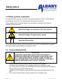
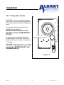
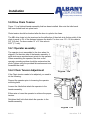
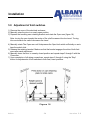
RCA L Owner’s Manual RCA L Version 1.0 Components 7 1 2 8 3 4 5 6 (7) Safety 3 RCA L 2 Version 2.0 Components The M&I Re-Coil-Away door contains the following parts: (1) Header Assembly Contains the curtain, operator (2) Door Curtain SBR, EPDM (3) Side Frames Painted steel (4) Pneumatic Safety Edge Self monitoring (5) Drive System Jack Shaft operator (6) Safety Photocell ADS Photocells – either reflective or thru-beam (7) Springs 50,000 cycle (8) Chains and sprockets Size 60 chain (9) Idler Barrel (not shown) Helps guide the curtain into the side frames (10) Hoods (Optional) (not shown) RCA L 3 Version 2.0 Table of Contents 1 2 3 4 5 Manufacturer and general information .........................................................................6 1.1 Manufacturer..............................................................................................................6 1.2 Copyright ...................................................................................................................6 Product description ........................................................................................................7 2.1 Function and design of this door................................................................................7 2.1.1 Principle .................................................................................................................7 2.1.2 Door Speeds ..........................................................................................................7 2.2 Electric safety features ..............................................................................................7 2.2.1 Additional Safety systems ......................................................................................8 2.3 Drives.........................................................................................................................8 2.4 Technical Data...........................................................................................................8 2.5 Warranty Information .................................................................................................9 2.5.1 Limited Warranty ................................................................................................9 2.5.2 RE-COIL-AWAY SBR Curtain Limited Warranty .................................................10 Safety advice .................................................................................................................11 3.1 Area of application. ..................................................................................................11 3.2 Responsibilities of the operator ...............................................................................11 3.3 Safety symbols explanation..........................................................................................12 3.4 General Safety Advice................................................................................................12 Storage and transport ..................................................................................................14 4.1 Storage ....................................................................................................................14 4.2 Dimensions of the fitted door ...................................................................................14 4.3 Devices and aids allowed for the transport ..............................................................14 4.4 Transport to the installation place............................................................................14 Installation .....................................................................................................................15 5.1 Inspection of the shipment.......................................................................................15 5.2 Installation preparations...........................................................................................15 5.3 Starting the install ....................................................................................................16 5.3.1 Setting up the side fames ................................................................................16 5.4 ......................................................................................................................................17 Preparing the header assembly for lifting ...........................................................................17 5.4.1 Lifting locations ......................................................................................................17 5.4.2 Lifting with a fork lift .............................................................................................18 5.5 Installing the Header...................................................................................................19 5.6 Drive Chain Tension .....................................................................................................20 5.6.1 Chain Tension Adjustment ........................................................................................20 5.7 Counter Balance Springs..............................................................................................21 5.7.1 Pre-charging Springs.................................................................................................21 5.8 Closing the side frames ..............................................................................................22 5.8 Hand Chain Operator .................................................................................................23 5.9 Adjustment of limit switches.....................................................................................24 RCA L 4 Version 2.0 6.0 Service & Repair.............................................................................................................25 6.1 Customer Service .........................................................................................................25 6.2 Inspection and maintenance ......................................................................................25 6.3 Cleaning .......................................................................................................................26 6.3.1 Cleaning and maintenance of the door curtain ......................................................26 6.3.2 Cleaning and maintenance of the door curtain ......................................................27 6.4 Troubleshooting............................................................................................................27 6.4.1 How to wedge a curtain .........................................................................................27 6.4.2 Operator Troubleshooting ......................................................................................28 6.5 Repairs & Removals.....................................................................................................30 6.5.1 Removal and Re-installation of curtain in guides ...................................................30 6.5.2 Removal and Re-installation of curtain in bottom bar ............................................30 6.5.3 Repairs to rubber curtain – rips or perforations .....................................................30 6.5.4 Replacing the operator brake band ........................................................................32 6.5.5 Adjusting the operator brake band .........................................................................33 6.6 Maintenance Schedule .................................................................................................34 6.6.1 Gearbox .................................................................................................................35 6.7 Torque Specifications ...................................................................................................35 RCA L 5 Version 2.0 1 Manufacturer and general information 2003 ALBANY DOOR SYSTEMS This operational manual is part of the Re-Coil-Away door. 1.1 Manufacturer Manufacturer of this rapid roll door is: ALBANY DOOR SYSTEMS 975-A OLD NORCROSS ROAD LAWRENCEVILLE, GA 30045 PH: 1-877-925-2468 FAX: 770-338-5034 Internet: www.albanydoorsystems.com Email: [email protected] 1.2 Copyright All rights for this roll door type M&I Re-Coil-Away and the respective operation manuals are subject to copyright. Design copy of this door system will be legally prosecuted. No part of this operation manual may be reproduced without the prior permission of Albany Door Systems. Should you have any questions regarding our doors and services please do not hesitate to contact us. We shall be eager to help you in any way. RCA L 6 Version 2.0 2 Product description 2.1 Function and design of this door The model Re-Coil-Away is a vertically opening door. 2.1.1 Principle The door assembly consists of left and right side frames and a header assembly. The header assembly contains the curtain and the drive system already attached. The bottom beam is already attached to the curtain. Door comes standard with a balance system. The Re-Coil-Away door rolls the curtain material directly on and off a barrel assembly. The edges of this curtain are contained within the side frames via a patented windlok system while the curtain is being rolled or unrolled off the barrel. These side frames guide the curtain also and provide a seal. The bottom beam, located on the bottom of the curtain, contains a continuously monitored pneumatic safety edge. Activation of this device will stop the door and cause the door to reverse to a fully open position. The door also has a reversing photocell attached to the side frames of the door. 2.1.2 Door Speeds The maximum opening speed depends on the size of the door and sprocket size. Door Size Up to 12’ x 12’ 12’ x 12’ to 18’ x 18’ 1-Speed 18” per sec. 15” per sec Measured at 8 feet high. 2.2 Electric safety features Before each downward movement an internal test of the photocells and the control unit is performed (Safety classification 2). If a malfunction has been acknowledged, the drive power is interrupted (ACS-50 Control Panel) and the door will not operate to close the door. RCA L 7 Version 2.0 Product Description 2.2.1 Additional Safety systems Depending on the kind of application it may be useful to have additional sensors as safety features. This is especially true for a door with a high volume of human traffic or with low sized doors with a height under 10 feet (3m). Albany Door Systems offers a variety of safety systems for high-speed doors. Some examples could be any of the following: Light beam barriers, motion detectors, induction loops. For any other electrical requirement contact us at the factory. 2.3 Drives The Re-Coil-Away is operated with an electrical drive. Drive side is chosen by the end-user. The drive system has a 1-speed operator. The drive systems come in 3 different operating voltages: 208 VAC, 460 VAC, and 575 VAC. 2.4 Technical Data Door principle: Running direction: Roll door Vertical External door (also applicable as interior door) 18’ wide x 18’ high 18 inches per second @ 8 feet (Depends on door size) 18 inches per second @ 8 feet (Depends on door size) Interior or external mounting Electrical 208VAC, 460VAC, 575VAC 2.0 H.P. Built-in operator controls 24VDC IP54 - NEMA 12 Painted Steel SBR, EPDM See enclosed technical drawing See fixing drawings Application: Maximum Sizes: Maximum opening speed: Maximum Closing speed: Fitting position: Drive: Electric Power: Maximum Horse power: Control unit: Control voltage Motor protection category: Door frame: Curtain: Door dimensions and fitting space Fixing points: Technical changes resulting of product maintenance are subject to alterations RCA L 8 Version 2.0 Product Description 2.5 Warranty Information 2.5.1 Limited Warranty All door systems manufactured by Albany Door Systems are warranted from the date of purchase against defects in materials and workmanship as follows: (i) door systems in general...two (2) year; (Section 2.5.2) rubber curtains (DO NOT EVER USE PETROLEUM BASED PRODUCTS ON THE CURTAIN, IF DONE THIS VOIDS ALL WARRANTY ON THE CURTAIN MATERIAL). If within this period of time any part is found to be defective, new or re-manufactured parts will be furnished free of charge, F.O.B. our plant in Lawrenceville, Georgia, provided that recommended installation and maintenance procedures (as outlined in our Owners Instructions booklet) are followed. In cases where the manufacturer's warranty of certain parts connected with our door systems (i.e.: electrical motors, switches, etc.) is less than the Albany Door Systems warranty, the manufacturer's warranty will apply. The Albany Door Systems warranty does not include replacement of parts due to normal wear and tear, damage beyond the control of Albany Door Systems (i.e.: damage in transit, impacts, etc.), or any labor charges incurred in the removal and/or replacement of defective parts. Warranty claims must be made to Albany Door Systems (or to the authorized distributor from whom the purchase was made), and defective parts to be returned for verification or replacement must have a Return Goods Authorization Number, This number can be obtained from Albany Door Systems customer support. This phone number is 877-925-2468. RCA L 9 Version 2.0 Product Description 2.5.2 RE-COIL-AWAY SBR Curtain Limited Warranty LIFETIME WARRANTY ON SBR Curtain material. Albany Door Systems warrants to the original owner of the door that the door panel fabric and components (windlok) will be free of defects in material and workmanship for as long as the door is installed in it’s original opening or building. Only defects brought to the attention of Albany Door Systems during the warranty period will be covered by this warranty. Albany Door Systems will replace any component parts that are found to be defective upon inspection by an Albany Door Systems representative. This warranty does not cover damage caused by collision or other abuse of the product. Adjustments made to the Control Panel or to the mechanical operation of the door without the authorization of Albany Door Systems will void this warranty. The replacement provisions shall be the limit of Albany Door System’s responsibility under this warranty and Albany Door Systems shall not be responsible for any other losses or damages due to the operation of any door or parts covered by this warranty. No other oral or written representations made by Albany Door Systems or its agents are a part of this warranty unless specifically set forth in writing by an authorized Albany Door Systems official. DO NOT EVER USE PETROLEUM BASED PRODUCTS ON THE CURTAIN, IF DONE THIS VOIDS ALL WARRANTY ON THE CURTAIN MATERIAL. THE ABOVE SET FORTH WARRANTY IS SELLER'S SOLE WARRANTY. SELLER MAKES NO OTHER WARRANTY OF ANY KIND WHATSOEVER, EXPRESSED OR IMPLIED; AND ALL IMPLIED WARRANTIES OF MERCHANTABILITY AND FITNESS FOR A PARTICULAR PURPOSE WHICH EXCEED THE AFORESTATED OBLIGATION ARE HEREBY DISCLAIMED BY SELLER AND EXCLUDED FROM THIS AGREEMENT. RCA L 10 Version 2.0 Product Description 3 Safety advice 3.1 Area of application. The M&I Re-Coil-Away is used for the closing of door openings preferably in industrial buildings that are highly used area of automobiles or heavy equipment. As a flexible exterior door with resistance against wind and weather conditions, the door opens with a speed that is especially suitable for heavy traffic throughways. It ensures a smooth transport flow and reduces collisions. The M&I Re-Coil-Away door may also be applied to interior areas. 3.2 Responsibilities of the operator The M&I Re-Coil-Away door is designed and manufactured under consideration of safety technical specifications. This meets the highest standard of safety. However, this safety can only be reached in operational practice if all necessary measures are met. It is the duty of the operator of such door system to ensure all these measures and check its status. Please read the operation manual carefully and keep it in a safe place. The operator of the door is held to ensure especially that: • Installation, first operation, inspection, servicing, repair work and dismantling is only done by personnel that have been trained by the manufacturer. • Only to be operated by personnel that have been sufficiently assigned and authorized to operate this door system. • The door is only used according to the determined application (see above). • The door must be only operated in a functional perfect state and especially the safety features must be checked for function in regular intervals. • The operation manual should be kept at the site of the fitted door system in readable condition. • All safety and warning labels should not be removed from the machine and should also be kept readable. RCA L 11 Version 2.0 Safety advice 3.3 Safety symbols explanation The following safety symbols are used in the enclosed operation manual. These symbols should advise the reader of the important text they should read closely. These symbols point to existing danger for life and health of persons or the machine, material or the environment. Attention! Danger for persons or the door system Attention! Danger through electric power ? Important Information Advice labels situated directly at the door and the control box must absolutely be regarded and also be kept in good condition to be seen and read. 3.4 General Safety Advice WARNING THOROUGHLY READ THESE SAFETY PRACTICES PRIOR TO INSTALLING, OPERATING, OR SERVICING A HIGH-SPEED, RAPID ROLL® DOOR OR ELECTRICAL CONTROL PANEL. FAILURE TO FOLLOW THESE SAFETY PRACTICES MAY RESULT IN PROPERTY DAMAGE, PERSONNEL BODILY INJURY, OR DEATH. • • • • • RCA L Please read the operation manual carefully and keep it a safe place. The safety rules mentioned in this operation manual must definitely be kept. Do not use the door for purposes not defined. If the door is transferred to third person this operation manual must transferred also. Operation of the emergency lever may lead to partly opening/closing motion of the door. Do not drive through the door opening unless door is completely open. 12 Version 2.0 Safety Advice • In power loss condition the electrical drive for the door curtain can be unlocked using the disengagement chains and then the curtain hand chained upwards. When the disengage lever has been engaged the control system has been disable. • During operation of the door do not stick your hands in the side frames. Keep hands and feet clear of the door at all times. Stay clear of the door while it is operating. • Human traffic should be avoided within the working area of the door. Existing side doors for human traffic should be used instead. • Do not run through the door opening. Go upright and with normal pace. • Keep the working vicinity and the opening of the door in clear of obstructions. Maintain a clear door opening at all times. Obstructions may cause accidents. • Do not climb up the door • For all kind of work on the door the main switch (main disconnect) must be set to the OFF position and locked out to prevent power from being reset. • When damage occurs to the door (mechanically or electrically) turn off operational power immediately. This is especially true if you have damage of the curtain or drive system. • USE EXTREME CAUTION when it is necessary to service the control panel or the auxiliary control box while it is energized. The door must only be operated with the correct voltage and frequency. • Use only the auxiliaries and devices authorized by the manufacturer of the door. • The STOP Button on the front of the panel is a momentary stop ONLY!. The door will only stop the door for that cycle; motion detectors, floor loops, or any activating device can activate the door! To ensure that the door keeps from being activated, use the rotary disconnect on the front of the panel. • DO NOT EVER USE PETROLUM BASED PRODUCTS ON THE CURTAIN, IF DONE THIS VOIDS ALL WARRANTY ON THE CURTAIN MATERIAL. Pay attention to the general safety advises mentioned under the core point SAFETY but also the special safety advises mentioned in the other chapters of the operation manual. RCA L 13 Version 2.0 4 Storage and transport 4.1 Storage The partly pre-assembled door is delivered in a crate. An undamaged crate makes it possible to store the door externally for some days. The crate must be stored on even ground. The crate must not be removed before the start of installation. 4.2 Dimensions of the fitted door See technical drawings in the section 11 4.3 Devices and aids allowed for the transport The door should be lifted in such a way that tilting the crate sideways is avoided. 4.4 Transport to the installation place The components of the door system must only be taken from the transport crate at the place where the door is being installed. RCA L 14 Version 2.0 5 Installation 5.1 Inspection of the shipment The M&I Re-Coil-Away door is mostly pre-assembled before leaving the factory. The side frames together with the top roll are attached to a pallet at the time of leaving the factory. The door must be checked for possible transport damage and that all the components ordered with the door are with it. Check against the order statements. 5.2 Installation preparations Check the installation place with regard to the necessary fixing points and setup. If necessary a support construction or other installation possibilities must be set up. The side frames should be securing attached to a suitable mounting surface. Insulated panel walls, honeycomb bricks and lightweight partition walls must first be checked for installation use. Clear dimensions (width and height) of the door opening should be measured and compared with the order statements. The installation location must be secured for passenger and automobile traffic. Before installation the packing material must be removed. Also lower the bottom beam below the idler barrel before lifting into place. RCA L 15 Version 2.0 Installation 5.3 Starting the install 5.3.1 Setting up the side fames NOTE: Some wall surfaces are not ideal and may require shimming to keep the side frames square to each other. This will help eliminate photocell misalignment problems and curtain binding issues. The door is usually centered over the door opening. Also at this time establish a level line or mark on each side of the door opening (must be marked in order to establish a reference height in case of an uneven floor). This can be accomplished using either a water level or an optical measuring device. Measuring down from this mark to the floor on each side of the door opening will tell you if your floor is level at the points of installation for each of the side frames. (Example: If on side A, you measure from your level mark to the floor and it 46” and side B it measures 47”. This measurement tells you that Side A should be installed first right on the floor and that Side B will have to be raised 1” in order to be level with Side A). See figure 1. Door Height Opening Door Width Opening Figure 1 Mounting holes Once you have established which side frame to install first. You need to put up this side frame up and fully plumb and level it, as seen in figure 2. Centering the door in the doorway opening will allow for minor variations in the existing door opening Lintel NOTE: Along the inside of each side frame there are predrilled holes for mounting the side frame to the door opening. (See Appendix) RCA L Figure 2 16 Version 2.0 Installation 5.4 Preparing the header assembly for lifting Loosen and remove the lower idler barrel bolt (figure 5) and move the idler barrel out of the way (figure 6) before lifting the header assembly. Figure 6 Figure 5 5.4.1 Lifting locations There are eyebolts for lifting the header assembly into place, located on the header plates. Attach cable or chain that is rated for the weight of the header assembly. Be sure to balance the header assembly before lifting into place. Figure 7 WARNING: The cable or chain used for lifting the header assembly must not exceed a 45°° angle from vertical DANGER: A falling header assembly can result in SEVERE INJURY and POSSIBLE DEATH! RCA L Figure 8 17 Version 2.0 Installation 5.4.2 Lifting with a fork lift WARNING: You must not ever lift using the bottom beam or the idler barrel between the forks and the header assembly, damage can occur. You can place the forks of the forklift up under the top roll (figure 9). Not the header framework or the Idler Barrel, if done DAMAGE WILL OCCUR. Be careful to have the header assembly properly balance on the forks. Secure the header assembly to the forks to help prevent from falling. DANGER: A falling header assembly can result in SEVERE INJURY and POSSIBLE DEATH. Figure 9 RCA L 18 Version 2.0 Installation 5.5 Installing the Header While lifting the Header, align the holes on the installed side frames with the holes in the header assembly. Note that the idler barrel-bearing has been moved out of the way Never leave the header assembly unattended without fully bolting the header assembly to the side frames, or before removing lifting device and or leaving general area of the door installation. Figure 10 Once you have aligned the header, bolt the assembly to the side frames. Small doors have 2 bolts per side; larger doors have 3 bolts per side. These should be torque to 212 ft-lb. You must bring down the curtain before securing the idler bearing. Figure 11 RCA L 19 Version 2.0 Installation 5.6 Drive Chain Tension Figure 11 is a finished header assembly that has been installed. Also note the idler barrel has been bolted back into place back. Chain tension should be checked after the door is cycled a few times. Slack side The M&I drive chain is to be tensioned so the deflection of the slack side (bottom side) of the chain is equal to 2% of the distance between the shafts. For door over 12’ x 12’ this value is 3/8” (9.5 mm). For doors under 12’ x 12’ this value is 9/32” (7.1 mm). 5.6.1 Operator assembly The operator is not assembled to the door when it is shipped. On the drive side of the header assembly, 4 weld studs serve as attachment points for the operator. When assembling the operator, the slots on the operator mounting surface should be centered on the studs Tighten using the provided flat washers and nuts. Assemble the chain. 5.6.2 Chain Tension Adjustment Figure 12a If the Chain tension needs to be adjusted, you need to do the following: Support the operator prior to loosening the operator mounting bolts. Loosen the 4 bolts that attach the operator to the header assembly. Either raise or lower the operator to achieve the proper tension. Retighten the 4 bolts that attach the operator to the header assembly. Figure 12b RCA L 20 Version 2.0 Installation 5.7 Counter Balance Springs Figure 13 5.7.1 Pre-charging Springs The springs must be pre-charged with the door curtain in the up position. This pre charge amount is listed on the spring bracket, this should be should be stamped with numbers for example 3 S and 4 T. With S standing for the amount of pre-stretch in inches and T for amount of pre turns. You also stretch the spring at this time; this amount is also located on the same tag. You always charge in the up position as shown in figure 13. RCA L 21 Version 2.0 Installation 5.8 Closing the side frames Open the side frame covers as shown in figure 16. Bring the curtain down so it travels behind the idler barrel and down into the guides of the side frame. (If you need to get the bottom beam behind the idler barrel you can remove the bottom bolt on each side of the idler barrel, and swing it down out of the way.) Figure 16 Next figure 17 shows the guides closed and set to the proper clearance gap. This gap is a minimum of ½” (13 mm). This gap allows the curtain to travel within the guide freely. ½” RCA L 22 Version 2.0 Figure 17 Installation 5.8 Hand Chain Operator The operator is equipped with an emergency chain hoist and floor-level disconnect mechanism to operate the door manually, if necessary. To manually operate the door: Pull the disconnect chain downwards to the “disengaged” position (See figure 14a). A positive engaging coupling disengages the initial drive mechanism from electrical operation and transfers it to manual chain hoist drive. A switch disconnects the electrical controls to prevent injuries. Operate the door manually by pulling downward on one side of the chain. Pulling the other side will cause the door to move in the opposite direction (See figure 14b). To return to electrical operation, merely pull the disconnect chain to the “engaged” position” (See figure 14c) Figure 14a RCA L Figure 14b 23 Figure 14c Version 2.0 Installation 5.9 Adjustment of limit switches 1) Remove the cover of the electrical enclosure. 2) Manually raise the door to a nearly open position. 3) Depress the travelling cam retaining bracket and rotate the Open cam (figure 18). Note: turning the cam towards the center of the shaft increases the door travel. Turning the cam towards the switch decreases the travel. 4) Manually rotate The Open cam until it depresses the Open limit switch sufficiently so as to hear the switch click. 5) Release the retaining bracket. Make sure that the bracket engages the slots of both limit cams after each adjustment. 6) Manually lower the door to a nearly closed position and repeat steps 3 through 5 with the Close cam. 7) Upon completion of all wiring connections, repeat steps 2 through 6 using the “Stop” button for adjustments of limit switches to their final, exact positions. Figure 18 RCA L 24 Version 2.0 Service & Repair 6.0 Service & Repair 6.1 Customer Service In case of door maintenance, malfunctions or repair work, please contact the supplier or the manufacturer. Address of Customer Services Department ALBANY DOOR SYSTEMS 975-A Old Norcross Road Lawrenceville, GA 30045 PH 877-925-2468 Fax 770-338-5034 6.2 Inspection and maintenance Maintenance, inspection and service work at the doors is only to be performed by manufacturer-trained personnel. Before starting work on the door, the power must be disconnected by switching off the main power disconnect and then locked out. Then the control box needs to be checked for it’s powerless position with a respective device. Please observe that all used ladders, scaffoldings, or such, correspond with the valid safety regulations. The working area must be blocked for both vehicle and foot traffic. Lubrication oil on the floor, tools and other material should be removed from the floor when work has been finished. The necessary maintenance inspections, check-up and time intervals are list in the Inspection section. RCA L 25 Version 2.0 6.3 Cleaning 6.3.1 Cleaning and maintenance of the door curtain Do not ever use any petroleum-based products on the curtain. Clean curtain with a citrus based cleaner only. RCA L 26 Version 2.0 Service & Repair 6.3.2 Cleaning and maintenance of the door curtain Dust may be removed with a cloth. Harder dirt may be removed with water. Dirt, grease, or oil on metal may be removed with a citrus cleaner. 6.4 Troubleshooting 6.4.1 How to wedge a curtain Why would a curtain need a wedge? A wedge is used to correct uneven curtain build, which can be evidenced by the following symptoms: (a) Bottom bar tracks to either right or left thereby causing it to jam against the guide, (b) Bottom bar becomes out-of-level when door is in the open position, (c) Curtain tends to 'cone' in one direction on the barrel, as the door is rolling up. What is a wedge? A wedge is a piece of waste rubber (can be as large as 6" square by as much as 1/2" thickness), which is strategically placed on the drive barrel between the curtain and the barrel. It is secured with a self-tapping screw(s). How to determine where to fasten wedge. It is normal for a curtain to 'float' slightly from side to side as the door rolls up and down. Wedging is required only when there is a severe tracking problem such as listed above. The placement of a wedge can be determined in several ways. For example, if the bottom bar were tracking to the left as the door is opening, then the wedge would be fastened on the right end of the barrel. The wedge would then make the curtain roll-up faster on the right side, thus making the bottom bar track evenly between the guides. Should the door be tracking to the right, and then obviously the wedge should be fastened to the left end of the barrel. It is important to identify whether a door requires a wedge or if it has been installed out-oflevel. For instance, if a door rolls down with the bottom bar continually tracking to one side, eventually jamming near the floor, yet the curtain does not appear to 'cone', then the door is most likely out-of-level. To remedy the problem, it may be necessary to raise one of the end plates (which have slotted holes) to level the door. RCA L 27 Version 2.0 Service & Repair 6.4.2 Operator Troubleshooting RCA L 28 Version 2.0 Service & Repair RCA L 29 Version 2.0 Service & Repair 6.5 Repairs & Removals 6.5.1 Removal and Re-installation of curtain in guides 1. 2. 3. Utilizing a 3/8” wrench, unbolt the hinged front guide plates of both the left and right guides. Swing the front guide plates open and place them to the side. In the event that only the upper portion is hinged, raise the curtain and bottom bar until the bottom bar front angle is just below the open hinged portion. Then, lift the curtain one end at a time, out of the guides and set it outside the front guide plates. Lower the curtain slowly and make sure that it does not catch on the guides. To reinstall the curtain, follow the above steps in reverse order. Be sure to close and bolt the front guide plates prior to putting the door back into operation. 6.5.2 Removal and Re-installation of curtain in bottom bar 1. 2. With the curtain and bottom bar supported on a flat surface, loosen the bolts which secure the bottom bar to the curtain. Slip the curtain out of the bottom bar. To re-install the curtain back into the bottom bar, follow the above steps in reverse order. If the bottom bar is equipped with an electric reversing edge, be sure to unplug the connector when removing the bottom bar. In addition, take extreme care not to damage the electric reversing edge fabric. A puncture would allow moisture to penetrate it, thus causing premature failure of the reversing edge. 6.5.3 Repairs to rubber curtain – rips or perforations In order to work on the ripped or perforated area, the curtain must be taken out of the guides and lowered to the floor. Then, either work on an area supported by the floor or alternatively, a solid, level surface provided by a heavy table, for example. Refer to Figure 31 and 32 for positioning of the curtain prior to repairing it. 1. 2. 3. 4. 5. Using a utility knife, set it to a depth that will penetrate the rubber down to the nylon cord centre of the curtain and cut a rectangular or square section approximately 2" wider than the sides of the rip or perforation. Be careful not to cut the nylon cord itself (see Figure 31). Using a screwdriver and pliers and starting at one corner of the cut, peel the surface from the nylon cord centre within the perimeter of the cut. Using coarse sandpaper or a wire brush, remove loose rubber particles from the nylon cord centre. However, it is not necessary to have the fabric 100% bare. Flip the curtain over to the other side of the rip or perforation and repeat Step 1 through Step 3. From the 1/8" thick piece of repair rubber, cut some pieces to inlay into the prepared areas. Using a grinder with a sanding disc or a wire brush, roughen-up the inlay surfaces for bonding. RCA L 30 Version 2.0 Service & Repair 6. 7. Mix the adhesive as per the manufacturer's instructions and apply a liberal coating to the nylon cord fabric and the rough surfaces of the inlay rubber segments. Allow pieces to dry to the touch (about 15 to 20 minutes) and apply a second coating. Allow to set until tacky. Place the inlay segments into position and, using a rubber or rawhide mallet and a steel buckler, impact the entire area of the patch repeatedly. A high degree of impact ensures proper adhesion. Clamping is not acceptable. Allow the cement to cure thoroughly (1-1/2 to 2 hours) before moving the curtain. Finally, raise the curtain to an open position, re-insert it into the guides, close and re-bolt the guides, and resume normal operation. Figure 31 Figure 32 RCA L 31 Version 2.0 Service & Repair 6.5.4 Replacing the operator brake band RCA L 32 Version 2.0 Service & Repair 6.5.5 Adjusting the operator brake band RCA L 33 Version 2.0 Service & Repair 6.6 Maintenance Schedule Due to the unique design features of your new "RE-COIL-AWAY", the need for continual maintenance normally associated with conventional door systems (i.e.: guide rollers, hinges, door track, etc.) is virtually eliminated. The limited maintenance procedures listed below, when completed as indicated, will assure many years of trouble-free operation. MAINTENANCE PROCEDURE INTIAL 1,500 CYCLES EVERY 25,000 CYCLES OR 3 MONTHS EVERY 50,000 CYCLES OR 12 MONTHS LUBRICATE: Flange Bearing (4) NO NO Grease, 1 shot Drive Chain NO OIL OIL ADJUSTMENTS: Drive Chain Tension YES YES YES Brake band, Solenoid YES YES YES Guides, bottom bar & header assembly for rust or damage YES YES YES Guide Opening 1/2" NO YES YES All Fasteners (check for tightness) YES YES YES Limit Settings YES YES YES Reversing Edge (check for proper operation and any signs of damage) YES EVERY MONTH YES, every 350,000 cycles RCA L 34 Version 2.0 Service & Repair 6.6.1 Gearbox The gear construction is maintenance-free and has lifetime lubrication. (The output shaft should be kept rust free.) 6.7 Torque Specifications The table below list the type of bolt, its use, and what its torque setting is Size 5/8-11 x 2" 5/8-11 x 1-1/2" 5/8-11 x 1-1/2" 1/2-13 x 2" 1/2-13 x 1-1/2" 3/8-16 x 1-1/4” 3/8-16 x 1-1/2" 3/8-16 x 1" 3/8-16 x 1-1/4" 5/16-18 x 1-1/2" 1/4-20 x 1-1/4" RCA L Type Location Torque (ft-lb): Hex head bolt, Drive barrel bearing to end plate 212 Grade 8 Hex head bolt, End plate to side frame 212 Grade 8 Hex head bolt, End plate to spring mounting 212 Grade 8 brackets Hex head bolt, Idler barrel bearing to end plate 106 Grade 8 Hex head bolt, Header assembly to 106 Grade 8 truss/spreader bars Weld bolt Operator to endplate 31 Hex head bolt, Side frame angle to front cover 31 Grade 5 Socket head cap screw, Bottom beam 31 grade 5 to aluminum extrusion Button head screw, Bottom beam angle 31 Grade 5 thru fabric to flat bar Self tapping screw Curtain to drum tube 15 Hex head bolt, Break away bar on bottom beam 8 Grade 5 35 Version 2.0 RCA L Architectural Up to & including 12’x 12’ RCA L 36 Version 2.0 RCA L Architectural Over 12’x 12’ RCA L 37 Version 2.0