1
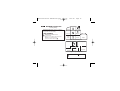
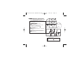
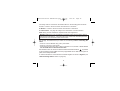
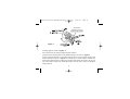
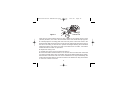
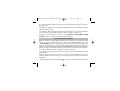
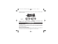
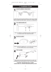
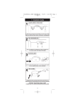
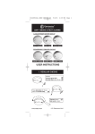
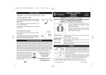
B16350-R0-Ei2100 SERIES-U&C.qxd
18/9/08
3:46 PM
Page 1
230V~
MULTI-SENSOR FIRE ALARM
with Rechargeable Lithium Cell Back-up
Model: Ei2110
Contains vital information on unit operation and installation. Read and retain carefully.
If you are just installing this unit this leaflet MUST be given to the householder.
INSTALLER INSTRUCTIONS
B16350-R0-Ei2100 SERIES-U&C.qxd
18/9/08
3:46 PM
Page 2
CONTENTS
3
1. QUICK GUIDE
1.1 INSTALLATION GUIDE
4
1.2 ALARM REMOVAL
5
2. MULTI-SENSOR FIRE ALARM FEATURES
6
3. HOW MANY ALARMS TO INSTALL
7
3.1 CATEGORIES OF SYSTEM
9
3.2 SELECTING ALARM TYPE
13
3.3 GRADE D, E & F SYSTEMS
14
15
4. POSITIONING ALARMS
4.1 LOCATIONS TO AVOID
16
17
5. INSTALLATION
5.1 MOUNTING & WIRING ALARMS
19
5.2 INTERCONNECTING ALARMS
23
25
6. ACCESSORIES
2
B16350-R0-Ei2100 SERIES-U&C.qxd
18/9/08
3:46 PM
Page 3
INSTALL IN THE CENTRE OF CEILING AT LEAST 300mm FROM
LIGHT FITTINGS & WALLS
INTERCONNECT ALL ALARMS
ENSURE MAINS POWER IS CORRECTLY CONNECTED TO L & N
TERMINALS ON ALL INTERCONNECTED ALARMS - OTHERWISE
UNITS WILL BE DAMAGED
DO NOT FIT ACTUAL ALARMS UNTIL ALL BUILDING WORK IS
COMPLETED TO AVOID CONTAMINATION. AFTER CHECKING
OPERATION, COVER ALARMS WITH DUST COVER UNTIL
REQUIRED FOR USE
DISCONNECT THE ALARMS BEFORE APPLYING HIGH VOLTAGE
TO WIRING (FOR INSULATION TESTS)
DO NOT ATTEMPT TO OPEN THE ALARM AS IT IS PERMANENTLY
SEALED FOR SAFETY
3
B16350-R0-Ei2100 SERIES-U&C.qxd
18/9/08
3:46 PM
Page 4
1.1 Installation Guide
DECIDE ON CORRECT POSITION
GREEN MAINS
LIGHT
PRESS AND HOLD THE TEST BUTTON ON THE ALARM. CHECK
THE ALARM AND ANY INTERCONNECTED UNITS SOUND.
AS THE TAMPER-PROOF CATCH ENGAGES. SWITCH ON MAINS
4
B16350-R0-Ei2100 SERIES-U&C.qxd
18/9/08
3:46 PM
Page 5
1.2 Alarm Removal
LOCATE REMOVAL SLOT
INSERT SCREWDRIVER
LOCATE THE ARROW ON THE FRONT FACE OF THE ALARM.
THE SLOT IS LOCATED DIRECTLY ABOVE THE ARROW.
INSERT A FLAT-BLADED SCREWDRIVER HORIZONTALLY
ABOUT 10mm INTO THE CENTRE OF THE REMOVAL SLOT
REMOVE ALARM
SLIDE ALARM OFF BASE
WITH THE SCREWDRIVER STILL INSERTED, PUSH THE LOWER
HALF OF THE ALARM AWAY FROM THE SCREWDRIVER, IN THE
DIRECTION OF THE ARROW ON THE COVER
HOLD THE LOWER HALF OF THE ALARM AND REMOVE FROM
THE BASE PLATE BY LOWERING THE ALARM TOWARDS
THE FLOOR.
5
B16350-R0-Ei2100 SERIES-U&C.qxd
18/9/08
3:46 PM
Page 6
2. MULTI-SENSOR FIRE ALARM FEATURES
The state of the art EI2110 Multi-Sensor Fire Alarm, with its Heat enhanced Optical
Smoke Sensor, has a significantly improved performance as described below.
1. Faster Response to a wider range of fires.
The combination of the ultra fast temperature sensing thermistor and the high
performance optical sensor within the unit, enhances the fire sensing performance
such that the unit detects all the 7 different Test Fires (TF) specified in the standard
BS ISO 7240-15: 2004. These Test Fires are designed to produce different levels of
smoke/heat and as such are a good test of the units performance to the different fires
that could possibly occur in the home.
2. Reduced Nuisance Alarms.
The unit can tolerate up to 50% higher levels of cooking fumes and steam when
compared with normal optical sensor alarms.
3. Increased Longevity and Ruggedness.
The unit can tolerate up to 100% more dust and contamination build-up when
compared with normal optical sensor alarms. This is due to the unique automatic
DUST* compensation built into the unit which monitors the contamination in the smoke
sensing chamber and adjusts the alarm trigger point accordingly.
*DUST – Dust Ups Sensor Threshold.
Additionally, the optical sensor chamber features a fine mesh insect screen that is
bonded to the plastic of the chamber. This significantly improves immunity to insect
contamination.
6
B16350-R0-Ei2100 SERIES-U&C.qxd
18/9/08
3:46 PM
Page 7
4. Replace Alarm Indicator.
If the optical sensor chamber becomes very heavily contaminated, the amber fault
light will flash once every 40 seconds to inform the user. Action can then be taken to
replace the unit, long before the contamination causes nuisance alarms.
5. Alarm Memory.
After a the unit has gone into alarm, the red alarm light will flash twice (1 second apart)
every 40 seconds to indicate that the unit has alarmed in the previous 24 hours.
Additionally, pressing the Test/Hush button on this unit will cause it to emit short, rapid
beeps instead of the normal alarm sound. Both these features allow easy
identification, for example, of the source of nuisance alarms during the night.
6. Single Person Interconnect Test
Pressing and holding the Test button on the unit causes the alarm to sound. On
releasing the test button, the alarm will immediately cease but all interconnected
alarms will continue to sound for 3 seconds. This allows easy audible check of alarm
interconnection.
3. HOW MANY ALARMS TO INSTALL
- CATEGORIES & GRADES The ideal system would consist of Multi-Sensor Fire Alarms installed throughout the
dwelling apart from the kitchen which should have a Heat Alarm installed (Note:
alarms should not be installed in toilets/bathrooms).
7
B16350-R0-Ei2100 SERIES-U&C.qxd
18/9/08
3:46 PM
Page 8
The Multi-Sensor Alarm can be installed for superior performance anywhere the
regulations specify an Optical Smoke Alarm or an Ionisation Smoke Alarm.
(The Ei2110 Multi-Sensor Fire Alarm can also be used and interconnected with an
Ei166RC Optical Smoke Alarm or an Ei161RC Ionisation Smoke Alarm if necessary).
The advice here follows the guidance in British Standard BS 5839-Part 6:2004 in
general (for further information see the BS standard itself).
The main reason for fitting alarms in dwellings is to ensure that when there is a fire,
sufficient early warning is given so that everybody can escape safely.
This means that the fire alarms should ideally be located in all escape routes and in all
rooms that contain potential sources of fire. Another important consideration is that the
alarm should be heard throughout the house – particularly in the bedrooms.
It is also important that nuisance/false alarms are minimised to ensure the units are
not disabled or ignored.
BS 5839-Part 6:2004 gives guidance on:
- how many alarms to install
- what type of alarm to use
- where to position alarms
The above points will depend on the type of dwelling to be protected and the level of
fire risk.
Fire Risk Assessment
The ‘Grade’ and ‘Category’ of system that should be installed depends on the fire risk.
8
B16350-R0-Ei2100 SERIES-U&C.qxd
18/9/08
3:46 PM
Page 9
It is therefore recommended that a Fire Risk Assessment is undertaken. The Risk
Assessment would be based on a combination of probabilities:
- fire occurring
- injury or death to occupant
- system operating correctly with a fire
- early detection and warning to occupants in the event of a fire.
The greater the risks, the more comprehensive and reliable systems are needed.
3.1 Categories of System
There are three Categories of LD systems for Life protection in Dwellings that can be
installed, depending on the fire risk and regulations.
Please see following pages for detailed information.
9
B16350-R0-Ei2100 SERIES-U&C.qxd
LD3
18/9/08
3:46 PM
Page 10
MINIMUM PROTECTION
for existing dwellings
Shower
Bedroom
Minimum Protection LD3: Alarms in all hallways,
stairways and circulation areas that form part of the
escape routes from the dwelling.
Bedroom
Multi-Sensor Fire Alarms located:
on each storey
every 7.5 m of hallways and escape routes
within 3m of all bedroom doors
(apart from toilets & bathrooms )
Bathroom
Living
Room
Garage
Kitchen
Multi Storey Dwelling LD3
Bedroom
Bedroom
Bathroom
Bedroom
Kitchen / Dining Room
Living Room
Single Storey Dwelling LD3
Multi-Sensor Fire Alarm
10
do not fit alarm
B16350-R0-Ei2100 SERIES-U&C.qxd
18/9/08
3:46 PM
Page 11
LD2 ADDITIONAL PROTECTION
for new or materially altered dwellings or existing dwellings
with poor structural fire precautions
Shower
Bedroom
Additional Protection LD2: As LD3, but in addition
alarms in all rooms or areas that present a high fire
risk to occupants.
Bedroom
Multi-Sensor Fire Alarms located:
on each storey
every 7.5 m of hallways and escape routes
within 3m of all bedroom doors
(apart from toilets & bathrooms )
Bathroom
Living
Room
Heat Alarms located in:
each Kitchen
(Heat Alarms must be within 5.3m of potential fire
sources)
Garage
Kitchen
Multi Storey Dwelling LD2
Bedroom
Bathroom
Kitchen / Dining Room
Multi-Sensor Fire Alarms or Heat Alarms located in:
each Living room (i.e. most frequently used
daytime room)
Bedroom
Bedroom
Living Room
Single Storey Dwelling LD2
Multi-Sensor Fire Alarm
Heat Alarm
11
do not fit alarm
B16350-R0-Ei2100 SERIES-U&C.qxd
LD1
18/9/08
3:46 PM
Page 12
OPTIMUM PROTECTION
for dwellings where occupants may be at high risk (e.g. elderly)
Shower
Bedroom
Optimum Protection LD1: As LD2, but in addition
alarms should be located in all rooms and other areas
of the dwelling. (apart from toilets or bathrooms)
Multi-Sensor Fire Alarms located:
on each storey
every 7.5 m of hallways and escape routes
within 3m of all bedroom doors
in all other rooms & areas other than listed below
(apart from toilets & bathrooms )
Heat Alarms located in:
each kitchen
garages
(Heat Alarms must be within 5.3m of potential fire
sources)
Bedroom
Bathroom
Living
Room
Kitchen
Garage
Multi Storey Dwelling LD1
Bedroom
Bathroom
Kitchen / Dining Room
Multi-Sensor Fire Alarms or Heat Alarms located in:
each Living room (i.e. most frequently used
daytime room)
Bedroom
Bedroom
Living Room
Single Storey Dwelling LD1
Multi-Sensor Fire Alarm
Heat Alarm
12
do not fit alarm
B16350-R0-Ei2100 SERIES-U&C.qxd
18/9/08
3:46 PM
Page 13
3.2 Selecting Alarm Type
Multi-Sensor Fire Alarm & Heat Alarm Selection
Locations & Performance
Alarm Type
Multi-Sensor
Fire Alarm
Heat
Alarm
Locations
Hall, Corridors, Escape Routes
Kitchens
2
1
Living Rooms
Bedrooms
Shower / Bathroom
Fire Response
Slow Smouldering Fires (polyurethane foam, ignited bedding etc.)
Fast Flaming Fires (flaming wood/plastic, oil, solvents, chip pans etc.)
Temperature >580C
3
4
Nuisance Alarm Immunityy
Cooking Fumes
Steam, Condensation & Dust Build-up
- Not Suitable
- Better
- Good
13
- Best
2
B16350-R0-Ei2100 SERIES-U&C.qxd
18/9/08
3:46 PM
Page 14
1 Some Fire authorities (concerned with the slow response of Heat Alarms) advise that Smoke Alarms
(or Multi-Sensor Alarms) should be fitted. This is acceptable according to BS 5839-6 provided there are
clearly not going to be problems with nuisance alarms. Fit Heat Alarms only if nuisance alarms are very
likely and it is acceptable that a warning will only be given by the Heat Alarm when there is a very
significant flaming fire in the room. If the door(s) and windows are not closed to contain the fire and heat,
it is extremely unlikely that the Heat Alarm would respond before a Multi-Sensor Alarm sited outside in
the corridor.
2 In enclosed kitchens with doors closed.
3 Fast flaming fires generate considerable amounts of heat. The Multi-Sensor Fire Alarm has a heat
enhanced optical smoke sensor to improve the response of the sensor to these types of fires.
4 Do not install in kitchens.
Improved Audibility
The effectiveness of Category LD2 and LD3 systems can be significantly enhanced if an
additional alarm (interconnected) is installed in the master bedroom. This will help ensure that a
responsible person will quickly be alerted to a fire and can arrange for an orderly evacuation of
children and other vulnerable occupants.
3.3 Grade D, E & F Systems
The mains powered, with battery back-up, Multi-Sensor Fire Alarm covered by these instructions
will meet the requirements for a Grade D Systems (and exceed Grades E & F).
A Grade D system is needed for:
- new or materially altered dwellings up to three-storeys, with no floor over 200m2 in area
- existing dwellings with poor structural fire precautions, up to three storeys, with no floor over
200m2 in area
- Houses in Multiple Occupation (HMOs) of one or two-storeys, with no floor over 200m2 in area
14
B16350-R0-Ei2100 SERIES-U&C.qxd
18/9/08
3:46 PM
Page 15
- Individual dwellings units of two or more rooms in HMOs
Check that a Grade D system is adequate for the dwelling into which the system is being installed.
4. POSITIONING ALARMS
The locations must comply with applicable building regulations.
Hot smoke rises and spreads out, so a central ceiling position is the preferred location.
The air is “dead” and does not move in corners, therefore alarms must be mounted away
from corners. Place the unit:
- At least 300mm away from walls. See Figure 1.
- At least 300mm from any light fitting or decorative object which might obstruct smoke /
heat entering the alarm.
300mm (min)
300mm
900mm
Figure 1
Figure 2
15
B16350-R0-Ei2100 SERIES-U&C.qxd
18/9/08
3:46 PM
Page 16
Note: Ceiling mounting is recommended - do not wall mount alarms.
Sloping Ceiling
In areas with sloping or peaked ceilings install the alarm 900mm from the highest point
measured horizontally (see Figure 2). This is because “dead air” at the apex may
prevent smoke from reaching the unit.
4.1 Locations To Avoid
DON’T place Multi-Sensor Fire Alarms in any of the following areas:
• Bathrooms, kitchens, shower rooms, garages or other rooms where the alarm may be triggered by
steam, condensation, normal smoke or fumes. Keep at least 6 metres away from sources of normal
smoke/fumes.
DON’T place Heat Alarms in any of the following areas:
• Bathrooms, shower rooms or other rooms where the unit may be triggered by steam or
condensation.
DON’T place Multi-Sensor Fire Alarms in any of the following areas:
• Places where the normal temperature can exceed 40°C or be below 4°C (e.g. attics, furnace
rooms, directly above ovens or kettles etc.) as the heat/steam could cause nuisance alarms.
• Near a decorative object, door, light fitting, window moulding etc., that may prevent smoke or
heat from entering the unit.
• Surfaces that are normally warmer or colder than the rest of the room (e.g. attic hatches).
Temperature differences might stop smoke or heat from reaching the unit.
16
B16350-R0-Ei2100 SERIES-U&C.qxd
18/9/08
3:46 PM
Page 17
• Next to or directly above heaters or air conditioning vents, windows, wall vents etc. that can
change the direction of airflow and cause rapid temperature fluctuations.
• In very high or awkward areas (e.g. over stairwells) where it may be difficult to reach the unit (for
testing, hushing etc.).
• Locate away from very dusty or dirty areas as dust build-up in the optical sensor chamber can
impair performance. It can also block the insect screen mesh and prevent smoke from entering
the chamber.
• Locate the unit at least 1m from dimmer controlled lights and wiring as some dimmers can cause
interference.
• Locate the unit at least 1.5m and route wiring at least 1m away from fluorescent light fittings as
electrical “noise” and/or flickering may affect the unit. Do not wire into the same circuit as
fluorescent lights or dimmers.
• Do not locate in insect infested areas. Small insects getting into the optical sensor chamber can
cause intermittent alarms. Insects and contamination on the heat sensor can increase its
response time.
5. INSTALLATION
The Alarm is designed to be permanently mounted, using it’s own built-in terminal
block to connect it to the mains. The mounting plate can be screwed directly to the
ceiling. Alternatively it can be screwed to a standard junction box. It requires a current
of 60mA. The Alarm must not be exposed to dripping or splashing. There are important
markings on the underside of the alarm.
IMPORTANT PRECAUTION: Do not install alarms in new or renovated buildings
until all work is completed (including floor coverings) and the building has been
17
B16350-R0-Ei2100 SERIES-U&C.qxd
18/9/08
3:46 PM
Page 18
fully cleaned. The wiring can be installed when appropriate. (Excessive dust and
debris from building work can contaminate the optical sensor chamber or heat
sensor and cause problems. It will also invalidate the guarantee). If it must be
installed, first cover it completely, particularly around the edges, with a dust
cover (eg. with the elasticated cover supplied or a plastic bag), until all cleaning
is finished.
The alarm must not be connected when the house wiring insulation is being checked
with high voltages.
i.e. Do not use a high voltage insulation tester on the alarm.
WARNING: Mains operated alarms should be installed and interconnected by a
qualified electrician in accordance with the Regulations for Electrical Installations
published by the Institution of Electrical Engineers (BS7671). Failure to install this alarm
correctly may expose the user to shock or fire hazards.
WARNING: The alarm must be continuously powered 24 hours a day so it is important
that it is not on a circuit that can be turned off by a switch.
Note: BS 5839-6: 2004 gives the following recommendations regarding the mains supply to be used in a
Grade D system. The power supply for the alarms should be derived from the public electricity supply to
the dwelling. The mains supply to the alarms should take the form of either:
(a) an independent circuit at the dwelling’s main distribution board, in which case no other electrical
equipment should be connected to this circuit (other than a dedicated monitoring device installed to
indicate failure of the mains supply to the alarms); or
(b) a separately electrically protected, regularly used local lighting circuit.
Alarms should be connected on a single final circuit, unless the means of interconnection is by radio
signals (e.g. RadioLINK).
(See BS 5839-6: 2004 for further information)
18
B16350-R0-Ei2100 SERIES-U&C.qxd
18/9/08
3:46 PM
Page 19
5.1 Mounting & Wiring Alarms
1. Select a location complying with the advice in previous sections (see pages 8-18).
2. Disconnect the AC mains supply from the circuit that is going to be used.
3. Lift off the wiring cover as shown in Figure 3.
FOAM CEILING GASKET
INSERT SCREWDRIVER
TO LIFT AND REMOVE
WIRING COVER
Figure 3
19
B16350-R0-Ei2100 SERIES-U&C.qxd
18/9/08
3:46 PM
Page 20
The wiring must be connected to the terminal block on the mounting plate as follows:
L: Live - connect to the house wires coloured brown or marked L.
N: Neutral - connect to the house wires coloured blue or marked N.
IC: Interconnect - see page 23 & Figure 6 for information on interconnection.
Note: Wiring must be installed in compliance with local regulations.
Warning: Mixing the Live and Neutral connections when interconnecting alarms
will damage all the alarms - ensure that the same colours are used throughout the
premises for Live, Neutral and Interconnect wires.
We strongly recommend that you check for the following before connecting the
alarm:
• check for Live and Neutral using a two probe tester.
• check for Live using a neon tester.
• check that the Interconnect wire is NOT connected to Live, Neutral or Earth. Do not
use an Earth wire for the Interconnect line.
N.B. The alarm does not need to be earthed. However the terminal marked
is provided
for the convenience of the installer so that any copper Earth wire or cable coloured green &
yellow, can be safely terminated.
To interconnect alarms connect all the IC terminals together as shown in Figure 4 (see
“Interconnecting Alarms” section on page 23).
20
B16350-R0-Ei2100 SERIES-U&C.qxd
18/9/08
3:46 PM
Page 21
REMOVEABLE
TRUNKING DOOR FOR
Figure 4
4. If the mains wires are recessed, bring the wires through the rear hole in the
mounting plate as shown in Figure 4.
If the mains wires are being brought along the surface:
(a) position the mounting plate so the cable trunking is as shown in Figure 4.
(b) the mounting plate has a removable section, take it out to interface directly with
25mm trunking as shown in Figure 5. If interfacing to 16mm trunking carefully cut
around the marked section, leaving the top intact and replace the section. (If you are
not using surface wiring, the removable section must be left in place for electrical
safety reasons).
21
B16350-R0-Ei2100 SERIES-U&C.qxd
18/9/08
3:46 PM
Page 22
Figure 5
There are two other positions which are also suitable for the surface wiring to enter
(and exit) the alarm, one next to the removable section and another directly opposite.
5. Carefully align the mounting plate and screw into place. Connect the wires to the
terminal block. With recessed wiring, ensure the rear gasket seals around the edge of
the hole in the ceiling or wall. This is to prevent air draughts affecting the smoke/heat
entering the alarm. If the hole is too large or the alarm does not seal it, it should be
sealed with silicone rubber or equivalent.
6. Replace the wiring cover.
7. Carefully line up the unit on the base and slide on.
8. Press and hold the test/hush button for 10 seconds. The horn will sound. Check that
any interconnected alarms also sound within this period. With the Multi-Sensor Alarm,
the test button sounds the local horn and on release this horn stops immediately, and
all the interconnected alarms can then be heard in the distance as they will continue
to sound for a further 3 seconds.
22
B16350-R0-Ei2100 SERIES-U&C.qxd
18/9/08
3:46 PM
Page 23
9. Connect the mains power to the alarm circuit. Check the green light on the front of
the alarm is on.
10. Attach the ‘Smoke Alarm’ identification label provided to the distribution board to
identify the alarm circuit.
11. Attach the ‘Mains Smoke / Heat Alarms’ label provided on or near the distribution
board and write in date installed and the number of alarms on the circuit.
Ensure the alarm operates correctly - see “TESTING & MAINTAINING YOUR
ALARM” section on page 8 of the USER INSTRUCTIONS.
5.2 Interconnecting Alarms
Note: A maximum of twelve Ei2110 Multi-Sensor Fire Alarms and/or Ei164RC Heat
Alarms may be interconnected along with an Ei128R/Ei128RBU relay (see
“ACCESSORIES” section on page 25). (Note the Multi-Sensor Fire Alarm Ei2110 can
also be interconnected to Ei141/144/146/161RC/166RC Smoke/Heat Alarms if
required). It can also be interconnected to Ei261ENRC/261DENRC Carbon Monoxide
Alarms provided an Ei1529RC Remote Control Switch is incorporated in the system see page 25. Make electrical connections as shown in Figure 6.
If you wish to connect more than twelve alarms contact your local distributor (see page
28 for details).
Systems using more than 3 or 4 alarms must be very carefully planned to ensure
nuisance alarms are not excessive. e.g. from cooking fumes or steam. The following is
suggested:
• A Remote Control Switch (model Ei1529RC) should be incorporated into the system
23
B16350-R0-Ei2100 SERIES-U&C.qxd
18/9/08
3:46 PM
Page 24
and be readily accessible to all occupants so that the source of an alarm can be
quickly identified.
• All alarms must be cleaned and maintained regularly.
• A qualified person must be on call to quickly remove any nuisance units (i.e. units
with red light flashing rapidly) which are causing all the other alarms to sound.
WARNING: Do not connect these alarms to any other type of Ei Alarm (apart from
those listed above) or to any other model produced by another manufacturer. Doing so
may damage the alarms and could result in a shock or fire hazard.
Wiring must be installed in compliance with local regulations.
In the UK it is recommended that the following coloured cores are used (for
example with triple flat 6243YH cable).
230V supply
Brown
Neutral
Grey - sleeved blue at terminations
Interconnect
Black
In the Republic of Ireland consult the local regulations as they are different from the
UK regulations.
The interconnect wire (minimum 0.75mm2 cable) must be treated as if it was Live. It
should be insulated and sheathed.
A maximum of 250 metres of wire can be used (maximum resistance between detectors 50
Ohms).
Alarms should be interconnected only within the confines of a single family living unit. If
they are connected between different units there may be excessive nuisance alarms.
24
B16350-R0-Ei2100 SERIES-U&C.qxd
18/9/08
3:46 PM
Page 25
Everybody may not be aware that they are being tested or that it is a nuisance alarm
caused by cooking etc.
Figure 6
Ensure the alarms operate correctly - see “TESTING & MAINTAINING YOUR
ALARM” section on page 8 of the USER INSTRUCTIONS.
6. ACCESSORIES
Relay Module Ei128R:
The Ei128R module has a relay rated at 250V AC / 5 Amps. This is useful for triggering
a remote device or remote signalling etc. Also available is the Ei128RBU Relay Module
which has battery back-up.
Remote Control Switch Ei1529RC:
The Remote Control Switch is recommended for systems with three or more alarms. It
allows the user to perform the following functions from a remote location:
25
B16350-R0-Ei2100 SERIES-U&C.qxd
18/9/08
3:46 PM
Page 26
LOCATE - If alarms sound press Locate to allow source of alarm to be identified audibly.
HUSH
- Press Hush to silence nuisance alarms.
TEST
- Operate weekly to Test the alarms.
MAINS CHECK - Test will not work with mains absent.
RadioLINK Base Ei168RC:
RadioLINK Bases are used to eliminate interconnect wiring and instead interconnect
alarms using radio signals. This allows quick and easy installation as well as easy
extension at a later date. The Ei2110 Multi-Sensor Fire Alarm (and Ei160RC Series
Alarms) simply slide on to the Ei168RC RadioLINK Base. Each alarm in the system
would need to be mounted on a RadioLINK Base.
An Ei411H RadioLINK Remote Control Switch is also available that offers additional
control functions similar to the Ei1529RC covered on page 25.
26
B16350-R0-Ei2100 SERIES-U&C.qxd
18/9/08
27
3:46 PM
Page 27
B16350-R0-Ei2100 SERIES-U&C.qxd
18/9/08
3:46 PM
Page 28
Aico Ltd. Mile End Business Park, Maesbury Rd,
Oswestry, Shropshire SY10 8NN, U.K.
Tel: 0870 758 4000
www.aico.co.uk
Ei Electronics. Shannon, Co Clare, Ireland. Tel: 061 471277
www.eielectronics.com
© Ei Electronics 2008
P/N B16350 Rev0
28