1
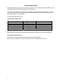
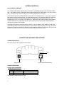
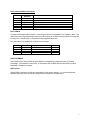
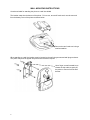
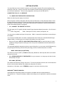
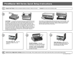
LCM25 Desktop
Operator’s Manual
Printek, Inc.
1517 Townline Road
Benton Harbor, MI 49022
800-368-4636
www.printekmobile.com
Printek Part Number 6789 Rev A
Table Of Contents
Introduction ................................................................................................................................................... 1
Notes on Printer Firmware Revisions (Including Flash).............................................................................. 1
Copyright Notice And Disclaimer ................................................................................................................ 1
Modes Of Operation...................................................................................................................................... 2
Idle Mode .................................................................................................................................................... 2
Spooling Mode ............................................................................................................................................ 2
Paper............................................................................................................................................................. 3
Loading Paper............................................................................................................................................. 3
Paper Out and PAPER LID Sensors........................................................................................................... 3
Status Indications.......................................................................................................................................... 4
Printer Operation and Programming ............................................................................................................. 5
Data Buffer .................................................................................................................................................. 5
Spooling Mode ............................................................................................................................................ 5
Character Printing and Fonts ...................................................................................................................... 5
Graphics Printing and Other Programming Modes..................................................................................... 5
Interface Details ............................................................................................................................................ 6
RS-232 Serial Interface............................................................................................................................... 6
Connections and EMC Precautions .............................................................................................................. 6
Connector Details........................................................................................................................................ 6
Connector Pinouts....................................................................................................................................... 6
Data Cable .................................................................................................................................................. 7
EMC Statement........................................................................................................................................... 7
EMC Caution............................................................................................................................................... 7
Wall Mounting Instructions ............................................................................................................................ 8
Getting Started .............................................................................................................................................. 9
Connecting to a PC – A Checklist............................................................................................................... 9
Windows™ Printer Drivers .......................................................................................................................... 9
Your Application Program ......................................................................................................................... 10
Technical Support ..................................................................................................................................... 10
INTRODUCTION
This document is an Operator’s Manual, written for the person connecting and using the PrintekMobile
LCM25 Desktop thermal printer. Please read this document carefully before making any connection.
A separate Programmer’s Manual provides details of the control codes, and describes the internal
operation of this product.
NOTES ON PRINTER FIRMWARE REVISIONS (INCLUDING FLASH)
Printek, Inc. reserves the right to modify and improve the firmware in its printer products at any time.
While every effort is made to ensure backward compatibility, no guarantee in this respect is given or
implied.
The LCM25 Desktop printer includes a flash programmable microcontroller. This allows firmware
upgrades under customer control. Please contact Printek Technical Support for more information.
COPYRIGHT NOTICE AND DISCLAIMER
Copyright © Printek, Inc. 2010
Copyright © Able Systems Limited 2005
Printek® is a registered trademark of Printek, Inc.
Fujitsu® is a registered trademark of Fujitsu Limited.
1
MODES OF OPERATION
The printer has two operating modes when not actually printing:
"Idle Mode": ready to accept data, but no data are in the buffer awaiting printing, and the printer is
not printing;
"Spooling Mode": active, but storing data for later printing.
Modes are indicated by different color combinations on the front-panel Status Indicator. No light is
emitted in sleep mode.
There is no power switch, the printer is permanently powered on when the power supply is attached.
IDLE MODE
In idle mode, the printer is ready to receive data which will be printed as soon as complete lines or
graphics patterns are decoded. It responds to the paper feed button in the normal way, and can also
produce a self test printout.
SPOOLING MODE
In spooling mode, data are received and stored, but not printed. This is useful when printing needs to be
suppressed during data transfer (for example in mobile radio systems); or when the printer is unable to
print because the paper has run out or the lid is open.
The printer will automatically enter spooling mode when the paper is out, when the paper lid is open, if
some other error condition occurs, or alternatively by command from the host. Spooling mode may be
cleared by host command, automatically when the error condition is cleared, or by "double-clicking" the
feed button.
2
PAPER
Pressing the paper feed button when the printer is idle advances paper at typically two inches per
second, depending on the power supply voltage. However, the paper feed button has several additional
functions:
A single press and release of the button:
in idle or spooling mode, advances paper;
in sleep mode, wakes up the printer into idle mode;
"Double-clicking" the button: (i.e. pressing and releasing twice in quick succession just like a PC mouse)
in idle mode, prints a self test message including the firmware version, encoded calibration
data, and the full character set;
in spooling mode, or having been out of paper, prints any stored data and enters idle mode.
Some of the functions of the paper feed button can be invoked or disabled under control of the host.
LOADING PAPER
The procedure for loading paper is as follows:
1.
2.
3.
Slide the Lid Release Button forwards until the Lid springs open.
Unwind a small amount of paper from the roll and Insert the Paper Roll into the Printer.
Close the Lid down, and the paper is loaded.
After loading, check that the paper advances properly, and tear off any excess by pulling the paper
sharply towards you across the serrated tear bar. In the event of a jam or other paper loading problem,
release the lid and straighten the paper before closing again.
PAPER OUT AND PAPER LID SENSORS
A reflective optical Paper Out sensor within the mechanism detects an out-of-paper condition, and/or
senses black marks to register with pre-printed forms. A mechanical sensor detects when the paper lid is
open.
By default, the printer enters Spooling mode automatically if either sensor becomes active. Spooling
mode is automatically exited, and any stored data printed, when new paper is loaded and the lid closed.
This behavior may be modified. Please refer to the Programmers’ Manual for details of how to configure
these functions.
3
STATUS INDICATIONS
The Status Indicator at the front of the printer has a number of color combinations, which repeat in up to a
4-phase pattern to provide status information (see table below).
In summary, if the indicator is constant green it indicates that the printer is operating normally. Flashing
on and off indicates that Spooling mode is active and no printing can take place. Red warns of a low
power supply voltage or other problem.
No light indicates that the unit is off.
Status Indicator Pattern Table
Pattern
Constant Green
Fast Flashing Green
Long Green - Short Red
Short Green - Short Red
Fast Flashing Red
No light
Power Status
Running
Running
Low Voltage
Low Voltage
Error Condition
Printer is Off
Buffer Mode
Normal
Spooling *
Normal
Spooling *
Spooling (Printing prohibited)
* (Spooling Mode may have resulted from Paper Out or Paper Door Open conditions)
Although this table may seem complicated, few applications will produce many of the combinations.
Other Status Indicator Patterns
Other patterns may be programmed into the printer by the system designer.
Please refer to the Programmer’s Manual for details of how to configure these functions.
4
PRINTER OPERATION AND PROGRAMMING
The LCM25 utilizes a Fujitsu FTP-628MCL103 printer mechanism, with a fixed (parallel) print head with
384 horizontally-arranged thermal elements. The paper is advanced by a stepper motor, and printing
takes place in a single dot row for each step of the paper. Each printed dot is approximately 0.005”
square. The printing speed and dot density are controlled according to the power supply voltage and the
head temperature.
Various printing modes, including graphics, are invoked by 'Escape' sequences. Control codes and
status report protocols are described in detail in the Programmer’s Manual.
DATA BUFFER
The printer has a nominal 20k byte buffer to optimize throughput: this enables data to be received into the
buffer while previous lines are being printed. Printing will be initiated on receipt of a valid logical line of
data or a complete graphics pattern.
The buffer may be cleared by data command or by a hardware reset. A partially full line will be printed on
receipt of an appropriate control code, or after a programmable timeout delay.
SPOOLING MODE
Spooling mode can be entered by:
a command from the host;
Paper Out condition or Paper Lid open condition being sensed;
an error condition (e.g. head over temperature, power supply over voltage, etc).
In spooling mode, the buffered data are stored without being printed until the mode is exited by:
a command from the host;
the 'causing condition' (e.g. Paper Out or Paper Lid open) being cleared;
the paper feed button being double-clicked.
CHARACTER PRINTING AND FONTS
The default 32-column character set is formed from a 24x10 dot matrix, and is based on the industry
standard IBM® character set Code Page 437. This character set has been modified to include the Euro
symbol (‘€’) at position 80H (128 Decimal), in place of the usual capital C with cedilla (‘Ç’).
Various combinations of single or double width, single or double height, inverted, underlined, and other
attributes may be mixed within a line.
Customized fonts may be created using a font editor utility, and downloaded to the printer. Only a single
custom font may be loaded in the printer at one time. Contact Printek Technical Support for more
information on the font editor utility.
GRAPHICS PRINTING AND OTHER PROGRAMMING MODES
Various dot-addressable graphics modes are supported, at up to 384 dots per line. The Windows driver
operates in the graphics mode. Refer to the Programmer’s Manual for full details of this and other
advanced programming modes.
5
INTERFACE DETAILS
RS-232 SERIAL INTERFACE
The LCM25 has an industry standard RS-232 interface. The default parameters are 9600 baud, 8 data
bits, 1 stop bit and no parity. Other baud rates can be programmed by control codes, or by using a setup
utility. Contact Printek Technical Support for information regarding the setup utility.
Serial data is expected in standard RS-232C format with -12V meaning 'mark' or '1' and +12V a logical '0',
with reference to the common ground. The serial data output line, TxD, transmits XON/XOFF and status
information to the host at the same Baud rate and in the same format as the serial data input. The
hardware busy line is true (nominal -12V) when busy. Both serial output lines will relax to approximately
0V when the printer is in sleep mode, and the user must allow a short period after awakening before
relying on the values of these signals.
Some host equipment use a constant space condition (+12V) to indicate a reset condition or wait state.
Some battery powered host equipment present the same output signal when they go to sleep. The printer
can be set to ignore this condition as detailed in the Programmer’s Manual, but even then this type of host
behavior may result in one or more spurious characters being received and printed.
CONNECTIONS AND EMC PRECAUTIONS
CONNECTOR DETAILS
The printer has two user connectors shown below:
Pin 1
Charger Input
RJ12 Combined Data Socket
CONNECTOR PINOUTS
Charger Input Socket Detail
Pin
Inner
Outer
Dimension (mm)
Inside Ø 2.5
Outside Ø 5.5
Function
Positive / Charger Input
Negative / 0V Common
The maximum insertion length is 12 mm.
6
RJ12 Combined Data Socket Detail
Signal
Direction
Not Used
Not Used
To Printer
To Host
To Host
---
Pin
1
2
3
4
5
6
Description
Do Not Connect
Do Not Connect
RS-232 Rx data
RS-232 Tx data
RS-232 Busy
0V Common (RS-232 signal return and Charger return)
DATA CABLE
An optional serial data cable suitable for connecting the printer to a standard PC is available. (Note: This
cable features an integrated charger connector in the housing of the DB-9 connector which is not required
for this printer. Please make no connection to this integrated connector.)
The connections to a standard PC COM port are as follows:
DB-9 Pin
3
2
6&8
5
Name
TxD
RxD
CTS & DSR
SGND
Description (refers to PC)
Serial Data Output
Serial Data Input
Busy Input
Signal Common 0V
RJ12 Pin
3
4
5
6
EMC STATEMENT
The LCM25 printers are fully EMC (Electro-Magnetic Compatibility) compliant and are CE marked
accordingly. A Declaration of Conformity, in accordance with the EMC Directive 89/336/EEC (and as
amended) is available on request.
EMC Caution
System EMC compliance remains the responsibility of the system designer. It is recommended that
shielded cables are used; grounding arrangements will depend on the application.
7
WALL MOUNTING INSTRUCTIONS
A bracket suitable for attaching the printer to a wall is available
The bracket snaps into the bottom of the printer. Prior to use, two small 'break-outs' must be removed
from the battery cover of the printer as shown below:
Remove the two 'break-outs' using a
small screwdriver.
When attaching to a wall, the bracket must be located on the wall using screws and wall plugs as shown.
The printer may then be clipped into place and removed as required.
Use a finger or small screwdriver to
release the clip and then gently lift
the printer to remove from the wall
bracket.
8
GETTING STARTED
You may find that you can connect the printer to your Personal Computer (PC), and everything works
perfectly the first time. However, there are many variables, and the following guide may help if you find
you need some assistance. These are only suggestions, and may not work with all PC’s.
CONNECTING TO A PC – A CHECKLIST
First, MAKE SURE THE PRINTER IS OPERATIONAL
Make sure that the power supply is connected.
When the printer is awake, load paper and then press the feed button to check that paper feeds. Press
the paper feed button again twice in quick succession (like double-clicking a PC mouse) and the printer
should print a self-test message. This will show that the printer is operational, and also reports how the
printer’s serial data interface is configured.
Next, CONNECT THE PRINTER TO THE PC
The back panel of a PC typically includes several D-type (keystone-shaped) connectors. One of these is
usually:
DB-9 Plug (male):
COM1: Serial port for mouse, modem, serial printer, etc
You can use any available serial port for the printer. COM1: is assumed in what follows, as most likely to
be available.
You will need a suitable cable. Use either a standard cable from Printek (see ‘Combined Data/Charger
Adaptor Cable‘), or make up your own using the information in the same section.
Now you will need to SET UP YOUR COMPUTER’S SERIAL PORT to match the printer (it is also
possible to change the printer’s settings, but not until you have established communication with the
computer).
Your proposed application program may have a way of doing this, or you can get to the DOS prompt [e.g.
C:\>] and type the following command line (assuming you have connected the printer to COM1:):
MODE COM1:9600,N,8,2 [RETURN]
This will set up the port (COM1:) to 9600 baud, No parity, 8 data bits, and 2 stop bits which is the default
setting for the printer.
Now, SEND SOME DATA TO THE PRINTER from your computer. An easy way to do this from the
DOS prompt is to type:
DIR >COM1: [RETURN]
This should send a directory listing to the printer. The lines will probably overflow, but it will at least show
that the communication between the computer and the printer is working.
Alternatively, in Windows, use the TERMINAL program to send some text to the printer.
WINDOWS™ PRINTER DRIVERS
A Windows driver specifically written for the printer is available and can be downloaded from
www.printek.com. It may be necessary to adjust some settings in your Application to produce the desired
result.
9
It is important to recognize that other Windows printer drivers, even for ESCPOS compatible printers, may
not work with the LCM25, as they format everything as dot graphics patterns, in a way which is unique to
each kind of printer. The Windows “Generic Text Only” printer driver should, however, work in a limited
manner.
Various applications and Tool Kits which fully support the LCM25 are available for PDA’s and other
Pocket PC platforms from www.fieldsoftware.com. When using these tools, select the Able Systems
AP1310.
YOUR APPLICATION PROGRAM
Once communications between your computer and the printer have been established, you can try driving
the printer from your application program. As referred to in the Programmer’s Manual, the printer has a
control code set based on the EPSON ESCPOS protocol. Many of the commands are as closely
compatible as they can be, given the mechanical differences between printers, but if the application
program was originally written for another printer, it may need to be modified.
TECHNICAL SUPPORT
You may contact Printek Technical Support for assistance at 800-368-4636.
10