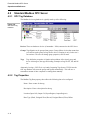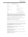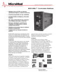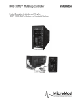
1
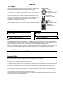
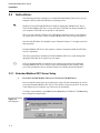
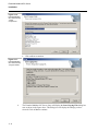
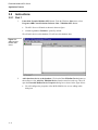
Extended Modbus OPC Server ABB Inc. User’s Guide ABB Inc. The Company ABB Inc. is an established world force in the design and manufacture of instrumentation for industrial process control, flow measurement, gas and liquid analysis and environmental applications. As a part of ABB, a world leader in process automation technology, we offer customers application expertise, service and support worldwide. We are committed to teamwork, high quality manufacturing, advanced technology and unrivaled service and support. The quality, accuracy and performance of the Company's products result from over 100 years experience, combined with a continuous program of innovative design and development to incorporate the latest technology. The NAMAS Calibration Laboratory No. 0255(B) is just one of the ten flow calibration plants operated by the Company, and is indicative of ABB Inc.'s dedication to quality and accuracy. BS EN ISO 9001 St Neots Certificate No. Q5907 Stonehouse Certificate No. FM 21106 ISO 9001 Rochester, USA Certificate No. AQ-8618 EN 29001 (ISO 9001) Lenno, Italy Certificate No. 90/90A Stonehouse Certificate No. 0255 Use of Instructions ∆ ! Warning. An instruction that draws attention to the risk of injury or death. Caution. An instruction that draws attention to the risk of the product, process or surroundings. i Note. Clarification of an instruction or additional information. Information. Further reference for more detailed information or technical details. Although Warning hazards are related to personal injury, and Caution hazards are associated with equipment or property damage, it must be understood that operation of damaged equipment could, under certain operational conditions, result in degraded process system performance leading to personal injury or death. Therefore, comply fully with all Warning and Caution notices. Information in this manual is intended only to assist our customers in the efficient operation of our equipment. Use of this manual for any other purpose is specifically prohibited and its contents are not to be reproduced in full or part without prior approval of ABB Inc.. Licensing, Trademarks and Copyrights MODCELL, MOD 30 and MOD 30ML are trademarks of ASEA Brown Boveri, Inc. MODBUS is a trademark of Modicon Inc. Health and Safety To ensure that our products are safe and without risk to health, the following points must be noted: 1. The relevant sections of these instructions must be read carefully before proceeding. 2. Warning Labels on containers and packages must be observed. 3. Installation, operation, maintenance and servicing must only be carried out by suitably trained personnel and in accordance with the information given or injury or death could result. 4. Normal safety procedures must be taken to avoid the possibility of an accident occurring when operating in conditions of high pressure and/or temperature. 5. Chemicals must be stored away from heat, protected from temperature extremes and powders kept dry. Normal safe handling procedures must be used. 6. When disposing of chemicals, ensure that no two chemicals are mixed. Safety advice concerning the use of the equipment described in this manual may be obtained from the Company address on the back cover, together with servicing and spares information. 1 1.1 Introduction Introduction Extended Modbus OPC Server is an Industrial IT enabled software product. It is an OPC Foundation compliant server application (serial communications device interface) that allows hardware devices to communicate with OPC Clients such as ABB Operate IT Products and other software manufacturer's HSI packages like ICONICS’ Genesis32, Intellution's FIX Dynamics and similar packages from Wonderware, CI Technologies and others. For client software packages that are not OPC compliant, the server also supports dynamic data entry (DDE) type links. ViZapp, Visual Application Designer, is also an OPC Client that can use this OPC server to communicate with the devices it configures. The OPC server handles the reading and writing of the device data. See Overview of OPC based configuration for steps involved in configuring the client and server. This OPC server supports MODCELL and MOD 30ML devices using Extended Modbus as well as generic Modbus devices such as the MODCELL 2050 and the Commander controllers and recorders including: C100, C200, C250, C300, C310, C500, C1900, L150, L160, PR100, PR250, and MR250. The server is used to build the tag database that contains information about the tags such as tag name, address, device (instrument) from which they are coming and communication port settings. Any OPC Client application, such as OPC based HMI Software, can plug and play with this and present the data to the user. An OPC Client is included in the ABB Extended Modbus OPC Server. This monitor client is useful for viewing live data and determining if configured tags are receiving correct data from the hardware. 1.2 Definitions 1.2.1 Standard Modbus Protocol Standard MODBUS supports single-register, 16-bit integer values. ABB Commander series instruments and the Modcell 2050 use this protocol. Modcell and MOD30ML floating-point data may be converted to this format with ML blocks. For maximum resolution, specify an actual engineering-unit range in the ML block. If the engineering range is greater than 65535, a scaled range must be selected. Some standard MODBUS drivers may be capable of reading floating-point data, using a 32-bit two-register format. 1-1 Training Manual Introduction 1.2.2 Extended Modbus Protocol Modcell and MOD30ML devices support an extended protocol, in addition to standard MODBUS RTU. XModbus OPC Server supports these extended features allowing additional data types, automatic scaling and entry of user defined tag names. The extended protocol also supports ViZapp Debug and Status displays, which may be used to provide extended diagnostic and event information. Note that the 2-wire RS-485 module does not support these features. When using Extended MODBUS, special interface files are created when compiling the instrument database. These files provide automatic configuration of host poll records, significantly reducing engineering time. A MIF file is used for XModbus OPC Server and FIX software. PC-30 and GFW use a TIF file. With Extended MODBUS, user-friendly alias names are given to points in the Configured List. In the host software, these alias names are used instead of register addresses. 1.2.3 Built-in OPC Client An OPC Client application is built-in with the Extended Modbus OPC Server for monitoring and testing your Server’s configuration. It is this part of the OPC application that collects data received by the OPC Server and presents to the user. The data presented by the OPC Client is live. OPC Client is useful for testing the communication between the devices and the OPC Server. It can also be used for testing other 3rd party OPC applications connected to the server. 1-2 2 2.1 Installation Objectives This chapter explains the installation procedure for the Extended Modbus OPC Server. 2.2 System requirements: For running the Extended Modbus OPC Server, you need the following computer configuration and software installed: • Pentium 300 MHz or faster processor with 64 MB RAM. • At least 100 MB of available hard disk space. • CD ROM Drive (at least 4 speed, higher speed recommended) • A SVGA monitor or better. • Windows 2000 or Windows XP or Microsoft Windows NT 4.0. Service Release 4.0 or higher with Service Pack 5 or higher or Microsoft Windows 98 Second Edition or Microsoft Windows 95 B Release with DCOM • A mouse or other compatible pointing device. 2-1 Extended Modbus OPC Server Installation 2.3 Instructions: The following procedure explains how to install Extended Modbus OPC Server on your computer. Start your Microsoft Windows operating system. Windows 95 needs DCOM (Distributed COM) for running the XModbus OPC Server. The Extended Modbus OPC Server setup will detect if DCOM was already installed on your computer. If DCOM was not present, it will install it. This is an issue with only Windows 95. If DCOM was already present in your Windows 95 system and is of a lower version, Extended Modbus OPC Server setup will update it. Note also that DCOM is also installed as part of Internet Explorer 5.0 or higher and some other programs. Extended Modbus OPC Server also requires a software component called the OPC Data Access Components. The above programs are installed by Extended Modbus OPC Server in the background during the Setup and do not require any user inputs. Close all applications that are running in your computer currently before starting the Extended Modbus OPC Server setup. If a previous installation of the software exists, you will be prompted to choose an option from the list: Modify, Repair and Remove. 2.3.1 Extended Modbus OPC Server Setup 1. Insert the Extended Modbus OPC Server CD into the CD-ROM drive. In most computers where auto run is enabled, the setup will start automatically as soon as you put the Extended Modbus OPC Server CD in the drive and close the drive. If auto run is not enabled in your computer you will need to run it manually. To run the setup manually, select Run from the Start Menu of Windows. The Run dialog box will appear as shown below: Figure 2 .1. Run dialog box 2-2 Extended Modbus OPC Server Installation Type D:\SETUP.EXE or E:\SETUP.EXE, (CD DriveLetter:\Setup.exe depending on the letter you use for the CD-ROM drive) and click on OK or press ENTER. 2. The Extended Modbus OPC Server Setup introductory screen displays briefly while installation is initiating. Figure 2 .2. Extended Modbus OPC Server Setup 3. The following message will be displayed if you are installing the Extended Modbus OPC Server under Windows 95. Figure 2 .3. Extended Modbus OPC Server Setup The features that are not supported under Windows 95 and 98 are: • Visual properties such as color and texture of the blocks in the function block diagram. • Memory management – limitation on the number of documents you can have in a project or workspace. This is due to the limitations in the operating system. The setup will display the Welcome dialog box as shown below. Click on Next to continue. 2-3 Extended Modbus OPC Server Installation Figure 2 .4. Extended Modbus OPC Server Setup Welcome 4. ABB Software License Agreement will be displayed next and will display the legal information about using the Extended Modbus OPC Server Software. Click on Yes if you accept the agreement. Clicking on No will terminate the Setup. Refer to the next figure. ABB Software License Agreement is a legal document. Read it carefully before clicking on Yes. Figure 2 .5. Extended Modbus OPC Server Setup –ABB license Agreement An Information dialog box will be displayed next as shown in the next figure: 2-4 Extended Modbus OPC Server Installation Figure 2 .6. Extended Modbus OPC Server Setup –Information 5. Enter User Information: The User Information dialog box will be displayed next as shown below. Type your name, company name and the serial number. This serial number can be found on the CD case or the Extended Modbus OPC Server package you received. Click on Next to continue. Figure 2 .7. Extended Modbus OPC Server Setup –Destination Location 6. The Choose Destination Location dialog box will be displayed next as shown in the next figure. We will choose the default location for the setup. Click on Next to continue. 2-5 Extended Modbus OPC Server Installation If you want to install Extended Modbus OPC Server onto a different folder, click on the Browse button to open the Choose Folder dialog box and then browse to the desired folder or create a new folder by typing its name in the Path field. • Click on OK to continue. Figure 2 .8. Extended Modbus OPC Server Setup –Choose Destination 7. Select Components for installation: The Extended Modbus OPC Server Software package consists of the main software and a few options. You can choose the options at the time of setup. By default, all available options are selected, except for On-line Documentation. These options will be displayed as check boxes on the dialog box. See the next figure for example. This dialog box also shows the space required on the hard disk to install the selected options and the total free space on the disk. Accept the defaults and then click on Next to continue. 2-6 Extended Modbus OPC Server Installation Figure 2 .9. Extended Modbus OPC Server Setup –Select Components 8. Choose the Program Folder: The Extended Modbus OPC Server setup will also create a program folder and will create program shortcuts inside that folder. You can use these shortcuts to start the programs. The default program folder that will be automatically created will be: ABB Control Solutions Software Suite. If you want to create a new program folder you can type its name in the Program Folders field on this dialog box. If you want to use one of the existing program folders, you can choose it from the Existing Folders list box on this dialog box by clicking on it. 2-7 Extended Modbus OPC Server Installation Figure 2 .10. Extended Modbus OPC Server Setup –Select Components • Click on Next to continue. Figure 2 .11. Extended Modbus OPC Server Setup –Program Folder 9. 2-8 The Extended Modbus OPC Server Setup will display the Start Copying Files dialog box next as shown in the figure above. This dialog box will display the settings you have selected. Click on Next to continue. Extended Modbus OPC Server Installation Figure 2 .12. Extended Modbus OPC Server Setup 10. The setup will start now and will display a progress bar as shown above. After the Setup copied all the required files, the following Information box will be displayed. The Extended Modbus OPC Server CD contains all the technical documentation in Adobe PDF format. If your system does not have Adobe Acrobat Reader installed already, you can install it from the CD after the Extended Modbus OPC Server Setup completes. Figure 2 .13. Extended Modbus OPC Server Setup 11. Extended Modbus OPC Server Setup will register all the software components with the Windows registry and a message box as shown below will be displayed. Figure 2 .14. Extended Modbus OPC Server Setup –HardLock Driver 12. After the files are registered, the setup will be complete and a dialog box as shown in the next figure will be displayed. 2-9 Extended Modbus OPC Server Installation Figure 2 .15. Extended Modbus OPC Server Setup –Setup Complete 2 - 10 • Click on Finish to complete the installation. • If the setup had to overwrite any DLLs that were open in the system at the time of Setup, then you will need to restart the computer for the changes to be effective. You can opt to restart your computer at a later time. 3 3.1 Application Tutorial Objectives In this lab, we will configure an Extended Modbus OPC Server database and add a device to it. We will use this database to download the PIDLAB Strategy from the previous lab to the MOD 30ML instrument. We will also populate the OPC database with tags using the Modbus Interface File (.MIF) created in the previous lab and monitor the data by reading them from the instrument using the built-in OPC Client of the Extended Modbus OPC Server. After completing this lab you should be able to: • Configure a Extended Modbus OPC database • Download the Instrument document (strategy) • View the signals using the built-in OPC Client 3-1 Extended Modbus OPC Server Application Tutorial 3.2 Instructions 3.2.1 Part 1 1. Launch the Extended Modbus OPC Server: From the Windows Start menu, select Programs-ABB Control Solutions Software Suite - XModbus OPC Server. • The OPC Server will launch as shown in the next figure. • A blank tag database Untitled is opened by default. We will add a device to this database. We will save this database later. Figure 3 .1. ABB Extended Modbus OPC Server 2. Add a hardware device to the database: Click on the New XModbus Device button on the toolbar or select Add-New XModbus Device from the menu bar at the top. This will open the Extended Modbus Device Properties dialog box as shown in the figure below: • 3-2 We will configure the properties of the MOD 30ML device we are adding in this dialog box. Extended Modbus OPC Server Application Tutorial Figure 3 .2. Add new Extended Modbus Device • Type the name MOD30ML in the Name field (the name is user-configurable and can be anything!). • Select the serial communication port of the computer to which the MOD 30ML is connected, in the Port field. Click on the down arrow in this field to show the dropdown menu and then select the port. (COM1 for example). • Type the instrument’s Modbus address in the address field. • Leave the Timeout in the default value of 1000 ms. Timeout value in ms is the time for which the OPC server tries to re-establish communication with the device in the case of a communication failure. 3. Configure the serial port for the communication: Click on the Edit – Ports button on this dialog box. The Port Properties dialog box will be displayed as shown below: 3-3 Extended Modbus OPC Server Application Tutorial Figure 3 .3. Port Properties • Select the COMM port from the drop-down menu in the Port field and then enable it by checking the box next to the Enable field. • Choose the Baud Rate, Parity, Flow Control, Data bits and Stop bits from this dialog box. Make sure these entries match the settings of the instrument. • Click on OK to complete the Port configuration. • The Extended Modbus Device Properties dialog box will redisplay with the port number. Leave other fields on this dialog box at their default values. • Click on OK. The added device will be displayed in the Device Tree on the left frame as shown in the next figure: Figure 3 .4. ABB Extended Modbus OPC Server database 4. 3-4 Save the database: The OPC tag database can be save as a file with an extension .MOPC. • Select File – Save from the menu bar. Refer to the following figure. • The Save As dialog box will be displayed next as shown below: • Choose the same folder where you have saved the PIDLAB database for saving this file and then type a name for the OPC tag database file in the File name field. Extended Modbus OPC Server Application Tutorial Figure 3 .5. File – Save As • Click on the Save button to save the file. The Title bar of the OPC Server will redisplay with the saved file name. • You can now either close the Extended Modbus OPC Server application by selecting File – Exit from the menu bar at the top or minimize it. 3-5 Extended Modbus OPC Server Application Tutorial 3.2.2 Part 2 – Downloading database from ViZapp 5. Run the Vizapp Application and open your workspace document. Open your instrument document on the right frame. Select Instrument – Download from the menu bar at the top. • The Communication Setup dialog box will be displayed as shown below: • Click on the Browse button next to the Server name field to browse the OPC Servers registered in the system. • The Select OPC Server dialog box will be displayed as shown in the next figure: • Look at the Available Servers box at the bottom. The ABB Xmodbus Server should be listed there. Figure 3 .6. Communication Setup The VizApp Setup you did in Lab2 installed the Xmodbus OPC Server and registered it to the Windows registry. If you have other OPC Servers registered in the system, you will see them also in the Available Servers list. 3-6 Extended Modbus OPC Server Application Tutorial Figure 3 .7. Select OPC Server • Click on ABB.Xmodbus item to select it. It should now be displayed in the Server Name field. Click on OK. • The Communication Setup dialog box will redisplay with ABB.Xmodbus in the Server Name field as shown below: Figure 3 .8. Communication Setup 6. Select the Device: Click on the Browse button next to the Device Name field. 3-7 Extended Modbus OPC Server Application Tutorial • The Select Device dialog box will display as shown below next. You will also notice the Xmodbus OPC Server application started automatically with the OPC database file you last saved. • This Select Device dialog box will show the name of the device you added to the OPC Database in Part A of this lab. Select the device and then click on OK. Figure 3 .9. Select Device The devices in the Select Device list are populated from the last saved/opened Xmodbus OPC Server database file • 7. The Communication dialog box will redisplay as shown below with the name of the device in the Device Name field. Populate OPC Server tag database with attributes selected in the Modbus Interface File (.MIF file): • Refer to the following display. • Check the box Populate ViZapp and Server Tag lists by clicking on it and then select the Modbus Interface File PIDLAB from the Available MIF Files list at he bottom. By doing this you can populate the OPC Server tag database with tags that will be automatically created from the attributes defined in the MIF file (attributes added to your Configured List blocks in the strategy). This will save a tremendous amount of engineering time as you do not have to create each tag manually. This will also create a list of Tags in the VizApp Configurator automatically. These tags can be used to add graphic objects to your instrument documents and display documents. 3-8 Extended Modbus OPC Server Application Tutorial Figure 3 .10. Communication Setup • Click on OK on this dialog box. The Download Status Indicator will display as shown below if the communication with the instrument was established. If there was no communication, you will get error message boxes. • After successful download, the following message box saying “Download completed without error” will be displayed. Click on OK. • The OPC Server application will also be closed automatically if it was started by VizApp for downloading. Figure 3 .11. Downloading Figure 3 .12. Download 3-9 Extended Modbus OPC Server Application Tutorial 3.2.3 Part 3 – ABB Xmodbus OPC Client 8. Launch the XModbus OPC Server Application if it was not running already. It will be launched with your last saved database PidLab.MOPC as shown below: Figure 3 .13. OPC Server database with tags • Do you notice that the OPC database is populated with tags from the MIF file automatically? Also notice that the tags are shown with alias names. • Select the device (MOD30ML1) and right-click on it. Select Properties from the resulting menu. • This will display the Device Properties dialog as shown below: • This dialog gives details about the MIF file in addition to the device details. Important information about the MIF file are: Figure 3 .14. Device Properties • MIF file name and location. • Time-stamp • Number of elements / tags. By clicking on the button next to the MIF File field, you can choose a different MIF file to attach to this device. Do not do that for this lab as the MIF file is already used to populate the tags. 3 - 10 Extended Modbus OPC Server Application Tutorial Figure 3 .15. Device Properties • Click on Cancel on this dialog. Figure 3 .16. OPC Live Data 9. View Live data by starting the built-in OPC client application: • Select View - Monitor from the menu bar at the top. This will start the built-in OPC client and show live data from the instrument in the Value column of the OPC Server application. Refer to the figure above. • The live data is read-only as this OPC client application and is mainly used for testing the function of the OPC Server and the communication between the hardware devices and the OPC Server tag database. It does not allow writing of the same. 3 - 11 Extended Modbus OPC Server Application Tutorial 10. View more details of the tags: Double-click on FICPVI. This will display further properties of that tag as shown below: Figure 3 .17. Tag properties 3 - 12 • The above dialog displays the LSP, High and Low ranges, Read/Write of the tag. • Click on the Close button to close this dialog. Operation and Reference 4 4.1 Extended Modbus OPC Server 4.1.1 OPC Tag Database The database is typically made up of the following: Devices: These are hardware devices (MODCELL / MOD 30ML) connected to the OPC Server. Groups: Tags/Signals can be grouped together into groups. Groups follow a device that means that you can make groups of tags from a device. In the Extended Modbus OPC database, the grouping will be based on the grouping in the CL block in the instrument database database. Each block in the database will be one group and will have the selected attributes of that block. For example, if you have a block named FIC-100, the group will be called FIC-100 and the signals like PVI, SP, OP etc, will be tags belonging to that group. Blocks inside a compound will be grouped into a bigger group with name as the compound name. Grouping is only for the user’s convenience. If aliases are configured in the CL block for tags, then the tags will be attached to the devices directly (at the root level). Tags: Tags define the properties of signals such as address of the signal, group and device it belongs to, data type and scaling. Examples of tags are PVI, SP, and OP etc, of a PID block. Figure 4 .1. OPC Server Tag database 4-1 Extended Modbus OPC Server Operation and Reference Having a .MIF file is very handy. Connecting the MIF file to a device in the OPC tag database will create the groups and signals automatically. This will save a tremendous amount of time compared to creating them manually. In the case of generic Modbus devices such as ABB Commander series instruments, you have to create the groups and tags manually and should define their properties. Refer to the Standard Modbus section of this chapter. 4.1.2 Extended Modbus Device Properties Configure the properties of the MODCELL or MOD 30ML device in this dialog. Figure 4 .2. Extended Modbus Device Properties Name: Type a name for the device – you can type any name in the Name field. Port: Select the serial communication port of the computer to which the device is connected to in the Port field. Click on the down arrow in this field to show the dropdown menu and then select the port (For example, COM1). Timeout: Timeout value in ms is the time for which the OPC server tries to reestablish communication with the device in the case of a communication failure. The default value of 1000 ms should not need to be changed. Address: Type the instrument’s Modbus address in the address field. 4-2 Extended Modbus OPC Server Operation and Reference Interface File: MIF file - Choose the Modbus Interface file for this device: To choose a .MIF file, 1. Click on the button next to the MIF File field on this dialog box. This will display a list of Modbus Interface files available. 2. Choose your working directory in this dialog box and then select your MIF file inside that directory by clicking on it. The selected file will be displayed in the File Name field at he bottom. 3. Click on Open to accept the MIF file. The dialog box will display the Version of the MIF file, its Time Stamp (time at which the file was created or last), Instrument ID, Number lines in the MIF file and most importantly, the Number Elements (number of items or tags from the device) 4. Click on OK to complete the device configuration. Note: This field will be automatically filled in by ViZapp, if the "Populate ViZapp and OPC Server tag lists" box is checked when downloading. Figure 4 .3. ViZapp Communication Setup Simulate I/O: The OPC Server does not access the device in Simulate mode. When checked, no communication takes place and I/O values are generated randomly. 4-3 Extended Modbus OPC Server Operation and Reference 4.1.3 Serial Port Configuration Configure the serial port for the communication: Menu item Edit – Ports displays the communication port settings as shown below: Figure 4 .4. Port Properties 4-4 • Select the COMM port from the drop-down menu in the Port field and then enable it by checking the box next to the Enable field. • Choose the Baud Rate, Parity, Flow Control, Data bits and Stop bits from this dialog box. Make sure these entries match the settings of the instrument. • Click on OK to complete the Port configuration. • The Extended Modbus Device Properties dialog box will redisplay with the port number. Leave other fields on this dialog box at their default values. • Click on OK. The added device will be displayed in the Device Tree on the left frame as shown in the next figure: Extended Modbus OPC Server Operation and Reference 4.1.4 Tag Data The XModbus Tag Data property sheet shows the following configured data: Figure 4 .5. Tag properties LSP (Logical Source Pointer) - a mnemonic and associated path to a device block attribute High Range configured value Low Range configured value Read/Write configured value Foreground (is checked if enabled) Offset address Bit Position Foreground Quality (is checked if enabled) Offset address Bit Position Fields except for enabling the Foreground ad Foreground Quality are not configurable in this dialog box. 4-5 Extended Modbus OPC Server Operation and Reference 4.1.5 Saving the OPC Server Tag database: The OPC tag database can be save as a file with an extension. MOPC. • Menu item File – Save will save the OPC Tag database. • The Save As dialog box will be displayed next as shown below: • Choose the same folder where you have saved the PIDLAB database for saving this file and then type a name for the OPC tag database file in the File name field. • Click on the Save button to save the file. The Title bar of the OPC Server will redisplay with the saved file name. Figure 4 .6. File – Save As 4.1.6 ABB XModbus OPC Client Menu item View – Monitor activates the built-in OPC Client application: Figure 4 .7. OPC Live Data • 4-6 Live data values from the instrument will be displayed in the Value column of the OPC Server application. Extended Modbus OPC Server Operation and Reference • The live data is read-only as this OPC client application and is mainly used for testing the function of the OPC Server and the communication between the hardware devices and the OPC Server tag database. It does not allow writing of the same. 4-7 Extended Modbus OPC Server Operation and Reference 4.2 Standard Modbus OPC Server 4.2.1 OPC Tag Database The Modbus device tag database is typically made up of the following: Figure 4 .8. OPC Server Tag Database Devices: These are hardware devices (Commander / 2050) connected to the OPC Server. Groups: Tags/Signals can be grouped into groups. Groups follow devices that means that you can have make groups of tags from a device. Grouping is only for the user’s convenience. The user can change group properties, such as name. Tags: Tags define the properties of signals such as address of the signal, group and device it belongs to, data type and scaling. Examples of tags are PV, SP, and OP etc. Alternately, having a .CSV file is very handy. Importing Tags from a CSV file into the OPC tag database will create the groups and signals automatically. This will save a tremendous amount of time compared to creating them manually. 4.2.2 Tag Properties The Modbus Tag Data property sheet allows the following data to be configured: Name: Enter a name for the tag. Description: Enter a description for the tag. Location (Input Coil, Output Coil, Input Register, Output Register) Data Type (Word, Unsigned Word, Dword, Unsigned Dword, Float, Dfloat. 4-8 Extended Modbus OPC Server Operation and Reference Data Type Number of Registers Limits Word 1 32768 to 32767 Unsigned Word 1 0 to 65535 DWord 2 -2,147,483,648 to 2,147,483,647 Unsigned DWord 2 0 to 4,294,967,295 Float 2 +/- 3.4 E38 (7 Significant digits) DFloat 4 +/- 1.4 E308 (15 Significant digits) New Read: Check this box to make this location the start of a read message. This may be required to prevent the server from trying to read through invalid addresses (40100) or from trying to read too many locations in one message (see table below). Reference IBMODBUS-RTU page 21 or IB-23G600 Logic Book 1 Section 4.3.1 page 20. This feature may not be required after configuring parameters in the Device properties. Scaling: Check to enable scaling and then select the type of scaling desired from the Style pull down. Use the Settings button to define a scaling style. Simulation signal: Select from Sine, Ramp or Random The maximum number of Modbus values MODCELL and MOD 30ML can read or write are: Read Coil Status discrete points from (00001 - 00099) (00101 - 00199) (00201 - 00299) (00301 - 00399) (00401 - 00499) Read Input Status discrete points from (10001 - 10099) (10101 - 10199) (10201 - 10299) (10301 - 10399) (10401 - 10499). Maximum Values - 99 points Read holding registers (no ASCII or Hex) from (40001 - 40099) (40101 - 40199) (40201 - 40299) (40301 - 40399) (40401 - 40499) Maximum Values - 32 registers Read holding registers (any data type) from (41001 - 41999) (42001 - 42999) (43001 43999) (44001 - 44999) (45001 - 45999) Maximum Values - 125 registers Read input registers (no ASCII or Hex) from (30001 - 30099) (30101 - 30199) (30201 30299) (30301 - 30399) (30401 - 30499) Maximum Values - 32 registers 4-9 Extended Modbus OPC Server Operation and Reference Read input registers (any data type) from (31001 - 31999) (32001 - 32999) (33001 33999) (34001 - 34999) (35001 - 35999) Maximum Values - 125 registers 4.2.3 Scaling Use this menu to define the conversion of raw data into engineering units and define that as a New Style. You may also delete any styles no longer needed. To add a new style: 1. Select an existing style to base the new one on if available. 2. In the new style menu enter a unique name and check the initialize from box if it is to be based on the previously selected style or leave it unchecked to use the default style scaling data. 3. Enter the following data as appropriate. Units Raw Minimum value Raw Maximum value Scaled Units Minimum value Scaled Units Minimum value Conversion selection Linear Square Root 4.2.4 Scaling Analog Values for Commander Series Instruments The first Commander instruments to support MODBUS handled scaling of analog values in a different way than later instruments. The ABB C200, C300, C1900 and PR100 instruments use a 12-bit register with a raw range of 0 to 4095. The host must scale the value to obtain the desired engineering unit value. Newer models, such as the ABB C100, C150, C250, C500 and PR250 instruments, place an engineering unit value into one or two 16-bit registers. If two registers are used, the data type is considered a long integer. Values are represented as positive or negative integers without a decimal point. If a decimal point is used in the instrument, additional scaling must be performed at the host. 4 - 10 Extended Modbus OPC Server Operation and Reference 4.2.5 Import CSV A comma separated file, having the following format. A CSV file can be constructed in a text editor or in a spreadsheet program and exported as CSV. Note that the lines starting with "#" are comment lines. Each line following the comments represents a tag. A tag line consists of the following data: Device.Group.Tag Name, where the group name is optional Coil/Register Address, Data Type, New Read, Tag Description, Square Root, Initial Data, Engineering Low, Engineering High, Engineering Units, Raw Low, Raw High Only device, tag, address and data type are required for import. Other fields are optional. 4 - 11 Extended Modbus OPC Server Operation and Reference 4.2.6 SAMPLE CSV FILE # ABB Instrumentation, Extended Modbus OPC Server # Monday, August 23, 1999, 12:24 # Device.Tag or,Coil/Register,Data,New,Tag,Sqr.,Initial,Eng.,Eng.,Eng.,Raw,Raw # Device.Group.Tag,Address,Type,Read,Description,Root,Data,Low,High,Units,Low,High C100.ALM1,6,Bool,0,"Alarm State 1" C100.ALM2,8,Bool,0,"Alarm State 2" C100.CMode,30,Bool,0,"Auto (0) / Manual (1)" C100.DER,40027,Word,0,"Derivative Time" C100.DI,14,Bool,0,"Digital Input" C100.DO,15,Bool,0,"Digital Output" C100.INT,40026,Word,0,"Integral Time" C100.OP,40014,Word,0,"Control Output" C100.PB,40025,Word,0,"Proportional Band" C100.PV,40011,DWord,0,"Process Variable Input" C100.PVDP,40003,Word,0,"PV Decimal Position" C100.SP,40013,Word,0,"Control Setpoint" DataTypes.IC1,10001,Bool,0,"Input Status is Read Only" DataTypes.IC2,10002,Bool,0, DataTypes.IR1Word,30001,Word,0,"Raw 0 to 65535, EU 0 to 100%",0,0.000000,0.000000,100.000000,%,0.000000,65535.000000 DataTypes.IR2DWord,30002,DWord,0,"DWord uses 2 consecutive registers" DataTypes.IR3Float,30004,Float,0,"Float uses 2 consecutive registers" DataTypes.IR4WordLiveZero,30006,Word,0,"Raw -32768 to 32767, Eng 0 to 100%",0,0.000000,0.000000,100.000000,%,-32768.000000,32767.000000 DataTypes.IR5WordLiveZero,30007,Word,0,"Raw -32768 to 32767, Eng -10 to 10 in. H2O",1,0.000000,-10.000000,10.000000,in. H2O,-32768.000000,32767.000000 DataTypes.OC1,1,Bool,0,"Coils Status is Read/Write" DataTypes.OC2,2,Bool,0, DataTypes.OR1Word,40001,Word,0,"Holding Registers are Read/Write" DataTypes.OR2DWord,40002,DWord,0,"DWord uses 2 consecutive registers" DataTypes.OR3Float,40004,Float,0, DataTypes.IR6Word,30008,Word,0,"Input Registers are Read Only" MOD30ML-StdModbus.Date,40006,Word,0,"Date - Packed into 16 bits" MOD30ML-StdModbus.msTime,40007,Word,0,"Millisecond Time - Scaled in ML Block" MOD30ML-StdModbus.Analogs.Count,40002,Word,0,"Count", 0,0.000000,0.000000,100.000000,%,0.000000,65535.000000 MOD30ML-StdModbus.Analogs.Float1,40001,Word,0,"Float Converted to Word",0,0.000000,0.000000,100.000000,%,0.000000,65535.000000 MOD30ML-StdModbus.Analogs.Float2,41011,Float,0,"2-Register ieee Floating Point" MOD30ML-StdModbus.Analogs.LState,40004,Word,0,"Long State",0,0.000000,0.000000,100.000000,%,0.000000,65535.000000 MOD30ML-StdModbus.Analogs.SState,40005,Word,0,"Short State",0,0.000000,0.000000,100.000000,%,0.000000,65535.000000 MOD30ML-StdModbus.Discretes.Discrete,1,Bool,0,"Discrete" MOD30ML-StdModbus.Discretes.Mom,2,Bool,0,"Momemtary Discrete" 4 - 12 Extended Modbus OPC Server Operation and Reference 4.2.7 CSV Import Options When adding tags from a CSV file that may be in conflict with existing tags, you are given the choice of: • Adding new tags contained in the CSV file WITHOUT changing existing tags. • Adding new tags contained in the CSV file and REPLACE tags that already exist. • REMOVE existing groups and tags, then add tags contained in the CSV file. If checked, the Display the log file will display the file "Import.log" which contains the status of importing the CSV file. 4.2.8 Export CSV A comma separated file that can be used to document the servers tag database. Note that the first two lines are comment lines. Each line following the comments represents a tag. A tag line consists of the following data: • Device.Group.Tag Name, where the group name is optional • Coil/Register Aaddress, • Data Type, • New Read, • Tag Description, • Square Root, • Initial Data, • Engineering Low, • Engineering High, • Engineering Units, • Raw Low, • Raw High 4 - 13 Extended Modbus OPC Server Operation and Reference 4.3 Dynamic Data Entry (DDE) Type Links The Extended Modbus OPC Server supports DDE (Dynamic Data Exchange) for serving data to DDE Client applications such as Microsoft Excel. The typical reference for DDE connections is: Program|Topic!Point The character between Program and Topic is called a Pipe, the dashed vertical line character on the keyboard. An exclamation point is used between the Topic and Point. Refer your application's documentation for using DDE. The following example is for Microsoft Excel: =xmbopc|'C100'!OP In this example, xmbopc is the executable filename of the OPC Server, 'C100' the name that was given to the device in the server configuration, and OP is the name given to holding register 40014. Excel automatically enclosed C100 in quotes. The rule is that if a Topic or Name contains spaces or special characters, it must be enclosed in quotes. After entering the valid reference, Excel asks to start the application if it is not already running. The #REF! Error value occurs when a cell reference is not valid. In this example, this will occur if the xmbopc application is not found, or if the device name or point name is wrong. 4 - 14 PRODUCTS AND SERVICING A Comprehensive Instrumentation Range Sensors, transmitters and related instruments for flow, temperature, pressure, level and other process variables Flowmeters electromagnetic, ultrasonic, turbine, differential pressure, Wedge, rotary shunt, coriolis, vortex. Differential Pressure transmitters Smart, electronic and pneumatic. Temperature sensors and transmitters, fiber optic systems. Pressure transmitters Level sensors and controllers. Tank gauging systems Cable-length measuring systems Indicators, recorders, controllers and process management systems Recorders circular and strip-chart types - single and multi-point - for temperature, pressure, flow and many other process measurements. Controllers digital display, electronic. Discrete single-loop and multi-loop controllers which can be linked to a common display station, process computer or personal computer. Liquid and gas monitors and analyzers for on-line and laboratory applications Sensors pH, redox, selective ion, conductivity and dissolved oxygen. Monitors and Analyzers for water quality monitoring in environmental and power generation and general industrial applications. Packaged analytical instrumentation laboratories Gas analyzers Zirconia, paramagnetic, infrared, thermal conductivity. Servicing ABB Inc. provides a comprehensive after sales service via a Worldwide Service Organization. Contact one of the following offices for details on your nearest Service and Repair Center. United Kingdom London ABB Instrumentation Limited Tel: (1480) 470781 FAX: (1480) 470787 United States of America ABB Inc. 125 E. County Line Rd Warminster, PA 18974-4995 Tel: (215) 674-6000 Fax: (215) 273-7183 140 Mushroom Blvd Rochester, NY 14623-3204 Tel: (585) 292-6050 Fax: (585) 273-6969 Italy Lenno (Como) ABB Kent-Taylor SpA Tel: (0344) 58111 Fax: (0344) 56278 The Company’s policy is one of continuous product improvement and the right is reserved to modify specifications contained herein without notice. ©2002 ABB Inc. ABB Instrumentation Ltd. St. Neots Cambs. England, PE19 3EU Tel: (01480) 475321 Fax: (01480) 217948 ABB Inc. Warminster, PA USA Rochester, NY USA Tel: (215) 674 6000 / (585) 292-6050 Fax:(215) 674 7183 / (585) 273-6969 IB-XMBOPC-REF, Issue 1 ABB Kent-Taylor SpA 22016 Lenno Como, Italy Tel: (0344) 58111 Fax: (0344) 56278 09/02