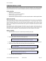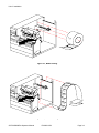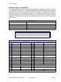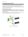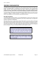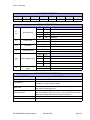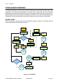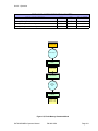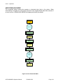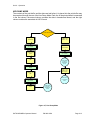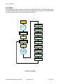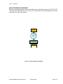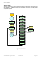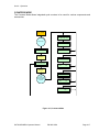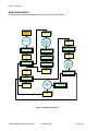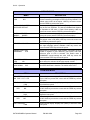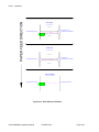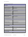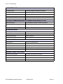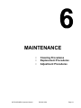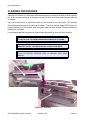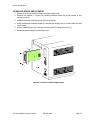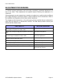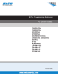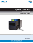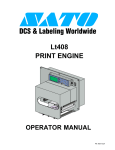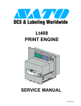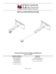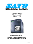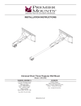
1
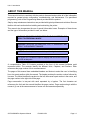
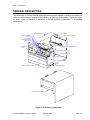
M5900RVe
Direct Thermal Printer
OPERATOR MANUAL
PN 9001125A
SATO America, Inc.
10350A Nations Ford Road
Charlotte, NC 28273
Main Phone: (704) 644.1650
Technical Support Hotline: (704) 644.1660
Technical Support Fax: (707) 644.1661
E-Mail: [email protected]
[email protected]
www.satoamerica.com
WARNING
THE EQUIPMENT REFERENCED IN THIS DOCUMENT COMPLIES WITH THE REQUIREMENTS IN
PART 15 OF FCC RULES FOR A CLASS B COMPUTING DEVICE. OPERATION OF THIS EQUIPMENT
IN A RESIDENTIAL AREA MAY CAUSE UNACCEPTABLE INTERFERENCE TO RADIO AND TV
RECEPTION.
TABLE OF CONTENTS
INTRODUCTION
About This Manual
General Description
Primary Components
Control Features
Switches
Connection Ports
1-2
1-3
1-3
1-5
1-5
1-5
TECHNICAL DATA
Physical Characteristics
Power
Enviromental
Print
Media
Sensing
Interface Modules
Processing
Character Font Capabilities
Barcode Capabilities
Regulatory Approvals
2-2
2-2
2-2
2-2
2-3
2-2
2-3
2-3
2-3
2-4
2-4
INSTALLATION
Unpacking & Parts Identification
Printer Installation
Site Location
Media Selection
Media Loading
Interface Selection
RS232 Serial Interface
IEEE1284 Parallel Interface
Universal Serial BUS (USB) Adapter
Local Area Network (LAN) Ethernet
802.11B Wireless
Receive Buffer
ACK/NAK Protocol
Accessories Installation
Interface Module
PN 9001125A
3-2
3-3
3-3
3-3
3-3
3-5
3-5
3-7
3-8
3-8
3-8
3-9
3-9
3-10
3-10
OPERATION
Printer Configuration
Dip Switch Panels
Configuration Modes
Normal Mode
Test Print Mode
Advanced Mode
Default Settings Mode
Flash Memory Download Mode
User Download Mode
Hex Dump Mode
Card Mode
Non-Standard Clear Mode
Service Mode
Counters Mode
Maintenance Mode
Screen Identification
Operational Adjustments
Print
Offset
Pitch
Print Reference Position
Sensor & Accessory Location
4-2
4-2
4-6
4-6
4-7
4-8
4-9
4-10
4-12
4-13
4-14
4-15
4-16
4-17
4-18
4-19
4-23
4-23
4-23
4-23
4-24
4-25
TROUBLESHOOTING
Error Signals
Troubleshooting Table
Troubleshooting Procedures
RS232 Serial Interface
Universal Serial Bus (USB) Interface
Parallel Interface
LAN Ethernet Interface
5-2
5-3
5-5
5-5
5-6
5-6
5-7
MAINTENANCE
Cleaning Procedures
Replacement Procedures
Fuse
Print Head
Interface Board
Adjustment Procedures
Print Head Balance
Print Head Alignment
6-2
6-3
6-4
6-4
6-5
6-6
6-7
6-8
PN 9001125A
INTRODUCTION
•
•
•
SATO M5900RVe Operator Manual
About This Manual
General Description
Control Features
PN 9001125A
Page 1-1
Unit 1: Introduction
ABOUT THIS MANUAL
This manual is laid out consistent with the product discussed and provides all of the information
required for general printer configuration, troubleshooting, and maintenance. For specialized
programming, refer to the Programming Manual provided with the product.
Step-by-step maintenance instructions are provided with typical problems and solutions. Become
familiar with each section before installing and maintaining the printer.
This manual also incorporates the use of special information boxes. Examples of these boxes
and the type of information provided in each, are below.
WARNING: PROVIDES INFORMATION THAT, IF UNHEEDED, MAY
RESULT IN PRESONAL INJURY.
CAUTION: PROVIDES INFORMATION THAT, IF UNHEEDED, MAY
RESULT IN EQUIPMENT DAMAGE.
NOTE: Provides helpful hints to assist in performing the tasks at hand.
LCD DISPLAY: Provides the specific display that should be visible on
the LCD at that point.
A comprehensive Table Of Contents provided at the front of this manual facilitates rapid
movement within. The contents identify the different Units, Chapters, and Sections. Each
references the page number of their commencement.
The pages of this manual have embedded headers and footers to assist the user in identifying
his or her exact position within the manual. The header provides the section number followed by
its name. The footer identifies the product on the left, the manual’s part number in the center, and
the page number to the right side of the page.
Page enumeration is two-part with each separated by a hyphen. The first character set
references the Unit and the second identifies the page number. Page numbers begin with the
numeral (1) one at the commencement of a new unit and ascends sequentially.
SATO M5900RVe Operator Manual
PN 9001125A
Page 1-2
Unit 1: Introduction
GENERAL DESCRIPTION
The M5900RVe is a direct thermal, high performance printer capable of printing all popular bar
codes and twelve human readable fonts; providing an inventory of thousands of styles and sizes.
Its heavy metal construction is designed to deliver optimum performance in demanding
enviroments.
LEFT HOUSING COVER
CENTER WALL
PRINT ASSEMBLY
TEAR BAR
PRINT HEAD
HEAD OPEN SWITCH
MEDIA RAMP
REAR HOUSING COVER
MEDIA SUPPORT ARM
OPERATOR
PANEL
PRINT HEAD LATCH
RIGHT LABEL GUIDE
PLATEN ROLLER
PRINTER FRAME
FRONT HOUSING COVER
PRINTER CHASSIS
RIGHT HOUSING COVER
Figure 1-1a, Primary Components
SATO M5900RVe Operator Manual
PN 9001125A
Page 1-3
Unit 1: Introduction
MEMORY CARD
IEEE1284
RD
+ RS BOA
MAIN CIRCUIT BOARD
INTERFACE BOARD
PLATEN ROLLER PULLY
EXT INTERFACE
TIMING BELT
POWER SWITCH
DRIVE MOTOR
MAIN FUSE
A/C CONNECTOR
POWER BOARD
Figure 1-1b, Primary Components
SATO M5900RVe Operator Manual
PN 9001125A
Page 1-4
Unit 1: Introduction
CONTROL FEATURES
SWITCHES
Power Switch
Line Key
Two position on/off switch that controls power flow to the system.
Toggles between on-line and off-line modes. When on-line, the
printer is ready to receive data from the host. Acts as a pause during
print by taking the printer off-line. Also used as a scroll-and-enter
interface for printer setup.
Feeds one blank label through the printer when off-line. When the
printer is on-line, another copy of the last label will be printed. Also
used as a scroll-and-enter interface for printer setup.
Sets operational parameters of printer.
To configure optional RS232 communication card. Located on card.
Feed Key
DSW2 & DSW3
DSW1
CONNECTION PORTS
AC Power Input
Interface Port
Connector permits 115V, 50/60 Hz supply via supplied cord.
Connector for interface harness. Must be connected for the printer to
be operational. Acceptable interface types are:
•
•
•
•
•
Ext. Interface Port
RS232C Serial I/F Module, DB-25
IEEE1284 Parallel I/F Module, AMP 57-40360
Universal Serial Bus Adapter
Ethernet 10/100 BaseT I/F Module
RS422/485 I/F Module, DB-9
Connector for external control of print cycle. Also supplies power for
optional accessories - AMP 57-60140
Slot for the insertion of optional PCMCIA Memory Card
Memory Card Slot
INTERFACE PORT
I/F
LCD DISPLAY
LINE KEY
LINE
FEED
FEED KEY
POTENTIOMETERS
PRINT
OFFSET
PITCH
EXT PORT
DIP SWITCHES
EXT.
DSW2
DSW3
MEMORY CARD SLOT
POWER
FUSE T3.15A H 250V
POWER SWITCH
MAIN FUSE CONNECTION
AC POWER INPUT
100V - 120V
PANEL COVER
REAR COVER
Figure 1-2, Switches, Indicators, and Connection Ports
SATO M5900RVe Operator Manual
PN 9001125A
Page 1-5
Unit 1: Introduction
SATO M5900RVe Operator Manual
PN 9001125A
Page 1-6
TECHNICAL DATA
•
•
•
•
•
•
•
•
•
•
•
SATO M5900RVe Operator Manual
Physical Charcteristics
Power
Enviromental
Print
Media
Sensing
Interface Modules
Processing
Character Font Capabilities
Barcode Capabilities
Regulatory Approvals
PN 9001125A
Page 2-1
Unit 2: Technical Data
PHYSICAL CHARACTERISTICS
Width
10.25 Inches (261 mm)
Height
11.25 Inches (285 mm)
Depth
12.75 Inches (322 mm)
Weight
22.75 Pounds (10.3 Kg) standard
POWER
Input Voltage
Power Consumption
115/220 Volts AC +/- 10%, 50/60 Hertz +/-5%
190 Volts/150 Watts Operating, 30 Volts/20 Watts Idle
ENVIRONMENTAL
Operating Temperature
41° to 104°F (5° to 40°C)
Storage Temperature
23° to 140°F (-5° to 60°C)
Storage Humidity
20 to 90% RH Non-Condensing
Operating Humidity
20 to 80% RH Non-Condensing
Electrostatic Discharge
8kV
PRINT
Method
Direct Thermal
Speed (user selectable)
2, 3, 4, 5, 6 Inches Per Second
Print Module (dot size)
.0049 Inches (.125 mm)
Resolution
203 Dots Per Inch (8 dpmm)
Maximum Print Width
4.4 Inches (112 mm)
Maximum Print Length
14.0 Inches (355 mm)
MEDIA
Width
1.5 to 5.0 Inches + .118 for paper backing (37-128 mm)
Length
1.0 to 14.0 Inches + .118 for paper backing (25-356 mm)
Type
Die Cut Labels, Fan-Fold, Tag Stock or Continuous
Maximum Caliper
.008 Inches (.21 mm)
Maximum Roll Diameter
6 Inches (152 mm), Wound face inward
Minimum Core Diameter
3 Inches (76 mm)
SENSING
Gap
Fixed
Reflective Eye-Mark
Fixed
Continuous Form
SATO M5900RVe Operator Manual
Sensor not used.
PN 9001125A
Page 2-2
Unit 2: Technical Data
INTERFACE MODULES
Parallel Port
IEEE 1284 Standard
Serial Port
RS232C (9600 to 57,6000 dps) Standard
RS422/485 (9600 to 57600 bps) Optional
Ready/Busy or X-On/X-Off Flow Control
Bi-Directional Status
Universal Serial Bus
USB Adapter
Ethernet
10/100 Base T, 802.11B Wireless Wi-Fi
Data Transmission
ASCII Format
PROCESSING
CPU
32 Bit RISC
FLash ROM
2 Mega-Bytes
SDRAM
16 Mega-Bytes
Receive Buffer
2.95 Mega-Bytes
Memory Expansion
See Options and Accessories
CHARACTER FONT CAPABILITIES
MATRIX FONTS
U Font
5 dots W x 9 dots H
S Font
8 dots W x 15 dots H
M Font
13 dots W x 20 dots H
XU Font
5 dots W x 9 dots H (Helvetica)
XS Font
17 dots W x 17 dots H (Univers Condensed Bold)
XM Font
24 dots W x 24 dots H (Univers Condensed Bold)
OA Font (OCR-A)
OB Font (OCR-B)
AUTO SMOOTHING FONTS
WB
18 dots W x 30 dots H
WL
28 dots W x 52 dots H
XB
48 dots W x 48 dots H (Univers Condensed Bold)
XL
48 dots W x 48 dots H (Sans Serif)
VECTOR FONT
Proportional or Fixed Spacing
Font Size 50 x 50 dots to 999 x 999 dots
Helvetica, 10 Font Variations
AGFA RASTER FONTS
A Font
SATO M5900RVe Operator Manual
CG Times, 8 to 72 pt.
PN 9001125A
Page 2-3
Unit 2: Technical Data
AGFA RASTER FONTS
B Font
CG Triumvirate, 8 to 72 pt.
DOWNLOADABLE FONTS
Bit Mapped True Type Fonts with Utility Program
CHARACTER CONTROL
Expansion up to 12 x in either the X or Y coordinates.
Charcter Pitch Control
Line Space Control
Journal Print facility
0, 90, 180, and 270 Degree Rotation
BAR CODE CAPABILTIES
Linear Bar Codes
Bookland (UPC/EAN Supplemental
EAN-8, EAN-13
CODABAR
Code 39
Code 93
Code 128
Interleaved 2 of 5
Industrial 2 of 5
Matrix 2 of 5
MSI
POSTNET
UCC/EAN-128
UPC-A and UPC-E
Two Dimemsional
Data Matriix
Maxicode
PDF417
Micro PDF
Truncated PDF
QR Code
Ratios
Bar Height
Rotation
Sequential Numbering
Custom Characters
Graphics
Form Overlay
1:2, 1:3, 2:5, User definable bar widths
4 to 999 dots, User progammable
0, 90, 180, and 270 Degrees
Sequential numbering of both numerics and bar codes
RAM storage for special characters
Full dot addressable graphics, SATO Hex/Binary, .BMP or
.PCX formats
Form overlay for high-speed editing of complex formats
REGULATORY APPROVALS
Safety
SATO M5900RVe Operator Manual
VCCI (Class B), EN 55022 (Class B), UL (CUL), TUV
PN 9001125A
Page 2-4
INSTALLATION
•
•
•
•
•
SATO M5900RVe Operator Manual
Unpacking
Parts Identification
Printer Installation
Interface Selection
Accessories Installation
PN 9001125A
Page 3-1
Unit 3: Installation
UNPACKING & PARTS IDENTIFICATION
Unpack the printer as directed in the following procedure.
1
Place the shipping container (box) upright on a solid, flat surface.
2 Open the box, remove any loose items and the first layer of packing material.
3 Carefully lift the printer and accessories from the box and place them on a solid flat surface.
4 Remove the plastic covers from the printer and its accessories.
5 Inspect the printer and its accessories for visual physical damage.
6 Ensure the following components are present:
7 Report damaged property.
PACKED COMPONENTS
Printer
Power Cord
Operator Manual
Programming Manual
Software Disk
SATO M5900RVe Operator Manual
PN 9001125A
Page 3-2
Unit 3: Installation
PRINTER INSTALLATION
This chapter provides guidance on general printer setup and installation. The following chapter
provides instructions on how to selct an interface for the host to communicate with the printer.
SITE LOCATION
•
Stationed on a solid flat surface
•
Stationed away from hazardous conditions
•
Sufficient access space on all sides
•
Stationed within operational distance of the host computer based on interface specificaitons
MEDIA SELECTION
The size and type of the labels or tags to be printed should have been taken into consideration
before printer purchase. Ideally, the media width will be equal to, or just narrower than, the print
head. Using media that does not cover the print head, will allow the platen roller to tread on it and
wear it out. The edge of the media will also wear a groove in the platen roller which will effect
print quality.
After determining the width and length of the label or tag to be printed, and knowing the print
head width, order the media width of the print head and with the labels or tags oriented so that
the media’s space is optimized. The media should be wound with its labels on the inward.
MEDIA LOADING
1
Open the right housing cover, unlatch the print assembly, and open.
NOTE: Pull forward on the green handle marked “PULL”.
2
Suspend the media roll from the media support arm.
NOTE: A properly installed roll will be oriented so that the roll feeds from the
under side and its labels are located on the top side of the paper.
3
Adjust the media roll guide to prevent the media roll from travelling when being dispensed.
4
Feed the end of the media under the label guide and up the label ramp.
NOTE: The label guide is a black plastic arm that protrudes across the back
side of the label ramp.
5
Adjust the right label guide to a position so that label travel is prohibited.
NOTE: The right label guide is a green colored knob that adjusts laterally
across the back perimeter of the label ramp.
6
Lower and latch the print assembly.
SATO M5900RVe Operator Manual
PN 9001125A
Page 3-3
Unit 3: Installation
MED
MED
I
IA
M ED
IA
A
Figure 3-1, Media Loading
MED
IA
M ED
IA
M ED
IA
M ED
IA
M ED
IA
M ED
IA
MED
IA
Figure 3-2, Fan-Fold Loading
SATO M5900RVe Operator Manual
PN 9001125A
Page 3-4
Unit 3: Installation
INTERFACE SELECTION
This chapter presents the printer interface types and their specifications. These specifications
include detailed information to assist in the selection of the most appropriate method for the
printer to interface with the host. The four acceptable interface methods are:
•
RS232C Asynchronous Serial
•
IEEE1284 Parallel
•
Universal Serial Bus (USB) Adapter
•
Local Area network (LAN) Ethernet
•
802.11B Wireless
Following the selection of the desired interface, proceed to the following unit for instructions on
how to Configure the printer for that interface type.
WARNING: NEVER CONNECT OR DISCONNECT INTERFACE CABLES
(OR USE A SWITCH BOX) WITH POWER APPLIED TO EITHER THE
HOST OR THE PRINTER. THIS MAY CAUSE DAMAGE TO THE
INTERFACE CIRCUITRY IN THE PRINTER/HOST AND IS NOT COVERED
BY WARRANTY.
NOTE: Some hosts monitor the Request-To-Send (RTS) signal (pin 4 of 25)
to determine if the printer is ready to receive data. Since the printer does not
generate this signal, the RTS line must be held true (high) in order to allow
communication. This can be performed by connecting the RTS pin to the
Clear-To-Send (CTS) signal (pin 5 of 25).
RS232 SERIAL INTERFACE
This High Speed Serial Interface is a Plug-In Interface Module that can be installed in the printer
by the user. The only difference between this interface and the TTL is their signal levels and
cable pinouts.
RS232C SPECIFICATIONS
Asynchronous ASCII
Data Transmission Rate
Data Length
Stop Bit
Parity Bit
Codes Used
Control Codes
Connector
Cable
Signal Levels
SATO M5900RVe Operator Manual
Half-duplex communication
Bi-Directional Communication
9600, 19200, 38400, 57600 bps
8 bit (selectable)
1 bit (fixed)
ODD, EVEN, NONE (selectable)
ASC II Character Codes, JIS Kanji Codes
STX (02H), ETX (03H), ACK (06H), NAK (15H)
Special
Special
High = +5V to +12V, Low = -5V to -12V
PN 9001125A
Page 3-5
Unit 3: Installation
RS232C SERIAL INTERFACE SIGNALS
PIN
DIRECTION
1
2
Reference
To Host
3
4
To Printer
To Host
5
To Printer
6
To Printer
7
20
Reference
To Host
SIGNAL DEFINITION
FG (Frame Ground)
TD (Transmit Data) - Data from the printer to the host computer. Sends X-On/
X-Off characters or status data (bi-directional protocols).
RD (Receive Data) - Data to the printer from the host computer.
RTS (Request to Send) - Used with Ready/Busy flow control to indicate an
error condition. RTS is high and remains high unless the print head is open (in
this case, RTS would return to the high state after the print head is closed and
the printer is placed back on-line) or an error condition occurs during printing
(e.g., ribbon out, label out).
CTS (Clear to Send) - When this line is high, the printer assumes that data is
ready to be transmitted. The printer will not receive data when this line is low. If
this line is not being used, it should be tied high (to pin 4).
DSR (Data Set Ready) - When this line is high, the printer will be ready to
receive data. This line must be high before data is transmitted. If this line is not
being used, it should be tied high (to pin 20).
SG (Signal Ground)
DTR (Data Terminally Ready) - This signal applies to Ready/Busy flow control.
The printer is ready to receive data when this pin is high. It goes low when the
printer is off-line, either manually or due to an error condition, and while
printing in the single job buffer mode. It will also go low when the data in the
buffer reaches the buffer near full level.
NOTE: Pin assignments begin with one (1) in the upper right corner and
ascend to thirteen (13) in the upper left corner. Pin number fourteen (14)
picks up in the lower right corner and ascends to twenty-five (25) in the lower
left.
CABLE REQUIREMENTS
DB9 DB25
HOST
CONNECTION
DB9
PRINTER
1
1
FG (Frame Ground)
Bi-Directional
1
FG (Frame Ground)
2
3
RD (Receive Data)
To Host
2
TD (Transmit Data)
3
2
TD Transmit Data)
To Printer
3
RD (Receive Data)
8
5
CTS (Clear To Send)
To Printer DB9-6
4
RTS (Request to Send)
4
20
DTR (Data Temrinal Ready) To Printer DB9-4
6
DSR (Data Set Ready)
6
6
DSR* (Data Set Ready)
To Host
9
DTR (Data Terminal Ready)
5
7
SG (Signal Ground)
Bi-Directional
7
SG (Signal Ground)
* This connection at the host side of the interface would depend upon the pin that is being used as the
Ready/Busy signal by the driving software. Typically, on a PC, it would be either CTS (pin5) or DSR (pin
6) on a DB-25 connector.
SATO M5900RVe Operator Manual
PN 9001125A
Page 3-6
Unit 3: Installation
IEEE1284 PARALLEL INTERFACE
The parallel interface is a Plug-In Interface Module that can be installed by the user. It conforms
to the IEEE1284 specification. It will automatically detect the IEEE1284 signals and operate in
the high speed mode. If it does not detect the IEEE1284 signals, it will operate in the standard
Centronics mode, which is significantly slower. For this reason, an interface cable and host
interface conforming to the IEEE1284 specification must be present to fully utilize the speed
capabilities. This interface also operates bi-directionally and can report the status of the printer
back to the host.
SPECIFICATIONS
Printer Connector
Cable Connector
Cable
Signal Level
Data Stream
AMP 57-40360 DDK (or equivalent)
AMP 57-30360 DDK (or equivalent)
IEEE1284 Parallel, 10 ft. (3 m) or less
High = +2.4V to +5.0V, Low = 0V to -0.4V
<ESC>A . . Job#1 . . <ESC>Z<ESC>A . . Job#n . . <ESC>Z
NOTE: Pin assignments begin with one (1) in the upper right corner and
descend to eighteen (18) in the upper left corner. Pin number nineteen (19)
picks up in the lower right corner and descends to thirty-six (36) in the lower
left.
IEEE 1284 PARALLEL INTERFACE PIN ASSIGNMENTS
PIN
SIGNAL
DIRECTION
1 Strobe
To Printer
2 Data 1
To Printer
3 Data 2
To Printer
4 Data 3
To Printer
5 Data 4
To Printer
6 Data 5
To Printer
7 Data 6
To Printer
8 Data 7
To Printer
9 Data 8
To Printer
10 ACK
To Host
11 Busy
To Host
12 Ptr Error
To Host
13 Select
To Host
14 AutoFD1
To Host
15 Not Used
16 Logic Gnd
17 FG
Frame Gnd
18 +5V (z=24k ohm) To Host
1 Signals required for ieee 1284 mode.
SATO M5900RVe Operator Manual
PIN
19
20
21
22
23
24
25
26
27
28
29
30
31
32
33
34
35
36
SIGNAL
Strobe Return
Data 1 Return
Data 2 Return
Data 3 Return
Data 4 Return
Data 5 Return
Data 6 Return
Data 7 Return
Data 8 Return
ACK Return
Busy Return
PE Return
INIT
Fault
Not Used
Not Used
Not Used
SelectIn1
PN 9001125A
DIRECTION
Reference
Reference
Reference
Reference
Reference
Reference
Reference
Reference
Reference
Reference
Reference
Reference
From Host
To Host
From Host
Page 3-7
Unit 3: Installation
UNIVERSAL SERIAL BUS (USB) ADAPTER
The Universal Serial Bus (USB) interface is a Plug-In Interface Module that can be installed by
the user. It requires a driver (shipped with each printer that has the interface installed) that must
be loaded on your PC and the PC must be configured to support USB peripherals using Windows
98 or above. Details for loading the USB driver are contained in the USB Interface Manual that is
shipped with each printer with a USB Optional interface installed. Up to 127 devices may be
connected to a USB port using powered hubs.
SPECIFICATIONS
Printer Connector
Cable
Host
Power Supply
Power Consumption
USB Type B Plug
10 feet (3 m) maximum
Windows 98 or above with USB Port
BUS Power through cable
+5 V at 80 ma
LOCAL AREA NETWORK (LAN) ETHERNET
A Local Area Network (LAN) interface is an optional Plug-In Interface Module that can be
installed by the user. It requires a driver shipped with each printer that has the interface installed.
The driver that must be loaded on your PC and the PC must be configured to run one of the
supported network protocols using a 10/100BaseT LAN connection. Details for loading the LAN
driver are contained in the LAN Interface Manual that is shipped with each printer with a LAN
Optional interface installed.
SPECIFICATIONS
Connector
Cable
Power Supply
RJ-45 Receptacle
10/100BaseT Category 5
Powered from printer
802.11B WIRELESS
The wireless print server provides easy printer interface with 802.11b Wi-Fi compliant networks
free of wired connections. Each printer is shipped with an integrated driver and interface
installed. The driver must be loaded on your PC and the PC must be configured to run one of the
supported protocols.
80211B WIRELESS SPECIFICATIONS
Variable Data Rates
Frequency Band
Wired Equivalent Privacy
Sensitivity
Range
Protocols
SATO M5900RVe Operator Manual
11, 5.5, 2 and 1 Mbps
2.4 GHz ISM Band
128 bit, 64 bit (compatible with 40bit), none
(typ, AAWGN, 8E-2 PER): -91dBm at 1Mbps, -88dBm at 2 Mdps,
-87dBm at 5.5Mbps, -84dBm at 11Mbps.
100m indoors, 300m outdoors
TCP/IP, IPX/SPX, Direct Mode IPX/IP, DLC/LLC, NetBEUI,
NetBIOS/IP
PN 9001125A
Page 3-8
Unit 3: Installation
RECEIVE BUFFER
The data stream is received from the host to the printer one job at a time. This allows the
software program to maintain control of the job print queue so that it can move a high priority job
in front of ones of lesser importance.
A multiple job buffer allows the printer to continuously receive print jobs while compiling and
printing other jobs at the same time. It acts much like a Print buffer to maximize the performance
of the host and the printer.
The printer receives and prints one job at a time. If a print job exceeds the buffer size,
transmission will be rejected by the printer. Flow control protocols to throttle transmission are not
used. Error conditions that occur during the Print Data transmission will cause the printer to
return a NAK.
ACK/NAK PROTOCOL
Bi-Directional ACK/NAK protocol is used for error control. In a normal transmission sequence
when the transmission is received, the printer will return an ACK (06H) signifying that it was
received without a transmission error. After the transmission command structure has been
analyzed, a status byte is returned to the host. This status byte informs the host of the validity of
the command structure.
If the command structure is error free, the printer proceeds with the print operation. When the
print operation is completed, a Printer Status message is returned to the host. If an error was
detected during the initial transmission sequence, a NAK (15H) will be returned signalling to the
host that the received transmission contained errors and must be resent. If the returned Status
byte indicates a command structure error, the error must then be corrected before the print data
is resent to the printer.
A valid transmission to the printer must be bounded by an STX/ETX pair, with the STX (02H)
signifying the start of the Print Data and ending with an ETX (03H) signifying the end.
SATO M5900RVe Operator Manual
PN 9001125A
Page 3-9
Unit 3: Installation
ACCESSORIES INSTALLATION
In most instances, the printer is ordered with the desired accessories pre-installed. However,
changes in printing conditions or requirements does warrant upgrades from time to time.
This chapter of the manual covers the installation procedures of accessories that are deemed
suitable for the owner/operator to perform. For all other accessory upgrades or installatins,
contact the SATO Technical Support Dept.
INTERFACE MODULE UPGRADE
The printer is typically ordered with a high-speed parallel interface board installed. However,
interface requirements sometimes change and an upgrade is desired. All of the interface boards
are installed within the same slot located in the rear of the printer with little or no difference in
installation methodology.
Simply remove the two screws (1) securing the existing interface board (2) to the printer (3).
Replace the exisiting board with the upgrade and secure with the two screws.
2
+
IEEE1284
RD
RS BOA
1
3
Figure 3-3, Interface Board Upgrade
SATO M5900RVe Operator Manual
PN 9001125A
Page 3-10
OPERATION
•
•
•
SATO M5900RVe Operator Manual
Printer Configuration
Configuration Modes
Operational Adjustments
PN 9001125A
Page 4-1
Unit 4: Operation
PRINTER CONFIGURATION
The printer may be configured for specific jobs via the interface panel located on the face of the
printer. The interface panel is comprised of two dip switch complexes, three potentiometers
(PRINT, OFFSET, PITCH), LINE and FEED keys. Each of these must be adjusted to fully
configure the printer. The first step is to set the dip switches to their proper positions and then
proceed to the Configuration Modes and Operational Adjustments chapters to complete process.
If a Serial Interface Card is being used, a dip switch panel (DSW1) located on the card, must be
configured in addition to DSW2 and DSW3. To configure DSW1, the card must be removed.
Refer to the Installation unit of this manual for instructions as required.
DIP SWITCH PANELS
The following tables provide guidance on the enabling/disabling of various printer functions and
features. Determine what features are applicable to your setup, or desired setup, and adjust their
respective dip switches as applicable.
Each dip switch panel is an eight switch complex. Each switch is of a two position on/off toggle
type with the On position always oriented upward. To set the switches, first power the unit off,
then position the dip switches as required. After placing the dip switches in the desired positions,
power the printer back on. The switch settings are read by the printer electronics during the
power up sequence. They will not become effective until the power is cycled.
NOTE: There are three dip switch panels and each are numbered
respectively. Each dip switch panel has eight switches that are also
numbered. Each of the following three tables represents a single dip
switch panel. The left column of each table identifies the switch
number and every column following that, provides settings
information.
CAUTION: NOT ALL OF THE SWITCHES WILL REQUIRE
ADJUSTMENT, CHANGE ONLY THOSE SWITCH SETTINGS
THAT ARE NECESSARY. LEAVE ALL OTHERS AT THEIR
DEFAULT POSITIONS.
SATO M5900RVe Operator Manual
PN 9001125A
Page 4-2
Unit 4: Operation
DSW1 DEFAULT SETTINGS
1-1
1-2
1-3
1-4
1-5
1-6
1-7
1-8
OFF
OFF
OFF
OFF
OFF
OFF
OFF
OFF
DSW1 CONFIGURATION
1-1
Data BIt
1-2
1-3
Parity
1-4
Baud Rate
1-7
1-8
Protocol
8 Data Bit
ON
7 Data Bit
1-2
1-3
ON
ON
Reserved
ON
OFF
Odd
OFF
ON
Even
OFF
OFF
None
Stop Bit
1-5
1-6
OFF
OFF
1 Stop Bit
ON
2 Stop Bit
1-5
1-6
ON
ON
Normal: 2400,
High Speed: 57600
ON
OFF
Normal: 4800,
High Speed: 38400
OFF
ON
Normal: 19200,
High Speed: 19200
OFF
OFF
Normal: 9600,
High Speed: 9600
1-7
1-8
ON
ON
Status 4
ON
OFF
Status 3
OFF
ON
XOn / XOff
OFF
OFF
Ready / Busy
DSW1 FUNCTION DESCRIPTIONS
FUNCTION
DESCRIPTION
Data Bit
Sets the printer to receive either 7 or 8 bits of data for each byte
transmitted.
Parity
Selects the type of parity used for error detection.
Stop Bit
Selects the number of stop bits to end each byte transmission.
Baud Rate
Select the data rate (bps) for the RS232 port.
Protocol
Selects the flow control and status reporting protocols.
SATO M5900RVe Operator Manual
PN 9001125A
Page 4-3
Unit 4: Operation
DSW2 DEFAULT SETTINGS
2-1
2-2
2-3
2-4
2-5
2-6
2-7
2-8
OFF
OFF
OFF
OFF
OFF
OFF
OFF
OFF
DSW2 CONFIGURATION
DSW1
FUNCTION
SETTING
2-1
Reserved
2-2
Media Sensor Selection
2-3
Head Check
2-4
Hex Dump
2-5
Multi-Job Receive Buffer
2-6
Firmware Download
2-7
Protocol Code
2-8
Operational Mode
CONFIGURATION
OFF
ON
OFF
Gap Sensor
ON
Eye-Mark Sensor
OFF
Head Check Disabled
ON
Head Check Enabled
OFF
Hex Dump Disabled.
ON
Hex Dump Enabled
OFF
Single Job Receive Buffer
ON
Multi-Job Receive Buffer
OFF
Disabled
ON
Enabled
OFF
Standard Protocol Mode
ON
Non-Standard Protocol Mode
OFF
Normal Operation
ON
Emulation Mode for Original M5900
DSW2 FUNCTION DESCRIPTIONS
FUNCTION
DESCRIPTION
Media Sensor Selection
Selects between a Gap or Eye-Mark detector.
Head Check
When enabled, will check for malfunctioning head elements.
Hex Dump
Allows hexadecimal printing of all data received to the print buffer.
Multi-Job Receive Buffer
Allows to continuously receive print jobs while compiling and printing
other jobs.
Firmware Download
Places printer in mode for downloading software into flash ROM.
Protocol Code
Selects the command codes used for protocol control.
Operational Mode
Normal mode or for original M5900.
SATO M5900RVe Operator Manual
PN 9001125A
Page 4-4
Unit 4: Operation
DSW3 DEFAULT SETTINGS
3-1
3-2
3-3
3-4
3-5
3-6
3-7
3-8
OFF
OFF
OFF
OFF
OFF
OFF
OFF
OFF
DSW3 CONFIGURATION
3-1
3-2
Operating Mode
3-3
Label Sensor
3-4
Backfeed
3-5
Print Start Signal
3-6
3-7
External Signal Type
Repeat Print via Ext
Signal
3-8
3-1
3-2
OFF
OFF
Batch/Continuous
OFF
ON
Tear Off
ON
OFF
Cutter
ON
ON
Dispenser
OFF
Sensor Used
ON
Sensor Not Used
OFF
Enabled
ON
Disabled
OFF
Disabled
ON
Enabled
3-6
3-7
OFF
OFF
Type 4
OFF
ON
Type 3
ON
OFF
Type 2
ON
ON
Type 1
OFF
Disabled
ON
Enabled
DSW3 FUNCTION DESCRIPTIONS
FUNCTION
DESCRIPTION
Operating Mode
Batch/Continuous, Tear-Off, Cutter, Dispenser
Label Sensor
Enabled, detects the label’s edge and positions it automatically.
Disabled, it is under software control.
Back Feed
Enabled, positions the last printed label for dispensing and retracts
the media for printing the next.
Print Start Signal
Allows an external device to initiate a label print for synchronization
with the applicator. When on, the unit is in the Continuous print mode,
Backfeed is disabled and External Signals are ignored.
External Signal
Refer to the Interface Specifications unit for information.
Repeat Print External Signal
Allows an external device to repeat the print siquence.
SATO M5900RVe Operator Manual
PN 9001125A
Page 4-5
Unit 4: Operation
CONFIGURATION MODES
This chapter provides an overview of the various configuration modes of the operation menu. With
exception of the Power switch located on the back side of the printer, all of the following
configuration activities are performed via the use of the operator panel located on the printer front.
Many settings may also be controlled via software commands. In the case of conflict between the
software and control panel settings, the printer will always use the last entered valid setting.
NORMAL MODE
When a print job is received, the LCD will display the number of labels to be printed and will
numerically descend as each label is printed.
POWER = ON
LINE & FEED
together
ONLINE
QTY: 000000
LINE
PRINT DARKNESS
1 2 3 4 5
Offline/User Mode
LINE
Cursor moves
each time LINE is
pressed.
LINE
OFFLINE
000000
OFFLINE
000000
FEED
FEED
LINE
2
Feeds
blank label each
time is
pressed.
PRINT SPEED
3 4 5 6
Cursor moves
each time LINE is
pressed.
LINE
key changes
value. FEED key
moves from one
field to
another.
PITCH OFFSET
+00mm
FEED
YES/NO
FEED
Cursor moves
each time LINE
is pressed.
CANCEL PRINT JOB
YES
NO
Figure 4-1, Normal Mode
SATO M5900RVe Operator Manual
PN 9001125A
Page 4-6
Unit 4: Operation
TEST PRINT MODE
This mode allows the operator to print test labels for troubleshooting and for verification of
configuration settings.
FEED + POWER
Printer beeps.
TEST PRINT MODE
CONFIGURATION
LINE
Scrolls thru
options each time
the LINE key is
pressed.
FEED
TEST PRINT MODE
BARCODE
TEST PRINT SIZE
11CM
TEST PRINT MODE
HEADCHECK
TEST PRINT MODE
MEMORY
TEST PRINT MODE
FACTORY
PRINT SIZE
SMALL
LARGE
Continuously
prints test labels
of option
selected.
FEED
Scrolls thru
options each time
the LINE key is
pressed.
LINE
PRESS FEED KEY
TO STOP PRINTING
FEED
Discontinues
printing.
Figure 4-2, Test Print Mode
SATO M5900RVe Operator Manual
PN 9001125A
Page 4-7
Unit 4: Operation
ADVANCED MODE
The Advanced Mode is provided to make basic printer operational adjustments. Typically, once
these adjustments or settings have been made, they will not require additional address unless a
new job is downloaded. The following table identifies the menus of the Advanced Mode and their
purpose.
LINE + POWER
Printer beeps.
DARKNESS RANGE
A
B
LINE
ZERO SLASH
YES
NO
LINE
AUTO ONLINE
YES
NO
LINE
PRINT OFFSET
V:+0000
H:+000
LINE / FEED
Alternately
ADVANCED MODE
FEED
Scroll
options each time
the FEED key is
pressed.
SET CALENDAR
YES
NO
CALENDAR
00/00/00 00:00
IGNORE CR/LF
YES
NO
LINE
CHARACTER PITCH
PROP
FIXED
LINE
FEED
Scroll
options each time
keys are
pressed.
LINE / FEED
Alternately
Figure 4-3, Advanced Mode
SATO M5900RVe Operator Manual
PN 9001125A
Page 4-8
Unit 4: Operation
DEFAULT SETTINGS MODE
When the sequences have been completed, the printer automatically returns to its default gap or
eye-mark settings. The default settings are those programmed settings of the factory prior to
delivery.
LINE + FEED +
POWER
Printer beeps.
DEFAULT SETTING
YES
NO
LINE
Scrolls
options each time
the LINE key is
pressed.
FEED
Yes / No
POWER = OFF
Beeps
3 times and
returns default
settings.
DEFAULT SETTING
COMPLETED
Figure 4-4, Default Settings Mode
SATO M5900RVe Operator Manual
PN 9001125A
Page 4-9
Unit 4: Operation
FLASH MEMORY DOWNLOAD MODE
A Flash ROM internally stores and deletes font data and custom designed character data. The
storage capacity for custom characters is 95 for each type of 16 x 16, 22 x 22, and 24 x 24 dots.
There are four transmission protocols for font download: (1) Download Font Storage, (2)
Download Font Deletion, (3) Download Font Information Aquisition, (4) Storage CustomDesigned Character. The printer return status is set between STX (02H) and ETX (03H), and
transferred in 3 bytes. Note that the return status for the font data transfer when storing font is 1
byte of ACK (06H). All status data transferred from the host are set between STX (02H) and ETX
(03H), and transferred in 3 bytes.
DOWNLOAD FONT REGISTRATION
STATUS DESCRIPTION
ACSII
HEX
TRANSFER
Not Already Stored
A
41
Printer to Host
Already Stored
B
42
Printer to Host
Storage Area NG
N
4E
Printer to Host
Store Font
0
30
Host to Printer
Do Not Store Font
1
31
Host to Printer
Ready For Storage Status
O
4F
Printer to Host
Font Storage Completed Normally
E
45
Printer to Host
Font Storage Cancelled
S
53
Printer to Host
Font Storage Completed Abnormally
Z
5A
Printer to Host
DOWNLOAD FONT DELETION
STATUS DESCRIPTION
ACSII
HEX
TRANSFER
Not Already Stored
A
41
Printer to Host
Already Stored
B
42
Printer to Host
Delete Font
0
30
Host to Printer
Do Not Delete Font
1
31
Host to Printer
Font Deletion Completed Normally
E
45
Printer to Host
Font Deletion Cancelled
S
53
Printer to Host
Font Storage Completed Abnormally
Z
5A
Printer to Host
DOWNLOAD FONT INFORMATION AQUISTION
STATUS DESCRIPTION
ACSII
HEX
Not Already Stored
A
41
Printer to Host
Already Stored
B
42
Printer to Host
Font Information Transferred OK
0
30
Host to Printer
Number of Transferred Data
000000-999999
6 bytes w/30-39
Printer to Host
Font Information
Font Info Data + Font Data Info
SATO M5900RVe Operator Manual
PN 9001125A
TRANSFER
Printer to Host
Page 4-10
Unit 4: Operation
STORAGE OF CUSTOM DESIGNED CHARACTER
STATUS DESCRIPTION
ACSII
HEX
TRANSFER
Storage Ready Status
O
4F
Printer to Host
Storage Completed Normally
E
45
Printer to Host
Storage Completed Abnormally
Z
5A
Host to Printer
DSW2-6 = ON
POWER = ON
Printer beeps.
FLASH DOWNLOAD
READY
Download Data.
XXXXXX DOWNLOAD
DOWNLOADING
Printer
downloads
data.
XXXXXX DOWNLOAD
COMPLETE
POWER = OFF
DSW2-6 = OFF
Figure 4-5, Flash Memory Download Mode
SATO M5900RVe Operator Manual
PN 9001125A
Page 4-11
Unit 4: Operation
USER DOWNLOAD MODE
This download feature allows the operator to download print jobs to the printer. When
downloading is complete, the LCD screen will return to the original display after three seconds. If
an error occurs, a DOWNLOAD ERROR will display and identify the reason.
DSW2-7 = ON
LINE + POWER
Printer beeps.
USER DOWNLOAD
PRESS LINE KEY
LINE
USER DOWNLOAD
WAITING
Download Data
USER DOWNLOAD
DOWNLOADING
Printer
downloads
data.
USER DOWNLOAD
COMPLETE
FEED
POWER = OFF
DSW2-7 = OFF
Figure 4-6, User Download Mode
SATO M5900RVe Operator Manual
PN 9001125A
Page 4-12
Unit 4: Operation
HEX DUMP MODE
The contents of the print buffer and the data received before it is placed into the print buffer may
be examined through the use of the Hex Dump Mode. Each line of the printed data is inumerated
in the first column, the second column contains the data in hexadecimal format, and the right
column contains the same data in ASCII format.
Print Buffer/Receive Buffer
POWER = OFF
DSW2-4 = ON
POWER ON
ONLINE
QTY: 000000
POWER = ON
and transmit data.
Create and print
A label.
ONLINE
QTY: 000000
LINE
Receive Buffer
is printed in
hexadecimal
format.
OFFLINE
000000
DSW2-4 = OFF
POWER = OFF
and ON again.
DSW2-4 = ON
LINE
Printer returns
to normal print
mode.
ONLINE
QTY: 000000
FEED
Label printed
of print buffer in
hexadecimal
format.
Figure 4-7, Hex Dump Mode
SATO M5900RVe Operator Manual
PN 9001125A
Page 4-13
Unit 4: Operation
CARD MODE
This configuration mode is used for configuring the Flash ROM and/or PCMCIA interface cards.
The following table identifies the menus of the Card Mode and their purpose. The flow chart after,
sequences the operator, printer, and host interface activities.
LINE + POWER
MEM SELECT(CC1)
CARD MEMORY
Printer beeps.
CARD->MEMORYCOPY
TRUETYPEFONT Y/N
ADVANCED MODE
CARD->MEMORYCOPY
SATOFONT
Y/N
LINE
CARD->MEMORYCOPY
ALL
Y/N
CARD MODE
MEMORY->CARDCOPY
ALL
<0MB>
Y/N
LINE & FEED
Alternately
CARD->MEMORYCOPY
PROGRAM
Y/N
MEMORY->CARDCOPY
PROGRAM
Y/N
Printer
processes each
time the FEED key
is pressed.
CARD FORMAT
YES
NO
MEMORY FORMAT
YES
NO
Figure 4-8, Card Mode
SATO M5900RVe Operator Manual
PN 9001125A
Page 4-14
Unit 4: Operation
NON-STANDARD CLEAR MODE
Returns non standard protocol code to the default value. The default values are STX (7B), ETX
(7D), ESC (5E), ENQ (40), NUL (7E), CAN (21), OFFLINE (5D). Follow the sequences in th flow
chart below to perform this function.
DSW2-7 = ON
LINE + FEED
+ POWER
Printer emits
I long and
3 short
beeps.
ALT. PROTOCOL
DEFAULT COMPLETE
POWER = OFF
DSW2-7 = OFF
Figure 4-9, Non-Standard Clear Mode
SATO M5900RVe Operator Manual
PN 9001125A
Page 4-15
Unit 4: Operation
SERVICE MODE
Allows the programming of various dimensional settings and the language used. Refer to the
table below for an explaination of each menu encountered. The following flow chart provides
configuration sequence.
LINE + POWER
GAP
INPUT
x.x V
x.xV
Printer beeps.
AUTO ONLINE FEED
YES
NO
ADVANCED MODE
FEED ON ERROR
YES
NO
LINE twice
REPRINT W/FEED
YES
NO
LINE
SERVICE MODE
LINE & FEED
Alternately
Printer
processes each
time the FEED key
is pressed.
FORWARD/BACKWARD
DISTANCE DEFAULT
FORWARD/BACKWARD
DISTANCE 000MM
EXT PIN9 SELECT
MODE1 MODE2
EURO CODE
xx
SELECT LANGUAGE
ENGLISH
PRIORITY SETTING
COMMAND
LCD
IEEE1284
ACK SIGNAL
00.5
Figure 4-10, Service Mode
SATO M5900RVe Operator Manual
PN 9001125A
Page 4-16
Unit 4: Operation
COUNTERS MODE
The Counters Mode allows integrated cycle counters to be reset for various components and
accessories.
LINE + POWER
COUNTERS
HD DSP CUT LIFE
Printer beeps.
HEAD COUNTER
x.xM
HEAD COUNTER CLEAR
YES
NO
ADVANCED MODE
LINE
three times
DISPENSE COUNTER
0.0M
COUNTERS MODE
DSP COUNT CLEAR
YES
NO
LINE & FEED
Alternately
CUT COUNTER
0
Printer
processes each
time the FEED key
is pressed.
CUT COUNT CLEAR
YES
NO
LIFE COUNTER
0.0M
Figure 4-11, Counters Mode
SATO M5900RVe Operator Manual
PN 9001125A
Page 4-17
Unit 4: Operation
MAINTENANCE MODE
The Maintenance Mode encompasses the Factory and All Clear Modes.
DSW2-4 = ON
LINE + FEED
+ POWER
Printer beeps.
MAINTENANCE MODE
DIPSW2-4 ON->OFF
DSW2-4 = OFF
FACTORY MODE
LINE/FEED
Alternately
Scrolls
When LINE is
pressed.
Processes and
advances when
FEED is
pressed.
FEED
ALL CLEAR
COUNTER EEPROM
COUNTER CLEAR
LINE/FEED
Alternately
PRINT SIZE
SMALL
LARGE
Scrolls
When LINE is
pressed.
Processes and
advances when
FEED is
pressed.
TEST PRINT
PRESS FEED KEY
FEED
LINE
XXXXXXX ALLCLEAR
YES
NO
ALL CLEAR MODE
LINE
Printer
beeps three
times.
XXXXXXX ALLCLEAR
COMPLETED
FEED
Figure 12, Maintenance Mode
SATO M5900RVe Operator Manual
PN 9001125A
Page 4-18
Unit 4: Operation
ADVANCED MODE
MENU
DESCRIPTION
DARKNESS RANGE
Affects the print darkness via the heat range of the print head.
Option A has a higher heat range than option B. Option B is
preferable if the print job requires large print coverageon the
label to prevent excessive heat buildup and damage to the
head. This option works in conjunction with the print darkness
menu in the Normal Mode.
ZERO SLASH
Determines if a zero will be printed with or without a slash.
When the YES option is chosen, all applicable fonts will be
affected. This setting may also be controlled via software
commands.
AUTO ONLINE
Determines the mode in which the printer powers up. If the YES
option is selected, the printer will power up in the online mode
and ready to print. If the NO option is selected, the printer will
power up in the offline mode and will require to manually be
brought online.
PRINT OFFSET
Allows the vertical and horizontal offset adjustment. This is
distance the print image is offset from the label’s edge. The
vertical offset moves the image forward or backward on the
label while the horizontal offset moves the image laterally.
SET CALENDAR
Displays only if the option is installed. This feature permits the
printing of the date and time of print occurance onto the label. If
the YES option is selected, a secondary menu will display for
date and time entry.
IGNORE CR/LF
The YES option sets the printer to delete all carriage return and
line feed commands in the data stream. The NO option the
default.
CHARACTER PITCH
The PROP option allows proportional pitch and the FIXED
option is without. The FIXED option sets printing so that each
font occupies the same amunt of lateral space regardless of a
given character width. For example, the character “i” would
occupy the same space laterally as the character “s” even
though the “s” is obviously wider. Conversely, proportional
printing accomidates printing to the width of each printed
character.
CARD MODE
MENU
DESCRIPTION
MEM SELECT(CC1)
CARD
MEMORY
Establishes the media of the first drive. The default value is on
the card. LINE key moves the cursor and the FEED key selects
the option. LINE key moves the cursor and the FEED key
selects the option.
CARD->MEMORYCOPY
TRUE TYPE FONT
Allows the copying of True Type Font in Flash ROM. LINE key
moves the cursor and the FEED key selects the option.
SATO M5900RVe Operator Manual
PN 9001125A
Page 4-19
Unit 4: Operation
CARD MODE
MENU
DESCRIPTION
CARD->MEMORYCOPY
SATO FONT
Allows the copying of SATO Font in Flash ROM. LINE key
moves the cursor and the FEED key selects the option.
CARD->MEMORYCOPY
ALL
Allows the copying of the entire card contents into Flash ROM.
LINE key moves the cursor and the FEED key selects the
option.
MEMORY->CARDCOPY
ALL
Allows the copying of the entire contents of the Flash ROM or
firmware. A 4MB card or greater is required. An error occurs if
an insufficient memory card is used.
CARD->MEMORYCOPY
PROGRAM
Allows corying of Firmware program. Can overwrite the
Firmware program card in program ROM. A program card is
created by copying to the memory card of the Firmware
mentioned later.
MEMORY->CARDCOPY
PROGRAM Y/N
Allows copying of the Firmware program in the memory card. A
2MB card or greater is required. LINE key moves the cursor and
the FEED key selects the option.
CARD FORMAT
Allows formatting of the memory card and to clear all internal
contents. LINE key moves the cursor and the FEED key selects
the option.
MEMORY FORMAT
Allows formatting of Flash ROM memory. LINE key moves the
cursor and the FEED key selects the option.
START
Initiates the copying or formatting activity. LINE key moves the
cursor and the FEED key selects the option.
COPYING
Displays that the copying or formatting activity is underway.
COMPLETED
Displays that the copying or formatting activity is complete.
After 3 seconds of display, returns to the original screen.
CARD COPY/FORMAT
ERROR
Displays if the copying or formatting activity incuured an error
and could not complete. The FEED key returns the display to
the original screen.
CARD ID ERROR
Displays when the incorrect card has been selected. The FEED
key returns the display to the original screen.
SERVICE MODE
MENU
GAP
INPUT
x.xV
x.xV
AUTO ONLINE FEED
YES
NO
SATO M5900RVe Operator Manual
DESCRIPTION
Sets slice level. Sets the slice level at intervals of 0-3.2V. When
the value is set at 0, auto setting is done through the firmware
software. LINE key moves the cursor and the FEED key selects
the option.
Sets the default feed. Sets whether to automatically feed paper
in ONLINE mode after startup. The defualt position is NO: do
not feed paper. LINE key moves the cursor and the FEED key
selects the option.
PN 9001125A
Page 4-20
Unit 4: Operation
SERVICE MODE
MENU
DESCRIPTION
REPRINT W/FEED
YES
NO
Sets reprint of previous labels. Prints one page of the previously
printed contents by pressing the FEED key during ONLINE. The
default value is NO: do not reprint. LINE key moves the cursor
and the FEED key selects the option.
FORWARD/BACKFEED
DISTANCE DEFAULT
Sets the peel-off paper feed distance. The paper feed/backfeed
may be set from 0-255mm. The actual Feed/Backfeed distance
is equivalent to VR value + Paper Feed quantity. LINE key
moves the cursor and the FEED key selects the option.
EXT PIN9 SELECT
MODE1
MODE2
Switches to external signal (9 pins) output mode. LINE key
moves the cursor and the FEED key selects the option.
EURO CODE
Sets Euro Code. Selects the assigned code of the Euro mark.
The default value is D5 (HEX). LINE key moves the cursor and
the FEED key selects the option.
SELECT LANGUAGE
Sets the language to be displayed on the LCD screen. There
are eight language options available. LINE key moves the
cursor and the FEED key selects the option.
PRIORITY SETTING
COMMAND
LCD
Sets priority of commands. Sets software commands as being
invalid in regards to print darkness, print speed, and base
reference point id LCD is selected. The default value is
COMMAND: conned settings are valid. LINE key moves the
cursor and the FEED key selects the option.
IGNORE CAN/DLE
YES
NO
Sets 1 byte command as being valid or invalid. Displays only
when status 4 is selected. A NO value equals: Invalid.
IEEE1284
ACK SIGNAL
Sets to ACK signal width of the IEEE1284. Displays only when
the IEEE1284 board is installed. The default value is 0.5.
00.5
COUNTERS MODE
MENU
DESCRIPTION
COUNTERS
HD DSP CUT LIFE
Selects the counter category: Print head, Dispenser, Cutter, Life
Cycle. LINE key moves the cursor and the FEED key selects
the option.
HEAD COUNTER
0.0M
Print Head counter display. Displays the quantity of times the
print head has cycled.
HEAD COUNT CLEAR
YES
NO
Offers the option to reset the counter to zero. The default value
is NO. LINE key moves the cursor and the FEED key selects
the option.
DSP COUNTER
0.0M
Dispenser counter display. Displays the quantity of times the
dispenser has cycled.
DSP COUNT CLEAR
YES
NO
Offers the option to reset the counter to zero. The default value
is NO. LINE key moves the cursor and the FEED key selects
the option.
CUT COUNTER
0.0M
Cutter counter display. Displays the quantity of times the cutter
has cycled.
SATO M5900RVe Operator Manual
PN 9001125A
Page 4-21
Unit 4: Operation
COUNTERS MODE
MENU
DESCRIPTION
CUT COUNT CLEAR
YES
NO
Offers the option to reset the counter to zero. The default value
is NO. LINE key moves the cursor and the FEED key selects
the option.
LIFE COUNTER
0.0M
Printer life counter display. Displays the quantity of times the
printer has cycled.
MAINTENANCE MODE
MENU
DESCRIPTION
COUNTER CLEAR
Selects the counter to clear. The options are None, All, Print
Head, Cutter, and Dispenser. The default value is NONE: Do
not clear. LINE key moves the cursor and the FEED key selects
the option.
PRINT SIZE
SMALL
LARGE
Sets the print size for the test print.
TEST PRINT
PRESS FEEDKEY
Starts the test print. Test printing is started by pressing the
FEED key. Press the FEED key again to cease printing.
ALL CLEAR
COUNTER
Selects the mode to clear. The options are the counters (print
head, dispenser, cutter) or the EEPROM (setup information).
LINE key moves the cursor and the FEED key selects the
option.
EEPROM
XXXXXXX ALLCLEAR
YES
NO
Confirms the all clear option chosen and allows the option of
continuing/discontinuing with the clear process. LINE key
moves the cursor and the FEED key selects the option.
XXXXXXX ALLCLEAR
COMPLETED
Confirms that the all clear function was initiated and completed.
SATO M5900RVe Operator Manual
PN 9001125A
Page 4-22
Unit 4: Operation
OPERATIONAL ADJUSTMENTS
These operational adjustments are for fine tuning the printer as necessary following the
configuration process and are largely confined to the three potentiometers located on the
operator panel. Refer to the table below for their function.
POTENTIOMETER
PRINT
DESCRIPTION/PROCEDURE
Is used to adjust the darkness or lightness of the printed image
and should be used in conjunction with the configuration
adjustments. Make course adjustments there and then fine tune
here. If unable to achieve the desired setting here, the course
adjustment must be reset.
Adjust this potentiometer as labels are being printed. Allow two
labels to be printed for each adjustment to ensure a desired
setting.
OFFSET
The offset adjustment is used to reposition the media for
printing following advancement for dispensing or cutting. A label
is printed, it is fed forward for dispense, the printer retracts the
remaining media (offset) to print the next label. To preform this
adjustment:
1. Power On the printer.
2. Press the LINE key to place printer offline.
3. Press the FEED key to feed a blank label.
4. Adjust the OFFSET potentiometer.
5. Press the FEED key to feed another label.
6. Repeat steps 3 and 4 until properly adjusted.
7. Press the LINE key to bring the printer back online.
PITCH
Is to be used in conjunction with the configuration adjustments.
Make course adjustments there and then fine tune here. If
unable to achieve the desired setting here, the course
adjustment must be reset. Adjust this potentiometer as labels
are being printed. Allow two labels to be printed for each
adjustment to ensure a desired setting.
Adjustment of the PITCH potentiometer will affect the print
offset postion. Thusly, if using a dispenser or cutter, adjust the
Offset first and then the Pitch.
NOTE: The two Figures that follow are provided to identify
reference positions to assist in the operational adjustment
process.
SATO M5900RVe Operator Manual
PN 9001125A
Page 4-23
PAPER FEED DIRECTION
Unit 4: Operation
EYE-MARK
LABEL
Standard Print, Cut,
Peel Off, Tear Off Positions
Standard Cutter Position
LABEL
LABEL GAP
LABEL
Standard Print,
Peel Off, Tear Off Positions
Standard Cutter Position
LABEL
TAG EYE-MARK
Standard Cutter Position
Standard Print Position
Figure 4-13, Print Refernece Position
SATO M5900RVe Operator Manual
PN 9001125A
Page 4-24
Unit 4: Operation
20.0mm
39.0mm
11.0mm
10.0mm
Cutter Peel
Off
Tear
Off
Eye Mark 8mm
Platen
Gap 25mm
Progess Direction
Figure 4-14, Sensor & Accessory Locations
SATO M5900RVe Operator Manual
PN 9001125A
Page 4-25
Unit 4: Operation
SATO M5900RVe Operator Manual
PN 9001125A
Page 4-26
TROUBLESHOOTING
•
•
•
SATO M5900RVe Operator Manual
Error Signals
Troubleshooting Table
Troubleshooting Procedures
PN 9001125A
Page 5-1
Unit 5: Troubleshooting
ERROR SIGNALS
LCD MESSAGE
BEEP
MACHINE ERROR
1 long Machine Error
Defective main board
Cycle power on/off. If the former doesn’t
work, replace board.
EEPROM ERROR
1 long EEPROM read/write error
Cycle power on/off. Reload. Replace.
3 short Print Head is damaged
Replace print head then cycle power.
3 short Media meandering
Incorrect adjustment
Incorrcet sensor selection
Defective sensor
Check media guides.
Cycle power and check adjustment.
Check sensor selection.
Replace sensor.
1 long Card not installed
Invalid number
Incorrect format
Write protected
Install and cycle power.
Verify, correct.
Format card and cycle power.
Corrrect.
HEAD ERROR
SENSOR ERROR
CARD R/W ERROR
ERROR CONDITION
CARD LOW BATTERY 1 long Memory card battery low
CARD NO BATTERY
TO CLEAR
Replace battery and cycle power.
1 long No battery inside card.
Install battery.
Reformat & register card.
3 short Print head is open
Latch print head.
PARITY ERROR
3 short Incorrect adjustment
Incorrect cable connection
Ensure correct settings.
Ensure correct connection.
OVERRUN ERROR
3 short Incorrect parameter
Incorrect cable connection
Ensure correct settings.
Ensure correct connection (Null Modem).
FRAMING ERROR
3 short Incorrect parameter
Incorrect cable connection
Ensure correct settings.
Ensure correct connection (Null Modem).
BUFFER OVER
3 short Buffer overflow
Near full signal is ignored
Ensure correct settings.
Cycle power on/off.
3 short Media stock exhausted
Meandering media
Incorrect sensor adjustment
Replenish media.
Adjust media guides.
Adjust sensor, open/close head lever.
MEDIA ERROR
3 short Incorrect media type
Incorrect signal.
Defective sensor
Ensure correct media stock.
Open/Close head lever.
Replace sensor.
CUTTER ERROR
3 short Cutter is jammed
Incorrect signal
Defective cutter unit
Clean and cycle power.
Cycle power.
Replace cutter unit.
HEAD OPEN
PAPER END
DOWNLOAD ERROR 3 short Read/Write error
No download domain
CARD COPY/FORMAT 3 short Read/Write copying error
ERROR
Card not installed
No copy domain
SATO M5900RVe Operator Manual
PN 9001125A
Ensure no errors in download file.
Ensure download file isn’t too large.
Ensure no errors in copy file.
Ensure card is present.
Ensure copying file isn’t too large.
Page 5-2
Unit 5: Troubleshooting
TROUBLESHOOTING TABLE
IMAGE VOIDS
Damaged print head.
Replace print head.
Damaged electronics.
Replace circuit board.
Damaged or worn platen roller.
Replace platen roller.
Vertical line in printed image.
Dirty or defective print head.
LIGHT PRINT IMAGES
Low print head energy/darkness.
Adjust darkness control.
Low print head pressure.
Adjust head balance.
Foreign material on print head.
Clean print head and platen roller.
Poor head alignment.
Align print head as required.
Excessive print speed.
Reduce print speed setting.
UNEVEN PRINT DARKNESS
Unbalanced print head.
Ensure correct balance.
Worn platen roller.
Replace platen roller as required.
Dirty print head.
Clean as necessary.
SMEARED PRINT IMAGES
Poor label quality.
Use high quality label stock.
Foreign material on print head and platen Clean print head and platen roller.
roller.
Foreign material on labels.
Use high quality label stock.
Excessive print head energy.
Adjust darkness control.
Excessive print speed.
Adjust as speed as required.
Excessive head pressure.
Adjust head balance.
NO LABEL MOVEMENT
Loose timing belt.
Ensure motor mount screws are tight, belt properly tensioned.
Incorrect label pitch sensor selected.
Select the correct label sensor type.
No voltage output.
Replace fuse on main circuit board. Test power supply and
replace as required.
Drive motor not operating.
Ensure wiring harness connection. Replace as necessary.
Defective main board.
Troubleshoot board and replacee as nwecessary.
NO PRINTED IMAGE
Print head is disconnected.
SATO M5900RVe Operator Manual
Ensure print head wiring harness is connected on each end.
PN 9001125A
Page 5-3
Unit 5: Troubleshooting
NO PRINTED IMAGE
No voltage output.
Test power supply and replace as necessary.
Damaged print head.
Replace print head.
Damaged electronics.
Replace circuit board.
Interface problems.
Check. Refer to relative instructions below.
Data input error.
Ensure correct data stream.
LCD FIELD ILLUMINATED BUT WITHOUT WORDS OR NO DISPLAY AT ALL
Power cable issues.
Ensure properly connected. Ensure not defective.
Incorrectly positioned display potentiom- Adjust as required.
eter.
Defective power supply.
Troubleshoot and replace components as necessary.
MEANDERING MEDIA
Incorrectly loaded media.
Ensure correct loading.
Improperly adjusted media guides.
Adjust as required.
Unbalanced print head.
Adjust as required.
Worn or improperly adjusted platen roller. Adjust. Replace as required.
PRINTER CREATES A BLANK LABEL
Data input error.
Ensure correct data stream.
Improper media selected.
Ensure correct media is in use.
Disconnected print head.
Cycle off power and ensure proper connection.
Defective print head.
Replace print head as required.
Defective main board.
Replace main board as required.
INCORRECT LABEL POSITIONING
Incorrect sensor selection.
Ensure the correct sensor is selected.
Improper sensor adjustment.
Adjust as required.
Incorrect media in use.
Ensure the correct media is being used.
Data input error.
Ensure correct data stream.
SATO M5900RVe Operator Manual
PN 9001125A
Page 5-4
Unit 5: Troubleshooting
TROUBLESHOOTING PROCEDURES
The procedures below provide in depth instructions on symptom analysis of specific
components. If it is suspected that the problem lies within one of these components, refer to the
relative instructions.
CAUTION: NEVER CONNECT OR DISCONNECT INTERFACE CABLES
(OR USE A SWITCH BOX) WITH POWER APPLIED TO EITHER THE
PRINTER OR THE HOST. THIS MAY CAUSE DAMAGE TO THE
INTERFACE CIRCUITRY AND IS NOT COVERED BY WARRANTY.
RS232 SERIAL INTERFACE
•
Ensure the serial cable is thoroughly connected to the PC and the printer.
•
Ensure the serial cable is not defective.
•
Ensure that a Null Modem Cable with correct Pin-out specifications is being used.
•
Ensure the specified RS232 Interface Module is installed.
•
Ensure the data stream is correct; all letters of command codes are in upper case and without
spaces. Carriage Returns are also not acceptable in line fields.
•
Ensure the Baud rate, Parity, Data Bits, and Stop Bits are consistent with that of computer.
Print a Configuration Test Label to determine the RS232 settings.
•
Ensure the printer is receiving from the computer using a Receive Buffer Hex Dump. The
printer will print (only once) a hexadecimal dump of everything it has received from the host
computer. Each hexadecimal character represents a character the printer received. Analyze
and troubleshoot the data stream.
NOTE: A small label may produce a large amount of data when printed in
Hex Dump.
While checking the hex dump printout, look for ODH OAH (carriage return and line feed) characters throughout. The command string should be continuous. CR or LF characters are not
allowed between the start command (<ESC>A) and the stop command (<ESC>Z). If Basic is
being used, it may be adding these characters automatically as the line wraps. Adding a
width statement to your program can help suppress these extra ODH OAH characters by
expanding the line length up to 255 characters.
If not programming in BASIC, check to see if the equivalent statement in the language exists
to suppress extra carriage returns and line feeds from data being sent to the printer. The data
stream must be one complete line going to the printer.
SATO M5900RVe Operator Manual
PN 9001125A
Page 5-5
Unit 5: Troubleshooting
UNIVERSAL SERIAL BUS (USB) INTERFACE
If nothing prints during a test print, verify the device drivers have been successively installed by
performing the following:
1. Click on Start, Settings, and then Control Panel.
2. Click on System within the new window.
3. Click on the Device Manager tab.
4. Ensure that the View Device By Type is checked.
5. Scroll down to SATO-USB Device and ensure that errors do not exist. Reinstall as required.
6. Reboot the PC and the printer.
7. Contact Microsoft technical support for further assistance as required.
PARALLEL INTERFACE
•
Ensure the printer cable is thoroughly connected to the PC and the printer.
•
Ensure the printer cable is connected to the correct ports on each end.
•
Ensure the printer cable (IEEE1284) meets specifications. The computer may not be able to
communicate correctly otherwise.
•
Ensure the Interface Module is installed.
•
Ensure the data stream is correct, all letters of command codes are in upper case, and
without spaces.
•
Ensure protocol codes are set for standard or non-standard and that they are consistent with
the data stream.
•
Ensure the printer is receiving from the computer using a Receive Buffer Hex Dump. Refer to
that procedure for instructions. The printer will print (only once) a hexadecimal dump of
everything it has received from the host computer. Each hexadecimal character represents a
character the printer received. Analyze and troubleshoot the data stream.
NOTE: A small label may produce a large amount of data when printed in
Hex Dump.
While checking the hex dump printout, look for ODH OAH (carriage return and line feed) characters throughout. The command string should be continuous. CR or LF characters are not
allowed between the start command (<ESC>A) and the stop command (<ESC>Z). If Basic is
being used, it may be adding these characters automatically as the line wraps. Adding a
width statement to your program can help suppress these extra ODH OAH characters by
expanding the line length up to 255 characters.
If not programming in BASIC, check to see if the equivalent statement in language exists to
suppress extra carriage returns and line feeds from data being sent to the printer. The data
stream must be one complete line going to the printer.
SATO M5900RVe Operator Manual
PN 9001125A
Page 5-6
Unit 5: Troubleshooting
LAN ETHERNET INTERFACE
•
If the printer does not come up ready: Ensure the printer is powered on, all cables are
connected, and the printer is on-line. If possible, connect a terminal to the serial port and
observe for a boot prompt indicating the print server firmware has not been loaded properly. If
reloading does not correct the problem, try pressing switch 1 for more than 10 seconds. If the
problem persists, the product may be defective.
•
If the printer comes up ready but will not print: There is a problem with the interface
between the server and the printer, network connection or cabling, or a queue setup flaw. The
queue setup flaw could be the result of a faulty print server setup or other protocol-related
scenarios. Systematically perform checks and tests to isolate the cause.
The interface between the printer and server may be checked by waiting approximately two
minutes after the printer is powered on and then run a self-test label. If a self-test label does
not print, there could be a hardware problem. Double check the cable connections. In some
rare cases, disabling NBUF with the command SET PORT P1 NBUF DISABLED will solve
the problem.
If connecting to a 10baseT network, verify that the OK LED is illuminated. If the appropriate
LED’s are not on, there is a possibility of a defective cable or connector. Try connecting a
different cable, port, or device to observe the results.
If using a repeater or hub, ensure that SQE is turned off at the hub (this is the default setting
for most hubs). Also, test the hub or repeater by trying the print server on a different port.
If using a bridge or router located between the print server and the host computer, ensure
that the device is setup to allow the print server to send and receive data from the host. For
example, a bridge can only be set up allow certain types of Ethernet addresses to pass
through (a process known as filtering). Such a bridge must be configured to allow print server
addresses. Likewise, a router can be set up to only pass certain protocols. Ensure that the
desired protocol can be passed through to the print server. In the case of routers, also ensure
that the protocol is routable (LAT, NetBEUI, and DLC/LLC are not routable.
Ensure that an illegal operation such as printing a label larger than the printer can handle is
not being attempted.
Check the protocol troubleshooting sections provided with the Ethernet Interface Module for
additional causes of intermittent printer problems.
•
Experiencing intermittent printing problems: Excessive NetWare polling may be a big cause
of intermittent problems. Ensure that only the needed NetWare file servers have been
enabled (do a SHOW NETWARE command from the print server console to see the enabled
file servers). If V3.21 or earlier versions of firmware is in use, ensure that NetWare polling is
disabled by using the console command SET NETWARE RANGE 0. If Netware is not in use,
disable NEtWare entirely with the command SET NETWARE DISABLED.
Check the individual troubleshooting sections provided with the Ethernet Plug-In Interface
Module for additional causes of intermittent printer problems.
SATO M5900RVe Operator Manual
PN 9001125A
Page 5-7
Unit 5: Troubleshooting
SATO M5900RVe Operator Manual
PN 9001125A
Page 5-8
MAINTENANCE
•
•
•
SATO M5900RVe Operator Manual
Cleaning Procedures
Replacement Procedures
Adjustment Procedures
PN 9001125A
Page 6-1
Unit 6: Maintenance
CLEANING PROCEDURES
Cleaning of the printer is a necessary maintenance activity to ensure print quality and long printer
life. There are two basic types of cleaning involved; the removal of loose debris and the removal
of residue.
Use a soft cloth and/or a pneumatic blower to remove debris from the printer. This process
should be performed prior to the removal of residue. To remove residue, apply SATO Solvent or
isopropyl alcohol to a clean cotton swab and gently wipe the entire surface of the print head and
platen roller until clean.
It is recommended that the printer be cleaned after the printing of every two rolls of labels.
WARNING: DISCONNECT POWER SUPPLY TO THE PRINTER AND
ALLOW TO COOL TO ROOM TEMPERATURE PRIOR TO CLEANING.
WARNING: EXERSIZE CARE WHEN CLEANING TO PREVENT
PERSONAL INJURY. THE TEAR BAR HAS A VERY SHARP EDGE.
CAUTION: IF USING A PNEUMATIC BLOWER TO REMOVE DEBRIS
FROM THE PRINTER, EXERSIZE CARE TO PREVENT PRINT HEAD
DAMAGE.
Figure 6-1, Cleaning
SATO M5900RVe Operator Manual
PN 9001125A
Page 6-2
Unit 6: Maintenance
REPLACEMENT PROCEDURES
The printer contains replaceable components and sub-assemblies. This chapter contains stepby-step instructions for the removal and replacement of those primary components and subassemblies that are subject to wear or damage.
FUSE REPLACEMENT
The printer has three fuses; one is externally accessible and is wired to the power supply while
the other two are located internally and directly connected to the main circuit board.
1
Switch off the printer and disconnect the power supply cord.
2
Unscrew fuse cap (1, Figure 6-2) from the fuse connector located on the printer back side.
3
Withdraw cap (1) along with fuse (2) and inspect for damage.
4
Insert replacement fuse (2) into cap (1) and screw into the fuse connector.
5
Restore power.
2
1
Figure 6-2, Fuse Replacement
SATO M5900RVe Operator Manual
PN 9001125A
Page 6-3
Unit 6: Maintenance
PRINT HEAD REPLACEMENT
If the print head becomes damaged or wears out, it can be easily removed and replaced without
having to make critical adjustments. Before replacing the print head, check the head counter
values by printing a test pattern.
1
Switch off the printer and disconnect the power supply cord.
2
Open the right housing cover and unlatch print head assembly (1, Figure 6-3).
3
Pry lever guard (2) free from print assembly (1).
4
Remove screw (3) to release defective print head (4) and tear bar (5).
5
Disconnect the wiring harness from defective print head (4) and lift away.
6
Apply tear bar (5) to replacement print head (4) and secure to print assembly (1) using
screw (3).
CAUTION: EXCERSIZE CARE WHEN INSTALLING THE REPLACEMENT
PRINT HEAD TO PREVENT DAMAGE TO ITS ELEMENTS.
NOTE: A properly installed tear bar will be oriented so that it folds down in
front of the print head andd is parallel with the print assembly.
7
Reattach lever guard (2) to print assembly (1).
8
Clear the print head counter. Refer to the relative procedure for instructions if required.
9
Reconnect power supply cord, test cycle, and close right housing cover.
2
3
5
1
4
Figure 6-3, Print Head Replacement
SATO M5900RVe Operator Manual
PN 9001125A
Page 6-4
Unit 6: Maintenance
INTERFACE BOARD REPLACEMENT
1
Switch off the printer and disconnect the power supply cord.
2
Remove two screws (1, Figure 6-4) securing interface board (2) to the exterior of rear
housing cover (3).
3
Withdraw defective interface board (2) from the printer.
4
Insert replacement interface board (2) through the housing slot to connect with the main
circuit board.
5
Secure interface board (2) to the rear housing cover (3) using two screws (1).
6
Reconnect power supply cord and test cycle.
2
84 + RS
IEEE12
D
BOAR
1
3
Figure 6-4, Interface Board Replacement
SATO M5900RVe Operator Manual
PN 9001125A
Page 6-5
Unit 6: Maintenance
ADJUSTMENT PROCEDURES
To maintain optimum performance and print quality, periodically mechanical adjustments will
have to be made. These adjustments are typically required following the replacment of a
component.
Other adjustments may be required due to variations in media size or quality and due to different
print image denseness. Instructions relative to those conditions are not covered here. Refer to
the Installation and Operation units for those relative instructions.
This chapter provides instructions on the performance of those activities that are mechanical in
nature and are responsive to maintenance activities. The table below provides common print
defects and their relative cause.
PRINT DEFECTS
RELATIVE PROCEDURE
Print becomes lighter or darker from one side to the other. Print Head Balance Adjustment
This condition is repetitive from label to label.
Voids in the overall print image that is repetitive from label to Print Darkness Adjustment
label.
A visible path on the label where print image is missing. The Print Position Alignment
path will change somewhat from label to label.
Platen Roller Adjustment
The scales at the lower left and right sides are not equal Print Position Alignment
distances from the labels lower edge.
The lines are not sharp.
Print Darkness Adjustment
The image is too light or dark.
Print Darkness Adjustment
Bar code label has a sharp line where print is missing.
Print Darkness Adjustment
The printed position is too far in one direction or another.
Print Position Adjustment
Offset Label Stop Position
SATO M5900RVe Operator Manual
PN 9001125A
Page 6-6
Unit 6: Maintenance
PRINT HEAD BALANCE ADJUSTMENT
If the print head balance is out of adjustment, the printed image will be darker on side of the label
than the other and the media stock will be proned to want to travel in the direction of least
resistance.
The adjustment of print head pressure on the label is subjective. One will know when balance is
achived by the disappearance of prevailing negative characteristics. To adjust print head
balance, perform the following procedure.
1
Open the right housing cover to access the print assembly (1, Figure 6-5).
2
Begin the continuous printing of labels.
3
Slightly loosen set screw (2) and slightly adjust eccentric nut (3) until the negative
characteristics are corrected.
4
Hold eccentric nut (3) in position while retightening set screw (2).
5
Close the right housing cover to conceal print assembly (1).
3
2
1
Figure 6-5, Print Head Balance Adjustment
SATO M5900RVe Operator Manual
PN 9001125A
Page 6-7
Unit 6: Maintenance
PRINT HEAD ALIGNMENT
Print head position has a direct impact on print quality. An improperly aligned print head will
cause the print to be inconsistent across the label. The following procedure will provide guidance
on print head alignment.
1
Remove power and disconnect the power supply cord.
2
Open the right housing cover to access and open the print assembly (1, Figure 6-6).
3
Detach lever guard (2), loosen two set screws (3), and one mounting screw (4).
4
Manipulate print head assembly (5) so that it is parallel with platen roller (6).
5
Secure mounting screw (4), two set screws (3), and attach lever guard (2).
6
Close the right housing cover and restore power.
1
5
2
4
3
6
1
Figure 6-6, Print Head Alignment
SATO M5900RVe Operator Manual
PN 9001125A
Page 6-8