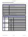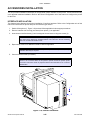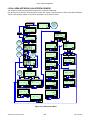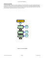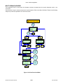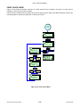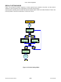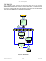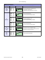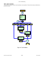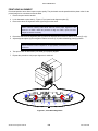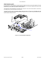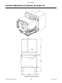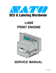
1
S8408/S8412/S8424
PRINTERS
OPERATOR MANUAL
PN: 9001160B
SATO America, Inc.
10350A Nations Ford Road
Charlotte, NC 28273
Main Phone: (704) 644.1650
Technical Support Hotline: (704) 644.1660
Technical Support Fax: (704) 644.1661
E-Mail: [email protected]
[email protected]
www.satoamerica.com
WARNING
THE EQUIPMENT REFERENCED IN THIS DOCUMENT COMPLIES WITH THE REQUIREMENTS IN PART 15
OF FCC RULES FOR A CLASS B COMPUTING DEVICE. OPERATION OF THIS EQUIPMENT IN A
RESIDENTIAL AREA MAY CAUSE UNACCEPTABLE INTERFERENCE TO RADIO AND TV RECEPTION.
PN: 9001160B
TABLE OF CONTENTS
INTRODUCTION
About This Manual
General Description
Control Features
1-2
1-3
1-5
TECHNICAL DATA
Physical Characteristics
Power
Enviromental
Processing
Command
Interface Modules
Regulatory Approvals
Print
Media
Ribbon
Sensing
Character Font Capabilities
Barcode Capabilities
2-2
2-2
2-2
2-2
2-2
2-2
2-2
2-3
2-3
2-3
2-4
2-4
2-5
INSTALLATION
Unpacking & Parts Identification
Printer Installation
Printer Loading
Operational Mode Selection
Interface Selection
RS232C High-Speed Serial Interface
IEEE1284 Parallel Interface
Universal Serial BUS (USB) Adapter
Local Area Network (LAN) Ethernet
802.11G Wireless
All Interfaces
Accessories Installation
Interface
Remote Operator Panel
S8400 Series Operator Manual
3-2
3-3
3-5
3-8
3-9
3-10
3-12
3-13
3-14
3-15
3-17
3-25
3-25
3-26
PN: 9001160B
PRINTER CONFIGURATION
Printer Configuration
Configuration Modes
User Mode
Advanced Mode
Parallel Interface Mode
Serial Interface Mode
Local Area Network (LAN) Interface Mode
Universal Serial BUS (USB) Interface Mode
Centronics Interface Mode
Wireless LAN (Local Area Network) Interface Mode
Service Mode
Factory Mode
Work Shift Mode
Hidden Mode
Download Mode
Boot Download Mode
Print Cancel Mode
Default Settings Mode
Test Print Mode
Hex Dump Mode
CF (Compact Flash) Card Mode
Stand Alone Mode
Menu Definition Tables
4-2
4-3
4-3
4-4
4-5
4-6
4-7
4-8
4-9
4-10
4-11
4-12
4-13
4-14
4-15
4-16
4-17
4-18
4-19
4-20
4-21
4-22
4-23
TROUBLESHOOTING
Error Signal Troubleshooting
Warning Signal Troubleshooting
Troubleshooting Table
Interface Troubleshooting
Parallel Interface
RS232 Serial Interface
Universal Serial Bus (USB) Interface
LAN Ethernet Interface
802.11g Interface
Centronics Interface
Test Print Troubleshooting
Hex Dump Mode
Test Label Printing
Sample Test Label
S8400 Series Operator Manual
5-2
5-6
5-7
5-9
5-9
5-9
5-9
5-10
5-10
5-10
5-11
5-11
5-11
5-11
PN: 9001160B
MAINTENANCE
Cleaning Procedures
Replacement Procedures
Print Head
Platen Rollers
Interface Board
Fan Filter
Adjustment Procedures
Label Sensor Positioning
Print Head Pressure
Print Head Alignmnent
Ribbon Guide Alignment
Media Pressure Roller Balance
Ribbon Cassette Belt Tensioning
Print Head Balance
Eye-Mark/Paper-End Sensor Sensitivity
Gap Sensor Sensitivity
Operational Adjustments
Pitch
Offset
Darkness
6-2
6-3
6-3
6-4
6-5
6-6
6-7
6-7
6-8
6-9
6-10
6-11
6-12
6-13
6-14
6-15
6-16
6-16
6-16
6-16
APPENDIX
Ready/Busy timing Charts
X-On/X-Off Timing Charts
Session Connect/Disconnect Diagram
Printer Dimensions (Standard w/Cassette)
Printer Dimensions (Opposite w/Cassette)
Printer Dimensions (Standard Direct Load)
Printer Dimensions (Opposite Direct Load)
Glossary
S8400 Series Operator Manual
7-2
7-3
7-4
7-5
7-8
7-11
7-14
7-17
PN: 9001160B
INTRODUCTION
• About This Manual
• General Description
• Control Features
S8400 Series Operator Manual
1-1
PN: 9001160B
Unit 1: Introduction
ABOUT THIS MANUAL
This manual is laid out consistent with the product discussed and provides all of the information required for
general printer configuration, operation, troubleshooting, and maintenance. For specialized programming, refer to
the Programming Reference document.
Step-by step maintenance instructions are provided with typical problems and solutions. Become familiar with each
unit and section before installing and maintaining the printer.
This manual also incorporates the use of special information boxes. Examples of these boxes and the type of
information provided in each, are below.
WARNING: PROVIDES INFORMATION THAT, IF UNHEEDED, MAY RESULT IN
PERSONAL INJURY.
CAUTION: PROVIDES INFORMATION THAT, IF UNHEEDED, MAY RESULT IN
EQUIPMENT DAMAGE.
ATTENTION: Provides information that is deemed of special importance but will not
result in personal injury or product damage if unheeded.
NOTE: Provides helpful hints to assist in performing the tasks at hand.
LCD DISPLAY: Provides the specific display that should be visible on the LCD at that
point.
A comprehensive Table Of Contents provided at the front of this manual facilitates rapid movement within. The
contents identify the different Units, Chapters, and some Sections. Each references the page number of their
commencement.
The pages of this manual have embedded headers and footers to assist the user in identifying his or her exact
position within the manual. The header provides the unit number followed by its name. The footer identifies the
product on the left, the page number in the center, and the manual’s part number to the right side of the page.
Page enumeration is two-part with each separated by a hyphen. The first character set references the Unit and the
second identifies the page number within that unit. Page numbers begin with the numeral one (1) at the beginning
of a new unit and ascend sequentially.
ATTENTION: The illustrations and graphics provided in this manual may display
components, assemblies, and purchase options that may not be present on idividual
printers. However, where those instances arise, they are not revalent to the topic
discussed.
S8400 Series Operator Manual
1-2
PN: 9001160B
Unit 1: Introduction
GENERAL DESCRIPTION
The S8400 series print engines are specifically designed for use in high-volume, automated print/apply labeling
applications demanding unparalleled reliability and around the clock operation. These print engines offer four-inch
wide printing ability and are available in 203, 305, and 609 dpi print resolution. However, more compelling is their
user-friendly design and application flexability.
These OEM print engines follow the design concepts and principles of SATO’s previous, market leading, industrial
print engines. The S8400 series can physically and electronically replace any of SATO’s previous S-type OEM
print engines. Additionally, this printer utilizes the same SATO Barcode Printing Language (SBPL) as drives all
current SATO OEM print engines.
The S8400 series print engine is available with many options, including quick-change ribbon cassette, ribbon
saver, and RFID capability.
Center Frame
Power Switch
Operator Panel
Label Sensor Assy
Ribbon Spindle x2
Chassis
Platen Roller x3
Ribbon Cassette
Figure 1-1a, Primary Components
S8400 Series Operator Manual
1-3
PN: 9001160B
Unit 1: Introduction
Front Housing Cover
Rear Housing Covers
Ribbon Supply Spindle
Ribbon Rewind Spindle
Media Guide
Ribbon Roller x2
Printer Chassis
Ribbon Guide
Head Pressure Knob
Label Sensor Adjustment Knob
Head Balance
Print Head Latch
Figure 1-1b, Primary Components
S8400 Series Operator Manual
1-4
PN: 9001160B
Unit 1: Introduction
CONTROL FEATURES
This chapter identifies the interactive control features of the printer. These functions are defined generally here.
More specific explanations will be found throughout this manual on how to use them.
OPERATOR PANEL FEATURES
LED
DEFINITION
POWER
Illuminates green when the printer is powered on. Terminates when powered off.
ONLINE
Illuminates green when the printer is in an online state. Terminates when the printer goes offline.
LABEL
Off = Normal state.
Red Constant = When a Label Error has occurred.
RIBBON
Off = Normal state.
Red Flashing = Ribbon supply is low.
Red Constant = When a Ribbon Error has occurred.
KEYS
DEFINITION
POWER
Removes power supply at its entry to the printer.
LINE
Moves the printer from an online to offline state and vise-versa. Has other special functions as
identified in flow charts throughout this manual as applicable.
FEED
Advances the label media when pressed. Has other special functions as identified in flow charts
throughout this manual as applicable.
FUNCTION
Pressing steps the LCD back to a previous menu. Has other special functions as identified in flow
charts throughout this manual as applicable.
ENTER
Used to select a menu option and to advance the menu screen accordingly. Has other special
functions as identified in flow charts throughout this manual as applicable.
CANCEL
Pressing steps the LCD back to a previous menu. Has other special functions as identified in flow
charts throughout this manual as applicable.
ARROWS
Allows the operator to scroll through various menus and menu options. Has other special
functions as identified in flow charts throughout this manual as applicable.
POTENTIOMETERS
DEFINITION
VOLUME
Allows volume control of the printer’s audible alarm.
PITCH
For adjusting the print position.
OFFSET
Adjusts the peel or dispense stop position.
DARKNESS
Adjusts the print density resulting in a lighter or darker print image.
FUNCTION
LINE
ENTER
LCD DISPLAY
FEED
CANCEL
Figure 1-2, Operator Panel
S8400 Series Operator Manual
1-5
PN: 9001160B
TECHNICAL DATA
•
•
•
•
•
•
•
•
•
•
•
•
•
S8400 Series Operator Manual
Physical Characteristics
Power
Environmental
Processing
Command
Interface Modules
Regulatory Approvals
Print
Media
Ribbon
Sensing
Character Font Capabilities
Barcode Capabilities
2-1
PN: 9001160B
Unit 2: Technical Data
PHYSICAL CHARACTERISTICS
Typical Width
9.65 Inches (245mm)
Typical Height
11.81 Inches (300mm)
Maximum Depth
18.82 Inches (478mm)
Standard Weight
35.27 Pounds (16.0Kg)
POWER
Input Voltage
Power Consumption
Accelleration Perfomance
100-240 Volts AC +/- 10%, 50/60 Hertz +/-5%
220 Watts, 2.7 to 1.1 Amperes (operating)
3.5G (Frequency: 10Hz or below, Vibration Time: within 5 minutes)
ENVIRONMENTAL
Operating Temperature
41 to 104°F (5° to 40°C)
Storage Temperature
0 to 140°F (-20° to 60°C)
Storage Humidity
15 to 85% RH Non-Condensing
Operating Humidity
15 to 85% RH Non-Condensing
PROCESSING
CPU
32 Bit RISC
FLash ROM
4 Megabytes
SDRAM
16 Megabytes
FRAM
32 Kilobytes
Receive Buffer
2.95 Megabytes
SRAM (integrated calendar)
8 Kilobytes
COMMAND
Standard
SATO Barcode Printer Language (SBPL)
INTERFACE MODULES
Enhanced Parallel Port
Serial Port
IEEE1284 (ECP Compatible)
RS232C (9600 to 57,600 bps) - 25 Pin
RS422/485 (9600 to 57600 bps)
RS232C - 9 Pin PCI
Universal Serial Bus (USB)
USB Adapter (12 Mbps) - PCI
Local Area Network (LAN)
10BASE-T/100BASE-TX Automatic Switching
Wireless LAN
802.11g Wireless
REGULATORY
Safety
Radiant Noise
MET, NEMKO-GS, C-MET
FCC (Class B), EN 55022 (Class B)
Efficiency
International Energy Star
Packaging Drop Test
S8400 Series Operator Manual
ISTA-2A
2-2
PN: 9001160B
Unit 2: Technical Data
PRINT
Method
Direct Thermal / Thermal Transfer
Head Width
Maximum Speed
4.09 Inches (104mm)
203 Dots Per Inch (8dpmm): 4 to 16 Inches Per Second (102-406mm/s)
305 Dots Per Inch (12dpmm): 4 to 14 Inches Per Second (102-356mm/s)
609 Dots Per Inch (24dpmm): 2 to 6 Inches Per Second (51-152mm/s)
203 Dots Per Inch (8dpmm)
305 Dots Per Inch (12dpmm)
609 Dots Per Inch (24dpmm)
Resolution
Maximum Printable Area
203 Dots Per Inch (8dpmm): 4.09 x 98.4 Inches Wide (104mm W x 2500mm L)
305 Dots Pre Inch (12dpmm): 4.09 x 59.0 Inches Wide (104mm W x 1500mm L)
609 Dots Per Inch (24dpmm): 4.09 x 15.7 Inches Wide (104mm W x 400mm L)
MEDIA
Width
Media Width: 0.394 to 5.039 Inches (10-128 mm)
Media Width with Backing Paper: 0.5 to 5.1 Inches (13-131 mm)
Length (Pitch)
Type
Media Length: 0.6 Inches (15 mm) (to printable area)
Die-Cut Labels, Waste removed, Roll, 0.125 inch Gap or Eye-Mark
Thickness
Media Handling
0.002 to 0.012 Inches (0.05 - 0.31mm)
Media Width (mm)
Label Supply Load (grams)
Liner Rewind Load (grams)
13 to 18
< 250
< 150
18 to 28
< 400
< 300
28 to 48
< 900
< 300
48 to 63
< 1,200
< 400
63 to 83
< 1,200
< 650
83 +
< 1,400
< 800
RIBBON
Width
Minimum: 0.98 Inches (25mm)
Maximum: 5.04 Inches (128mm)
Length
3280 Feet (1000m)
Ribbon Handling
Ribbon Length (m)
Ribbon Width (mm)
Label Pitch (mm)
1,000
76
60 +
600
39.5 to 75
25 +
450
< 39.5
< 25
Wound
Face In / Face Out
Roll Diameter
Core Diameter
Color
S8400 Series Operator Manual
4.252 Inches (108mm)
1.01 +/-0.008 Inches (25.6mm +/-0.2mm)
Black (standard), Other Tints (non-standard)
2-3
PN: 9001160B
Unit 2: Technical Data
SENSING
Gap
Adjustable
Reflective Eye-Mark
Adjustable
Ribbon Near End
Enable/Disable
Media Out
Constant
Cover-Open
Constant
Head-Open
Constant
CHARACTER FONT CAPABILITIES
MATRIX FONTS
XU
5 dots W x 9 dots H (Helvetica)
XS
17 dots W x 17 dots H (Univers Condensed Bold)
XM
24 dots W x 24 dots H (Univers Condensed Bold)
OA Font (OCR-A)
203dpi (8dots/mm): 15 dots W x 22 dots H
305dpi (12dots/mm): 22 dots W x 33 dots H
609dpi (24dots/mm): 44 dots W x 66 dots H
OB Font (OCR-B)
203dpi (8dots/mm): 20 dots W x 24 dots H
305dpi (12dots/mm): 30 dots W x 36 dots H
609dpi (24dots/mm): 60 dots W x 72 dots H
AUTO SMOOTHING FONTS
XB
48 dots W x 48 dots H (Univers Condensed Bold)
XL
48 dots W x 48 dots H (Sans Serif)
VECTOR FONT
Proportional or Fixed Spacing
Font Size 50 x 50 dots to 999 x 999 dots
Helvetica, 10 Font Variations
AGFA RASTER FONTS
A Font
CG Times, 2 to 99 pt. (4-999 dots)
B Font
CG Triumvirate, 2 to 99 pt. (4-999 dots)
DOWNLOADABLE FONTS
Compact Flash Card required
CHARACTER CONTROL
Expansion up to 12 x in either the X or Y coordinates.
Character Pitch Control
Line Space Control
Journal Print Facility
0, 90, 180, and 270 Degree Rotation
S8400 Series Operator Manual
2-4
PN: 9001160B
Unit 2: Technical Data
BAR CODE CAPABILTIES
Linear Bar Codes
UPC A/E
EAN 8/13
Code 39
Code 93
Code 128
Interleaved 2 of 5
Industrial 2 of 5
Matrix 2 of 5
Bookland
RSS-14
MSI
POSTNET
UCC/EAN 128
NW-7 (Codabar)
Two Dimemsional
QR Code
Data Matrix (ECC200)
Maxi Code
PDF417
Composite Symbology
Bar Width Ratio
Bar Height
1:2, 1:3, 2:5, User definable bar widths
4 to 999 dots, User progammable
Rotation
Sequential Numbering
Graphics
Form Overlay
S8400 Series Operator Manual
0, 90, 180, and 270 Degrees
Sequential numbering of both numerics and bar codes
Full dot addressable graphics, SATO Hex/Binary, BMP or PCX formats
Form overlay for high-speed editing of complex formats
2-5
PN: 9001160B
INSTALLATION
•
•
•
•
•
•
S8400 Series Operator Manual
Unpacking & Parts Identification
Printer Installation
Printer Loading
Operational Mode Selection
Interface Selection
Accessories Installation
3-1
PN: 9001160B
Unit 3: Installation
UNPACKING & PARTS IDENTIFICATION
Unpack the printer as directed in the folowing procedure.
1.
Place the shipping container (box) upright on a stable, flat surface.
2.
Open the box, remove any loose items and the first layer of packing material.
3.
Carefully lift the printer and accessories from the box and place them on a stable, flat surface.
4.
Remove the plastic covers from the packed items and visually inspect for physical damage.
5.
Ensure all components are present as dictated on the Packing List.
6.
Report damaged property to the shipping carrier.
Figure 3-1, Unpacking
S8400 Series Operator Manual
3-2
PN: 9001160B
Unit 3: Installation
PRINTER INSTALLATION
This chapter provides guidance on how to station, connect, and load the printer once unpacked. Following printer
setup, proceded to the next chapter for information on interface selection.
SITE LOCATION
•
Stationed away from hazardous materials.
•
Stationed within an enclosed structure that conforms to the printer’s enviromental requirements.
•
Stationed within operational distance of the host based on interface specifications.
•
Stationed to allow unimpeded access to the printer for operation, loading, and maintenance.
INSTALLATION REQUIREMENTS
The printer has five bores in its center frame for the purpose of mounting to a support structure. Refer to the
following list of mounting requirements.
•
The support structure must be firmly secured to the floor or production machinery.
•
The support structure must be sturdy and stable so as to prevent unnecessary movement or vibration.
•
The printer is to be mounted to the support structure using attaching hardware design to accommodate the
printer’s weight, as well as, the prevailing operational and enviromental conditions within the facility.
•
A power supply recepticle or junction box is to be properly secured within regulated proximity to the printer.
•
The power supply is to be metered condusive to the printer’s design requirements.
•
The printer must be installed so that its output side is within the designated distance and height relative to the
applicator.
•
Media supply dispensers must be mounted or placed with operational distance of the printer’s input side.
NOTE: Figures 3-2 and 3-3 are to be used as instructional displays only and are not to
be literally interpretted as precise examples.
Printer
Applicator
Packaging
Production Line
Figure 3-2, Typical Printer/Applicator Process
S8400 Series Operator Manual
3-3
PN: 9001160B
Unit 3: Installation
Figure 3-3, Printer Mounting
Host Computer
Breaker Box
Applicator
Printer
Interface Card
Interface Cable
Power Cord
EXT Interface
OR
Figure 3-4, Printer Connection
ATTENTION: Figure 3-4 displays the printer interfaced with a host computer.
However, the printer may also be interfaced with a PLC, keyboard, scanner, etc.
S8400 Series Operator Manual
3-4
PN: 9001160B
Unit 3: Installation
PRINTER LOADING
WARNING: AVOID PHYSICAL CONTACT WITH THE PRINT HEAD TO PREVENT
BURNED FINGERS/HANDS AND COMPONENT DAMAGE.
MEDIA SELECTION
The size and type of labels to be printed should have been taken into consideration before printer purchase.
Ideally, the media width will be equal to, or just narrower than, the print head. Using media that does not cover the
print head will allow the platen roller to tread upon its surface resulting in premature wear. The media edge will also
wear a groove in the platen roller affecting print quality.
There are two types of media that may be used: thermal transfer and direct thermal. Thermal transfer media
requires the use of ribbon stock for print application. In such a scenario, it is the ribbon stock (carbon paper) that
contains the ink that will be transfered to the media.
Direct thermal media has thermally reactive material embedded within and is brought to the surface through heat
penetration by print head contact. Only load ribbon stock into the printer if that media type is to be used.
MEDIA LOADING
To load label media, unlatch the print head and remove any remnants that may exist of the prior media supply.
Feed the free end of the media from the printer’s left side, beneath the shaft of the media guide, between the upper
and lower halves of the label sensor, across the top of all forthcoming rollers, and through to protrude six or more
inches beyond the printer chassis.
Ensure the media is flush against the printer’s back side (toward the center wall) and then adjust the media guide
inward until it almost makes contact with the media’s backing paper.
Remove all labels from the backing paper that extend beyond the printer chassis and relatch the print head.
Lift upward on the pressure roller release knob (purple) and allow the pressure roller plate to fall to a vertical
position. Route the backing paper’s free end around the front of the printer chassis, beneath the front platen roller
and onward between the second platen roller and the pressure roller. Pull the free end of the backing paper to
remove all slack while lifting the pressure plate until latched. Refer to Figures 3-5 and 3-6 for visual assistance.
NOTE: Properly installed label media will be oriented so that the label side is upward
and the backing paper is downward resting upon the printer chassis.
NOTE: Refer to the Printer Configuration unit of this manual for media configuration
instructions and the Adjustment chapter of the Maintenance unit for label sensor
adjustment instructions as necessary.
RIBBON LOADING
To load ribbon stock, unlatch the print head and remove exhausted ribbon stock if applicable. Insert an unused
ribbon roll, with ribbon core, fully onto the ribbon supply boss (left) and an empty core onto the ribbon rewind boss
(right). Route the ribbon’s free end around the print assembly and tape it to the blank core on the rewind boss.
Rotate the core a couple of times while holding the boss stationary to take up take up slack. Refer to Figure 3-5 and
Figure 3-6 for visual assistance.
NOTE: Properly installed ribbon stock will be oriented so that its dull, ink side is facing
the printer chassis while the ribbon is dispensed and taken up on the right side of
each roll. The non-ink side of the riibon stock is the shiniest of the two surfaces.
S8400 Series Operator Manual
3-5
PN: 9001160B
Unit 3: Installation
Power Switch
Ribbon Stock (wound face in)
Ribbon Core
Ribbon Boss
Print Assembly
Ribbon Stock (wound face out)
Label Sensor
Media Guide
Printer Chassis
Platen Rollers
Pressure Roller Release
Pressure Roller
Paper Backing
Label Media
Figure 3-5, Ribbon & Media Loading
Figure 3-6a, Ribbon Cassette Loading
S8400 Series Operator Manual
3-6
PN: 9001160B
Unit 3: Installation
Figure 3-6b, Ribbon Cassette Loading
Figure 3-6c, Ribbon Cassette Loading
S8400 Series Operator Manual
3-7
PN: 9001160B
Unit 3: Installation
OPERATIONAL MODE SELECTION
There are two modes of printer operation: Dispense or Continuous. The difference between the two is the way that
the label and paper backing is ejected. Before printer configuration, one must determine which mode will be used.
This chapter identifies and defines the functional differences between the two.
DISPENSE MODE
With this method of operation, after printing, the printer feeds the first (outermost) label so that it is fully extended
out of the printer’s front for dispensing. Printing of the next label will not begin until the prior printed label has been
removed. This mode of operation is specifically suited for the use of automated machinery to remove the printed
and dispensed label to apply to packaging, etc.
Upon removal of the prior printed label, the printer repositions the media so that the next label in line may be
printed, then prints. The before-mentioned cycle, repeats for each consecutive label.
Printer configuration for the backfeed function may be found in the Advanced Mode of the Configuration unit of this
manual. Refer to the Table of Contents for the page number.
CONTINUOUS MODE
With this method of operation, the media remains in position for printing at all times. To do so, means that the
previous printed label is never in proper position for dispensing and thusly, must be manually removed form the
printer rather than through the application of automated machinery.
Printer configuration for Continuous mode of operation may be found in the Advanced Mode of the Configuration
unit of this manual. Refer to the Table of Contents for the page number.
ATTENTION: Refer to the Printer Configuration unit of this manual to program the
printer’s internal memory to suit individual needs using the printer’s integrated menu
options. Refer to the Programming Reference document to remotely program the
printer’s features and functions through a host system.
S8400 Series Operator Manual
3-8
PN: 9001160B
Unit 3: Installation
INTERFACE SELECTION
This unit presents the printer interface types and their specifications. These specifications include detailed
information to assist in the selection of the most appropriate method for the printer to interface with the host. The
five acceptable interface methods are:
•
•
•
•
•
RS232C High-Speed Serial
IEEE1284 Parallel
Universal Serial Bus (USB)
Local Area network (LAN) Ethernet
802.11g Wireless
Following the selection of the desired interface, proceed to the next unit for instructions on how to configure the
printer for that interface type.
WARNING: NEVER CONNECT OR DISCONNECT INTERFACE CABLES (OR USE
A SWITCH BOX) WITH POWER APPLIED TO EITHER THE HOST OR THE
PRINTER. THIS MAY CAUSE DAMAGE TO THE INTERFACE CIRCUITRY IN THE
PRINTER/HOST AND IS NOT COVERED BY WARRANTY.
NOTE: Some hosts monitor the Request-To-Send (RTS) signal (pin 4 of 25) to
determine if the printer is ready to receive data. Since the printer does not generate
this signal, the RTS line must be held true (high) in order to allow communication. This
can be performed by connecting the RTS pin to the Clear-To-Send (CTS) signal (pin 5
of 25).
Interface Card
Screw x2
Figure 3-7, Interface Installation
S8400 Series Operator Manual
3-9
PN: 9001160B
Unit 3: Installation
RS232C HIGH-SPEED SERIAL INTERFACE
This High Speed Serial Interface is a Plug-In Interface Module that can be installed in the printer by the user.
INTERFACE SPECIFICATIONS
Asynchronous ASCII
Half-duplex communication
Bi-Directional Communication
Data Transmission Rate
9600, 19200, 38400, 57600 bps
Transmission Form
Start, b1, b2, b3, b4, b5, b6, b7, b8, Stop (b8 will be omitted if using 7 bit oriented)
Data Length
7 or 8 bit (selectable)
Stop Bit
1 or 2 bit (selectable)
Parity Bit
ODD, EVEN, NONE (selectable)
Codes Used
ASC II Character Codes: 7 bits, Graphics: 8 bits
Control Codes
STX (02H), ETX (03H), ACK (06H), NAK (15H)
Connector (Printer Side)
DB-25S Male (equivalent), 9-pin Serial Interface (PCI)
Cable Connector
DB-25P Female (equivalent), 9-pin Serial Interface (PCI)
Cable Length
5 meters or less.
Signal Levels
High = +5V to +12V, Low = -5V to -12V
Protocol
Ready/Busy, X-On/X-Off, Protocol for Driver, Status4, Status5
DIPSWITCH SETTINGS
SWITCH
COMPONENT
1
Data Bit
SETTINGS
ON
7 Bits
OFF
8 Bits
2
2&3
4
5&6
7&8
Parity
ON
ON
Reserved
ON
OFF
ODD
OFF
ON
EVEN
OFF
OFF
NONE
Stop Bit
Baud Rate
Protocol
S8400 Series Operator Manual
3
ON
2 Bits
OFF
1 Bit
5
6
ON
ON
57600 bps
ON
OFF
38400 bps
OFF
ON
19200 bps
OFF
OFF
9600 bps
7
8
ON
ON
Reserved: Status2 & 3 (when compatible mode is OFF)
ON
OFF
Protocol for Driver, Status5
OFF
ON
X-ON/X-OFF
OFF
OFF
Ready/Busy
3-10
PN: 9001160B
Unit 3: Installation
READY/BUSY INTERFACE SIGNALS
PIN
DIRECTION
SIGNAL DEFINITION
1
Reference
FG (Frame Ground)
2
To Host
TD (Transmit Data) - Data from the printer to the host computer. Sends X-On/X-Off characters
or status data (bi-directional protocols).
3
To Printer
RD (Receive Data) - Data to the printer from the host computer.
4
To Host
RTS (Request to Send) - Used with Ready/Busy flow control to indicate an error condition.
RTS is high and remains high unless the print head is open (in this case, RTS would return to
the high state after the print head is closed and the printer is placed back on-line) or an error
condition occurs during printing (e.g., ribbon out, label out).
5
To Printer
CTS (Clear to Send) - When this line is high, the printer assumes that data is ready to be
transmitted. The printer will not receive data when this line is low. If this line is not being used,
it should be tied high (to pin 4).
6
To Printer
DSR (Data Set Ready) - When this line is high, the printer will be ready to receive data. This
line must be high before data is transmitted. If this line is not being used, it should be tied high
(to pin 20).
7
Reference
SG (Signal Ground)
20
To Host
DTR (Data Terminally Ready) - This signal applies to Ready/Busy flow control. The printer is
ready to receive data when this pin is high. It goes low when the printer is off-line, either
manually or due to an error condition, and while printing in the single job buffer mode. It will
also go low when the data in the buffer reaches the buffer near full level.
READY/BUSY CABLE REQUIREMENTS
DB9
DB25
HOST
DIRECTION
DB25
PRINTER
1
1
FG (Frame Ground)
Bi-Directional
1
FG (Frame Ground)
2
3
RD (Receive Data)
To Host
2
TD (Transmit Data)
3
2
TD (Transmit Data)
To Printer
3
RD (Receive Data)
8
5
CTS (Clear To Send)
To Printer DB9-6
4
RTS (Request To Send)
4
20
DTR (Data Terminal Ready)
To Printer DB9-4
5
DSR (Data Set Ready)
6
6
DSR* (Data Set Ready)
To Host
6
DTR (Data Terminal Ready)
5
7
SG (Signal Ground)
Bi-Directional
7
SG (Signal Ground)
* This connection at the host side of the interface would depend upon the pin that is being used as the Ready/Busy signal by
the driving software. Typically, on a PC, it would be either CTS (pin5) or DSR (pin 6) on a DB-25 connector.
Figure 3-8, Serial Connector Pin Assignments
S8400 Series Operator Manual
3-11
PN: 9001160B
Unit 3: Installation
X-ON/X-OFF CABLE REQUIREMENTS
Communicates with the host to determine if the printer is ready to receive data by sending “XON” (HEX 11H) or “XOFF” (HEX
13H) code to the TD line. The single and multiple item buffers are switchable in the Interface Mode of the printer.
DB9
DB25
HOST
DIRECTION
DB25
PRINTER
1
1
FG (Frame Ground)
Bi-Directional
1
FG (Frame Ground)
2
3
RD (Receive Data)
To Host
2
TD (Transmit Data)
3
2
TD (Transmit Data)
To Printer
3
RD (Receive Data)
5
7
SG (Signal Ground)
Bi-Directional
7
SG (Signal Ground)
NOTE: Depending on the host used, it may be required to loop CS and RS
(maintaining at high-level) on the host side. For more information, refer to the host
computer documentation.
NOTE: Refer to the Charts & Diagrams unit of this manual to view timing charts for
Ready/Busy and X-ON/X-OFF.
IEEE1284 PARALLEL INTERFACE
The parallel interface is a plug-in module that can be installed by the user and conforms to IEEE1284
specifications. It automatically detects the IEEE1284 signals and operates in the high speed mode. If the
IEEE1284 signals are not detected, it will operate in the slower standard Centronics mode. For this reason, an
interface cable and host interface conforming to the IEEE1284 specification must be present to fully utilize the
speed capabilities. This interface also operates bi-directionally and can report the status of the printer back to the
host.
SPECIFICATIONS
Printer Connector
AMP 57-40360 DDK (or equivalent)
Cable Connector
AMP 57-30360 DDK (or equivalent)
Cable
1.5 meter or less
Signal Level
High = +2.4V to +5.0V, Low = 0V to -0.4V
Data Stream
<ESC>A . . Job#1 . . <ESC>Z<ESC>A . . Job#n . . <ESC>Z
Figure 3-9, Parallel Connector Pin Assignments
S8400 Series Operator Manual
3-12
PN: 9001160B
Unit 3: Installation
PIN ASSIGNMENTS
PIN
SIGNAL
DIRECTION
PIN
SIGNAL
DIRECTION
1
Strobe
To Printer
19
Strobe Return
Reference
2
Data 1
To Printer
20
Data 1 Return
Reference
3
Data 2
To Printer
21
Data 2 Return
Reference
4
Data 3
To Printer
22
Data 3 Return
Reference
5
Data 4
To Printer
23
Data 4 Return
Reference
6
Data 5
To Printer
24
Data 5 Return
Reference
7
Data 6
To Printer
25
Data 6 Return
Reference
8
Data 7
To Printer
26
Data 7 Return
Reference
9
Data 8
To Printer
27
Data 8 Return
Reference
10
ACK
To Host
28
ACK Return
Reference
11
Busy
To Host
29
Busy Return
Reference
12
Ptr Error
To Host
30
PE Return
Reference
13
Select
To Host
31
INIT
From Host
14
AutoFD1
To Host
32
Fault
To Host
15
Not Used
33
Not Used
16
Logic Gnd
34
Not Used
17
FG
Frame Gnd
35
Not Used
18
+5V (z=24k ohm)
To Host
36
SelectIn1
From Host
1 Signals required for ieee 1284 mode.
UNIVERSAL SERIAL BUS (USB)
The Universal Serial Bus (USB) interface is a Plug-In Interface Module that can be installed by the user. It requires
a driver (shipped with each printer that has the interface installed) that must be loaded onto the PC and configured
to support USB peripherals using Windows 2000 or above. Details for loading the USB driver are contained in the
USB Interface Manual that is shipped with each printer with a USB Optional interface installed. Up to 127 devices
may be connected to a USB port using powered hubs.
ATTENTION: This Interface Type Is Not Compatible With Windows 98 Or Windows
Me.
SPECIFICATIONS
Printer Connector
USB Type B Plug
Cable
10 feet (3 m) maximum
Host
Windows 2000 or above with USB Port
Power Supply
BUS Power through cable
Power Consumption
+5 V at 80 ma
S8400 Series Operator Manual
3-13
PN: 9001160B
Unit 3: Installation
LOCAL AREA NETWORK (LAN) ETHERNET
A Local Area Network (LAN) interface is an optional Plug-In Interface Module that can be installed by the user. It
requires a driver shipped with each printer that has the interface installed. The driver that must be loaded onto the
host computer and configured to run one of the supported network protocols using a 10Base-T or 100Base-TX
LAN connection. Details for loading the LAN driver are contained in the LAN Interface Manual that is shipped with
each printer with a LAN Optional interface installed.
SPECIFICATIONS
Connector
RJ-45 Receptacle
Cable
10/100BaseT Category 5
Cable Length
100 meters or less
Power Supply
Powered from printer
Protocol
Status3 return
Protocol for Driver (cyclic response mode)
Protocol for Driver (ENQ response mode)
Status5 return
IP Address
0.0.0.0 to 255.255.255.255
Subnet Mask
0.0.0.0 to 255.255.255.255
Gateway Address
0.0.0.0 to 255.255.255.255
DIPSWITCH SETTINGS
SWITCH
SETTING
1
Reserved (setup prohibited).
2
LAN board EEPROM initialization (configuration).
3
Print configuration details on a label.
4
Print a self-diagmosis of the board onto a label.
SOFTWARE SPECIFICATIONS
Corresponding Protocol
TCP/IP
Network Layer
ARP, RARP, IP, ICMP
Session Layer
TCP, UDP
Application Layer
LPD, FTP, TELNET, BOOTP, DHCP
NOTE: Print data can be sent by LPR and FTP of TCP/IP and dedicated socket protocol. Printer status is obtainable by
dedicated socket protocol.
NOTE: In the TCP/IP protocol enviroment, LPD and FTP are provided for printing; TELNET for variable setup; ARP, RARP,
and BOOTP/DHCP for address setup.
LPD protocol complies with RFC1179 and handles the list of logical printer name as queue name such as lp, sjis, euc. In
addition, a banner page can be printed by a proper setup.
When sending the job by LPR, the transmission order of data file/control file within the job will not affect print operation. In
addition, if the banner page is specified, it will be added to each data file. Job deletion by LPR is not available.
FTP protocol complies with RFC959 and handles the list of logical printer name as a transfer directory. File transfer to this
directory executes print operation. It is possible to specify ASCII(A), Binary(I) and TENEX(L8) as transfer mode - although the
mode difference is dependent on the client. A banner page may be printed with a proper setup.
TELNET Complies with RFC854. This operation consists of interactive menu form and enables change and reference of
internal setup, and to display status. To change the setup, enter “root” user and password at the time of login. Default of root
pasword is set as null (linefeed only).
S8400 Series Operator Manual
3-14
PN: 9001160B
Unit 3: Installation
802.11G WIRELESS
The wireless print server provides easy printer interface with 802.11g Wi-Fi compliant networks free of wired
connections. Each printer is shipped with an integrated driver and interface installed. The driver must be loaded
onto the host computer and configured to run one of the supported protocols.
SPECIFICATIONS
Variable Data Rates
54, 11, 5.5, 2 and 1 Mbps
Frequency Band
2.4 GHz ISM Band
Wired Equivalent Privacy
128 bit, 64 bit (compatible with 40bit), none (WPA)
Sensitivity
(typ, AAWGN, 8E-2 PER): -91dBm at 1Mbps, -88dBm at 2 Mdps, -87dBm at 5.5Mbps, 84dBm at 11Mbps.
Range
100m indoors, 300m outdoors (enviromentally dependent)
Protocols
TCP/IP, IPX/SPX, Direct Mode IPX/IP, DLC/LLC, NetBEUI, NetBIOS/IP
Protocol
Status3 return
Protocol for Driver (cyclic response mode)
Protocol for Driver (ENQ response mode)
Status5 return
IP Address
0.0.0.0 to 255.255.255.255
Subnet Mask
0.0.0.0 to 255.255.255.255
Gateway Address
0.0.0.0 to 255.255.255.255
Communication Mode
802.11 Ad hoc, Ad hoc, Infrastructure
SSID
Optional alphanumeric character string (up to 32 characters)
Channels
01 to 11
DIPSWITCH SETTINGS
The dipswitches serve to initialize the configuration saved on the Wireless-LAN board, print the configuration, and make a selfdiagnosis. To communicate with the host,set the communication mode by through switches 5 and 6, then set the remaining
switches to the OFF position.
Print of configuration and self-diagnsis are operable only on the screen after turning on the printer. Ensure all switches are in
the OFF position when operating the printer.
SWITCH
1
2
3
4
SETTING
OFF
Normal operating setting.
OFF
Normal operating setting.
ON
Initialization/Reset to factory default upon power up.
OFF
Normal operating setting.
ON
Configuration report upon power up - prints diagnostic report upon powering up.
OFF
ON
Wireless Mode setting.
NOTE: The communication mode may be set within the printer’s Interface Mode. Go to [Communication] of the Interface Mode
to enable setup by either the dipswitches or through the Interface Mode.
WIRELESS LAN SIGNAL STRENGTH
Off
Network Port
S8400 Series Operator Manual
Link LED
0 to 50% (weak)
Blinking
50 to 75% (medium)
On
75 to 100% (strong)
3-15
PN: 9001160B
Unit 3: Installation
LED INDICATOR STATUS
Network Port
Link LED (green)
Front Panel
Network Port
Status LED (orange)
Front Panel
Wireless LED (green)
Front Panel
Off
Blinking
--Waiting for link
On
Linked
Off
---
Blinking
Blinking
On
Receiving packet
Ad-hoc mode
Infrastructure mode
SOFTWARE SPECIFICATIONS
Corresponding Protocol
TCP/IP
Network Layer
ARP, RARP, IP, ICMP
Session Layer
TCP, UDP
Application Layer
LPD, FTP, TELNET, BOOTP, DHCP
NOTE: Print data can be sent by LPR and FTP of TCP/IP and dedicated socket protocol. Printer status is obtainable by
dedicated socket protocol.
NOTE: In the TCP/IP protocol enviroment, LPD and FTP are provided for printing; TELNET for variable setup; ARP, RARP,
and BOOTP/DHCP for address setup.
LPD protocol complies with RFC1179 and handles the list of logical printer name as queue name such as lp, sjis, euc. In
addition, a banner page can be printed by a proper setup.
When sending the job by LPR, the transmission order of data file/control file within the job will not affect print operation. In
addition, if the banner page is specified, it will be added to each data file. Job deletion by LPR is not available.
FTP protocol complies with RFC959 and handles the list of logical printer name as a transfer directory. File transfer to this
directory executes print operation. It is possible to specify ASCII(A), Binary(I) and TENEX(L8) as transfer mode - although the
mode difference is dependent on the client. A banner page may be printed with a proper setup.
TELNET Complies with RFC854. This operation consists of interactive menu form and enables change and reference of
internal setup, and to display status. To change the setup, enter “root” user and password at the time of login. Default of root
pasword is set as null (linefeed only).
Figure 3-10, Socket Connection Diagram
S8400 Series Operator Manual
3-16
PN: 9001160B
Unit 3: Installation
ALL INTERFACES
RECEIVE BUFFER
The data stream is received from the host to the printer one job at a time. This allows the software program to
maintain control of the job print queue so that it can move a high priority job in front of ones of lesser importance.
A multiple job buffer allows the printer to continuously receive print jobs while compiling and printing other jobs at
the same time. It acts much like a Print buffer to maximize the performance of the host and the printer.
The printer receives and prints one job at a time. If a print job exceeds the buffer size, transmission will be rejected
by the printer. Error conditions that occur during the Print Data transmission will cause the printer to return a NAK.
ACK/NAK PROTOCOL
Bi-Directional ACK/NAK protocol is used for error control. In a normal transmission sequence when the
transmission is received, the printer will return an ACK (06H) signifying that it was received without a transmission
error. After the transmission command structure has been analyzed, a status byte is returned to the host. This
status byte informs the host of the validity of the command structure.
If the command structure is error free, the printer proceeds with the print operation. When the print operation is
completed, a Printer Status message is returned to the host. If an error was detected during the initial transmission
sequence, a NAK (15H) will be returned signalling to the host that the received transmission contained errors and
must be resent. If the returned Status byte indicates a command structure error, the error must then be corrected
before the print data is resent to the printer.
A valid transmission to the printer must be bounded by an STX/ETX pair, with the STX (02H) signifying the start of
the Print Data and ending with an ETX (03H) signifying the end.
STATUS5 RETURN
This communication protocol is designed for the purpose of monitoring and controlling print data status in the host
and featuring various functions.
INTERFACE SIGNALS
PIN
DIRECTION
SIGNAL DEFINITION
1
Reference
FG (Frame Ground)
2
To Host
TD (Transmit Data) - Data from the printer to the host computer.
3
To Printer
RD (Receive Data) - Data to the printer from the host computer.
7
Reference
SG (Signal Ground)
CABLE REQUIREMENTS
Depending on the host used, it may need to loop CS and RS (maintaining at high level) on the hose side. For additional
information, refer to the host computer documentation.
DB9
DB25
HOST
DIRECTION
DB25
PRINTER
1
1
FG (Frame Ground)
Bi-Directional
1
FG (Frame Ground)
2
3
RD (Receive Data)
To Host
2
TD (Transmit Data)
3
2
TD (Transmit Data)
To Printer
3
RD (Receive Data)
5
7
SG (Signal Ground)
Bi-Directional
7
SG (Signal Ground)
S8400 Series Operator Manual
3-17
PN: 9001160B
Unit 3: Installation
RECEIVE BUFFER CONTROL
Causes For Receive Buffer Near Full
Receive buffer near full occurs when the remaing free space of the buffer drops to
0.95MB of 2.95MB capacity or when the remaining free space is available for storing
50 of 500 items in the history buffer.
Release Of Receive Buffer Near Full
Receive buffer near full can be released when the remaining free space rises to
1.95MB or when the remaining free space is available for storing 200 items in the
history buffer.
STATUS5 TIMING CHARTS
NORMAL PROCESS
(Figure 3-11a)
CANCEL PROCESS
(Figure 3-11b)
ERROR PROCESS
(Figure 3-11c)
S8400 Series Operator Manual
3-18
PN: 9001160B
Unit 3: Installation
STATUS5 TIMING CHARTS
PRINT PROCESS
(Figure 3-11d)
COMMAND PROCESS
(Figure 3-11e)
BCC ERROR PROCESS
(Figure 3-11f)
S8400 Series Operator Manual
3-19
PN: 9001160B
Unit 3: Installation
EXTERNAL SIGNAL
The external signal interface is designed to connect the printer to an applicator. Proceed to the printer’s Advanced
Mode for various setup activities related to the external signal.
There are two connector types available for the external signal interface, one with a 14-pin connector and the other
with a 25-pin connector.
SPECIFICATIONS
Signal Level
High: +2.4 to +5.0V,
Low: +0.0 to +0.4V
Issuing/Reissuing EXT signal
Enable/Disable in the Advanced Mode.
Switching EXT signal
Switching jumper connector to enable +24V output by 24V and 27V power supplies.
When using 24V power supply: Short IN 24V side by jumper connector
When using 27V power supply: Short IN 27V side by jumper connector.
Signal Types
Type I
Print end signal (PREND) is “low” before printing labels, “high” after
completion of print, and “low” 20 miliseconds later.
Type II
Print end signal (PREND) is “high” before printing labels, “low” after
completion of print, and “high” 20 miliseconds later.
Type III
Print end signal (PREND) is “low” before printing labels, “high” from start to
end of print, and “low” upon completion of print.
Type IV
Print end signal (PREND) is “high” before printing labels, “low” from start to
end of print, and “high” upon completion of print.
14-PIN CONNECTOR ASSIGNMENTS
PIN
SIGNAL NAME
DIRECTION
LEVEL
MAX CURRENT
1
Paper End
Output
Low
5V, 400mA
2
Ground
--
--
--
3
Ribbon End
Output
High
5V, 400mA
4
Machine Error
Output
Low
5V, 400mA
5
Print Start (PRIN)
Input
Low
High: high impedance, Low: -15mAor more, 0V
6
Print End (PREND)
Output
Low
5V, 400mA
7
Reprint (PRIN2)
Input
Low
High: high impedance, Low: -15mAor more, 0V
8
EXT5V_IN
Input
9
Online
Output
Low
5V, 400mA
10
Ribbon Near End
Output
Low
5V, 400mA
11
--
--
--
--
12
+24V
--
--
--
13
+5V
--
--
--
14
FG
--
--
--
5V
Choose from Type I to Type IV for PREND (the output signal for Pin 6).
S8400 Series Operator Manual
3-20
PN: 9001160B
Unit 3: Installation
25-PIN CONNECTOR ASSIGNMENTS
PIN
SIGNAL NAME
DIRECTION
LEVEL
MAX CURRENT
1
Frame Ground
---
---
---
2
+5V
---
---
---
3
---
---
---
---
4
Machine Error
Output
Low
5V, 400mA
5
Print End (PREND)
Output
Low
5V, 400mA
6
Online
Output
Low
5V, 400mA
7
---
---
---
---
8
Reprint (PRIN2)
Input
Low
High: high impedance, Low: -15mA or more, 0V
9
---
---
---
---
10
---
---
---
---
11
EXT_GND
---
---
---
12
+5V
---
---
---
13
+24V
---
---
---
14
GND
---
---
---
15
EXT_GND
---
---
---
16
Ribbon End
Output
High
5V, 400mA
17
Paper End
Output
Low
5V, 400mA
18
Ribbon Near End
Output
High
5V, 400mA
19
---
---
---
20
Print Start (PRIN)
Input
Low
High: high impedance, Low: -15mA or more, 0V
21
---
---
---
---
22
---
---
---
---
23
---
---
---
---
24
EXT5V_IN
Input
---
5V
25
GND
---
---
---
Choose from Type I to Type IV for PREND (the output signal for Pin 5). PREND will not be output when the command is “0” in
the cutter mode.
Connect EXT_GND (Pins 11, 15) to external equipment GND.
Supply EXT5V_IN (Pin 24) 5V from the external power supply.
Figure 3-12, Input/Output Circuit Diagram
S8400 Series Operator Manual
3-21
PN: 9001160B
Unit 3: Installation
Figure 3-13, 14-Pin Connector Assignments
Figure 3-14, 25-Pin Connector Assignments
INPUT SIGNAL WAVE FORM
START PRINTING
(Figure 3-15a)
REPRINTING
(Figure 3-15b)
S8400 Series Operator Manual
3-22
PN: 9001160B
Unit 3: Installation
OUTPUT SIGNAL WAVE FORM
BASIC OPERATION
(Figure 3-16a)
PAPER END
(Figure 3-16b)
RIBBON END
(Figure 3-16c)
MACHINE ERROR
(Figure 3-16d)
S8400 Series Operator Manual
3-23
PN: 9001160B
Unit 3: Installation
Figure 3-17, Operation Mode Flow Chart
S8400 Series Operator Manual
3-24
PN: 9001160B
Unit 3: Installation
ACCESSORIES INSTALLATION
This unit provides installation instructions of the purchase options available for this printer. These instructions only
cover physical hardware installation. Refer to the Printer Configuration unit of this manual to configure the printer
for their use.
INTERFACE INSTALLATION
The diagram below displays the physical installation of interface hardware. Refer to the Configuration unit of this
manual for instructions on printer setup for the interface type chosen.
1.
Switch off the printer (1, Figure 3-18) and and follow applicable lockout-tagout procedures.
2.
Remove interface slot covering (not shown) from printer (1) as applicable.
3.
Insert chosen interface board (2) into its assigned slot and secure using two screws (3).
NOTE: The interface slot identified EXT is assigned for peripheral device connection.
The center slot is asigned for standard interface card connection. And the remaining
slot is for use with PCI interface cards.
4.
Repeat steps 2 and 3 for additional interface cards as applicable.
NOTE: Dependent on individual setup and operational requirements, multiple
interface cards may be required.
5.
Connect interface cable (not shown).
NOTE: The interface cable to be used is dependent upon the type of card and the
device to be connected. Refer to this printer’s operator manual for specific printer
connection instructions. Refer to peripheral device’s documentation for its connector
identification.
1
3
2
Figure 3-18, Interface Installation
S8400 Series Operator Manual
3-25
PN: 9001160B
Unit 3: Installation
REMOTE OPERATOR PANEL
This purchase option allows the operator panel to be detached from the printer and secured in a remote location
convenient for user access. Refer to the instructions provided with the kit for installation guidance.
S8400 Series Operator Manual
3-26
PN: 9001160B
PRINTER
CONFIGURATION
• Printer Configuration
• Configuration Modes
• Menu Definition Tables
S8400 Series Operator Manual
4-1
PN: 9001160B
Unit 4: Printer Configuration
PRINTER CONFIGURATION
This unit provides in-depth instruction on printer configuration for operation and for some troubleshooting.
The printer may be configured via the buttons and/or potentiometers located on the printer’s operator panel. All of
the printer’s buttons, switches, and potentiometers are used singularly, or in conjunction, to perform configuration
activities.
Refer to the Control Features chapter of the Introduction unit for identification of specific interface features.
S8400 Series Operator Manual
4-2
PN: 9001160B
Unit 4: Printer Configuration
CONFIGURATION MODES
This chapter provides an overview of the various configuration modes of the operation menu. All of the
configuration activities are performed via the use of the operator panel located on the printer’s face. However,
many settings may also be controlled via external software commands. In the case of conflict between external
software commands and internal software commands (control panel settings) the printer will always use the last
valid setting, unless a priority function is provided via the LCD menu.
USER MODE
This mode allows configuration of printing features that are prone to change from job to job. These are some of the
most basic and common adjustments of all of the configuration modes.
Use the keys of the printer’s operator panel to select and enter the required options. Refer to the Menu Definition
Tables in the following chapter to provide an explanation of each menu screen.
POWER
Displayed
if password
feature is
enabled
PASSWORD
0000
ONLINE
QTY: 000000
LINE
PRINT DARKNESS
1
2
3
4
5
OFFLINE
QTY: 000000
LINE
Cancels
print job
CANCEL
ENTER
ENTER
CANCEL
PITCH OFFSET
ONLINE MODE
+XX MM
CANCEL
SEMBL
Mode
CANCEL
ENTER
ENTER
CF Card
Mode
USER MODE
Interface
Mode
CANCEL
ENTER
Advanced
Mode
OFFSET VOLUME
PITCH
+X.XX
OFFSET
-X.XX
DARKNESS
XX
CANCEL
ENTER
PRINT SPEED
XX IPS
CANCEL
ENTER
Figure 4-1, User Mode
S8400 Series Operator Manual
4-3
PN: 9001160B
Unit 4: Printer Configuration
ADVANCED MODE
The Advanced Mode is provided to make advanced printer operational adjustments. Typically, once these
adjustments or settings have been made, they will not require additional address unless the application changes
significantly.
Use the keys of the printer’s operator panel to select and enter the required options. Refer to the Menu Definition
Tables in the following chapter to provide an explanation of each menu screen.
POWER
ZERO SLASH
Displayed
if password
feature is
enabled
PASSWORD
0000
YES
NO
ENTER
ONLINE
PRINT METHOD
QTY: 000000
AUTO ONLINE
LINE
TRANSFER
DIRECT
YES
NO
ENTER
ENTER
OFFLINE
QTY: 000000
SENSOR TYPE
Cancels
print job
ENTER
PRINT OFFSET
GAP
TOP I-MARK
BOTTOM I-MARK
CANCEL
V: +XXXX
H: +XXXX
ONLINE MODE
ENTER
ENTER
SEMBL
Mode
HEAD CHECK
ENTER
ENABLE
SET CALENDAR
DISABLE
YES
CF Card
Mode
Enable
ENTER
USER MODE
Interface
Mode
Disable
ENTER
Yes
ENTER
HEAD CHECK
NORMAL
NO
No
ENTER
CALENDAR
BARCODE
XX/XX/XX
XX:XX
ENTER
ENTER
ADVANCED MODE
Hex Dump
Mode
EXTERNAL SIGNAL
ENABLE
CALENDAR CHECK
DISABLE
ENABLE
Enable
ENTER
ENTER
Disable
ENTER
ENTER
DARKNESS RANGE
CHARACTER PITCH
EXTERNAL SIGNAL
A
B
TYPE 1
TYPE 3
PROPORTIONAL
FIXED
TYPE 2
TYPE 4
ENTER
ENTER
ENTER
PRINTER TYPE
PROTOCOL CODE
EXTERNAL REPRINT
DISPENSER
CONTINUOUS
Dispenser
ENTER
DISABLE
ENABLE
Continuous
ENTER
STANDARD
NON-STANDARD
DISABLE
ENTER
ENTER
BACKFEED MOTION
BEFORE
NONE
AFTER
START PROGRAM
ENTER
NONE
Yes
ENTER
SEMBL MODE
AUTO START
YES
NO
No
ENTER
Figure 4-2, Advanced Mode
S8400 Series Operator Manual
4-4
PN: 9001160B
Unit 4: Printer Configuration
PARALLEL INTERFACE MODE
This chapter provides the programming sequences required for IEEE1284 interface setup.
Use the keys of the printer’s operator panel and enter the required options. Refer to the Menu Definition Tables in
the following chapter to provide an explanation of each menu screen.
POWER
Displayed
if password
feature is
enabled
PASSWORD
0000
ONLINE
QTY: 000000
LINE
OFFLINE
QTY: 000000
ENTER
Cancels
print job
RECEIVE BUFFER
CANCEL
MULTI
ITEM NO. CHECK
1 ITEM
ENABLE
DISABLE
ONLINE MODE
ENTER
SEMBL
Mode
Multi
ENTER
ENTER
1Item
ENTER
BCC CHECK
ENABLE
CF Card
Mode
User
Mode
IEEE1284
ACK SIGNAL
XX.X US
INTERFACE MODE
DISABLE
ENTER
ENTER
ENTER
INTERFACE BOARD
SETTING
Select
No if using
USB
YES
NO
No
ENTER
Yes
ENTER
DATA PORT
I/F–1
INTERFACE BOARD
SETTING
I/F-2
I/F–1
ENTER
IGNORE CR/LF
YES
I/F-2
ENTER
PROTOCOL
NO
ENTER
IGNORE CAN/DLE
STATUS4
STATUS5
Status4
ENTER
YES
Status5
ENTER
NO
Not
available with
Status 5 Protocol
or Status 4
with 1-item
buffer.
ENTER
Figure 4-3, Parallel Interface Mode
S8400 Series Operator Manual
4-5
PN: 9001160B
Unit 4: Printer Configuration
SERIAL INTERFACE MODE
This chapter provides the programming sequences required for RS232, RS422, or RS485 interface setup.
Use the keys of the operator panel to select and enter the required options. Refer to the Menu Definition Tables in
the following chapter to provide an explanation of each menu screen.
POWER
Displayed
if password
feature is
enabled
PASSWORD
0000
ONLINE
QTY: 000000
LINE
The
screen that
appears depends
on the interface
installed.
OFFLINE
QTY: 000000
ENTER
Cancels
print job
CANCEL
BAUDRATE
2400
9600
ONLINE MODE
BAUDRATE
4800
19200
SEMBL
Mode
2400
9600
38400
4800
19200
57600
ENTER
ENTER
PARITY BIT
CF Card
Mode
User
Mode
NONE
ODD
EVEN
ENTER
INTERFACE MODE
STOP BIT
1BIT
2BIT
ENTER
ENTER
INTERFACE BOARD
SETTING
Select
No if using
USB
YES
CHARACTER BIT
7BIT
NO
No
ENTER
PROTOCOL
INTERFACE BOARD
SETTING
I/F-2
I/F–1
IGNORE CR/LF
STATUS5
READY/BUSY
XON/OFF
STATUS3
STATUS4
I/F-2
ENTER
YES
ENTER
Yes
ENTER
DATA PORT
I/F–1
8BIT
ENTER
Ready/Busy
X-On/X-Off
ENTER
RS-232C/422/485
CONFIGURATION
NO
ENTER
DIPSW
DIPSW
ENTER
LCD
Status3
Status4
ENTER
LCD
ENTER
Status5
ENTER
ITEM NO. CHECK
IGNORE CAN/DLE
ENABLE
RECEIVE BUFFER
YES
BCC CHECK
DISABLE
ENABLE
DISABLE
NO
MULTI
1 ITEM
ENTER
ENTER
ENTER
ENTER
Figure 4-4, Serial Interface Mode
S8400 Series Operator Manual
4-6
PN: 9001160B
Unit 4: Printer Configuration
LOCAL AREA NETWORK (LAN) INTERFACE MODE
This chapter provides the programming sequences required for LAN setup.
Use the keys of the printer’s operator panel to select and enter the required options. Refer to the Menu Definition
Tables in the following chapter to provide an explanation of each menu screen.
POWER
PASSWORD
0000
Displayed
if password
feature is
enabled
ONLINE
QTY: 000000
LINE
LAN
CONFIGURATION
BOARD
LCD
OFFLINE
QTY: 000000
LCD
ENTER
ENTER
Cancels
print job
CANCEL
IP ADDRESS
ONLINE MODE
Board
ENTER
PROTOCOL
STATUS3
STATUS4
STATUS5
0. 0. 0. 0
SEMBL
Mode
ENTER
ENTER
SUBNET MASK
CF Card
Mode
User
Mode
Status5
ENTER
0. 0. 0. 0
ENTER
INTERFACE MODE
Status4
ENTER
Status3
ENTER
STATUS
RELAY TIMING
ENQ
CYCLE
GATEWAY
ADDRESS
ENTER
0. 0. 0. 0
ENTER
ENTER
INTERFACE BOARD
SETTING
Select
No if using
USB
YES
XXXXX
NO
No
ENTER
I/F–1
I/F–1
ENTER
DISABLE
ENTER
INTERFACE BOARD
SETTING
I/F-2
ENABLE
ENTER
Yes
ENTER
DATA PORT
ITEM NO. CHECK
PORT NUMBER 1
BCC CHECK
PORT NUMBER 2
XXXXX
I/F-2
ENABLE
DISABLE
ENTER
ENTER
ENTER
IGNORE CR/LF
PORT NUMBER 3
YES
NO
XXXXX
ENTER
IGNORE CAN/DLE
YES
ENTER
NO
ENTER
Figure 4-5, LAN Interface Mode
S8400 Series Operator Manual
4-7
PN: 9001160B
Unit 4: Printer Configuration
UNIVERSAL SERIAL BUS (USB) MODE
This chapter provides the programming sequences required for USB interface setup.
Use the keys of the printer’s operator panel to select and enter the required option. Refer to the Menu Definition Tables in the
following chapter to provide an explanation of each menu screen.
POWER
PASSWORD
0000
Displayed
if password
feature is
enabled
ONLINE
QTY: 000000
LINE
OFFLINE
QTY: 000000
ENTER
Cancels
print job
CANCEL
ONLINE MODE
SEMBL
Mode
ENTER
CF Card
Mode
User
Mode
INTERFACE MODE
ENTER
INTERFACE BOARD
SETTING
YES
NO
No
ENTER
Yes
ENTER
DATA PORT
I/F–1
INTERFACE BOARD
SETTING
I/F-2
I/F–1
I/F-2
ENTER
IGNORE CR/LF
YES
ENTER
ITEM NO. CHECK
PROTOCOL
STATUS4
STATUS5
NO
ENTER
ENABLE
Status4
ENTER
ENTER
Status5
ENTER
BCC CHECK
IGNORE CAN/DLE
YES
DISABLE
ENABLE
NO
DISABLE
ENTER
ENTER
Figure 4-6, USB Interface Mode
S8400 Series Operator Manual
4-8
PN: 9001160B
Unit 4: Printer Configuration
CENTRONICS INTERFACE MODE
This chapter provides the programming sequences required for Centronics interface setup.
Use the keys of the printer’s operator panel to select and enter the required options. Refer to the Menu Definition
Tables in the following chapter to provide an explanation of each menu screen.
POWER
PASSWORD
0000
Displayed
if password
feature is
enabled
ONLINE
QTY: 000000
LINE
IGNORE CR/LF
YES
NO
OFFLINE
QTY: 000000
LINE
Cancels
print job
CANCEL
ENTER
ENTER
CANCEL
IGNORE CAN/DLE
ONLINE MODE
YES
NO
CANCEL
Advanced
Mode
CANCEL
ENTER
ENTER
User
Mode
INTERFACE MODE
RECEIVE BUFFER
MULTI
CANCEL
ENTER
CANCEL
ENTER
INTERFACE BOARD
SETTING
YES
1 ITEM
NO
CANCEL
No
ENTER
Select
No if using
USB
Yes
ENTER
Figure 4-7, Centronics Interface Mode
S8400 Series Operator Manual
4-9
PN: 9001160B
Unit 4: Printer Configuration
WIRELESS LAN (LOCAL AREA NETWORK) INTERFACE MODE
Use the keys of the printer’s operator panel to select and enter the required options. Refer to the Menu Definition
Tables in the following chapter to provide an explanation of each menu screen.
POWER
PASSWORD
0000
Displayed
if password
feature is
enabled
ONLINE
QTY: 000000
LINE
LAN
CONFIGURATION
BOARD
Disabled
for Wireless
LAN
OFFLINE
QTY: 000000
LCD
ENTER
ENTER
Cancels
print job
CANCEL
IP ADDRESS
ONLINE MODE
Board
ENTER
PROTOCOL
STATUS3
STATUS4
STATUS5
0. 0. 0. 0
SEMBL
Mode
LCD
ENTER
ENTER
SUBNET MASK
CF Card
Mode
User
Mode
Status5
ENTER
0. 0. 0. 0
ENTER
INTERFACE MODE
Status4
ENTER
Status3
ENTER
STATUS
RELAY TIMING
ENQ
CYCLE
GATEWAY
ADDRESS
ENTER
0. 0. 0. 0
ENTER
ENTER
INTERFACE BOARD
SETTING
Select
No if using
USB
YES
I/F–1
ENTER
INTERFACE BOARD
SETTING
I/F–1
ENTER
DISABLE
ENTER
Yes
ENTER
I/F-2
ENABLE
802.11 Ad Hoc
Ad Hoc
Infrastructure
NO
No
ENTER
DATA PORT
ITEM NO. CHECK
WIRELESS MODE
I/F-2
BCC CHECK
SSID
ENABLE
X
DISABLE
ENTER
ENTER
ENTER
IGNORE CR/LF
CHANNEL
YES
NO
XX
ENTER
IGNORE CAN/DLE
YES
ENTER
NO
ENTER
Figure 4-8, Wireless LAN Interface Mode
S8400 Series Operator Manual
4-10
PN: 9001160B
Unit 4: Printer Configuration
SERVICE MODE
Allows the programming of various dimensional settings, sensor thresholds, and language options.
Use the keys of the printer’s operator panel to select and enter the required options. Refer to the Menu Definition
Tables in the following chapter to provide an explanation of each menu screen.
POWER
FEED ON ERROR
YES
LABEL RE-DETECT
NO
ONLINE
ENABLE
ENTER
QTY: 000000
DEFAULT
XXXX
ENTER
ENTER
FUNCTION KEY
FORWARD / BACKFEED
DISTANCE
LINE
PASSWORD NO.
DISABLE
COMPATIBLE MODE
NONE
REPRINT
SEMBL MODE
XXX MM
ON
OFF
ENTER
OFFLINE
QTY: 000000
ENTER
ENTER
EXT 9PIN SELECT
MODE1
ONLINE MODE
On
ENTER
SET PASSWORD
MODE2
ON
Off
ENTER
MEDIA LENGTH
OFF
XXXX MM
ENTER
Service
Mode
ENTER
Off
ENTER
WEB ACCELERATION
FAST
ENTER
On
ENTER
PROGRAM COPY
NORMAL
YES
X.XV
LEVEL OFFSET
XX
EURO CODE
No
ENTER
Yes
ENTER
XX
ENTER
ENTER
SENSOR LEVEL
I-MARK
X.XV
SLICE LEVEL
XX
ENTER
SENSOR LEVEL
GAP
X.XV
LEVEL OFFSET
XX
PROGRAM COPY
TRACE MODE
CF CARD -> ROM
ROM -> CF CARD
ON
OFF
ENTER
SELECT LANGUAGE
CF CARD -> ROM
ENTER
ENGLISH
FRENCH
GERMAN
SPANISH
ITALIAN
PORTUGESE
ROM -> CF CARD
ENTER
CF CARD -> ROM
COPY START
ENTER
YES
SAVE PRINT LOG
ENABLE
DISABLE
ENTER
NO
ENTER
CLEAR PRINT LOG
PRIORITY SETTING
COMMAND
SENSOR LEVEL
GAP
X.XV
SLICE LEVEL
X.XV
ENTER
No
ENTER
INTERNAL
NO
ROM -> CF CARD
COPY START
YES
NO
YES
NO
ENTER
ENTER
Yes
ENTER
RIBBON NEAR END
AUTO ONLINE FEED
YES
NO
ENTER
SENSOR LEVEL
I-MARK
ENABLE
OUTPUT PRINT LOG
FROM SUBPORT
ENABLE
DISABLE
DISABLE
COPYING
ENTER
ENTER
PROGRAM COPY
COMPLETE
PRESS ENTER
KEY
ENTER
Figure 4-9, Service Mode
S8400 Series Operator Manual
4-11
PN: 9001160B
Unit 4: Printer Configuration
FACTORY MODE
The Factory Mode permits counter reset of various components.
Use the keys of the printer’s operator panel to select and enter the required options. Refer to the Menu Definition
Tables in the following chapter to provide an explanation of each menu screen.
Unlatch print head, then press and hold the following keys:
+
+ ENTER + POWER
PASSWORD
0000
Displayed
if password
feature is
enabled
MAINTENANCE MODE
SERVICE MODE
FACTORY MODE
TEST PRINT
Factory Mode
ENTER
YES
NO
SERIAL NO.
CANCEL
S/N XXXXXXXX
COUNTER CLEAR
NONE
ALL
HEAD
CUT
DISPENSE
CANCEL
No
ENTER
Yes
ENTER
ENTER
TEST PRINT MODE
MAIN PCB
REVISION
CANCEL
FACTORY
AIAG
SCALE
RIGHT
LEFT
GRAY
N-PATTERN
TIF
REV X.X
ENTER
CANCEL
COUNTER
INDICATION
ENTER
NONE
LIFE
HEAD
CUT
DISPENSE
INTERFACE BOARD
REVISION
REV X.X
CANCEL
CANCEL
CANCEL
None
ENTER
Factory
ENTER
Other Options
ENTER
ENTER
PRINT SIZE
SMALL
Life
ENTER
LARGE
Head
ENTER
LIFE COUNTER
HEAD COUNTER
[1]
X.X M
[2]
X.X M
[3]
X.X M
X.X M
Cut
ENTER
TEST PRINT
PRESS ENTER KEY
Dispense
ENTER
CUT COUNTER
DISPENSE COUNTER
X
X.X M
Close Print Head
ENTER
Prints
test
label
CANCEL / ENTER
Figure 4-10, Factory Mode
S8400 Series Operator Manual
4-12
PN: 9001160B
Unit 4: Printer Configuration
WORK SHIFT MODE
The Work Shift Mode allows for specific production shift information to be printed on a label when used with the
printer SBPL command.
Use the keys of the printer’s operator panel to select and enter the required options. Refer to the Menu Definition
Tables in the following chapter to provide an explanation of each menu screen.
The
YES option must
have been selected
for the Shift Code
within the
Hidden Mode
menu.
ONLINE
QTY: 000000
Press and hold the following
keys for 10 seconds:
LINE + FEED
SELECT SHIFT
1
2
3
1, 2, 3
ENTER
EXIT
Exit
ENTER
ENTER SHIFT TIME
XX.XX
CANCEL
ENTER
HOW MANY CHR?
X-XX
CANCEL
ENTER
ENTER SHIFT NAME
X
CANCEL
ENTER
Figure 4-11, Work Shift Mode
S8400 Series Operator Manual
4-13
PN: 9001160B
Unit 4: Printer Configuration
HIDDEN MODE
The Hidden Mode allows operator access to set Label-Out Sensor status and Work Shift mode status.
Figure 4-12 provides the specific sequence of events required by the operator, the printer, and the printer’s
software. Use the printer’s operator panel to select and enter the required options.
Refer to the Menu Definition Tables in the following chapter to provide an explanation of each menu screen.
Press and hold the following keys:
+
+
+ POWER
Printer
beeps
LABEL OUT SENSOR
YES
Yes
ENTER
NO
No
ENTER
SHIFT CODE
YES
Yes
ENTER
NO
No
ENTER
Figure 4-12, Hidden Mode
S8400 Series Operator Manual
4-14
PN: 9001160B
Unit 4: Printer Configuration
DOWNLOAD MODE
This download feature allows the operator to upgrade or downgrade firmware to the printer. When downloading is
complete, the LCD screen will return to the original display. If an error occurs, a DOWNLOAD ERROR will display.
Use the printer’s operator panel to select and enter the required options. Refer to the Menu Definition Tables in the
following chapter to provide an explanation of each menu screen.
Press and hold the following keys:
+ POWER
Printer
beeps
Printer
is on standby
waiting for
download to
begin.
DOWNLOAD
WAITING
Send data
Receiving
downloaded
data.
DOWNLOADING
DOWNLOAD
COMPLETE
Briefly
displays when
download is
complete.
ENTER
Figure 4-13, Download Mode
S8400 Series Operator Manual
4-15
PN: 9001160B
Unit 4: Printer Configuration
BOOT DOWNLOAD MODE
This download mode is used when the firmware becomes corrupted and the normal download mode is not
successful.
Use the printer’s keys to select and enter the required options. Refer to the Menu Definition Tables in the following
chapter to provide an explanation of each menu screen.
Press and hold the following keys:
+ FUNCTION + ENTER + POWER
Printer
beeps
BOOT DOWNLOADER
INTERFACE
CARTRIDGE
Scrolls
options
Interface
ENTER
Cartridge
ENTER
SELECT INTERFACE
PROGRAM DOWNLOAD
SET CARTRIDGE
I/F-2
I/F-1
YES
CANCEL
Yes
ENTER
ENTER
NO
No
ENTER
Printer
is on standby
waiting for
download to
begin.
PROGRAM DOWNLOAD
READY
CANCEL
PROGRAM
DOWNLOADING
Receiving
downloaded
data.
PROGRAM DOWNLOAD
COMPLETED
Displays
when
download is
complete.
PRESS ENTER
ENTER
Figure 4-14, Boot Download Mode
S8400 Series Operator Manual
4-16
PN: 9001160B
Unit 4: Printer Configuration
PRINT CANCEL MODE
Figure 4-15 provides the specific sequence of events required by the operator, the printer, and the printer’s
software to cancel a print job once initiated.
Use the printer’s operator panel to select and enter the required options. Refer to the Menu Definition Tables in the
following chapter to provide an explanation of each menu screen.
Printing
in process.
ONLINE
QTY: 000000
LINE
OFFLINE
QTY: 000000
CANCEL
CANCEL PRINT JOB
YES
NO
LINE
ENTER
ONLINE MODE
No
ENTER
Yes
ENTER
CANCEL PRINT JOB
CURRENT
ALL
Current
ENTER
All
ENTER
CANCEL PRINT JOB
COMPLETED
Figure 4-15, Print Cancel Mode
S8400 Series Operator Manual
4-17
PN: 9001160B
Unit 4: Printer Configuration
DEFAULT SETTINGS MODE
Figure 4-16 provides the specific sequence of events required by the operator, the printer, and the printer’s
software to return the printer to the configuration as received from the factory.
Use the printer’s operator panel to select and enter the required options. Refer to the Menu Definition Tables in the
following chapter to provide an explanation of each menu screen.
Press and hold the following keys:
CANCEL + POWER
Printer
beeps
DEFAULT MODE
PRINTER SETTING
ALT. PROTOCOL
Printer Set
ENTER
DEFAULT
PRINTER SETTING
YES
Alt. Protocol
ENTER
DEFAULT
ALT. PROTOCOL
NO
YES
Yes
ENTER
NO
No
ENTER
DEFAULT SETTING
COMPLETED
PLEASE POWER OFF
Printer
waiting to be
powered off.
POWER
Figure 4-16, Default Settings Mode
S8400 Series Operator Manual
4-18
PN: 9001160B
Unit 4: Printer Configuration
TEST PRINT MODE
Figure 4-17 provides the specific sequence of events required by the operator. the printer, and the printer’s
software for a test label to be printed. Test labels are designed to identify failures in configuration, adjustment
problems, and mechanical defects.
Use the keys on the printer’s operator panel to select and enter the required options. Refer to the Menu Definition
Tables in the following chapter to provide an explanantion of each menu screen.
FEED + POWER
Printer
beeps
TEST PRINT MODE
CONFIGURATION
BARCODE
HEAD CHECK
MEMORY
FONT
FACTORY
Scrolls
options
Configuration
ENTER
Barcode
ENTER
Head Check
ENTER
Memory
ENTER
Font
ENTER
Factory
ENTER
TEST PRINT SIZE
10 cm
ENTER
TEST PRINT
PRESS ENTER KEY
ENTER
TEST PRINT SIZE
LARGE
SMALL
ENTER
Test Prints
Power off to
cease printing.
Figure 4-17, Test Print Mode
S8400 Series Operator Manual
4-19
PN: 9001160B
Unit 4: Printer Configuration
HEX DUMP MODE
The contents of the print buffer and the data received before it is placed into the print buffer may be examined
through the use of the Hex Dump Mode. Each line of the printed data is enumerated in the first column, the second
column contains the data in hexadecimal format, and the right column contains the same data in ASCII format.
The options of data to be printed are: receive data, receive buffer, and internal data. However, only one type of
data may be printed on a single label. Repeat the dump process to print the other data types as desired.
Use the keys on the printer’s operator panel to select and enter the required options. Refer to the Menu Definition
Tables in the following chapter to provide an explanation of each menu screen.
POWER
PASSWORD
0000
Displayed
if password
feature is
enabled
ONLINE
QTY: 000000
HEX DUMP MODE
LINE
OFFLINE
QTY: 000000
LINE
Cancels
print job
Service
Mode
Interface
Mode
ENTER
5 sec.
ENTER
CANCEL
SELECT DUMP DATA
ONLINE MODE
RECEIVE DATA
RECEIVE BUFFER
INTERNAL DATA
CF Card
Mode
User
Mode
Internal Data
ENTER
SEMBL MODE
Receive Data
ENTER
Receive Buffer
ENTER
Hex
Dump is
printed
Service
Mode
ADVANCED MODE
Figure 4-18, Hex Dump Mode
S8400 Series Operator Manual
4-20
PN: 9001160B
Unit 4: Printer Configuration
CF (COMPACT FLASH) CARD MODE
Use the printer’s operator panel to select and enter the required options. Refer to the Menu Definition Tables in the
following chapter to provide an explanation of eachmeny screen.
POWER
PASSWORD
0000
Displayed
if password
feature is
enabled
ONLINE
QTY: 000000
LINE
OFFLINE
QTY: 000000
Cancels
print job
ENTER
CANCEL
ONLINE MODE
SEMBL
Mode
ENTER
User
Mode
CF CARD MODE
Interface
Mode
Service
Mode
ENTER
CF CARD FORMAT
YES
NO
Yes
ENTER
No
ENTER
FORMAT START
YES
NO
FORMATTING
No
ENTER
Yes
ENTER
CF CARD
FORMAT
COMPLETE
PRESS ENTER
ENTER
Figure 4-19, CF Card Mode
S8400 Series Operator Manual
4-21
PN: 9001160B
Unit 4: Printer Configuration
STAND ALONE MODE
The Stand Alone Mode allows the printer to function independently from a host computer once a fixed format has
been sent, and saved, to the flash-memory card.
The data may be saved to the flash-memory card while in the print buffer, and then recalled later with a new print
quantity indicated. The flash-memory card will only hold a single format at a time; new formats will overwrite the
existing saved format. The host computer must be reconnected to the printer to overwrite an existing format.
POWER
ONLINE
QTY: 000000
LINE
OFFLINE
QTY: 000000
5 Seconds
IMAGE SAVE START
YES
NO
A
copying screen
w/status bar
appears.
YES
ENTER
NO
ENTER
OUTPUT LABEL
QTY: XXXXXX
ENTER
Figure 4-20, Stand Alone Mode
S8400 Series Operator Manual
4-22
PN: 9001160B
Unit 4: Printer Configuration
MENU DEFINITION TABLES
USER MODE (TABLE 4-1)
MENU
DESCRIPTION
Is the entrance screen to the User Mode. The User Mode allows various print parameters to be
set.
USER MODE
OFFSET VOLUME
PITCH
+X.XX
OFFSET
-X.XX
DARKNESS
XX
This screen shows the adjusted value for the potentiometers on the Operator Panel. Entry is not
required for this screen. The values will change as the potentiometers are adjusted.
Permits the printer’s print speed to be established based on inches per second (IPS).
PRINT SPEED
XX IPS
Permits the adjustment of the print density. Higher print density equates to darker print images.
PRINT DARKNESS
1
2
3
4
5
PITCH OFFSET
+XX MM
The label pitch is the distance from the leading edge (the edge that comes out of the printer first)
of a label and the leading edge of the next label. The position of the label’s leading edge can be
adjusted relative to the print head in increments of 1mm. Once the position has been set, it can
be fine adjusted using the PITCH potentiometer.
Positive (+) digit selection on the display moves the leading edge forward and away from the print
head while a negative (-) selection moves the label’s leading edge incrementally back into the
mechanism.
ADVANCED MODE (TABLE 4-2)
MENU
ADVANCED MODE
DARKNESS RANGE
A
B
DESCRIPTION
Is the first menu screen of the Advanced Mode. The Advanced Mode is provided to make
advanced printer operational adjustments. Typically, once these adjustments or settings have
been made, they will not require additional address unless the application significantly changes.
This menu sets the darkness range used by PRINT DARKNESS screen in the User Mode.
Darkness range A is the default. Darkness range B offers higher temperatures across the print
darkness range and may be necessary when using high resin content ribbons.
Allows choice of continuous feed or dispenser operation.
PRINTER TYPE
DISPENSER
CONTINUOUS
BACKFEED MOTION
Allows the determination of whether a backfeed motion will be applied. Is so, the selection of
before or after the printing of each label.
BEFORE
NONE
AFTER
S8400 Series Operator Manual
4-23
PN: 9001160B
Unit 4: Printer Configuration
ADVANCED MODE (TABLE 4-2)
MENU
Allows the printer to be switched to operate in the thermal transfer or direct thermal mode as
desired.
PRINT METHOD
TRANSFER
DESCRIPTION
DIRECT
Allows the pitch sensor mode to be selected relative to the media type being used.
SENSOR TYPE
GAP
TOP I-MARK
BOTTOM I-MARK
This feature determines the intensity of the print head elements when enabled. The printer will go
into error mode when a malfunctioning print head element is detected.
HEAD CHECK
ENABLE
DISABLE
HEAD CHECK
This screen will appear if the print head check feature has been enabled. Choose for the head
check to be performed unconditionally or only when barcodes are being printed.
NORMAL
Previously printed barcodes should be scanned following an error to determine their functionality.
BARCODE
EXTERNAL SIGNAL
ENABLE
DISABLE
EXTERNAL SIGNAL
TYPE 1
TYPE 3
TYPE 2
TYPE 4
EXTERNAL REPRINT
ENABLE
Set this feature to enable or disable an external signal for other printer’s communication port. If
the port is enabled, an external print start signal can be sent and received using an appropriate
device plugged into the EXT port.
Appears only if the printer’s external signal feature has been enabled to allow selection of the
output signal. For information on which type to choose, refer to the printer’s Programming
Reference for guidance.
Allows configuration as to whether the reprint function may be activated via the external signal
port.
DISABLE
START PROGRAM
Allows for selection of specific SEMBL program to be stated when SEMBL mode AUTO START
selection is YES.
NONE
This menu allows for the printer to be configured to print zeros with or without a diagonal slash
through them. This will apply to all printer font types.
ZERO SLASH
YES
NO
The printer can be set to go into the online mode when powered on. Otherwise, the printer starts
in the offline state and must be manually placed online before it is ready to print.
AUTO ONLINE
YES
NO
PRINT OFFSET
V: +XXXX
H: +XXXX
S8400 Series Operator Manual
Print offset refers to the vertical and horizontal shifting of the entire print area relative to the label
and the print start position. The movement is incremental by dots in the positive (+) or negative
(-) direction. Positive and negative vertical adjustment is toward or away from the print head
respectively. Positive and negative horizontal adjustment is to the left or right of the reference
point respectively.
4-24
PN: 9001160B
Unit 4: Printer Configuration
ADVANCED MODE (TABLE 4-2)
MENU
SET CALENDAR
YES
The calendar is a feature that allows the date and time to be manually set using the operator
panel or through command codes.
This screen prompts to indicate whether calendar setting is desired or not. If YES is selected, the
calendar setup screen will appear. If NO is selected, the menu will advance and bypass the
calendar setup option.
NO
CALENDAR
XX/XX/XX
DESCRIPTION
XX:XX
This menu screen allows the calendar settings to be altered. The calendar is divided into five sets
of two digits. The first two allows for the year to be set, followed by the month, the day, the hour,
then the minute.
This menu screen allows the setting of the automated calendar check diagnostic function.
CALENDAR CHECK
ENABLE
DISABLE
CHARACTER PITCH
PROPORTIONAL
FIXED
PROTOCOL CODE
Determines whether each printer character occupies a designated space (fixed) regardless of the
characters width, or if the character’s space is representative of its width (proportional). This will
apply to all printer resident font types.
The ESC sequence in SBPL (SATO Basic Programming Language) commands may be defined
as standard (using non-printable code 1BH) or non-standard (some other user code).
STANDARD
NON-STANDARD
Allows the determination of whether the printer will automatically enter the SEMBL Mode upon
powering on the printer.
SEMBL MODE
AUTO START
YES
NO
Allows the ribbon-saver feature to be enabled. Disabled is the default condition.
RIBBON SAVER
ENABLE
DISABLE
PARALLEL INTERFACE MODE (TABLE 4-3)
MENU
INTERFACE MODE
INTERFACE BOARD
SETTING
YES
NO
DATA PORT
I/F–1
I/F-2
S8400 Series Operator Manual
DESCRIPTION
Is the premiere screen of the Interface Mode. The Interface Mode allows the parameters to be set
for the printer to communicate with a host and vice-versa.
Select the YES option to configure an interface board for bi-directional communication, the menu
will advance to multiple configuration screens depending on the type of interface borad installed.
Selecting the NO option will bypass those screens.
Allows the selection of which interface port will be assigned to receive print data. Interface Port 1
(I/F-1) is the smaller card slot of the printer and Interface Port 2 (I/F-2) is the printer’s middle card
slot. The default setting is I/F-2 and accommodates a standard interface card. I/F-1 is to be used
for the optional PCI interface cards.
4-25
PN: 9001160B
Unit 4: Printer Configuration
PARALLEL INTERFACE MODE (TABLE 4-3)
MENU
IGNORE CR/LF
YES
NO
DESCRIPTION
Determines whether the print data code requires deletion. Hexadecimal graphic data will not be
deleted. Select YES to delete all Carriage Returns (CR) and Line Feed (LF) commands in the
data stream - including graphics and 2D bar codes. Select the NO option to process them.
This feature is primarily used to maintain compatibility with earlier models of SATO printers.
INTERFACE BOARD
SETTING
I/F–1
I/F-2
Allows the selection of which interface board will be set up in subsequent menus. Interface Port 1
(I/F-1) is the smaller card slot of the printer and Interface Port 2 (I/F-2) is the printer’s middle card
slot. The default setting is I/F-2 and accommodates a standard interface card. I/F-1 is to be used
for the optional PCI interface cards.
Allows setting of bi-directional communication protocol.
PROTOCOL
STATUS4
STATUS5
RECEIVE BUFFER
MULTI
Allows the selection of the receive buffer type. Select MULTI for multiple-item buffer and 1ITEM
for a single item buffer.
1 ITEM
Allows setting for ACK width of the IEEE1284 interface. The display will appear when the
interface is present and one item (1ITEM) is selected as a receive buffer.
IEEE1284
ACK SIGNAL
XX.X US
ITEM NO. CHECK
ENABLE
DISABLE
Allows BCC Check for ACK width of the IEEE1284 interface. The display will only appear when
STATUS5 is set for the protocol.
BCC CHECK
ENABLE
DISABLE
IGNORE CAN/DLE
YES
Allows item number check to be enabled or disabled. Will only appear when STATUS5 is set for
the protocol.
NO
Allows the determination of whether the Cancel (CAN) and Data Link Escape (DLE) codes will be
processed or ignored. Select the YES option to ignore the codes and NO to process them.
This screen will only appear when the communication protocol is STATUS4.
SERIAL INTERFACE MODE (TABLE 4-4)
MENU
INTERFACE MODE
INTERFACE BOARD
SETTING
YES
NO
S8400 Series Operator Manual
DESCRIPTION
Is the premiere screen of the Interface Mode. The Interface Mode allows the parameters to be set
for the printer to communicate with a host and vice-versa.
Select the YES option to configure an interface board for bi-directional communication, the menu
will advance to multiple configuration screens depending on the type of interface board installed.
Selecting the NO option will bypass those screens.
4-26
PN: 9001160B
Unit 4: Printer Configuration
SERIAL INTERFACE MODE (TABLE 4-4)
MENU
DATA PORT
I/F–1
I/F-2
IGNORE CR/LF
YES
NO
DESCRIPTION
Allows the selection of which interface port will be assigned to receive print data. Interface Port 1
(I/F-1) is the smaller card slot of the printer and Interface Port 2 (I/F-2) is the printer’s middle card
slot. The default setting is I/F-2 and accommodates a standard interface card. I/F-1 is to be used
for the optional PCI interface cards.
Determines whether the print data code requires deletion. Hexadecimal graphic data will not be
deleted. Select YES to delete all Carriage Returns (CR) and Line Feed (LF) commands in the
data stream - including graphics and 2D bar codes. Select the NO option to process them.
This feature is primarily used to maintain compatibility with earlier models of SATO printers.
IGNORE CAN/DLE
YES
NO
INTERFACE BOARD
SETTING
I/F–1
I/F-2
Allows the selection of which interface board will be set up in subsequent menus. Interface Port 1
(I/F-1) is the smaller card slot of the printer and Interface Port 2 (I/F-2) is the printer’s middle card
slot. The default setting is I/F-2 and accommodates a standard interface card. I/F-1 is to be used
for optional PCI interface cards.
LCD
RECEIVE BUFFER
MULTI
1 ITEM
2400
9600
Allows the selection of the receive buffer type. Select MULTI for multiple-item buffer and 1ITEM
for a single item buffer.
This screen will only appear if one of the serial interface types is installed and the protocol is set
to READY/BUSY or XON/XOFF.
Allows selection of the baud rate. Wil only appear when the RS422 or RS485 interface is installed
and the LCD option is chosen from the prior menu.
BAUDRATE
4800
19200
Allows selection of the baud rate. Will only appear when the RS232 interface is installed and the
LCD option is chosen from the prior menu.
BAUDRATE
2400
9600
38400
4800
19200
57600
Allows setting of the parity bit for the serial interface. Will not display if the dipswitch priority option
is chosen. The interface board must be installed.
PARITY BIT
NONE
This screen will only appear when the communication protocol is STATUS4.
Selection of the DIPSW option will use settings on the serial interface card. The LCD option
advances the operator to menus that allow the DIPSW settings to be over-written.
RS-232C/422/485
CONFIGURATION
DIPSW
Allows the determination of whether the Cancel (CAN) and Data Link Escape (DLE) codes will be
processed or ignored. Select the YES option to ignore the codes and NO to process them.
ODD
EVEN
Allows stop bit selection for the serial interface. Will not display if the dipswitch priority is chosen.
STOP BIT
1BIT
2BIT
CHARACTER BIT
7BIT
Allows selection of the data length for serial interface. Will not display if the dipswitch priority
option is chosen.
8BIT
S8400 Series Operator Manual
4-27
PN: 9001160B
Unit 4: Printer Configuration
SERIAL INTERFACE MODE (TABLE 4-4)
MENU
DESCRIPTION
Allows setting of communication protocol. Will not display if the dipswitch priority option is
chosen.
PROTOCOL
STATUS5
READY/BUSY
XON/OFF
STATUS3
STATUS4
ITEM NO. CHECK
ENABLE
Allows the item number check to be enabled or disabled. Will only appear when STATUS5 is set
for the protocol.
DISABLE
Allows BCC check to be enabled or disabled. Will only appear if STATUS5 is set for protocol.
BCC CHECK
ENABLE
DISABLE
LAN INTERFACE MODE (TABLE 4-5)
MENU
INTERFACE MODE
INTERFACE BOARD
SETTING
YES
NO
DATA PORT
I/F–1
I/F-2
IGNORE CR/LF
YES
NO
DESCRIPTION
Is the premiere screen of the Interface Mode. The Interface Mode allows the parameters to be set
for the printer to communicate with a host and vice-versa.
Select the YES option to configure an interface board for bi-directional communication, the menu
will advance to multiple configuration screens depending on the type of interface borad installed.
Selecting the NO option will bypass those screens.
Allows the selection of which interface port will be assigned to receive print data. Interface Port 1
(I/F-1) is the smaller card slot of the printer and Interface Port 2 (I/F-2) is the printer’s middle card
slot. The default setting is I/F-2 and accommodates a standard interface card. I/F-1 is to be used
for the optional PCI interface cards.
Determines whether the print data code requires deletion. Hexadecimal graphic data will not be
deleted. Select YES to delete all carriage returns (CR) and line feed (LF) commands in the data
stream - including graphics and 2D bar codes.
This feature is primarily used to maintain compatibility with earlier models of SATO printers.
INTERFACE BOARD
SETTING
I/F–1
I/F-2
IGNORE CAN/DLE
YES
NO
S8400 Series Operator Manual
Allows the selection of which interface board will be set up in subsequent menus. Interface Port 1
(I/F-1) is the smaller card slot of the printer and Interface Port 2 (I/F-2) is the printer’s middle card
slot. The default setting is I/F-2 and accommodates a standard interface card. I/F-1 is to be used
for optional PCI interface cards.
Allows the determination of whether the Cancel (CAN) and Data Link Escape (DLE) codes will be
processed or ignored. Select the YES option to ignore the codes and NO to process them.
This screen will only appear when the communication protocol is STATUS4.
4-28
PN: 9001160B
Unit 4: Printer Configuration
LAN INTERFACE MODE (TABLE 4-5)
MENU
LAN
CONFIGURATION
BOARD
Sets a unique static IP Address using the TCP/IP Protocol. The format of an IP Address is a 32bit numeric address written as four numbers separated by periods. See your network
administrator for available IP Addresses.
0. 0. 0. 0
Specifies which segment of the network the printer will reside. The format of Subnet Mask is a 32bit numeric address written as four numbers separated by periods. See your network
administrator to find out your Subnet Mask.
SUBNET MASK
0. 0. 0. 0
Specifies the IP Address of the main router on the host network. The format of a Gateway
Address is a 32-bit numeric address written as four numbers separated by periods. See your
network administrator to find out your default Gateway Address.
GATEWAY
ADDRESS
0. 0. 0. 0
When the priority setting is set to BOARD, this screen will not appear. Power off the printer, then
on again to enable the changes.
Allows setting of the sequence of control characters to ensure correct data transference. See
your network administrator to find out which Status number will be used for the control characters
being sent to and from the printer.
PROTOCOL
STATUS3
STATUS4
STATUS5
Allows reply timing of status information to the host to be set. Select the ENQ option to return
status after receiving Status Request (ENQ) and CYCLE to return status from the printer to the
host at 500ms intervals.
STATUS
RELAY TIMING
CYCLE
ITEM NO. CHECK
ENABLE
This screen will only appear when LAN or Wireless LAN is installed and when protocol is set to
STATUS4.
Allows the item number check to be enabled or disabled. Will only appear when STATUS5 is set
for the protocol. When performing a test print of any LAN type of interface, set this to DISABLE.
DISABLE
BCC CHECK
ENABLE
Allows the deternination of whether the interface will be configured on the interface board or the
LCD. This screen will only appear if the LAN, Wireless LAN, or Mini LAN interface board has
been installed. Power off the printer, then on again to enable the changes.
LCD
IP ADDRESS
ENQ
DESCRIPTION
DISABLE
Allows BCC check to be enabled or disabled. Will only appear if STATUS5 is set for protocol.
When the printer driver is set for GAP sensor printing (transmissive mode), BCC CHECK will be
switched to DISABLE.
When performing a test print of any LAN type of interface, set this to DISABLE.
This menu screen shows the setting of Port Number 1 for raw data transfer.
PORT NUMBER 1
XXXXX
This menu screen shows the setting of Port Number 2 for raw data transfer.
PORT NUMBER 2
XXXXX
S8400 Series Operator Manual
4-29
PN: 9001160B
Unit 4: Printer Configuration
LAN INTERFACE MODE (TABLE 4-5)
MENU
DESCRIPTION
This menu screen shows the setting of Port Number 3 for raw data transfer.
PORT NUMBER 3
XXXXX
USB INTERFACE MODE (TABLE 4-6)
MENU
INTERFACE MODE
INTERFACE BOARD
SETTING
YES
NO
DATA PORT
I/F–1
I/F-2
IGNORE CR/LF
YES
NO
DESCRIPTION
Is the premiere screen of the Interface Mode. The Interface Mode allows the parameters to be set
for the printer to communicate with a host and vice-versa.
Select the YES option to configure an interface board for bi-directional communication, the menu
will advance to multiple configuration screens depending on the type of interface borad installed.
Selecting the NO option will bypass those screens.
Allows the selection of which interface port will be assigned to receive print data. Interface Port 1
(I/F-1) is the smaller card slot of the printer and Interface Port 2 (I/F-2) is the printer’s middle card
slot. The default setting is I/F-2 and accommodates a standard interface card. I/F-1 is to be used
for the optional PCI interface cards.
Determines whether the print data code requires deletion. Hexadecimal graphic data will not be
deleted. Select YES to delete all carriage returns (CR) and line feed (LF) commands in the data
stream - including graphics and 2D bar codes.
This feature is primarily used to maintain compatibility with earlier models of SATO printers.
IGNORE CAN/DLE
YES
NO
INTERFACE BOARD
SETTING
I/F–1
I/F-2
STATUS4
STATUS5
ITEM NO. CHECK
Allows the selection of which interface board will be set up in subsequent menus. Interface Port 1
(I/F-1) is the smaller card slot of the printer and Interface Port 2 (I/F-2) is the printer’s middle card
slot. The default setting is I/F-2 and accommodates a standard interface card. I/F-1 is to be used
for optional PCI interface cards.
Allows the item number check to be enabled or disabled. Will only appear when STATUS5 is set
for the protocol.
DISABLE
BCC CHECK
ENABLE
This screen will only appear when the communication protocol is STATUS4.
Allows setting of the sequence of control characters to ensure correct data transference. See
your network administrator to find out which Status number will be used for the control characters
being sent to and from the printer.
PROTOCOL
ENABLE
Allows the determination of whether the Cancel (CAN) and Data Link Escape (DLE) codes will be
processed or ignored. Select the YES option to ignore the codes and NO to process them.
DISABLE
S8400 Series Operator Manual
Allows BCC check to be enabled or disabled. Will only appear if STATUS5 is set for protocol.
When the printer driver is set for GAP sensor printing (transmissive mode), BCC CHECK will be
switched to DISABLE.
4-30
PN: 9001160B
Unit 4: Printer Configuration
CENTRONICS INTERFACE MODE (TABLE 4-7)
MENU
INTERFACE MODE
INTERFACE BOARD
SETTING
YES
NO
IGNORE CR/LF
YES
NO
DESCRIPTION
Is the premiere screen of the Interface Mode. The Interface Mode allows the parameters to be set
for the printer to communicate with a host and vice-versa.
Select the YES option to configure an interface board for bi-directional communication, the menu
will advance to multiple configuration screens depending on the type of interface borad installed.
Selecting the NO option will bypass those screens.
Determines whether the print data code requires deletion. Hexadecimal graphic data will not be
deleted. Select YES to delete all carriage returns (CR) and line feed (LF) commands in the data
stream - including graphics and 2D bar codes.
This feature is primarily used to maintain compatibility with earlier models of SATO printers.
IGNORE CAN/DLE
YES
NO
RECEIVE BUFFER
MULTI
1 ITEM
Allows the determination of whether the Cancel (CAN) and Data Link Escape (DLE) codes will be
processed or ignored. Select the YES option to ignore the codes and NO to process them.
This screen will only appear when the communication protocol is STATUS4.
Allows the selection of the receive buffer type. Select MULTI for multiple-item buffer and 1ITEM
for a single item buffer.
This screen will only appear if one of the serial interface types is installed and the protocol is set
to READY/BUSY or XON/XOFF.
WIRELESS LAN INTERFACE MODE (TABLE 4-8)
MENU
INTERFACE MODE
INTERFACE BOARD
SETTING
YES
NO
DATA PORT
I/F–1
I/F-2
IGNORE CR/LF
YES
NO
DESCRIPTION
Is the premiere screen of the Interface Mode. The Interface Mode allows the parameters to be set
for the printer to communicate with a host and vice-versa.
Select the YES option to configure an interface board for bi-directional communication, the menu
will advance to multiple configuration screens depending on the type of interface borad installed.
Selecting the NO option will bypass those screens.
Allows the selection of which interface port will be assigned to receive print data. Interface Port 1
(I/F-1) is the smaller card slot of the printer and Interface Port 2 (I/F-2) is the printer’s middle card
slot. The default setting is I/F-2 and accommodates a standard interface card. I/F-1 is to be used
for the optional PCI interface cards.
Determines whether the print data code requires deletion. Hexadecimal graphic data will not be
deleted. Select YES to delete all carriage returns (CR) and line feed (LF) commands in the data
stream - including graphics and 2D bar codes.
This feature is primarily used to maintain compatibility with earlier models of SATO printers.
S8400 Series Operator Manual
4-31
PN: 9001160B
Unit 4: Printer Configuration
WIRELESS LAN INTERFACE MODE (TABLE 4-8)
MENU
INTERFACE BOARD
SETTING
I/F–1
I/F-2
IGNORE CAN/DLE
YES
NO
LAN
CONFIGURATION
BOARD
0. 0. 0. 0
SUBNET MASK
0. 0. 0. 0
0. 0. 0. 0
This screen will only appear when the communication protocol is STATUS4.
Allows the deternination of whether the interface will be configured on the interface board or the
LCD. This screen will only appear if the LAN, Wireless LAN, or Mini LAN interface board has
been installed. Power off the printer, then on again to enable the changes.
Sets a unique static IP Address using the TCP/IP Protocol. The format of an IP Address is a 32bit numeric address written as four numbers separated by periods. See your network
administrator for available IP Addresses.
Specifies which segment of the network the printer will reside. The format of Subnet Mask is a 32bit numeric address written as four numbers separated by periods. See your network
administrator to find out your Subnet Mask.
When the priority setting is set to BOARD, this screen will not appear. Power off the printer, then
on again to enable the changes.
Allows setting of the sequence of control characters to ensure correct data transference. See
your network administrator to find out which Status number will be used for the control characters
being sent to and from the printer.
PROTOCOL
STATUS3
STATUS4
STATUS5
STATUS
RELAY TIMING
CYCLE
ITEM NO. CHECK
Allows reply timing of status information to the host to be set. Select the ENQ option to return
status after receiving Status Request (ENQ) and CYCLE to return status from the printer to the
host at 500ms intervals.
This screen will only appear when LAN or Wireless LAN is installed and when protocol is set to
STATUS4.
Allows the item number check to be enabled or disabled. Will only appear when STATUS5 is set
for the protocol. When performing a test print of any LAN type of interface, set this to DISABLE.
DISABLE
BCC CHECK
ENABLE
Allows the determination of whether the Cancel (CAN) and Data Link Escape (DLE) codes will be
processed or ignored. Select the YES option to ignore the codes and NO to process them.
Specifies the IP Address of the main router on the host network. The format of a Gateway
Address is a 32-bit numeric address written as four numbers separated by periods. See your
network administrator to find out your default Gateway Address.
GATEWAY
ADDRESS
ENABLE
Allows the selection of which interface board will be set up in subsequent menus. Interface Port 1
(I/F-1) is the smaller card slot of the printer and Interface Port 2 (I/F-2) is the printer’s middle card
slot. The default setting is I/F-2 and accommodates a standard interface card. I/F-1 is to be used
for optional PCI interface cards.
LCD
IP ADDRESS
ENQ
DESCRIPTION
DISABLE
Allows BCC check to be enabled or disabled. Will only appear if STATUS5 is set for protocol.
When the printer driver is set for GAP sensor printing (transmissive mode), BCC CHECK will be
switched to DISABLE.
When performing a test print of any LAN type of interface, set this to DISABLE.
S8400 Series Operator Manual
4-32
PN: 9001160B
Unit 4: Printer Configuration
WIRELESS LAN INTERFACE MODE (TABLE 4-8)
MENU
DESCRIPTION
This menu screen allows for the setting of the wireless LAN communication method. See your
network administrator for the proper setting.
WIRELESS MODE
802.11 Ad Hoc
Ad Hoc
Infrastructure
Allows the unique wireless LAN SSID name to be configured in the printer. See your network
administrator for proper SSID settings.
SSID
X
Allows the wireless LAN channel to be set in the printer. The valid range is 01 to 14. See your
network administrator for the wirelss network channel.
CHANNEL
XX
SERVICE MODE (TABLE 4-9)
MENU
DESCRIPTION
The Service Mode allows the programming of various dimensional settings, sensor thresholds,
and language options.
SERVICE MODE
Permits sensitivity adjustment of the eye-mark sensor. The adjustment range is 1 to 99. The
default value is 50.
SENSOR LEVEL
I-MARK
X.XV
LEVEL OFFSET
XX
Permits adjustment of the sensor’s slice level. The slice level is the voltage at which the printer
determines media change from label to gap and vice-versa.
SENSOR LEVEL
I-MARK
X.XV
SLICE LEVEL
XX
Allows sensitivity adjustment of the gap sensor for different label materials. Increasing/
decreasing the level offset changes the sensor’s voltage value within a factory set range.
SENSOR LEVEL
GAP
X.XV
LEVEL OFFSET
XX
SENSOR LEVEL
GAP
X.XV
SLICE LEVEL
X.XV
AUTO ONLINE FEED
YES
The adjustment range is 1 to 99. The default value is 50. Refer to the Adjustment Procedures unit
of this manual for detailed instructions.
Allows the sensor threshold (slice level) adjustment of the gap sensor. Ideally, the slice level
setting is at or near the mid-point between the low and high voltage readings from the previous
screen ((low voltage reading + high voltage reading)/2 = slice level setting).
A setting of 0.0 to 3.2 volts is possible. The default value is 1.2 volts. A setting of 0.0 volts causes
the printer to automatically determine the slice level.
This feature allows one label to be fed upon the printer entering the online mode. Enable or
disable as desired.
NO
FEED ON ERROR
YES
A setting of 0.0 to 3.2 volts is possible. The default is 1.4 volts. A setting of 0.0 volts causes the
printer to automatically determine the slice level.
Allows it to be determined if the printer will feed a label when an error condition is cleared and the
printer goes online.
NO
S8400 Series Operator Manual
4-33
PN: 9001160B
Unit 4: Printer Configuration
SERVICE MODE (TABLE 4-9)
MENU
DESCRIPTION
FORWARD / BACKFEED
DISTANCE
Allows the establishment of a specific distance the media will be advanced and retracted in
addition to distance set by the OFFSET potentiometer on the operator panel. If using thermal
transfer for printing, set the feed distance less than 30mm to avoid detection of the ribbon end by
accident.
DEFAULT
XXX MM
EXT 9PIN SELECT
MODE1
MODE2
WEB ACCELERATION
FAST
Allows selection of output mode options. MODE1 outputs signal in the status of existence/nonexistence for the number of remaining labels to be printed. MODE2 outputs signal in the status of
online/offline.
Allows the printer to use either a NORMAL or FAST web acceleration. Large, heavy label rolls
should use the NORMAL option while smaller, lighter rolls can use the FAST option.
NORMAL
Allows the hexadecimal code to be specified for the character replaced with the Euro Character.
The default is D5H.
EURO CODE
XX
PRIORITY SETTING
COMMAND
INTERNAL
RIBBON NEAR END
ENABLE
Select the ENABLE option to set the printer to automatically notify when ribbon supply is nearly
exhausted.
DISABLE
LABEL RE-DETECT
ENABLE
Allows the user to assign a method of command priority. Where programming instructions
conflict, the printer will allow this assignment to take priority. This priority assignment affects the
settings for print darkness, print speed, start position correction, operation mode, print method,
and sensor types.
DISABLE
Select ENABLE to allow the printer to redetect label pitch after the printer has been turned on
after having the print head open. When DISABLE is selected, label pitch will not be redetect and
the label must be manually positioned.
Allows the assignment of a function to the Function key. The NONE setting disables the button. It
may also be assigned the REPRINT command or to enter the SEMBL mode.
FUNCTION KEY
NONE
REPRINT
SEMBL
SET PASSWORD
ON
OFF
PASSWORD NO.
XXXX
COMPATIBLE MODE
ON
Permits the determination of whether a password will be required to access and change principle
configuration features.
OFF
S8400 Series Operator Manual
Permits the assignment of a password. Use the vertical arrow keys of the operator panel to scroll
digit options and the horizontal arrow keys to move from one digit location to another. Press the
Enter key to record the four-digit password chosen.
Determines whether or not the printer will be compatible with a previous printer model. When the
Compatibility Mode is ON, the functions and settings that are unique to the printer will be disabled
or modified to match the characteristics of older printer models of the same family. This allows
legacy or custom-programmed labeling software to run on this printer without requiring
modification.
4-34
PN: 9001160B
Unit 4: Printer Configuration
SERVICE MODE (TABLE 4-9)
MENU
Allows the maximum length of the label used to be defined. The default value varies depending
on head density: 8dot/mm = 0 to 2500mm, 12dot/mm = 0 to 1500mm, 24dot/mm = 0 to 400mm.
MEDIA LENGTH
XXXX MM
PROGRAM COPY
YES
DESCRIPTION
This screen will not appear if the Comaptibility Mode has been turned ON.
Allows the determination of copying firmware data to and from the ROM and optional CF Card.
The default setting is NO, meaning that copying is not desired.
NO
PROGRAM COPY
Appears if the YES option was chosen on the preceding screen and allows the direction of
information flow to determined.
CF CARD -> ROM
ROM -> CF CARD
CF CARD -> ROM
COPY START
YES
NO
ROM -> CF CARD
COPY START
YES
This screen confirms the selection from the preceding screen and allows the option of initiating
the copy or to abort.
NO
TRACE MODE
ON
This screen confirms the selection from the preceding screen and allows the option of initiating
the copy or to abort.
OFF
If Trace Mode is enabled, three different icons will appear on the LCD to trace the processing of a
label. The first identifies data reception, the second displays after receiving <ESC>A (1BH), and
the third displays following a print operation.
Permits determination of whether a record of print activity will be maintained on the CF Card.
SAVE PRINT LOG
ENABLE
DISABLE
Allows the record of print activity to be cleared if a log has been maintained.
CLEAR PRINT LOG
YES
NO
OUTPUT PRINT LOG
FROM SUBPORT
ENABLE
DISABLE
COPYING
PROGRAM COPY
COMPLETE
PRESS ENTER
KEY
S8400 Series Operator Manual
Allows the print log to be output to the printer’s sub-port (port not used for print data) in real time.
The default is DISABLE.
By default, the I/F-2 card is set to be a sub-port for status monitoring purposes only. The main I/F
card is by default the data port for printing purposes. However, the roles of those two slots may be
exchanged at the DATA PORT menu screen.
Screen confirms that copying is in process and displays its progress status. A tinted field will
move laterally from the left toward the right as copying progresses. When the tinted bar reaches
100 on the scale, copying is complete.
This screen confirms the completion of the copy process and prompts for action to exit the
program.
4-35
PN: 9001160B
Unit 4: Printer Configuration
SERVICE MODE (TABLE 4-9)
MENU
DESCRIPTION
Allows the language of the menu screens to be selected.
SELECT LANGUAGE
ENGLISH
FRENCH
GERMAN
SPANISH
ITALIAN
PORTUGESE
FACTORY MODE (TABLE 4-10)
MENU
DESCRIPTION
MAINTENANCE MODE
Is the first menu screen of the Maintenance Mode that includes the Service Mode and Factory
Mode. Provides a prompt on the action required to proceed to the Factory Mode.
SERVICE MODE
FACTORY MODE
Counter Clear permits the operator to select individual counters to be reset to zero or by selecting
ALL, to entirely clear all of the printer’s internal counters or EEPROM data.
COUNTER CLEAR
NONE
ALL
HEAD
CUT
DISPENSE
Allows view of the recorded linear meters of printed media by the printer’s internal counters.
COUNTER
INDICATION
NONE
LIFE
HEAD
CUT
DISPENSE
Is an informational screen that provides the length of media used since printer setup.
LIFE COUNTER
X.X M
Enables view of the printer’s cutter counter identifying the quantity of cut cycles by that cutter.
CUT COUNTER
X
HEAD COUNTER
[1]
X.X M
[2]
X.X M
[3]
X.X M
DISPENSE COUNTER
Is an informational screen that provides the printed length of media using the existing print head.
The head counter should be reset each time the print head is replaced.
Enables view of the printer’s dispense counter identifying the quantity of times the printer has
dispensed a label.
X.X M
Enables the printer’s serial number to be recorded within its memory.
SERIAL NO.
S/N XXXXXXXX
S8400 Series Operator Manual
4-36
PN: 9001160B
Unit 4: Printer Configuration
FACTORY MODE (TABLE 4-10)
MENU
DESCRIPTION
Enables the revision number of the main circuit board to be recorded within its memory.
MAIN PCB
REVISION
REV X.X
Enables the revision number of the interface board to be recorded within its memory.
INTERFACE BOARD
REVISION
REV X.X
Allows the determination of whether to test print or not.
TEST PRINT
YES
NO
TEST PRINT MODE
If the YES option is selected from the previous screen, this menu allows the test print type to be
selected.
FACTORY
AIAG
SCALE
RIGHT
LEFT
GRAY
N-PATTERN
TIF
Allows the selection of large (10cm) or small (4cm) media width. These are the only two options.
PRINT SIZE
SMALL
LARGE
Initiates test printing activity.
TEST PRINT
PRESS ENTER KEY
WORK SHIFT MODE (TABLE 4-11)
MENU
This screen is used to select the shift that will be configured in the screens to follow. Up to three
shifts can be configured.
SELECT SHIFT
1
2
3
DESCRIPTION
EXIT
Note the shift code must be installed from within the Hidden Mode (below) to access the Work
Shift Mode.
Permits the entry of the begin time of the shift being configured. This is in a 24 hour clock format.
ENTER SHIFT TIME
XX.XX
HOW MANY CHR?
X-XX
S8400 Series Operator Manual
Allows the establishment of the quantity of character to be used for the Shift Name in the screen
to follow. The first X depicts the shift number and is based upon what was selected in the Select
Shift screen. The XX has a valid range of 1 to 16.
4-37
PN: 9001160B
Unit 4: Printer Configuration
WORK SHIFT MODE (TABLE 4-11)
MENU
ENTER SHIFT NAME
DESCRIPTION
Allows the entry of the user defined shift name. The quantity of characters used must be
reflective of the quantity entered in the preceding screen.
X
HIDDEN MODE (TABLE 4-12)
MENU
LABEL OUT SENSOR
YES
Used to enable or disable the label out sensor. The YES option is enabled and the NO option is
disabled.
NO
Used to enable or disable the Shift Code menu parameters. The YES option is enabled and the
NO option is disabled.
SHIFT CODE
YES
DESCRIPTION
NO
Note the YES option must be selected to access the Work Shift Mode menu.
DOWNLOAD MODE (TABLE 4-13)
MENU
DESCRIPTION
Is an informational screen only and confirms that the printer is ready to receive the data.
DOWNLOAD
WAITING
DOWNLOADING
Screen confirms that downloading is in process and displays its progress status. A tinted field will
move laterally from the left toward the right as downloading progresses. When the tinted bar
reaches 100 on the scale, downloading is complete.
This menu screen appears when all of the data has been received and the process is complete.
DOWNLOAD
COMPLETE
BOOT DOWNLOAD MODE (TABLE 4-14)
MENU
DESCRIPTION
Allows the selection of location of download, via the INTERFACE or CF Card.
BOOT DOWNLOADER
INTERFACE
CARTRIDGE
SELECT INTERFACE
I/F-2
I/F-1
S8400 Series Operator Manual
Permits the sub-port to be used for the download process. The I/F-1 port is for the PCI interface
type and I/F-2 is the standard interface type. This screen only appears if INTERFACE was
selected in the first screen.
4-38
PN: 9001160B
Unit 4: Printer Configuration
BOOT DOWNLOAD MODE (TABLE 4-14)
MENU
PROGRAM DOWNLOAD
SET CARTRIDGE
YES
DESCRIPTION
This screen only appears if CARTRIDGE was selected in the first screen and prompts to confirm
that the CF Card has been installed and setup for use.
NO
Confirms theprinter is on standby for receiving data.
PROGRAM DOWNLOAD
READY
Screen confirms that downloading is in process and displays its progress status. A tinted field will
move laterally from the left toward the right as downloading progresses. When the tinted bar
reaches 100 on the scale, downloading is complete.
PROGRAM
DOWNLOADING
PROGRAM DOWNLOAD
COMPLETED
This menu screen appears when all of the data has been received and the process is complete.
Also prompts the operator on how to proceed.
PRESS ENTER
PRINT CANCEL MODE (TABLE 4-15)
MENU
CANCEL PRINT JOB
YES
NO
DESCRIPTION
Print data that has been previously received, can be cleared. If the YES option is
selected, the print data will be deleted and then the printer will go offline. If the NO
option is selected, the printer will go offline without deleting data.
This menu screen allows the selection of whether to only delete the current print job or all that
have been received.
CANCEL PRINT JOB
CURRENT
ALL
This screen confirms the received data has been deleted. Will display for 3 seconds, then the
printer will go offline.
CANCEL PRINT JOB
COMPLETED
DEFAULT SETTING MODE (TABLE 4-16)
MENU
DEFAULT MODE
PRINTER SETTING
ALT. PROTOCOL
DEFAULT
PRINTER SETTING
YES
NO
S8400 Series Operator Manual
DESCRIPTION
Is the first menu screen of the printer’s Default Setting Mode. The Default Setting Mode allows
the printer to be reset to the programmed condition as received from the factory. This may include
all printer settings or just protocol.
The selection of YES confirms the operator wants to proceed and the selection of NO allows for
exit without default reset. If YES is selected, resetting will immediately begin.
This screen will only appear if PRINTER SETTING was selected from the first screen.
4-39
PN: 9001160B
Unit 4: Printer Configuration
DEFAULT SETTING MODE (TABLE 4-16)
MENU
DEFAULT
ALT. PROTOCOL
YES
NO
DESCRIPTION
The selection of YES confirms the operator wants to proceed and the selection of NO allows for
exit without default reset. If YES is selected, resetting will immediately begin.
This screen will only appear if ALT. PROTOCOL was selected from the first screen.
Is an informational screen only indicating that reset activity is complete.
DEFAULT SETTING
COMPLETED
PLEASE POWER OFF
TEST PRINT MODE (TABLE 4-17)
MENU
DESCRIPTION
Is the initial screen of the Test Print Mode.
TEST PRINT MODE
•
CONFIGURATION: The printer’s configuration settings.
CONFIGURATION
BARCODE
HEAD CHECK
MEMORY
FONT
FACTORY
•
BARCODE: The printer’s installed barcodes.
•
HEAD CHECK: A pattern to check print head elements.
•
MEMORY: The printer’s internal memory.
•
FONT: The contents of the installed fonts.
•
FACTORY: A factory test label will be printed.
TEST PRINT SIZE
This menu screen only appears if CONFIGURATION, BARCODE, or HEAD CHECK was chosen
in the previous menu. The increments of measure is 1cm.
10 cm
For factory test prints, this screen appears instead of the previous screen for setting print size.
TEST PRINT SIZE
LARGE
Large (10cm) and small (4cm) are the only two options.
SMALL
Is a directional screen prompting action on how to terminate print activity. Press FEED to stop
printing and press again to resume printing.
TEST PRINT
PRESS ENTER KEY
If the external signal is enabled, the test print must be initiated with a print start signal via the EXT
port.
HEX DUMP MODE (TABLE 4-18)
MENU
HEX DUMP MODE
DESCRIPTION
Is the premiere screen to the Hex Dump Mode. The contents of the print buffer and the data
received before it is placed into the print buffer may be examined through the use of the Hex
Dump Mode.
Each line of the printed data is enumerated in the first column, the second column contains the
data in hexadecimal format, and the right column contains the same data in ASCII format.
SELECT DUMP DATA
RECEIVE DATA
RECEIVE BUFFER
INTERNAL DATA
S8400 Series Operator Manual
Only one type of data will be printed at a time. This screen allows the selection of the data to be
printed. Repeat the Hex Dump process to print the other data types if required.
The INTERNAL DATA option allows the printing of setting for the internal buffer.
4-40
PN: 9001160B
Unit 4: Printer Configuration
CF (COMPACT FLASH) CARD MODE (TABLE 4-19)
MENU
DESCRIPTION
CF CARD MODE
Is the premiere screen of the CF Card Mode. The Card Mode allows management of the optional
Compact Flash Card.
CF CARD FORMAT
Allows the determination of formatting the flash card. Select the YES option to advance to the
formatting screens. Select the NO option to return to the first screen of the CF Card Mode.
YES
NO
This menu screen initiates the formatting process when selecting the YES option. Select the NO
option to return to the first screen of the CF Card Mode.
FORMAT START
YES
NO
FORMATTING
Screen confirms that formatting is in process and displays its progress status. A tinted field will
move laterally from the left toward the right as formatting progresses. When the tinted bar
reaches 100 on the scale, formatting is complete.
Confirms that formatting has completed and prompts for action to exit the CF Card Mode.
CF CARD
FORMAT
COMPLETE
PRESS ENTER
STAND ALONE MODE (TABLE 4-20)
MENU
DESCRIPTION
Allows a previously sent data item to be saved. If the YES option is chosen, an image is saved to
the Flash Card. If NO, is chosen, an image is not saved.
IMAGE SAVE START
YES
NO
Only a single image may be saved at a time and will be overwritten by a new image.
Allows the data saved in the Flash Card to be read and to specify the print quantity. Use the arrow
keys to change the print quantity, then press ENTER. The print will beep if print data is not stored.
OUTPUT LABEL
QTY: XXXXXX
S8400 Series Operator Manual
4-41
PN: 9001160B
TROUBLESHOOTING
•
•
•
•
•
S8400 Series Operator Manual
Error Signal Troubleshooting
Warning Signal Troubleshooting
Troubleshooting Table
Interface Troubleshooting
Test Print Modes
5-1
PN: 9001160B
Unit 5: Troubleshooting
ERROR SIGNAL TROUBLESHOOTING
ERROR DISPLAYS
ERROR
LED DISPLAY
01
Machine
Error
POWER:
ONLINE:
LABEL:
RIBBON:
On
Off
Off
Off
02
Machine
Error
POWER:
ONLINE:
LABEL:
RIBBON:
On
Off
Off
Off
03
Flash ROM
Error
POWER:
ONLINE:
LABEL:
RIBBON:
On
Off
Off
Off
04
Parity Error
POWER:
ONLINE:
LABEL:
RIBBON:
On
Blink
Off
Off
05
Overrun
Error
POWER:
ONLINE:
LABEL:
RIBBON:
On
Blink
Off
Off
06
Framing
Error
POWER:
ONLINE:
LABEL:
RIBBON:
On
Blink
Off
Off
07
Buffer
Overflow
Error
POWER:
ONLINE:
LABEL:
RIBBON:
On
Blink
Off
Off
08
Head Open
Error
POWER:
ONLINE:
LABEL:
RIBBON:
On
Off
Off
Off
09
Paper End
Error
POWER:
ONLINE:
LABEL:
RIBBON:
On
Off
Off
On
S8400 Series Operator Manual
DESCRIPTION
LCD DISPLAY
1. Ensure all wiring harnesses are properly connected.
2. Replace main circuit board as necessary.
MACHINE ERROR
1.
2.
3.
4.
MACHINE ERROR
TEMPERATURE RISE
Ensure work environment does not exceed specification.
Ensure fan filter is not clogged. Replace as necessary.
Ensure internal fan is operational. Replace as necessary.
Replace main circuit board as necessary.
1. Ensure correct communication protocols.
2. Check cables, cycle printer power and resend.
3. Replace board as necessary.
FLASHROM ERROR
1. Ensure correct communication parameters.
2. Check cables, cycle printer power and resend.
3. Replace board as necessary.
PARITY ERROR
1. Check and correct communication cables and settings.
OVERRUN ERROR
1. Ensure host system and interface settings match.
2. Check and correct communication cables.
(null modem serial cable required)
FRAMING ERROR
BUFFER OVER
1. Size of received data exceeds size of receiving buffer.
2. Establish the correct communication protocol.
HEAD OPEN
1. Properly latch the print head.
2. Replace the head-open switch.
1. Ensure media is properly loaded.
2. Clean sensor transmit/receive surfaces.
3. Ensure correct sensor configuration.
PAPER END
5-2
PN: 9001160B
Unit 5: Troubleshooting
ERROR DISPLAYS
ERROR
LED DISPLAY
10
Ribbon
End
Error
POWER:
ONLINE:
LABEL:
RIBBON:
On
Off
Off
On
11
Sensor
Error
POWER:
ONLINE:
LABEL:
RIBBON:
On
Off
Off
Off
12
Head
Related
Error
POWER:
ONLINE:
LABEL:
RIBBON:
On
Blink
Off
Off
13
Memory
Reading
Error
POWER:
ONLINE:
LABEL:
RIBBON:
On
Off
Off
Off
14
Memory
Full
Error
POWER:
ONLINE:
LABEL:
RIBBON:
On
Off
Off
Off
15
Download
Data
Error
POWER:
ONLINE:
LABEL:
RIBBON:
On
Off
Off
Off
16
BCC
Check
Error
POWER:
ONLINE:
LABEL:
RIBBON:
On
Blink
Off
Off
17
Item Number
Error
POWER:
ONLINE:
LABEL:
RIBBON:
On
Blink
Off
Off
18
Head
Mismatch
Error
POWER:
ONLINE:
LABEL:
RIBBON:
On
Off
Off
Off
19
Kanji ROM
Error
POWER:
ONLINE:
LABEL:
RIBBON:
On
Off
Off
Off
S8400 Series Operator Manual
DESCRIPTION
LCD DISPLAY
1. Ensure ribbon stock is properly loaded.
2. Ensure ribbon has not been damaged.
3. Ensure proper printer configuration.
RIBBON END
1.
2.
3.
4.
SENSOR ERROR
Ensure media is properly loaded.
Clean sensor transmit/receive surfaces.
Ensure correct sensor configuration.
Replace sensor as necessary.
1. Clean the print head’s contact surface.
2. Replace the print head.
HEAD ERROR
1. Ensure CF Card is properly installed.
2. Format CF Card.
MEMORY
R/W ERROR
1. Delete unnecessary data from flash card.
2. Ensure proper download data size.
MEMORY FULL
1. Ensure proper download data size.
DOWNLOAD
DATA ERROR
1. Ensure correct send data and communication settings.
BCC
CHECK
ERROR
1. Ensure correct send data and communication settings.
ITEM NO ERROR
1. Ensure correct print head installation.
2. Ensure correct printer configuration for print head.
HEAD MISMATCH
1. Ensure correct Kanji ROM installation.
2. Replace the board as necessary.
KANJI ROM
ERROR
5-3
PN: 9001160B
Unit 5: Troubleshooting
ERROR DISPLAYS
ERROR
LED DISPLAY
POWER:
ONLINE:
LABEL:
RIBBON:
On
Off
Off
Off
POWER:
ONLINE:
LABEL:
RIBBON:
On
Off
Off
Off
POWER:
ONLINE:
LABEL:
RIBBON:
On
Off
Off
Off
POWER:
ONLINE:
LABEL:
RIBBON:
On
Off
Off
Off
22
Cover Open
Error
POWER:
ONLINE:
LABEL:
RIBBON:
On
Off
Off
Off
23
Saver
Error
POWER:
ONLINE:
LABEL:
RIBBON:
On
Off
Off
Off
20
Calendar
Error
21
RFID Error
S8400 Series Operator Manual
DESCRIPTION
LCD DISPLAY
CALENDAR
ERROR
1. Power off the printer to release the error.
2. Reinstall the calendar chip.
3. Replace the main circuit board as necessary.
RFID TAG ERROR
1. Write another RFID tag.
2. Ensure proper RFID setup/installation.
RFID TAG ERROR
PRESS LINE KEY
1. Press the LINE key to clear.
2. Write another RFID tag.
3. Ensure proper RFID setup/installation.
1. Write another RFID tag.
2. Ensure proper RFID setup/installation.
RFID
PROTECT ERROR
1. Ensure the cover is completely closed.
2. Ensure the cover-open switch is properly positioned.
3. Replace the switch as necessary.
COVER OPEN
1. Reset the head stop position.
SAVER ERROR
5-4
PN: 9001160B
Unit 5: Troubleshooting
ERROR ICONS
LCD ICONS
DESCRIPTION OF ERROR
POSITION ON LCD
Displayed when detecting Label End.
Icon 1
Displayed when detecting Ribbon End.
Icon 1
Displayed when detecting Sensor Error.
Icon 1
Displayed when detecting Head Open.
Icon 1
Displayed when head is disconnected.
Icon 1
Displayed when detecting Communication Error.
Icon 1
Displayed when detecting Receive Buffer Over.
Icon 1
Displayed when detecting Item No. Error or BCC Error.
Icon 1
Displayed when having access error to CF (Compact Flash) Card.
Icon 1
Displayed when having write error to main ROM or when detecting Kanji ROM
error.
Icon 1
Displayed when detecting Calendar Error.
Icon 1
Displayed when having a write error to RFID tag.
Icon 1
Displayed when printer error other than above is detected.
Icon 1
Displayed error number corresponding to various errors.
Icon 2
S8400 Series Operator Manual
5-5
PN: 9001160B
Unit 5: Troubleshooting
WARNING SIGNAL TROUBLESHOOTING
WARNING DISPLAYS
WARNING
01
Ribbon
Near-End
Warning
LED DISPLAY
POWER:
ONLINE:
LABEL:
RIBBON:
On
On
Off
Blink
02
Receive
Buffer
Near-Full
Warning
POWER:
ONLINE:
LABEL:
RIBBON:
On
On
Off
Off
03
Command
Warning
POWER:
ONLINE:
LABEL:
RIBBON:
On
On
Off
Off
04
Head Error
Warning
POWER:
ONLINE:
LABEL:
RIBBON:
On
On
Off
Off
05
Overheat
Warning
POWER:
ONLINE:
LABEL:
RIBBON:
On
On
Blink
Blink
DESCRIPTION
LCD DISPLAY
1. Limited ribbon quantity remaining.
2. Monitor and reload before all is used.
ONLINE
QTY: 000000
1. Little receive buffer capacity remaining.
2. Cease data transmission until existing data is analyzed.
ONLINE
QTY: 000000
1. Review print data for command error.
ONLINE
QTY: 000000
1. Ensure print head is connected.
2. Replace print head.
ONLINE
QTY: 000000
1.
2.
3.
4.
ONLINE
QTY: 000000
Ensure work enviroment does not exceed specifications.
Ensure fan filter is not clogged. Replace as necessary.
Ensure internal fan is operational. Replace as necessary.
Replace main circuit board as necessary.
WARNING ICONS
ICON
DESCRIPTION
POSITION ON LCD
Displayed when detecting Ribbon Near End.
Icon 3 to 5
Displayed when detecting Buffer Near Full.
Icon 3 to 5
Displayed when detecting Command Error.
Icon 3 to 5
Displayed when head is disconnected.
Icon 3 to 5
Displayed when the printer’s internal temperature exceeds 85 degrees C.
Icon 3 to 5
S8400 Series Operator Manual
5-6
PN: 9001160B
Unit 5: Troubleshooting
TROUBLESHOOTING TABLE
TROUBLESHOOTING TABLE
IMAGE VOIDS
Dirty print head.
Clean print head.
Damaged print head.
Replace print head.
Damaged electronics.
Replace circuit board.
Damaged or worn roller.
Replace rollers.
Poor label quality.
Use higher quality media.
Ribbon stock and media are mismatched.
Consult with media supplier.
RIBBON WRINKLING
Poor head alignment.
Adjust head balance and alignment.
Excessive temperature setting
Adjust temperature.
Poor ribbon tension.
Adjust tension as required.
Worn roller.
Replace as necessary.
Foreign material on print head and/or rollers.
Clean as required.
Foreign material on labels.
Use higher quality media.
Damaged print head.
Replace print head as required.
LIGHT PRINT IMAGES
Low print head energy/darkness.
Adjust darkness level.
Low print head pressure.
Adjust head pressure and/or balance.
Foreign material on print head.
Clean print head and rollers.
Improper head alignment.
Align print head as required.
Excessive print speed.
Reduce print speed setting.
UNEVEN PRINT DARKNESS
Unbalanced print head.
Adjust head balance.
Worn rollers.
Replace rollers as required.
Dirty print head.
Clean print head.
MEANDERING MEDIA
Incorrectly loaded media.
Ensure correct loading.
Improperly adjusted media guides.
Adjust as required.
Unbalanced print head.
Adjust as required.
Worn rollers.
Replace as required.
NO LABEL MOVEMENT
Loose or broken timing belt.
Replace or adjust as required.
Incorrect label sensor selected.
Check printer configuration for proper sensor selection.
No voltage output.
Replace fuse. Test power supply and replace as required.
Drive motor not operating.
Ensure wiring harness connection. Replace as necessary.
LCD FIELD ILLUMINATED BUT WITHOUT WORDS OR NO DISPLAY AT ALL
Power supply issues.
Ensure cable properly connected. Check/replace power supply.
Incorrectly positioned display potentiometer.
Adjust as required.
S8400 Series Operator Manual
5-7
PN: 9001160B
Unit 5: Troubleshooting
NO PRINTED IMAGE
Print head is disconnected.
Ensure print head wiring harness is connected on each end.
No voltage output.
Replace fuse. Test power supply and replace as required.
Defective print head.
Replace print head and reset counter.
Damaged electronics.
Replace circuit board.
Interface problems.
Troubleshoot interface - refer to the next chapter.
Data input error.
Ensure correct data stream.
Ribbon incorrectly loaded.
Ensure ribbon is properly loaded.
PRINTER CREATES A BLANK LABEL.
Data input error.
Ensure correct data stream.
Incorrect label sensor selection.
Ensure correct printer configuration.
Disconnected print head.
Power off the printer and ensure a proper connection.
Defective print head.
Replace print head as required.
Defective main circuit board.
Replace main board as required.
INCORRECT LABEL POSITIONING.
Incorrect label sensor selection.
Ensure correct printer configuration.
Improper sensor adjustment.
Adjust sensor sensitivity as required.
Data input error.
Ensure correct data stream.
Incorrect offset settings.
Adjust settings as required.
Incorrect applicator setup.
Refer to applicator documentation or contact manufacturer.
SMEARED PRINT IMAGES
Poor media quality.
Use higher quality media.
Foreign material on print head and platen roller.
Clean print head and rollers.
Foreign material on labels.
Use higher quality media.
Excessive print head energy.
Adjust darkness setting.
Excessive print speed.
Adjust print speed as required.
S8400 Series Operator Manual
5-8
PN: 9001160B
Unit 5: Troubleshooting
INTERFACE TROUBLESHOOTING
This chapter provides a checklist for the various interface types. Locate the checklist relative to the interface used
and perform each of the troubleshooting tasks until the problem has been isolated.
PARALLEL INTERFACE
CHK
TROUBLESHOOTING STEP
Ensure the interface module is correctly installed. Run self-test to verify.
Ensure the printer cable is connected to the appropriate LPT port on the host computer. If using a Windows printer
driver, ensure the correct port is selected.
Ensure a IEEE1284 printer cable is being used.
Ensure the host’s peripheral settings are set to ECP for faster throughput. Refer to the computer manufacturer’s
documentation for details.
Ensure the printer is receiving information from the computer using the Receive Buffer Hex Dump mode. Refer to that
procedure within this manual for instructions. The command stream should be continuous and possess 0Dhex and/or
0Ahex (carriage return and line feed) characters throughout. However, there should not be either located between the
start (<ESC>A and the stop (<ESC>Z) commands.
Replace the interface board with another to isolate the problem.
Replace the interface board permanently if determined to be the problem.
RS232 SERIAL INTERFACE
CHK
TROUBLESHOOTING STEP
Ensure the correct interface module is correctly installed. Run self-test to verify.
Ensure the serial cable (Null Modem) meets specifications and is correctly connected at each end.
Ensure the serial cable is not defective.
Ensure the communication parameters for the baud rate, parity, data bits and stop bits are consistent with those being
sent from the host computer.
Ensure the printer is receiving information from the computer using the Receive Buffer Hex Dump mode. Refer to that
procedure within this manual for instructions. The command stream should be continuous and possess 0Dhex and/or
0Ahex (carriage return and line feed) characters throughout. However, there should not be either located between the
start (<ESC>A and the stop (<ESC>Z) commands.
Replace the interface board with another to isolate the problem.
Replace the interface board permanently if determined to be the problem.
UNIVERSAL SERIAL BUS (USB) INTERFACE
If nothing prints during a test print, verify the device drivers have been successively installed by performing the following:
Click on Start, Settings, and then Control Panel.
Click on System within the new window.
Click on the Device Manager tab.
Ensure that the View Device By Type is checked.
Scroll to SATO-USB Device and ensure that errors do not exist. Reinstall as required.
Reboot the PC and the printer.
Contact Microsoft technical support for further assistance as required.
S8400 Series Operator Manual
5-9
PN: 9001160B
Unit 5: Troubleshooting
LAN ETHERNET INTERFACE
CHK
TROUBLESHOOTING STEP
Ensure the interface has been correctly configured. Wait two minutes and run self-test to verify. If a test label does not
print, there may be a hardware problem.
Ensure the cable and its ports are not defective.
Ensure that a faulty print server or other protocol related scenarios are not creating a queue setup issue.
Systematically perform checks and tests to isolate the cause.
If using TCP/IP, ensure a valid IP address is specified and that all parameters are correct (subnet mask, gateway,
etc.). Attempt to PING the IP address assigned to the network interface.
If using a repeater or hub, ensure the SQE is turned off. Also ensure the repeater port is not defective by trying the
print server on another port.
Install the IPX/SPX protocol on a workstation to determine if the network device can be discovered via the MAC
address. If able, configure the appropriate protocols and retest connectivity.
Use a crossover cable to isolate the printer from the network by connecting from the interface and workstation. Verify
that the parameters match on each. Test connectivity.
WIRELESS LAN INTERFACE
CHK
TROUBLESHOOTING STEP
Ensure the interface module is correctly installed. Run self-test to verify.
Check the signal strength by the three LED’s on the interface. The more LED’s are illuminated green, the stronger the
signal.
Ensure the printer is receiving information from the computer using the Receive Buffer Hex Dump mode. Refer to that
procedure within this manual for instructions. The command stream should be continuous and possess 0Dhex and/or
0Ahex (carriage return and line feed) characters throughout. However, there should not be either located between the
start (<ESC>A and the stop (<ESC>Z) commands.
Ensure the interface has been correctly configured. Wait two minutes and run self-test to verify. If a test label does not
print, there may be a hardware problem.
If using TCP/IP, ensure a valid IP address is specified and that all parameters are correct (subnet mask, gateway,
etc.). Attempt to PING the IP address assigned to the network interface. Also ensure the SSID, channel, and security
matches that of the network.
Install the IPX/SPX protocol on a workstation to determine if the network device can be discovered via the MAC
address. If able, configure the appropriate protocols and retest connectivity.
Replace the interface board with another to isolate the problem.
Replace the interface board permanently if determined to be the problem. Also reset the interface card.
CENTRONICS INTERFACE
CHK
TROUBLESHOOTING STEP
Ensure the interface module is correctly installed. Run self-test to verify.
Ensure the printer cable is connected to the appropriate LPT port on the host computer. If using a Windows printer
driver, ensure the correct port is selected.
Ensure the host’s peripheral settings are set for Centronics output for faster throughput. Refer to the computer
manufacturer’s documentation for details.
Ensure the printer is receiving information from the computer using the Receive Buffer Hex Dump mode. Refer to that
procedure within this manual for instructions. The command stream should be continuous and possess 0Dhex and/or
0Ahex (carriage return and line feed) characters throughout. However, there should not be either located between the
start (<ESC>A and the stop (<ESC>Z) commands.
Replace the interface board with another to isolate the problem - permanently replace if defective.
S8400 Series Operator Manual
5-10
PN: 9001160B
Unit 5: Troubleshooting
TEST PRINT MODES
Chapter provides instruction on special printing to identify and resolve specific print problems.
HEX DUMP
Allows the operator to determine if there were problems in the
downloading of data.
TEST LABEL
Allows the operator to identify specific problems regarding mechanical
performance and setup.
HEX DUMP MODE
The contents of the print buffer can be examined using the Hex Dump Mode. In the left column, each line of data
received is numbered. The center column provides the data in hexadecimal format. And in the right column, same
data is provided in the ASC ll format. Follow the flow chart provided below to perform this activity.
POWER
PASSWORD
0000
Displayed
if password
feature is
enabled
ONLINE
QTY: 000000
HEX DUMP MODE
LINE
OFFLINE
QTY: 000000
LINE
Cancels
print job
Service
Mode
Interface
Mode
ENTER
5 sec.
ENTER
CANCEL
SELECT DUMP DATA
ONLINE MODE
RECEIVE DATA
RECEIVE BUFFER
INTERNAL DATA
CF Card
Mode
User
Mode
Internal Data
ENTER
SEMBL MODE
Receive Data
ENTER
Receive Buffer
ENTER
Hex
Dump is
printed
Service
Mode
ADVANCED MODE
Figure 5-1, Hex Dump Mode
S8400 Series Operator Manual
5-11
PN: 9001160B
Unit 5: Troubleshooting
TEST LABEL PRINTING
The test label is designed to assist in the identification of print problems. Follow the flow chart provided below to
perform this activity.
FEED + POWER
Printer
beeps
TEST PRINT MODE
CONFIGURATION
BARCODE
HEAD CHECK
MEMORY
FONT
FACTORY
Scrolls
options
Configuration
ENTER
Barcode
ENTER
Head Check
ENTER
Memory
ENTER
Font
ENTER
Factory
ENTER
TEST PRINT SIZE
10 cm
ENTER
TEST PRINT
PRESS ENTER KEY
ENTER
TEST PRINT SIZE
LARGE
SMALL
ENTER
Test Prints
Power off to
cease printing.
Figure 5-2, Test Print Mode
S8400 Series Operator Manual
5-12
PN: 9001160B
Unit 5: Troubleshooting
NOTE: The only print problem that the following sample test label does not display is
fading of print image from one side of the label to the other. This is the result of
improper print head balance.
Compare this scale on each
side to ensure the print is
evenly spaced horizontally.
Visually inspect
these rows for voids
indicating defective
head elements.
SAMPLE TEST LABEL
Label Contents Will Vary Depending on Test Label Type.
Displays the dip
switch settings at
the time of print.
Line sharpness is
determined by print
speed and darkness.
D S W 1
N O N E
D S W 2
D S W 3
Clear line in print
indicates the ribbon
was wrinkled during
printing.
Compare this scale on each
side to ensure the print is
evenly spaced vertically.
Figure 5-3, Sample Test Label
S8400 Series Operator Manual
5-13
PN: 9001160B
MAINTENANCE
•
•
•
S8400 Series Operator Manual
Cleaning Procedures
Replacement Procedures
Adjustment Procedures
6-1
PN: 9001160B
Unit 6: Maintenance
CLEANING PROCEDURES
Cleaning of the printer is a necessary maintenace activity to ensure print quality and longer printer life. There are
two basic types of cleaning involved; the removal of loose debris and the removal of residue.
Use a soft cloth and/or a pneumatic blower to remove debris from the printer. This process should be performed
prior to the removal of residue. To remove residue, apply SATO Solvent or isopropyl alcohol to a clean cotton swab
and gently wipe the entire surface of the print head and rollers until clean.
To gain access to the printer’s chassis, pull purple knob (1) outward to drop plate (2) downward. Remove thumbscrew (3) should removal of the plate become necessary.
WARNING: DISCONNECT POWER SUPPLY TO THE PRINTER AND ALLOW TO
COOL TO ROOM TEMPERATURE PRIOR TO CLEANING. EXCERCISE CARE
WHEN CLEANING TO PREVENT PERSONAL INJURY.
CAUTION: IF USING A PNEMATIC BLOWER TO REMOVE DEBRIS FROM THE
PRINTER, EXCERCISE CARE TO PREVENT PRINT HEAD DAMAGE.
1
2
3
Figure 6-1, Printer Cleaning
S8400 Series Operator Manual
6-2
PN: 9001160B
Unit 6: Maintenance
REPLACEMENT PROCEDURES
This unit provides in-depth instruction on all primary component and assembly replacement, in addition to most
secondary components. Use the text in conjunction with their accompanied graphics to ensure complete
comprehension throughout the process. Especially observe all cautionary or warning notations.
CAUTION: STATIC ELECTRICITY CAN RESULT IN COMPONENT DAMAGE.
OBSERVE APPROPRIATE GROUDING PROCEDURES WHEN REPLACING ANY
COMPONENTS.
PRINT HEAD REPLACEMENT
If the print head becomes damaged or worn, it can be easily removed and replaced without having to make critical
adjustments. Before replacing the print head, check the head counter values by printing a test pattern. Instructions
relating to the Head Counter may be found in the Configuration unit of this manual.
1.
Switch off the printer and observe applicable lockout-tagout procedures.
2.
Disengage print head latch (1, Figure 6-1) and remove ribbon stock as necessary.
3.
Pull outward on print head release knob (2) to release defective print head (3) from print assembly (4).
4.
Disconnect the two wiring harnesses (not shown) from defective print head (3).
5.
Reconnect two wiring harnesses (not shown) to replacement print head (3).
NOTE: Each of the printer’s wiring harness connectors are different from all others to
ensure proper mating. Mate each matching half for reconnection.
6.
Insert replacement print head (3) into print assembly (4) and lift upward into position until latched.
CAUTION: EXCERCZE CARE WHEN INSTALLING THE PRINT HEAD TO ENSURE
THAT ITS ELEMENTS ARE NOT DAMAGED DURING INSTALLATION.
7.
Restore power, reload the printer, reset the head counter, and test print to ensure proper function.
1
2
3
Figure 6-1, Print Head Replacement
S8400 Series Operator Manual
6-3
PN: 9001160B
Unit 6: Maintenance
PLATEN ROLLER REPLACEMENT
The printer’s platen roller is considered to be a high-wear component due to constant treading of the print media
and ribbon stock against its contact surface. This constant contact will eventually wear grooves into the rubber
material and negatively effect print output. This procedure applies to all three rubber rollers.
1.
Switch off the printer and observe appropriate lockout-tagout procedures.
2.
Remove label media as required.
3.
Loosen screw (1, Figure 6-2) sufficiently to rotate bearing clamp (2) from bearing (3).
NOTE: Figure 7-2 shows screw (1) and bearing clamp (2) as being removed for
display purposes only. It is not necessary to remove those components for roller
replacement.
4.
Withdraw bearing (3) from chassis (4) and worn roller (5).
5.
Withdraw worn roller (5) from the printer and insert replacement roller (5) in its place.
6.
Insert bearing (3) onto the free end of replacement roller (5) to nest against chassis (4).
7.
Rotate bearing clamp (2) onto bearing (3) and secure screw (1).
NOTE: Ensure the platen roller assembly is fully nested in the printer’s center frame
when screw (1) is secured.
8.
Repeat steps 3 through 8 as required and restore power.
2
5
4
1
3
Figure 6-2, Platen Roller Replacement
S8400 Series Operator Manual
6-4
PN: 9001160B
Unit 6: Maintenance
INTERFACE BOARD REPLACEMENT
Circuit boards generally have long lives due to the lack of moving parts. Generally, if a circuit board becomes
defective, it is contributable to a negative external condition.
If it is determined that the circuit board has become defective, search the printer over for possible visual factors
that may have led to the damage.
1.
Switch off the printer and observe appilcable lockout-tagout procedures.
2.
Disconnect interface cable (1, Figure 6-3) from defective interface board (2).
3.
Remove two screws (3) securing defective interface board (2) to printer (4).
4.
Insert replacement interface board (2) into printer (4) and secure using two screws (3).
5.
Connect interface cable (1).
4
2
3
1
Figure 6-3, Interface Board Replacement
S8400 Series Operator Manual
6-5
PN: 9001160B
Unit 6: Maintenance
FAN FILTER REPLACEMENT
The fan filter prevents atmospheric debis from being drawn into the printer adversely affecting component
performance. The filter is adhesive on the contact side. To install, simply remove the contaminated filter, peel away
the adhesive paper backing, and apply over the fan exhaust holes. Refer to Figure 6-4 for guidance.
Fan Filter
Figure 6-4, Fan Filter Replacement
S8400 Series Operator Manual
6-6
PN: 9001160B
Unit 6: Maintenance
ADJUSTMENT PROCEDURES
This unit covers all of the printer and printer accessory adjustments. These adjustments include mechanical
adjustments required following the replacement of components and assemblies, in addition to, the operational
adjustments required following a job change.
LABEL SENSOR POSITIONING
The label sensor assembly provides a mounting apparatus for the eye-mark, gap, and paper-end sensors. The
position adjustment for standard label media is 0mm (the inner most position). Zero (0mm) is the default setting.
When non-standard media is used, the label sensor must be adjusted to align with media’s reference mark. The
adjustment range for eye-mark sensor usage is 45.0 to 65.5mm, and the gap sensor adjustment range is 5.0 to
66mm. The sensor adjustment scale is in 5mm increments.
1
Open the front housing cover or remove the ribbon cassette to access print assembly (1, Figure 6-5).
2
Lift upward on print head latch (2) to disengage the print head as required.
3
Lift upward on label sensor latch (3) to hinge open the upper half of label sensor assembly (4).
4
Place label media (5) face-up and laterally onto printer chassis (6). Relatch label sensor assembly (4).
5
Find label sensor adjustment knob (7) located behind print assembly (1).
NOTE: The label sensor adjustment knob is purple colored ABS plastic.
6
Manually rotate knob (7) to the left or right as required to properly position label sensor (8).
NOTE: Sensor positioning may also be achieved by measuring from the printer’s
center frame outward to the specified distance for sensor/reference mark alignment.
Refer to Figure 9-3 in the Appendix unit of this manual for applicable dimensions.
7
Test print a label to determine if label sensor (8) is properly aligned.
1
8
2
4
5
3
7
6
Figure 6-5, Label Sensor Positioning
S8400 Series Operator Manual
6-7
PN: 9001160B
Unit 6: Maintenance
PRINT HEAD PRESSURE
Print head pressure is the equalization of pressure against the platen roller from one end to the opposite. If the print
head balance is out of adjustment, the printed image will be darker on one side of the label than the other and the
media will be prone to travel in the direction of least resistance.
The adjustment of print head pressure is achieved through the adjustment of a four-position dial located within the
print assembly just above the print head. The end of the dial is inumerated 1 through 4.
To adjust the pressure, begin test printing and slightly loosen set screw (1, Figure 6-6). Then rotate dial (2) to each
position and monitor printing characteristics for each position. Optimum pressure is achieved by the disappearance
or reduction of prevailing negative print characteristics. Retighten set screw (1) when the best dial position is
chosen.
NOTE: For reference purposes, the embossed number on the dial’s end that is
positioned closest to the print head is the dial setting.
NOTE: If the dial is too difficult to manually adjust using fingertips. A slotted
screwdriver may be inserted into its end for easier dial rotation.
ATTENTION: If some print problems persist, the print head alignment may
require adjustment. Following print head alignment, the print head balance
may require a different setting and the procedure repeated.
Print Assembly
5
5
Print Head
Figure 6-6, Print Head Pressure Adjustment
POSITION
Pressure
Label Width
Label Thickness
1
2
3
4
Inside
Outside
Inside
Outside
Inside
Outside
Inside
Outside
2.5kg
2.5kg
3.0kg
3.0kg
2.5kg
2.5kg
3.0kg
2.0kg
30mm to 128mm
30mm to 128mm
10mm to 30mm
10mm to 30mm
0.05mm to 0.20mm
0.20mm to 0.31mm
0.05mm to 0.20mm
0.20mm to 0.31mm
S8400 Series Operator Manual
6-8
PN: 9001160B
Unit 6: Maintenance
PRINT HEAD ALIGNMENT
Print head position has a direct impact on print quality. The print head must be parallel with the platen roller for the
printed image to be consistent across the label.
1
Ensure the print head is latched.
2
Look downward to print head (1, Figure 6-7) to locate head alignment plate (2).
3
Ensure the values of alignment scales (A) and (B) are the same.
NOTE: If the scale values are not the same, this may be the cause of print quality
issues. However, matching scale values does not ensure proper alignment. If the
scales do not match, follow this procedure to align the scales, reprint, and then
readjust as deemed necessary.
4
Determine which end of alignment plate (2) should be adjusted and loosen its relative set screw (5) or (6).
5
Adjust alignment plate (2) then retighten relative set screw (5, 6) while maintaining plate (2) position.
NOTE: There is an adjustment aperture (C, D) in alignment plate (2) where an object
may be inserted to assist in adjustment. An appropriately sized Standard screwdriver
works best.
6
Test print a label to determine if print head (2) is properly aligned.
7
Repeat this procedure until proper alignment is achieved.
A
2
2
C
5
1
6
B
D
Figure 6-7, Print Head Alignment
S8400 Series Operator Manual
6-9
PN: 9001160B
Unit 6: Maintenance
RIBBON GUIDE ALIGNMENT
If the print ribbon is not spread smoothly over the print head when it makes contact with the media, print voids will
occur at the point of the ribbon fold. Typically, this is the result of the axis of one of the following not being perfectly
parallel with the platen roller: ribbon spindle, print head, or ribbon guide.
The purpose of the adjustable ribbon guide is to compensate for the axis deviations of the other two. By adjusting
the ribbon guide proportionally to the degree of deviation, the ribbon spreads smoothly as it travels from the ribbon
supply spindle, to the guide, and beyond.
Ribbon guide adjustment is a trial and error activity that requires the pause of printing, unlatching of the print head,
adjusting the guide, relatching the print head, and printing once again. Several labels must be printed following
each adjustment to determine if the adjustment was effective.
The ribbon guide is secured to the face of the print assembly by a screw on each end. Before adjusting the guide,
visually inspect that its axis is parallel with that of the print assembly. If not, adjust accordingly, ensure the set
screws are secure, and once again commence printing. By starting in a neutral position, either end may be
adjusted vertically as necessary to remedy the wrinkling problem.
1
Test print a label to ensure the print head is properly balanced and aligned.
NOTE: Refer to their relative procedures within this manual for guidance on Print
Head Balance and Print Head Alignment.
2
Disengage the print head latch.
3
Loosen one of the two set screws (1, Figure 6-8) and move the free end of ribbon guide (2) upward or
downward as necessary until the ribbon appears to unwrinkle.
4
Retighten loose set screw (1) while holding ribbon guide (2) in place.
5
Engage print head latch, close cover, and test print a label.
6
Repeat steps 2 through 5 until proper alignment is achieved.
2
1
1
Figure 6-8, Ribbon Guide Alignment
S8400 Series Operator Manual
6-10
PN: 9001160B
Unit 6: Maintenance
MEDIA PRESSURE ROLLER BALANCE
Pressure roller balance adjustment may be required if the media is inclined to meander at the printer’s rear to one
side. When all things are properly aligned and balanced, the media will continuously feed from the printer’s rear,
through to its front without lateral movement creating resistance on its left or right sides.
Before adjusting the pressure rollers, ensure the media roll is harmoniously positioned and aligned so that it may
flow perfectly parallel to the printer. Next, ensure the printer’s print head is properly aligned and balanced. If all
other conditions are confirmed to be adequate and the media’s edge is still dragging against either the printer’s
center wall or the media guide, then adjust the pressure roller balance.
These pressure rollers are spring loaded on each end and embedded in the label sensor assembly. By adjusting
the setscrew on either end downward, the pressure on that end is increased. Likewise, an adjustment of a
setscrew upward on either end, reduces pressure on that side.
To adjust pressure roller balance, loosen the locknut on given side and adjust the relative setscrew to increase or
decrease pressure as deemded appropriate. When the desired outcome is achieved, hold the setscrew in position
while tightening its locknut.
Locknut/Setscrew
Figure 6-9, Media Pressure Roller Balance
S8400 Series Operator Manual
6-11
PN: 9001160B
Unit 6: Maintenance
RIBBON CASSETTE BELT TENSIONING
The ribbon cassette timing belt has a spring loaded adjustment feature so that manual adjustment is not required.
Simply loosen the applicable screw to allow spring torsion to determine the degree of tension, then retighten the
loosened screw to secure its position.
The colorized screw in Figure 6-10 identifies the setscrew to be loosened and retightened for belt tensioning.
Figure 6-10, Ribbon Cassette Belt Tensioning
S8400 Series Operator Manual
6-12
PN: 9001160B
Unit 6: Maintenance
PRINT HEAD BALANCE
Print head balance is the equalization of pressure against the platen roller from one end to the opposite. If the print
head balance is out of adjustment, the printed image will be darker on one side of the label than the other and the
media will be prone to travel in the direction of least resistance.
The adjustment of print head balance on the label can be subjective. One will know when balance is achieved by
the disappearance of prevailing negative characteristics.
To adjust the balance, begin test printing, slightly loosen set screw (1, Figure 6-11), and slightly move the
adjustment plate (2) upward or downward as necessary. Retighten set screw (1) while holding the adjustment plate
(2) when proper printing is achieved.
1
2
Figure 6-11, Print Head Balance Adjustment
S8400 Series Operator Manual
6-13
PN: 9001160B
Unit 6: Maintenance
EYE-MARK/PAPER-END SENSOR SENSITIVITY
This sensor adjustment regulates penetrating ability for media referencing. For proper performance, the sensor
must have a voltage difference greater than 0.8V between high and low. If performing the following procedure does
not result in acceptable voltage levels, clean the window over the sensor’s eye.
1
Load printer with label media so the white backing paper may be registered by the eye-mark sensor. Power
on the printer.
2
Using the printer’s operator panel, access the Service Mode and then proceed to the Level Offset menu
screen (Figure 6-12).
3
Using the printer’s operator panel, adjust the level offset so the sensor level reading is above 1.0V.
SENSOR LEVEL
I-MARK
X.XV
LEVEL OFFSET
XX
Figure 6-12, Level Offset Menu Screen
4
Manually position the media so that its eye-mark may be registered by the sensor.
5
Read the sensor level now displayed to ensure this reading is below 0.5V and the high value that was
previously registered is at least 0.8V greater than the low reading just read.
6
Add these readings and divide them by two. Record the result.
7
Advance to the Slice Level menu screen (Figure 6-13).
SENSOR LEVEL
I-MARK
X.XV
SLICE LEVEL
XX
Figure 6-13, Slice Level Menu Screen
8
Read the slice level displayed to ensure the slice level is equal to this value.
9
Repeat steps 3 through 8 as required.
S8400 Series Operator Manual
6-14
PN: 9001160B
Unit 6: Maintenance
GAP SENSOR SENSITIVITY
This sensor adjustment regulates penetrating ability for media referencing. To establish penetration, upper and
lower voltage levels must be set and the difference between the two voltage levels should be maximized for
optimum performance.
For proper performance, the sensor must have a voltage difference greater than 0.8V between high and low. If
performing the following procedure does not result in acceptable voltage levels, clean the window over the sensor’s
eye.
1
Load printer with label media (backing + label) so as to be registered by the gap sensor. Power on the printer.
2
Using the printer’s operator panel, access the Service Mode and then proceed to the Level Offset menu
screen (Figure 6-14).
3
Using the printer’s operator panel, adjust the level offset so the sensor level is above 1.0V.
SENSOR LEVEL
GAP
X.XV
LEVEL OFFSET
XX
Figure 6-14, Level Offset Menu Screen
4
Peel a label from the paper backing and place the backing paper so that its gap may be registered by the
sensor.
5
Read the sensor level now displayed to ensure this reading is below 0.5V and the high value that was
previously registered is at least 0.8V greater than the low reading just read.
6
Add these readings and divide them by two. Record the result.
7
Advance to the Slice Level menu screen (Figure 6-15).
SENSOR LEVEL
GAP
X.XV
SLICE LEVEL
X.XV
Figure 6-15, Slice Level Menu Screen
8
Read the slice level displayed to ensure the slice level is equal to this value.
9
Repeat steps 3 through 8 as required.
S8400 Series Operator Manual
6-15
PN: 9001160B
Unit 6: Maintenance
OPERATIONAL ADJUSTMENTS
These operational adjustments are for fine tuning the printer as necessary following the configuration process and
are largely confined to the four potentiometers located on the operator panel. Refer to the table below for their
function.
POTENTIOMETER
PITCH
DESCRIPTION/PROCEDURE
Is to be used in conjunction with the configuration adjustments. Make course
adjustments there and then fine tune here. If unable to achieve the desired
setting here, the course adjustment must be reset. Adjust this potentiometer as
labels are being printed. Allow two labels to be printed for each adjustment to
ensure a desired setting.
Adjustment of the PITCH potentiometer will affect the print offset position.
OFFSET
The offset adjustment is used to reposition the media for printing following
advancement for dispensing. A label is printed, it is fed forward for dispense, the
printer retracts the remaining media (offset) to print the next label. To perform
this adjustment:
1. Power On the printer.
2. Press the LINE key to place printer offline.
3. Advance to the User Mode and press FEED.
4. Adjust the OFFSET potentiometer.
5. Press the FEED key to feed another label.
6. Repeat steps 3 and 4 until desired offset is achieved.
7. Press the LINE key to bring the printer back online.
DARKNESS
Is used to adjust the darkness or lightness of the printed image and should be
used in conjunction with the configuration adjustments. Make course
adjustments there and then fine tune here. If unable to achieve the desired
setting here, the course adjustment must be reset.
Adjust this potentiometer as labels are being printed. Allow two labels to be
printed for each adjustment to ensure a desired setting.
S8400 Series Operator Manual
6-16
PN: 9001160B
APPENDIX
•
•
•
•
•
•
•
•
S8400 Series Operator Manual
Ready/Busy Timing Charts
X-On/X-Off Timing Charts
Session Connect/Disconnect Diagram
Printer Dimensions (LH w/Cassette)
Printer Dimensions (RH w/Cassette)
Printer Dimensions (LH Direct Load)
Printer Dimensions (RH Direct Load)
Glossary
7-1
PN: 9001160B
Unit 7: Appendix
READY/BUSY TIMING CHARTS
Figure 7-1a, Single-Item Buffer Timing Charts
Figure 7-1b, Multiple-Item Buffer Timing Charts
S8400 Series Operator Manual
7-2
PN: 9001160B
Unit 7: Appendix
X-ON/X-OFF TIMING CHARTS
Figure 7-2a, Single-Item Buffer Timing Chart
Figure 7-2b, Multiple-Item Buffer Timing Chart
S8400 Series Operator Manual
7-3
PN: 9001160B
Unit 7: Appendix
SESSION CONNECT/DISCONNECT DIAGRAM
Figure 7-3, Session connect/Disconnect Diagram
S8400 Series Operator Manual
7-4
PN: 9001160B
Unit 7: Appendix
PRINTER DIMENSIONS (STANDARD W/CASSETTE)
Figure 7-4a, Printer Three/Quarter View
Figure 7-4b, Printer Top View
S8400 Series Operator Manual
7-5
PN: 9001160B
Unit 7: Appendix
Figure 7-4c, Printer Left-Side View
Figure 7-4d, Printer Front View
S8400 Series Operator Manual
7-6
PN: 9001160B
Unit 7: Appendix
Figure 7-4e, Printer Right-Side View
Figure 7-4f, Printer Rear View
S8400 Series Operator Manual
7-7
PN: 9001160B
Unit 7: Appendix
PRINTER DIMENSIONS (OPPOSITE W/CASSETTE)
Figure 7-5a, Printer Three/Quarter View
Figure 7-5b, Printer Top View
S8400 Series Operator Manual
7-8
PN: 9001160B
Unit 7: Appendix
Figure 7-5c, Printer Left-Side View
Figure 7-5d, Printer Front View
S8400 Series Operator Manual
7-9
PN: 9001160B
Unit 7: Appendix
Figure 7-5e, Printer Right-Side View
Figure 7-5f, Printer Rear View
S8400 Series Operator Manual
7-10
PN: 9001160B
Unit 7: Appendix
PRINTER DIMENSIONS (STANDARD DIRECT LOAD)
Figure 7-6a, Printer Three/Quarter View
Figure 7-6b, Printer Top View
S8400 Series Operator Manual
7-11
PN: 9001160B
Unit 7: Appendix
Figure 7-6c, Printer Left-Side View
Figure 7-6d, Printer Front View
S8400 Series Operator Manual
7-12
PN: 9001160B
Unit 7: Appendix
Figure 7-6e, Printer Right-Side View
Figure 7-6f, Printer Rear View
S8400 Series Operator Manual
7-13
PN: 9001160B
Unit 7: Appendix
PRINTER DIMENSIONS (OPPOSITE DIRECT LOAD)
Figure 7-7a, Printer Three/Quarter View
Figure 7-7b, Printer Top View
S8400 Series Operator Manual
7-14
PN: 9001160B
Unit 7: Appendix
Figure 7-7c, Printer Left-Side View
Figure 7-7d, Printer Front View
S8400 Series Operator Manual
7-15
PN: 9001160B
Unit 7: Appendix
Figure 7-7e, Printer Right-Side View
Figure 7-7f, Printer Rear View
S8400 Series Operator Manual
7-16
PN: 9001160B
Unit 7: Appendix
GLOSSARY
GLOSSARY
AC
(Alternating Current) Electrical current that reverses its direction regularly and continually.
Accessory
An optional assembly that may be used to provide an additional function.
Active Tags
RFID tags which use batteries as partial or complete source of power which are further
differentiated by separating them into those with replaceable batteries and those which have
the batteries inside a sealed unit. Also referred to as Utilized Active Tags.
Addressability
The ability to address bits, fields, files, or other portions of the storage in an RFID tag.
Advance
To bring forward - the opposite of retract.
Allen Screw
A screw whose head has a hexagonal recess to be driven by an allen wrench.
Aluminum
A silvery, light-weight, metal that resists corrosion.
Anti-Static
Resists static electricity.
A bow-like curved line or object.
Arc
The band of sparks between to closely placed electrodes when current leaps the gap from one
to the other.
ASCII
(American Standard Code for Information Interchange) The most common format for text files
in computers and on the internet. In a ASCII file, each alphabetic, numeric, or special
character is represented with a 7-bit binary number (a string of seven 0s or 1s). 128 possible
characters are defined.
Assembly
The fitting together of parts, components, or sub-assemblies to form a complete unit.
Asynchronous
A type of two-way communication that occurs with a time delay, allowing participants to
respond at their own convenience. This communication allows characters to be sent at
irregular intervals by preceding each character with a start bit and following it with a stop bit.
The timing of the transmission is not determined by the timing of the previous character.
Audible
A sound loud enough to be heard.
Batch
A grouping of anything.
The number of signaling elements that occur each second; or stated differently, the number of
changes to the transmission media per second in a modulated signal.
At slow speeds, one bit of information (signaling element) is encoded in each electrical
change. The baud therefore, indicates the number of bits per second (bps) that are
transmitted.
Baud
Assuming asynchronous communication, which requires 10 bits per character, this translates
to 30 characters per second (cps). For slow rates, (below 1200 baud), the baud can be divided
by 10 to see how many characters per second are sent.
At higher speeds, it is possible to encode more than 1 bit in each electrical change. Thusly,
4800 baud may allow 9600 bits to be sent each second.
At high data transfer speeds, data transmission rates are usually expressed in bits per second
(bps) rather than baud.
Bi-Directional
Capable of operating in two directions along the same plane or medium. In the case a
communication cable or an RFID tag, one that transmits as well as receives, read and written.
Binary
A numeral system that represents numeric values using two symbols, typically 0 and 1. A
binary number can be represented by any sequence of bits (binary digits), which in turn may
be represented by any mechanism capable of being in two mutually exclusive states.
Bits
Refers to a single digit in the binary numeral system. A bit can either be on or off - a 1 or 0. A
byte is a collection of eight bits.
Block Diagram
Shows the interconnections between system components by using a pictorial representation of
a system and sub-systems linked to illustrate their relationships.
Bolt
A threaded metal rod with a flanged head that is used with a nut to hold parts together.
Bore
A hole in, or through something.
S8400 Series Operator Manual
7-17
PN: 9001160B
Unit 7: Appendix
GLOSSARY
Bytes
A collection of 8 bits used in the binary system.
Capacity
As it relates to RFID, the number of bits or bytes that can be programmed into a tag. This may
represent the bits accessible to the user or the total number - including those reserved to the
manufacturer (e.g., parity or control bits).
Capture Window/Field
Region of the scanner field in which an RFID tag will operate.
Cavity
A recessed area in something. In the case of a die set, the core is one of two part with the core
being its mating half.
Chamfer
To slice off the corners of an angle to create a beveled edge.
Character
Any single numeral, letter, or symbol.
Chassis Assembly
A group of components or sub-assemblies that comprise the base of an assembly.
Circumference
The periphery of a circle or other rounded object - also the measurement of this distance.
Circuit
A network of wires, resistors, and other electronic devices over which electrical impulses
travel.
Clockwise
To rotate from left to right.
Closed Systems
As it relates to RFID, a system in which relevant data regarding the attributes of the object is
stored in a common database accessible via data link by referencing the individual ID code.
Collar
A sleeve applied to a rod, shaft, or pipe to prevent sideward motion.
Component
A single part that may applied to others to form an assembly.
Composite
An object that is comprised of, or layered with, two or more materials to achieve a desired
outcome.
Concave
A curved recess or hollow - the opposite of convex.
Concentric
Multiple items that share a common center - example: a circle centered within a circle.
Configuration
The arrangement of parts or components to operate in unison for a specific activity.
To program software to enable, disable, or specify how various features will function.
Connector
Devices for joining electrical and electronic circuits through coupling. Typically, one mating half
is a plug (male) and the other is a socket (female).
Convex
A spherical shaped surface - one that is curved outward.
Core
The protruding portion of a die set. The core is one of two parts and the cavity being its mating
half. The core is convexed and the cavity is concaved.
CPU
(Central Processing Unit) A programmable device that performs all the instruction, logic, and
mathematical processing in a computer - is the brains of the computer. The CPU is a microchip
that is installed on a motherboard (primary board) that coordinates hardware components.
Also referred to as “processor”.
Counter-Clockwise
To rotate from right to left.
Couple
Two mating halves that are connected - example: a plug or receptacle.
Cubic
The X, Y, and Z axis all being equal in size - a three-dimensional object that is equally
proportioned.
Current
The flow or rate of flow of electric force.
Cycle
A single revolution of a potentially reoccurring activity - in the case of printer, one label being
printed.
DC
(Direct Current) Electrical current flowing in a single direction.
Density
The quantity within a given or specific area or unit.
Deviation
A change in course or the measurement of that change.
Diameter
A straight line from the outer edge of a circle, through the center, and onward to the opposite
edge. Also the measurement of that distance (dimension).
Dimension
Any measurable distance.
S8400 Series Operator Manual
7-18
PN: 9001160B
Unit 7: Appendix
GLOSSARY
Diode
Allows current to flow in one direction but not the other to protect sensitive electronics. A diode
functions by compositing two conductive materials with one possessing low resistance to
electrical current on one side and high resistance on the other.
Dipswitch Complex
A group of tiny switches directly attached to a circuit board to enable configuration for a
particular type of application. These switches are two-position: On/Off.
Direct Thermal
Disable
The printing method that uses a chemically coated heat sensitive media. Once the heat from
the thermal printhead is applied to the media, the media darkens with the image.
Direct thermal printing does not require ribbon and is typically used in applications where the
label needs to endure for a year or less.
To deactivate or make unable to function.
Divergent
To deviate from the norm or to possess opposing positions.
DPI
(Dots Per Inch) The quantity of printed dots within a square inch area - the print density.
DRAM
(Dynamic Random Access Memory) DRAM is the most common kind of RAM and is a network
of electrically-charged points in which a computer stores quickly accessible data in the form of
0s and 1s. Each storage or memory cell can be directly accessed if the intersecting row or
column is known. Each cell consists of a capacitor and a transistor.
Drive Train
The components and sub-assemblies that comprise the mechanical apparatus of motion or
kinetic energy.
Eccentric
Multiple items that do not share the same center - example: a circle whose center axis is not
the same as that of another to whom it is connected. The opposite of concentric.
E-Clip
Type E snap ring.
EEPROM
(Electrically Erasable Programmable Read-Only Memory) Are ROM chips that do not have to
be removed to be rewritten. Nor does the entire chip have to be completely erased to change
a specific portion. Changing the contents does not require additional dedicated equipment.
The localized application of an electric field to each cell erases the targeted cells which can be
rewritten. Since only 1 byte can be changed at a time, EEPROM’s are versatile but slow.
Electronic Label
A label that has an electronic RFID tag embedded within.
Electromagnetic Coupling
In RFID, a system that uses a magnetic field as means of transferring data or power.
Electrostatic Coupling
In RFID, a system which uses the induction of voltage on a plate as a means of transferring
data or power.
Ellipse
An oval shape that is symmetrical on either side of its center when divided into quadrants.
Embossed
Characters or graphics that are raised above the remaining surface.
Enable
To activate or make able to function.
Encompass
To surround, encircle, or contain.
Error Correcting Code
(ECC) In RFID, supplemental bits in a data transfer used in conjunction with a polynominal
algorithm in order to compute the value of missing or erroneous data bits. Example: for a 32-bit
data transmission, seven additional bits are required.
Error Correcting Mode
Relative to RFID, a mode of data communication in which missing or erroneous bits are
automatically corrected.
Error Correcting Protocol
Relative to RFID, the rules by which the error-correcting mode operates.
Error Management
In RFID, the techniques used to ensure that only correct information is presented to the
system’s user.
Error Rate
In RFID, the number of errors per number of transactions.
Exciter
In RFID, the electronics which drive an antenna. When coupled with antenna, they are
collectively referred to as a scanner. Also referred to as a transmitter.
Expansion Port
A plug accessing additional 1/0 capability on a computer or peripheral device.
Eye-Mark Media
Print media with a mark on the paper backing between each label for the label sensor to read.
This mark is used by the printer to identify the end of the printed label so that the next up can
be properly positioned for printing.
S8400 Series Operator Manual
7-19
PN: 9001160B
Unit 7: Appendix
GLOSSARY
Factory Programming
Relative to RFID, the programming of information into a tag occurring as part of the
manufacturing process resulting in a read-only tag.
Field Programming
In RFID, programming that usually occurs before the tag is installed on the object to be
identified enabling the introduction of data relevant to the specifics of the application. However,
the tag would typically have to be removed from its object.
Field Protection
In RFID, the ability to limit the operations that can be performed on portions of data fields
stored in a tag.
Fillet
To round off the sharp edges of the angle.
Flange
The projecting rim of an object used to keep another object or objects in place.
Flash Memory
A form of rewritable memory chip that allows multiple memory locations to be erased or written
in one programming operation. Flash Memory is very high-speed and non-volatile - does not
need power to maintain the stored information. Its information is stored in an array of floating
gate transistors called “cells”.
Font
A type or style of letter or numeral characters used in written text.
Frequency
The number of times a signal executes a complete excursion through its maximum and
minimum values and returns to the same value. The number of vibration cycles.
Gap Media
Print media with a space between each label where only the paper backing exists. The
printer’s sensor uses this “gap” to identify when the printed label ends and to properly position
the next label for printing.
Gauge
A unit of measurement used to describe the nominal thickness of wire. The higher the gauge
number, the smaller the diameter.
Gear
A system of toothed wheels meshed together so that the motion of one is passed on to the
others.
Gigabytes
Used to describe data transfer rates or storage capacity of 1 billion bytes.
Groove
An elongated slot cut into an object.
Hertz
Radio waves or other electromagnetic radiation resulting from oscillations of electricity in a
conductor. Also the measurement of those oscillations.
Hexidecimal
A numbering system composed of six letters (A-F) and ten numbers (0-9) used to condense
binary numbers.
Hex Screw
A threaded rod having a flanged head that is comprised of six sides - a type of hardware used
to attach two or more objects.
Hole
In engineering: a recess that does not penetrate completely through as a bore or orifice. Term
may be casually used in lieu of a bore or orifice.
Horizontal
On a level plane ninety-degrees from vertical.
Hz
(Hertz) Radio waves or other electromagnetic radiation resulting from oscillations of electricity
in a conductor. Also the measurement of those oscillations.
Icon
An image or picture that has a specific meaning.
I.D. Filter
In RFID, software that compares a newly read ID with those in a database or set.
Idle Gear
A toothed wheel that is not directly driven, but instead receives motion from another.
Idle Roller
A non-toothed wheel that is not driven - in the case of printers, it is typically used to provide
tension on a timing belt. Also referred to as “tension roller”.
Illuminate
To give or emit light.
Inductive Coupling
In RFID, systems that use the inducing of a current in a coil as a means of transferring data or
power.
Intermittent
Stopping and starting again at intervals.
In-Use Programming
The ability to read from, and write to, an RFID tag while attached to its object.
Junction
A place or point of joining or crossing.
Kinetic
The science dealing with the motion of masses in relation to the forces acting on them.
S8400 Series Operator Manual
7-20
PN: 9001160B
Unit 7: Appendix
GLOSSARY
Key
The button on a panel that may be pressed to send an electrical signal to influence a
predetermined activity.
Keyed
A physical object shaped in a manner so as to prevent unwanted movement or to ensure
desired movement.
Kg
(Kilogram) A unit of weight measure within the metric system.
Kilo-Bytes
Used to describe data transfer rates or storage capacity of approximately 1000 bytes.
Knob
A rounded handle to facilitate the manual opening, closing, securing, or otherwise movement
of the object to which it is attached.
Knurled
An item that has recessed grooves or elevated areas on its surface to increase manual grip.
Label
Print media that has been used or printed upon that has adhesive on one side.
LAN Interface
(Local Area Network) A computer network limited to the immediate area, consequently
capable of transmitting data at a very fast rate. Usually the computer is limited to the same
building, or floor of a building, as the periphery device.
Latch
An object that is designed to be moved from one position to another for the purpose of
preventing or allowing the opening of another object.
Lateral
Movement to the left or to the right - horizontal movement.
LCD
(Liquid Crystal Display) A display technology involving optical glass panels whose opacity can
be controlled by electrical signals. A liquid crystal surface is sandwiched between two
polarizing panels and when voltage is applied to certain areas, the crystal darkens. A light
source behind the panel transmits through the transparent crystals and is mostly blocked by
the darkened ones.
LED
(Light Emitting Diode) A semiconductor light source that emits visible light or invisible infrared
radiation. The color of the emitted light depends on the chemical composition of the
semiconducting material used.
Lever
An object that turns on a fixed point usually to engage or disengage a latch.
Laminate
A film or sheet placed onto and adhered flatly over another material.
Life
Relative to RFID, the functional period within which maintenance, adjustment, and repair is not
reasonably expected.
Linear
The measurement of length without consideration of other dimensions.
Linerless Media
Print media that does not have a space between each label as does the eye-mark and gap
type media. This media is continuous and is divided based on printer programming.
Link
An active connection to another document, graphic, or address. By selecting the designated
button, text, graphic, or screen location; one is taken to the predetermined linked location.
M
(Meter) A unit of measure in the metric system equal to 39.37 inches.
MB
(Megabytes) Used to describe data transfer rates or storage capacity of approximately 1
million bytes depending on the manner of compression.
MM
(Millimeter) A unit of measure in the metric system equal to 0.03937 (1/25) inches.
Media
In printing, a batch of unprinted labels or tags.
Megabytes
Used to describe data transfer rates or storage capacity of approximately 1 million bytes
depending on the manner of compression.
Menu
A display of items that may be chosen.
Meter
A unit of measure in the metric system equal to 39.37 inches.
Millimeter
A unit of measure in the metric system equal to 0.03937 (1/25) inches.
Module
A self-contained unit that may be plugged into another unit to operate.
Multimeter
A device that is used to measure output units relating to electrical current.
Memory Card
Relative to RFID, a read/write or reprogrammable tag in credit card size.
Memory Modules
A read/write or reprogrammable RFID tag.
Mobile Inventory Vehicle
In RFID, a vehicle equipped with a system for locating tagged vehicles, containers, and other
objects for the purpose of inventory control.
S8400 Series Operator Manual
7-21
PN: 9001160B
Unit 7: Appendix
GLOSSARY
Modulation
In RFID, the methods of altering carriers in order to transmit the encoded information.
Nest
A set of similarly shaped objects with one smaller and resting within the other.
Nominal
The point between a positive and negative deviation which is considered to be optimum.
Nut
A small metal block with a threaded hole through its center for screwing onto a bolt.
Nylon Material
A milky-white, synthetic material used in manufacturing that is purchased in blocks and
machined to the desired shape - resembles plastic.
Offset
In label printing, it is the repositioning distance that the printer must make after advancing the
printed label for cutting or dispensing. The offset is the distance that the media must be
retracted following one of those activities so that printing may again take place.
Omni-Directional
The ability of an RFID tag to operate in any orientation.
Orientation
Having to do with the manner or angle of placement.
Orientation Sensitivity
In RFID, the range or measurement of decreased readability by non-optimal orientation.
Orifice
An opening for which something is to pass through - similar to a bore.
O-Ring
A typically circular object made of round, elastic material to provide a seal between two
objects.
Oscillate
To move back and forth along a span.
Pan Head Screw
A threaded rod with a rounded, flanged head used to attach multiple object together.
Paper
In printing applications, the temporary backing for print media. The paper is removed following
printing so the label may be applied.
Parallel
Objects extending in the same direction maintaining the same distance part.
Parallel Interface
An interface between computer and printer where the computer sends multiple bits of
information to the printer simultaneously by sending each bit over a separate wire.
Parameter
The span or area that something is allowed to exist or operate.
Parity
A simple form of error checking that is used in serial communication. A parity bit is a binary
digit that is added to a group of bits to detect the presence of an error. The parity bit take on
the value of an 0 or a 1 to satisfy a constraint on the overall parity of a binary number. The
parity scheme in use must be specified as even or odd. Parity is even if there are an even
number of 1 bits, and odd otherwise. None may also be chosen.
Passive Tags
Passive RFID tags that do not contain an internal power source. They are externally powered
and typically derive their power from the carrier signal radiated from the scanner.
PC
(Personal Computer) An electronic computing device that may be individually and
independently used or coupled to other similar devices.
Perforation
A series of through-holes in a material to facilitate tearing apart.
Perpendicular
At right angles to a given line or plane - a vertical line is perpendicular to a horizontal one and
vise-versa.
Phenolic Material
A black, synthetic material used in manufacturing that is purchased in blocks and machined to
the desired shape - resembles plastic.
Pinion Gear
A smaller gear meshed with a larger one.
Pitch
Physical top of form of media placed under the print head elements in the feed direction.
Plastic
A synthetic material typically rigid in nature that is molded to its useful shape. Plastic is
typically injection molded along with its color additive and may be of any color chosen.
Post
A pin or shaft to which an object may be tethered or latched.
Potentiometer
A variable resistor used to adjust voltage to affect various mechanical activities. This electronic
component is comprised of two terminals connected to either end of an resistive element and
a conductor that can be moved between the two ends, thus allowing the creation of a resistor
or voltage divider.
Primary
Something first in order or importance.
Print Assembly
The sub-assembly of a printer that comprise the printing components.
S8400 Series Operator Manual
7-22
PN: 9001160B
Unit 7: Appendix
GLOSSARY
Print Head
The device on a direct thermal or thermal transfer printer containing the heating elements that
causes an image to be transferred to print media.
Processor
A programmable device that performs all the instruction, logic, and mathematical processing in
a computer - is the brains of the computer. The processor is a microchip that is installed on a
motherboard (primary board) that coordinates hardware components. Also referred to as
“CPU”.
Profile
A side view of an item.
Program
To enter or send to the processor, the control parameters for electronic equipment to operate.
Proportional
To be equal.
Proximity Sensor
A device that detects and signals the presence of a selected object at, or near, the sensor’s
location.
Pulley
A toothed wheel for providing movement to a belt.
Quadrant
One quarter of the circumference of a circle.
Radial
Branching out in equal distances from a common center.
Radius
A straight line from the center of a circle or sphere to its periphery - also the measurement of
its distance.
RAM
(Random Access Memory) A network of electrically-charged points in which a computer stores
quickly accessible data in the form of 0s and 1s. Each storage or memory cell can be directly
accessed if the intersecting row or column is known.
Ratio
The quotient of one quantity divided by another of the same kind.
Reader
Relative to RFID, a device containing the digital electronics which extract and separate the
information from the format definition and error management bits.
Read/Write
Relative to RFID, many applications require that new data or revisions to data already in the
tag, be entered while it remains on the object. Some items with this capability of being reprogrammable are read/write tags, memory cards, or memory modules.
Receive Buffer
An area of temporary data storage to help compensate for differences in the transfer rate and
the processing ability of the printer.
Receptacle
A female connector to which a male connector may be inserted - typically for electrical current.
Relay
A simple electro-mechanical switch made up of an electromagnet and a set of contacts.
Relays use a small amount of power to energize things that require a greater amount of
energy.
Sometimes relays are serial connected so that one smaller relay activates a larger relay which
in turn, activates another larger still, and so on until the thing that is desired to be activated - is.
Retain
To keep or to hold in place.
Retract
To withdraw - the opposite of advance.
Resistor
A two-terminal electrical or electronic component that resists the flow of current producing a
voltage drop between its terminals in accordance with Ohm’s law. This electrical resistance is
equal to the voltage drop across the resistor, divided by the current that is flowing through it.
RF/AIS
(Radio Frequency Automatic Identification Systems)
RF/DC
Systems that communicate over a radio link between a host computer and a data source. RF/
DC enhances the capabilities of automatic ID Systems by providing the capabilities of harewire data communications without the physical restrictions interconnecting wires.
RFID
(Radio Frequency Identification) A method of identifying unique items using radio waves.
Typically, a reader communicates with a tag, which holds digital information in a microchip. But
there are chipless forms of RFID tags that use material to reflect back a portion of the radio
waves beamed at them.
S8400 Series Operator Manual
7-23
PN: 9001160B
Unit 7: Appendix
GLOSSARY
A system of finding the position or location of assets.
RFID Tags
A microchip attached to an antenna that is packaged in a way that it can be applied to an
object. The tag picks up signals from, and sends signals to, a reader. The tag contains a
unique serial number, but may have other information and come in many forms, such as smart
labels that can have a barcode printed on it, or can simply be mounted inside a carton or
embedded in plastic. RFID tags can be active, passive, or semi-passive.
Each tag broadcasts a signal to be received by three reader antennas. The time each signal is
received is passed on to a software system that uses triangulation to calculate the location of
the asset.
Ribbon
A thin, flexible strip with layers of material; one of which contains ink used to produce an image
on print media.
Ribbon Core
A thick cardboard sleeve onto which ribbon is wound.
Rigid
Not flexible - stiff.
(Read-Only Memory) Also known as firmware, is an integrated circuit programmed with
specific data when it is manufactured. There are five basic types: ROM, PROM, EPROM,
EEPROM, and Flash Memory.
ROM
Each type has unique characteristics, but they all are types of memory that have two things in
common: the stored data is non-volatile (not lost when power is removed) and the stored data
is unchangeable or requires a special operation to do so.
ROM chips contain a grid of columns and rows. A diode is used to connect the lines and gain
access to the data if the value is 1. If the value is 0, the lines are not connected and access is
denied.
RPM
(Revolutions Per Minute) The number of cycles within the time span of one minute.
Route
The path or course taken to get from one location to another - example: the routing of a cable
within a machine.
SAM
(Serial Access Memory) Stores data as a series of memory cell that can only be accessed
sequentially. Works very well for memory buffers where data is normally stored in the order in
which they will be used.
SBPL
(SATO Basic Programming Language)
The units to measure distance - or a short tool for measurement.
Scale
To increase or decrease the proportionate size of an object - example: text or graphics on a
printed label.
Scanner
In RFID, an antennas transmitter and receiver electronics integrated in a single package.
Screen
An electronic display.
Seat
To nest or couple one object to another. The same as to nest.
Secondary
The next to follow the primary in sequence or importance.
SEMBL
A SATO specific mode of printer operation that can execute the program of BASIC format in
the printer. This allows the printer to be configured and operated without interfacing with an
external computer or software.
Sensitivity
The degree of ease or difficult to gain a response - example: a sensor transmitter signal may
require increase to penetrate the thickness of print media in order to be receipted by its
receiver.
Sensor
A device that responds to a physical stimulus and produces and electronic signal.
Separation
The operational distance between two RFID tags.
Sequential
One to follow another in a specified order - examples: 1, 2, 3; A, B, C.
Serial Interface
A general-purpose interface that can be used for almost any type of device in which only 1 bit
of communication is transmitted at a time.
Set Screw
Attachment hardware specifically used to secure an object may be moved in a specific position
or location.
Shaft
Any rod, bar, or tube.
S8400 Series Operator Manual
7-24
PN: 9001160B
Unit 7: Appendix
GLOSSARY
Simultaneous
To take place at the same time.
Sleeve
A thin hollow material that is inserted onto another to provide proportionate spacing.
Snap Ring
A circular clip that may be applied to a shaft, etc. to prevent another object from moving - used
to retain objects in position.
Solid
An item that is not porous.
An item that is not transparent or translucent.
Spacer
Any object of purpose to maintain a specific distance from two other objects - example: a
sleeve or washer.
Spindle
A shaft or rod that is fixed on one or both ends and spins on its axis while maintaining its
projection.
SRAM
(Static Random Access Memory) A type of memory that is faster and more reliable than the
more common DRAM. The term static is derived from the fact that it doesn’t need to be
refreshed like DRAM.
Stainless Steel
A shiny, mirror-like carbon steel alloyed with chromium to inhibit rust.
Steel
Metal that contains a specific percentage of carbon. The percentage of carbon determines its
strength, in addition to how prone it is to rust.
Stepper Motor
An electrical motor designed to rotate in both directions and to move in incremented distances.
Sub-Assembly
A group of components assembled to form a complete unit that is a part of a larger unit.
Switch
A small mechanical device when altered sends an electrical signal to influence a
predetermined activity. Unlike a button or key, switches may have multiple positions.
Tag
Relative to RFID, the transmitter/receiver pair of transceiver plus the information storage
mechanism attached to the object. Also referred to as Transponder.
The printing method that creates an image by transferring ink from a heat activated ribbon
onto the media using the heat from a thermal printhead.
Thermal Transfer
A printhead is composed of a set of pins referred to as “elements” which may be selectively
heated through electrical induction. Regular paper media is used in this application in
conjunction with the heat sensitive ribbon. The ribbon deposits a coating of dark material onto
the paper when exposed to intense heat.
Thermal transfer printing is more durable than direct thermal printing and is often used when a
label needs to endure longer than a year.
Thermodynamics
The science that deals with the relationship of heat and mechanical energy - also the
conversion of one into the other.
Threads
The spiral grooves on the shaft of a screw,
Three-Dimensional
The three projectories of an object: X axis is the distance left and right, the Y axis is the
distance up and down, and the Z axis is the distance inward and outward.
Torsion Spring
A piece of wire bent into a spiral and connected on each end by different objects to allow them
to be pulled apart and then automatically return to their original position once released.
Transformer
A device used to increase or decrease electricity’s voltage and current. The device consists of
one or more windings (typically copper) which, the ratio of the number of turns inversely
determines the voltage change. The windings are wrapped around a magnetic core affecting
magnetic induction.
Transistor
A device used to amplify a signal or open and close a circuit. Is constructed of a
semiconductive material and is comprised of three terminals where one can be used to control
the flow of current through the other two.
Translucent
When a medium is of a condition so as to allow light to filter.
Transparent
When a medium is of a condition so one can see through it unfettered.
Transponder
Relative to RFID, the transmitter/receiver pair of transceiver plus the information storage
mechanism attached to the object. Also referred to as Tag.
Tread
The act of an object making repetitive contact upon another that is in motion.
S8400 Series Operator Manual
7-25
PN: 9001160B
Unit 7: Appendix
GLOSSARY
Troubleshoot
The act of locating the source of a problem or problems.
Two-Dimensional
Two of the projectories of an object: X axis is the distance left and right and the Y axis is the
distance up and down. In a two-dimensional perspective, the Z axis is not recognized.
Uniform
The state of multiple objects being the same.
Units
Any fixed quantity, measure, etc.
USB Interface
(Universal Serial Bus) An external peripheral interface standard for communication between a
computer and external peripherals over a cable using bi-serial transmission.
Value
The quantity for which a symbol stands.
Vertical
A plane or axis that is plum - the Y axis.
Voltage
The units of electrical force - the ampere current that flows through a conductor.
Volume
The amount of space occupied in three dimensions - cubic contents.
The strength or loudness of sound.
Washer
A flat disk of metal, rubber, etc., used to make a seat for the head of a bolt, screw, or nut.
Wattage
The amount of electrical power to operate an electrically powered device - arrived by
multiplying amperage by voltage.
Wear
To diminish in quality by repetitive activity.
Wireless
Operates with electromagnetic waves and not with conducting wire.
Wiring Harness
Multiple electrical wires bundled together.
A protocol for controlling the flow of data between computers and other devices on an
asychronous serial connection.
X-ON/X-Off
S8400 Series Operator Manual
For example, a computer typically sends data to a printer faster than the printer can print. The
printer contains a buffer where data is stored until it catches up, a small microprocessor in the
printer sends back an Xoff signal to stop sending data. When enough data is printed and the
buffer storage becomes free, the printer sends an Xon signal to resume sending data.
7-26
PN: 9001160B