1
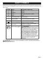
20 Volt Lithium-Ion
Hammer Drill
241-0413
OPERATOR’S MANUAL
CAUTION: To Reduce The Risk Of Injury, User Must Read And
Understand The Operator’s Manual. Save These Instructions For
Future Reference.
For questions / comments, technical assistance or repair parts –
Please Call Toll Free: 1-866-917-4374. (M-F 8am – 6pm EST.)
Page 1
table of contents
Safety Symbols. . . . . . . . . . . . . . . . . . . . . . . . . . . . . . . . . . . . . . . . . . . . . . . . . . . . . . . . . . Page 2
Safety Instructions. . . . . . . . . . . . . . . . . . . . . . . . . . . . . . . . . . . . . . . . . . . . . . . . . . . . . . . Page 3
Overview/Specifications . . . . . . . . . . . . . . . . . . . . . . . . . . . . . . . . . . . . . . . . . . . . . . . . . . Page 7
Assembly . . . . . . . . . . . . . . . . . . . . . . . . . . . . . . . . . . . . . . . . . . . . . . . . . . . . . . . . . . . . . . Page 8
Operation . . . . . . . . . . . . . . . . . . . . . . . . . . . . . . . . . . . . . . . . . . . . . . . . . . . . . . . . . . . . . . Page 9
Maintenance. . . . . . . . . . . . . . . . . . . . . . . . . . . . . . . . . . . . . . . . . . . . . . . . . . . . . . . . . . . Page 15
Troubleshooting. . . . . . . . . . . . . . . . . . . . . . . . . . . . . . . . . . . . . . . . . . . . . . . . . . . . . . . . Page 16
Warranty. . . . . . . . . . . . . . . . . . . . . . . . . . . . . . . . . . . . . . . . . . . . . . . . . . . . . . . . . . . . . . Page 18
safety symbols
Some of these following symbols may be used on this tool. Please study them and learn their
meaning. Proper interpretation of these symbols will allow you to operate the tool better and
more safely.
Symbol
Name
Designation / Explanation
V
Volts
Voltage
A
Amperes
Current
Hz
Hertz
Frequency (cycles per second)
W
Watts
Power
∿
Alternating current
Type of current
�
Direct current
Type of characteristic of current
no
No-load speed
Rotational speed at no load
Class II construction
Double insulated construction
Per minute
Revolutions, strokes, surface speed
orbits, etc., per minute
.../min
Wear safety goggles
WARNING: The operation of any
power tool can result in foreign objects
being thrown into your eyes, which can
result in severe eye damage. Before
beginning power tool operation, always
wear safety goggles or safety glasses
with side shields and a full-face shield
when needed. We recommend a Wide
Vision Safety Mask for use over eyeglasses or standard safety glasses with
side shields. Always use eye protection
which is marked to comply with
ANSI Z87.1.
WARNING: To ensure safety and reliability, all repairs should be performed by a
qualified service technician.
Page 2
safety INSTRUCTIONS
The purpose of safety symbols is to attract your attention to possible dangers. The
safety symbols and the explanations with them deserve your careful attention and
understanding. The symbol warnings do not, by themselves, eliminate any danger. The
instructions and warnings they give are no substitutes for proper accident prevention
measures.
WARNING: Be sure to read and understand all safety instructions in this manual,
including all safety alert symbols such as “DANGER,” ”WARNING,” and “CAUTION”
before using this tool. Failure to follow all instructions listed below may result in
electric shock, fire, and/or serious personal injury.
SYMBOL MEANING
SAFETY ALERT SYMBOL: Indicates DANGER, WARNING, OR CAUTION.
May be used in conjunction with other symbols or pictographs.
DANGER: Indicates an imminently hazardous situation, which, if not avoided,
will result in death or serious injury.
WARNING: Indicates a potentially hazardous situation, which, if not avoided,
could result in death or serious injury.
CAUTION: Indicates a potentially hazardous situation, which, if not avoided,
could result in minor or moderate injury.
NOTICE: (Without Safety Alert Symbol) Indicates a situation that may result in property
damage.
SAVE THESE INSTRUCTIONS!
Page 3
safety INSTRUCTIONS
WARNING:
Read all safety
warnings and instructions!
Failure to follow the warnings and
instructions may result in electric shock,
fire and/or serious injury. Save all
warnings and instructions for future
reference.
The term power tool in the warnings refers
to your mains-operated (corded) power tool
or battery-operated (cordless) power tool.
WARNING: Risk of fire and electric
shock. Dry location use only. Do not
expose to rain. Risk of injury.
Work area safety
1. Keep the work area clean and well lit.
Cluttered or dark areas invite accidents.
2. Do not operate power tools in
explosive atmospheres, such as in the
presence of flammable liquids, gases
or dust. Power tools create sparks which
may ignite the dust or fumes.
3. Keep children and bystanders away
while operating a power tool. Distractions
can cause you to lose control.
Electrical safety
1. Power tool plugs must match the outlet.
Never modify the plug in any way. Do not
use any adapter plugs with earthed
(grounded) power tools. Unmodified plugs
and matching outlets will reduce the risk of
electric shock.
2. Avoid body contact with earthed or
grounded surfaces such as pipes, radiators,
ranges and refrigerators. There is an
increased risk of electric shock if your
body is earthed or grounded.
3. Do not expose power tools to rain or
wet conditions. Water entering a power tool
will increase the risk of electric shock.
4. Do not abuse the cord. Never use the
cord for carrying, pulling or unplugging the
power tool. Keep the cord away from heat,
oil, sharp edges or moving parts. Damaged
or entangled cords increase the risk of
electric shock.
5. When operating a power tool outdoors,
use an extension cord suitable for outdoor
use. Use of a cord suitable for outdoor use
reduces the risk of electric shock.
6. If operating a power tool in a damp
location is unavoidable, use a ground-fault
circuit interrupter (GFCI) protected supply.
Use of a GFCI reduces the risk of electric
shock.
Personal safety
1. Stay alert, watch what you are doing
and use common sense when operating
a power tool. Do not use the tool while
tired or under the influence of drugs,
alcohol, or medication. A moment of
inattention while operating power tools
may result in serious personal injury.
2. Use personal protective equipment.
Always wear eye protection. Protective
equipment such as a dust mask, non-skid
safety shoes, hard hat, or hearing
protection, used for appropriate conditions,
will reduce personal injuries.
3. Prevent unintentional starting. Ensure
that the switch is in the off-position
before connecting to the power source
and/or battery pack, picking up or carrying
the tool. Carrying power tools with your
finger on the switch or energizing power
tools that have the switch on invites
accidents.
4. Remove any adjusting key or wrench
before turning the power tool on. A wrench
or a key left attached to a rotating part of
the power tool may result in personal injury.
5. Do not overreach. Keep proper footing
and balance at all times. This enables
better control of the power tool in
unexpected situations.
Page 4
safety INSTRUCTIONS
6. Dress properly. Do not wear loose
clothing or jewelry. Keep your hair,
clothing and gloves away from moving
parts. Loose clothes, jewelry or long hair
can be caught in moving parts.
7. If devices are provided for the
connection of dust extraction and
collection facilities, ensure that these
are connected and properly used. Use
of these devices can reduce dust-related
hazards.
6. Keep cutting tools sharp and clean.
Properly maintained cutting tools with sharp
cutting edges are less likely to bind and
are easier to control.
7. Use the power tool, accessories, tool
bits etc. in accordance with these
instructions, taking into account the
working conditions and the work to be
performed. Use of the power tool for
operations different from those intended
could result in a hazardous situation.
USE AND CARE of the
power tools
BATTERY TOOL USE AND CARE
1. Do not force the power tool. Use the
correct power tool for your application.
The correct power tool will do the job
better and more safely at the rate for
which it was designed.
2. Do not use the power tool if the switch
does not turn it on and off. Any power tool
that cannot be controlled with the switch is
dangerous and must be repaired.
3. Disconnect the plug from the power
source and/or the battery pack from
the power tool before making any
adjustments, changing accessories, or
storing power tools. Such preventive
safety measures reduce the risk of starting
the power tool accidentally.
4. Store idle power tools out of the reach
of children and do not allow persons
unfamiliar with the power tool or these
instructions to operate the power tool.
Power tools are dangerous in the hands of
untrained users.
5. Maintain power tools. Check for
misalignment or binding of moving parts,
breakage of parts and any other condition
that may affect the power tool’s operation.
If damaged, have the power tool repaired
before use. Many accidents are caused by
poorly maintained power tools.
Page 5
1. Recharge only with the charger
specified by the manufacturer. A charger
that is suitable for one type of battery
pack may create a risk of fire when used
with another battery pack.
2. Use power tools only with specifically
designated battery packs. Use of any other
battery packs may create a risk of injury and
fire.
3. When the battery pack is not in use,
keep it away from other metal objects,
such as paper clips, coins, keys, nails,
screws or other small metal objects that
can make a connection from one terminal
to another. Shorting the battery terminals
together may cause burns or a fire.
4. Under abusive conditions, liquid may
be ejected from the battery; avoid contact.
If contact accidentally occurs, flush with
water. If liquid contacts eyes, also seek
medical help. Liquid ejected from the
battery may cause irritation or burns.
Service
1. Have your power tool serviced by a
qualified repair person using only identical
replacement parts. This will ensure that the
safety of the power tool is maintained.
safety INSTRUCTIONS
SPECIFIC SAFETY RULES FOR
CORDLESS HAMMER DRILL
1. Use only with the batteries and charger
listed below.
Battery pack
Charger
252-8024
252-8028
252-8032
252-8033
252-8029
252-8036
252-8037
2. Hold power tools by their insulated
gripping surfaces when performing an
operation where the cutting tool may
contact hidden wiring or its own cord.
Contact with a “live” wire will also make
exposed metal parts of the tool “live” and
shock the operator.
3. Wear ear protectors when impact drilling. Exposure to noise can cause hearing
loss.
4. Use auxiliary handle(s), if supplied with
the tool. Loss of control can cause personal
injury.
5. Use protective gloves when removing
the bit from the tool, or first allow the bit
to cool down. The bit may be hot after
prolonged use.
6. Use protective gloves when operating
the tool. Protective gloves can help to keep
you from being burnt and hurt.
7. Keep your hands away from the
motor-housing vents. Hot gas comes from
the vents during operation.
8. Do not operate the tool at full-load for
more than 30 seconds, as this can cause
the motor to become too hot, which may
damage the motor.
9. Release the trigger immediately when
the screws are tightened to avoid breaking
the screw.
10. For best results, your battery tool
should be charged in a location where the
temperature is more that 41°F (5°C) but
less that 122°F (50°C). Do not store
outside or in vehicles.
Page 6
overview
Hammer/screw/drill mode selection ring
Two-speed gearbox switch
Torque adjustment ring
Ratcheting keyless chuck
Auxiliary handle
Trigger switch
LED worklight
Battery release button
Power display
button
Battery pack
Power display
Specifications
Motor
20 Volt DC
Switch
VSR (Variable Speed Reversible)
No-load speed
LO: 0-300 RPM / HI: 0-1300 RPM
Hammer
LO: 0-3900 BPM / HI: 0-16900 BPM
Clutch
24 position
Chuck
1/2” (13mm), ratcheting, single-sleeve keyless
Max torque
Hammer Drill weight (without battery)
Battery voltage
480 in. lbs.
3.06 lbs.
20 Volt DC
Charger input
120-Volts, 60Hz, AC only
Optimum charging temperature
32°F (0°C) – 122°F (50°C)
Page 7
Specifications
WARNING:
The safe use of this
product requires an understanding of the
information included on the tool and in
this operator’s manual, as well as
knowledge of the project you are
attempting. Before using this product,
familiarize yourself with all operating
features and safety rules.
Adjustable Torque
The hammer drill has 24 screw-driving
positions.
Forward/Center Lock/Reverse
The direction-of-rotation selector located
above the trigger switch changes the
direction of the bit rotation. Setting the
trigger switch in the OFF (center lock)
position helps to reduce the possibility of
accidental starting when not in use.
LED Worklight
Pressing the trigger switch illuminates the
LED worklight, located on the front of the
hammer drill. This feature provides extra
light for increased visibility.
Ratcheting Keyless Chuck
The keyless chuck allows you to
hand-tighten or release the drill bit in
the chuck jaws. The ratcheting feature
is designed to prevent the chuck from
opening during operation.
Two-Speed Gear Box
The two-speed gear box is designed for
drilling or driving at LO or HI speeds.
A slide switch is located on the top of
your hammer drill for selecting the
appropriate speed.
Variable Speed
The variable-speed trigger switch delivers
higher speed with increased trigger
pressure and lower speed with decreased
trigger pressure.
assembly
WARNING: If any part is broken or
missing, DO NOT attempt to plug in the
power cord, attach the battery or operate
the hammer drill until the broken or
missing part is replaced. Failure to do so
could result in possible serious injury.
WARNING: Do not attempt to
modify this hammer drill or create
accessories not recommended for use
with this hammer drill. Any such alteration
or modification is misuse and could result
in a hazardous condition leading to
possible serious injury.
WARNING: To prevent accidental
starting that could cause serious personal
injury, always remove the battery pack
from the hammer drill when assembling
parts.
Contents
Hammer drill, double ended bit, auxiliary
handle and Operator’s Manual.
UNPACKING
This product has been shipped completely
assembled.
1. Carefully remove the tool and any
accessories from the box. Make sure
that all of the items listed in the
packing list are included.
2. Inspect the tool carefully to make sure
that no breakage or damage occurred
during shipping.
3. Do not discard the packing material
until you have carefully inspected and
satisfactorily operated the tool.
Page 8
OPERATION
TO ATTACH BATTERY PACK
(Fig. 1)
FIG. 1
2. Depress the battery release buttons
located on the front of the battery pack
to release the battery pack.
3. Pull forward on the battery pack to
remove it from the tool.
USING THE AUXILIARY
HANDLE ASSEMBLY
WARNING: To reduce the risk of
injury, always use the auxiliary handle
when operating, hold the tool with both
hands to maximize control.
CH
DETA
H
ATTAC
1.Lock the tr
switch on the
hammer drill by placing the direction
of rotation (forward/center lock/reverse)
selector in center position.
2. Align the raised portion on the battery
pack with the grooves on the bottom
of the hammer drill, and then attach
the battery pack to the hammer drill as
shown.
3. Make sure that the latch on the battery
pack snaps into place and the battery
pack is secured to the hammer drill
before beginning operation.
NOTICE: When placing the battery pack
in the tool, be sure that the raised rib on
the battery pack aligns with the groove on
the hammer drill and the latches snap into
place properly. Improper assembly of the
battery pack can cause damage to
internal components.
TO DETACH BATTERY PACK
(FIG. 1)
1. Lock the trigger switch on the hammer
drill by placing the direction of rotation
(forward/center lock/reverse) selector in
the center position.
Page 9
The auxiliary handle must be tightened
sufficiently to resist the twisting action of
the tool if the accessory binds or stalls. Be
sure to grip the side handle at the far end
to control the tool during a stall.
The auxiliary handle can be attached to
either side for left or right hand use.
TRIGGER SWITCH (FIG. 2a)
FIG. 2a
Direction-ofrotation
selector
Variable-speed
trigger switch
To turn the hammer drill ON, depress the
trigger switch. To turn it OFF, release the
trigger switch.
OPERATION
VARIABLE SPEED (FIG. 2a)
The variable-speed trigger switch delivers
higher speed with increased trigger
pressure and lower speed with decreased
trigger pressure.
DIRECTION-OF-ROTATION
SELECTOR
(FORWARD/CENTER LOCK/
REVERSE) (FIG. 2b)
FIG. 2b
CAUTION: To prevent gear
damage, always allow the chuck to come
to a complete stop before changing the
direction of rotation.
NOTICE: The hammer drill will not run
unless the direction of rotation selector is
engaged fully to the left or right.
ELECTRIC BRAKE
To stop the hammer drill, release the
trigger switch and allow the chuck to come
to a complete stop. The electric brake
quickly stops the chuck from rotating.
This feature engages automatically when
you release the trigger switch.
RATCHETING KEYLESS CHUCK
(FIG. 3)
FORWARD REVERSE
The direction of bit rotation is reversible
and is controlled by a selector located
above the trigger switch.
With the hammer drill held in normal
operating position:
1.Position the direction of rotation
selector to the left of the tool for
forward rotation.
2.Position the direction of rotation
selector to the right of the tool for
reverse rotation.
3. Setting the switch in the OFF (center
lock) position helps reduce the
possibility of accidental starting when
not in use.
WARNING: Do not hold the chuck
body with one hand and use the power of
the hammer drill to tighten the chuck jaws
on the drill bit. The chuck body could slip
in your hand, or your hand could slip and
come in contact with the rotating bit. This
could cause an accident resulting in
serious personal injury.
FIG. 3
OPEN
Keyless chuck (Release)
GRIP
(Tighten)
Page 10
OPERATION
The hammer drill has a keyless chuck
to tighten or release the drill bits in the
chuck jaws. The arrows on the chuck
indicate which direction to rotate the
chuck body in order to GRIP (tighten) or
OPEN (release) the chuck jaws on the drill
bit. The ratcheting feature is designed
to prevent the chuck from opening during
operation.
TWO-SPEED GEAR BOX (FIG. 4)
FIG. 4
HI speed is better for drilling wood and
wood composites and for using abrasive
and polishing accessories.
NOTICE: Avoid running the hammer drill at
LO speed for extended periods of time.
Running at LO speed under constant
usage may cause the hammer drill to
become overheated. If this occurs, cool
the hammer drill by running it without a
load at HI speed.
NOTICE: Never change gears while the
tool is running. Failure to obey this
caution could result in serious damage to
the hammer drill.
SCREWDRIVING/DRILLING/
HAMMER DRILLING MODE
SELECTION (Fig. 5)
FIG. 5
Arrow
Two-speed gearbox switch
The hammer drill has a two-speed gear
box designed for drilling or driving at LO
or HI speeds. A slide switch is located on
the top of the hammer drill to select either
LO or HI speed.
When using the hammer drill in the LO
speed range, the speed will decrease and
the hammer drill will have more power and
torque. When using the hammer drill in the
HI speed range, the speed will increase
and the hammer drill will have less
power and torque. Use LO speed for high
power and torque applications and HI
speed for fast drilling or driving
applications.
Use LO speed for starting holes without
a center punch, drilling metals or plastic,
drilling ceramics, or in applications
requiring a higher torque (see below).
Page 11
Mode selection ring
To select the mode, rotate the mode
selection ring until the appropriate icon
aligns with the arrow and clicks into
position.
OPERATION
Screwdriving
Rotate the mode selection ring so the
screw symbol is aligned with the arrow.
Set the torque adjustment ring to the
appropriate number setting for the torque
desired.
Drilling
NOTICE: When the mode selection ring
is in the drill or hammer drill mode, the
clutch will not slip, regardless of the
position of the torque adjustment ring.
Rotate the mode selection ring so the drill
symbol is aligned with the arrow.
NOTICE: The torque adjustment ring may
be set on any number.
Hammer drilling
Rotate the mode selection ring so the
hammer symbol is aligned with the arrow.
ADJUSTABLE TORQUE
CLUTCH (Fig. 6)
CAUTION: Do not change the
torque setting when the tool is running.
FIG. 6
To decrease torque
Torque
adjustment
ring
To increase torque
The torque clutch can be adjusted to 24
different settings. The higher the torque
setting, the more force the hammer drill
produces to turn an object in either LO or
HI rotation speed.
When using the hammer drill for
different
driving
applications,
it
is
necessary to increase or decrease the
torque in order to help prevent the
possibility of damaging screw heads,
threads, workpiece, etc.
Adjust the torque by
torque-adjustment ring.
rotating
the
The proper setting depends on the job
and the type of bit, fastener, and material
you will be using. In general, use greater
torque for larger screws, but if the torque
is too high, the screws may be
damaged or broken.
For delicate operations, such as removing
a partially stripped screw, use a low torque
setting. For operations such as drilling
into hardwood, use a higher torque setting.
NOTICE: When adjusting the torque
clutch, make sure that the speed switch is
completely in either the LO or HI position.
Page 12
OPERATION
LED WORKLIGHT (Fig. 7)
FIG. 8b
FIG. 7
LED worklight
The LED worklight, located on the base of
the hammer drill, will illuminate when the
trigger switch is depressed. The LED
worklight will turn off when the trigger
switch is released. This provides additional
light on the surface of the workpiece for
operation in lower-light areas.
INSTALLING BITS (Fig. 8a, 8b)
FIG. 8a
OPEN
Keyless chuck (Release)
2. Open or close the chuck jaws to a point
where the opening is slightly larger than
the bit size you intend to use.
3. Insert a drill bit.
WARNING: Make sure to insert the
drill bit straight into the chuck jaws. Do
not insert the drill bit into the chuck jaws
at an angle and then tighten the chuck,
as shown in figure 8b. This could cause
the drill bit to be thrown from the hammer
drill, resulting in possible serious personal
injury or damage to the chuck.
NOTICE: Rotate the chuck body in the
direction of the arrow marked GRIP to
close the chuck jaws. Do not use a
wrench to tighten or loosen the chuck
jaws.
4. Tighten the chuck jaws securely on the
bit.
REMOVING BITS
GRIP
(Tighten)
1. Lock the trigger switch by placing the
direction of rotation selector in the OFF
(center) position.
Page 13
CAUTION: Use protective gloves
when removing the bit from the tool, or
first allow the bit to cool down. The bit
may be hot after prolonged use.
1. Lock the trigger switch by placing the
direction of rotation selector in the OFF
(center) position.
2. Open the chuck jaws.
OPERATION
NOTICE: Rotate the chuck body in the
direction of the arrow marked OPEN to
close the chuck jaws. Do not use a
wrench to tighten or loosen the chuck
jaws.
3. Remove the drill bit.
GENERAL DRILLING (Fig. 9)
FIG. 9
7. When drilling metals, use light oil on
the drill bit to keep it from overheating.
The oil will prolong the life of the bit and
increase the drilling action.
8. If the bit jams in the workpiece or if
the hammer drill stalls, stop the tool
immediately. Remove the bit from the
workpiece and determine the reason for
jamming.
NOTICE: This hammer drill is equipped
with an electric brake. When the brake is
functioning properly, sparks may be
visible through the vent slots in the
housing. This is normal and is the action
of the brake.
DRILLING MODE OPERATION
1. Check the direction of rotation selector
for the correct setting (forward or
reverse).
2. Secure the material to be drilled in a vise
or with clamps to keep it from turning as
the drill bit rotates.
3. Hold the hammer drill firmly and place
the bit at the point to be drilled.
4. Depress the trigger switch to start the
hammer drill.
5. Move the drill bit to contact the workpiece, applying only enough pressure
to keep the bit cutting. Do not force the
drill or apply side pressure to elongate a
hole. Let the tool do the work.
6. When drilling hard, smooth surfaces, use
a center punch to mark the desired
location of the hole. This will prevent the
drill bit from slipping off-center as the
hole is started.
1. Select the desired speed to match the
planned operation.
2. For wood drilling, use twist bits, spade
bits, power auger bits or hole saws.
Begin drilling at a very low speed to
prevent the bit from slipping off of the
starting point and increase the speed
as the drill bit bites into the material.
When drilling “through” holes, place a
block of wood behind the workpiece to
prevent ragged or splintered edges on
the back side of the hole.
3. For metal drilling, use high speed steel
twist drill bits. Begin drilling at a very low
speed to prevent the bit from slipping
off of the starting point. Maintain a
speed and pressure which allows
cutting without overheating the bit. Use
light oil on the drill bit to keep it from
overheating; the oil will prolong the life
of the bit and increase the drilling action.
4. If the hammer drill stalls, it is usually
because it is being overloaded.
Release the trigger switch immediately,
remove the drill bit from work, and
determine the cause of stalling.
Page 14
OPERATION
5. Keep the motor running when pulling
the bit back out of the drilled hole. This
will prevent jamming.
HAMMER DRILLING MODE
OPERATION
WARNING: Always wear safety
goggles or safety glasses with side
shields during power tool operation or
when blowing dust. If the operation is
dusty, also wear a dust mask.
SCREWDRIVER OPERATION
1. When hammer drilling, use just enough
force on the hammer to keep it from
bouncing excessively. Too much force
will cause slower drilling speeds,
overheating and a lower drilling rate.
2. Do not exert side pressure on the
bit when drilling, as this will cause
clogging of the bit flutes and reduced
drilling speed.
3. When drilling deep holes, if the drill
speed starts to drop off, pull the bit
partially out of the hole with the tool still
running to help clear debris from the
hole.
4. For masonry, use carbide-tipped bits or
masonry bits. A smooth, even flow of
dust indicates the proper drilling rate.
1. Select the desired speed/torque range
to match the planned operation.
2. Attach the desired fastener accessory
into the chuck.
3. Make a few practice runs in a scrap
piece before working.
maintenance
GENERAL MAINTENANCE
WARNING: To avoid personal
injury, always remove the battery pack
from the tool when cleaning or performing
any maintenance.
The tool may be cleaned most effectively
with compressed dry air. Always wear
safety goggles when cleaning tools with
compressed air.
Avoid using solvents when cleaning plastic
parts. Most plastics are susceptible to
damage from various types of commercial
solvents and may be damaged by their
use. Use clean cloths to remove dirt, dust,
oil, grease, etc.
Page 15
WARNING: When servicing, use
only identical replacement parts. Use of
any other parts may create a hazard or
cause product damage. To ensure safety
and reliability, all repairs should be
performed by a qualified service
technician.
maintenance
CHUCK REMOVAL (Fig. 10)
FIG. 10
Mallet
2.Open the chuck jaws. Using a
screwdriver, remove the chuck screw
by turning it in a clockwise direction.
3. Insert a 5/16-in. or larger hex key into
the chuck of the hammer drill and
tighten the chuck jaws securely.
4. Tap the hex key sharply with a mallet
in a anti-clockwise direction. This will
loosen the chuck for easy removal.
5. Attach a new chuck to the spindle and
tighten the chuck screw.
Hex Key
Chuck jaws
The chuck can be removed and replaced
with a new one.
1. Lock the trigger switch by placing the
direction of rotation selector in the
center position.
troubleshooting
PROBLEM
CAUSE
SUGGESTED CORRECTIVE ACTION
The hammer drill
does not work.
1. Battery is depleted.
1. Charge the battery.
Bit cannot be
installed.
1. Sleeve is not released.
1. Release the sleeve.
2. Bit does not fit the sleeve.
2. Use a suitable adapter.
1. Be sure the cooling vents
are free from dust and
obstacles.
1. Clean and clear the vents. Do not
cover with hand during operation.
The motor is
overheating.
Page 16
notes
Page 17
20 Volt Lithium-Ion Hammer Drill
WARRANTY
90-DAY MONEY BACK GUARANTEE:
This MASTERFORCE® brand power tool carries our 90-DAY Money Back
Guarantee. If you are not completely satisfied with your MASTERFORCE® brand
power tool for any reason within ninety (90) days from the date of purchase, return
the tool with your original receipt to any MENARDS® retail store, and we will provide
you a refund – no questions asked.
3-YEAR LIMITED WARRANTY:
This MASTERFORCE® brand power tool carries our famous No Hassle 3-Year
Limited Warranty to the original purchaser.
If, during normal use, this
MASTERFORCE® power tool breaks or fails due to a defect in material or
workmanship within three (3) years from the date of original purchase, simply bring
this tool with the original sales receipt back to your nearest MENARDS® retail store.
At its discretion, MASTERFORCE® agrees to have the tool or any defective part(s)
repaired or replaced with the same or similar MASTERFORCE® product or part
free of charge, within the stated warranty period, when returned by the original
purchaser with original sales receipt. Not withstanding the foregoing, this limited
warranty does not cover any damage that has resulted from abuse or misuse of
the Merchandise. This warranty: (1) excludes expendable parts including but not
limited to blades, brushes, belts, bits, light bulbs, and/or batteries; (2) shall be void
if this tool is used for commercial and/or rental purposes; and (3) does not cover any
losses, injuries to persons/property or costs. This warranty does give you specific
legal rights and you may have other rights, which vary from state to state. Be
careful, tools are dangerous if improperly used or maintained. Seller’s employees
are not qualified to advise you on the use of this Merchandise. Any oral
representation(s) made will not be binding on seller or its employees. The rights
under this limited warranty are to the original purchaser of the Merchandise and may
not be transferred to any subsequent owner. This limited warranty is in lieu of all
warranties, expressed or implied including warranties or merchantability and fitness
for a particular purpose. Seller shall not be liable for any special, incidental, or
consequential damages. The sole exclusive remedy against the seller will be for the
replacement of any defects as provided herein, as long as the seller is willing or
able to replace this product or is willing to refund the purchase price as provided
above. For insurance purposes, seller is not allowed to demonstrate any of these
power tools for you.
For questions / comments, technical assistance or repair parts – Please Call Toll
Free at: 1-866-917-4374. (M-F 8am – 6pm EST)
SAVE YOUR RECEIPTS
THIS WARRANTY IS VOID WITHOUT THEM
Page 18
© 2012 Menard, Inc., Eau Claire, WI 54703
Page 20
09/2012