1
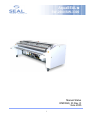
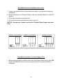
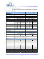
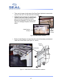
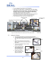
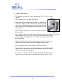
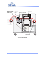
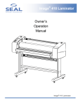
AquaSEAL Seal Brands … the finishing touch. SW-2600/SW-3300 Owner Operation Manual Important: Read and understand all safety information before operating. ©Copyright SEAL® Graphics 2002, 2004 All rights are reserved. No part of the document may be photocopied, reproduced, or translated to another language without the prior written consent of SEAL® Graphics. The information contained in this document is subject to change without notice and should not be construed as a commitment by SEAL® Graphics. SEAL® Graphics assumes no responsibility for any errors that may appear in this document. Nor does it make expressed or implied warranty of any kind with regard to this material, including, but not limited to, the implied warranties of merchantability and fitness for a particular purpose. SEAL® Graphics shall not be liable for incidental or consequential damages in connection with, or arising out of the furnishing, performance, or use of this document and the program material, which it describes. Trademarks Credits SEAL® is a registered trademark of SEAL Graphics. Image® is a registered trademark of SEAL Graphics. AquaSEAL® is a registered trademark of SEAL Graphics. ProSEAL® is a registered trademark of SEAL Graphics. AquaSEAL SW-2600/SW-3300 Seal Brands … the finishing touch. Manual Status OMSW26_33 Rev. D June 2005 I Introduction Manual Overview This manual is intended for the user of the AquaSEAL™ SW-2600 or 3300. Read this manual carefully before starting the machine. The AquaSEAL™ SW-2600 & 3300 are liquid coaters used to coat printed substrate with a protective sealant. The unit will accommodate medium, large, and grand format substrate. This manual contains information for correct installation, operation and maintenance of the machine. The substrate is threaded through the sealant applicator mechanism, under a drying assembly, and onto a take-up roller. During the operation, the liquid coater applies sealant onto the printed graphics (base substrate) and then cures and dries it before winding the substrate onto a take-up roller. It also contains important instructions on how to prevent accidents, personal injury and/or serious damage prior to or during operation of the machine. Familiarize yourself with the functioning and operation of this machine and strictly observe the directions given. The results can be controlled by a combination of speed settings, unwind tension and temperature control. A trained operator is required to adjust these settings in combination for best results. If you have any questions, please do not hesitate to contact us. The address and phone numbers are listed in Section 8 Technical Support. Topics Covered in This Manual Section 1. Safety Information: An explanation of equipment, environmental and operating safety issues. Section 2. Features & Control Panel: AquaSEAL SW-2600 and SW-3300 features explanations and Control Panel layout and usage. Section 3. Specifications: Lists the general specifications, requirements, and capacities. Section 4. Installation and Set-up: Outlines procedures for unpacking and setting up the coater. Section 5. Operating Procedures: Outlines start-up and job processing steps. Section 6. Maintenance: Outlines job process cleaning, 24-hour cleaning, and regular maintenance care and cleaning. Section 7. Glossary: Lists and defines terms used in this manual. Section 8. Technical Support: Contact information for Aqua SEALTM SW-2600 and SW-3300 technical issues and questions. In this manual you will find four (4) levels of flagged warnings or notes: DANGER! INDICATES AN IMMINENTLY HAZARDOUS SITUATION WHICH, IF NOT AVOIDED, COULD RESULT IN DEATH OR SERIOUS INJURY. WARNING! INDICATES A POTENTIALLY HAZARDOUS SITUATION WHICH, IF NOT AVOIDED, COULD RESULT IN DEATH OR SERIOUS INJURY. CAUTION! INDICATES A POTENTIALLY HAZARDOUS SITUATION WHICH, IF NOT AVOIDED, COULD RESULT IN MINOR OR MODERATE INJURY. NOTE: The Note message is used to give operational information and useful tips. II Warranty SEAL® Graphics warrants to the original consumer purchaser that each new SEAL® Image® Coater, which proves defective in materials or workmanship within the applicable warranty period, will be repaired or, at our option, replaced without charge. This is provided that only AquaSeal liquid coatings or Seal approved products are used. Effective November 1, 2002 the applicable warranty period for new equipment shall be one year (parts), six months (labor and rollers) from date of purchase. This warranty extends to and is enforceable by only the original consumer purchaser, and only for the period (during the applicable term), which the product remains in the possession of the original consumer purchaser. "Original consumer purchaser" means the person who first purchased the product covered by this warranty other than for purpose of resale. This warranty does not apply if it is found that at any time the equipment has not been used for its intended purpose or coating other than AquaSeal or Seal approved coating products have been use at any time in the machine. Effective November 1, 2002 the applicable warranty period for Refurbished Equipment shall be ninety days (parts and labor, excluding rollers). Rollers are not covered under warranty. The applicable warranty period for Demo Equipment shall vary, not exceeding the maximum warranty period stated herein. All Demo Equipment comes with a specific warranty, which will be stated at the time of purchase. If warranty period is not detailed in writing, there is no remaining warranty. Please ask your dealer, distributor, or sales representative for details. NOTE: Used Equipment that has not been refurbished to Seal Graphics criteria, is sold on an “AS IS” basis with No Warranty. For more information regarding this warranty, please contact your distributor. CAUTION! Any unauthorized changes or modifications to this unit without our prior written approval will void the user’s warranty and will transfer health and safety obligations to the user CAUTION! Changes or modifications to this unit not expressly approved by the party responsible for compliance could void the user's authority to operate the equipment NOTE: This equipment has been tested and found to comply with the limits for a class "A" digital device, pursuant to part 15 of the FCC rules. These limits are designed to provide reasonable protection against harmful interference when the equipment is operated in a commercial environment. This equipment generates, uses, and can radiate radio frequency energy and, if not installed and used in accordance with Owner’s Manual, may cause harmful interference to radio communications. Operation of this equipment in a residential area is likely to cause harmful interference in which case the user will be required to correct the interference at their expense. III Table of Contents Manual Status ……………………………………......................................................... I Introduction & Manual Overview ……………..……….............................................. II Warranty ……………………………………………….................................................... III Table of Contents ………………………………………………………………………….. IV,V ELECTRICAL INSTALLATION INSTRUCTIONS ………………………………………. Vl General Safety Information…………………………………………………………………. VIl CONTENT 1. Safety Information 1.1. Personnel Safety Equipment……………………………….………..….......…... 1.2. Environmental………………………………………………………….…………... 1.3. Electrical ………………………………………………………………………... ... 1.4. Mechanical …………………………………………………………………………. 1.5. Chemical ………………………………………………………………………….... 1.6. Pneumatics ………………………………………………………………………… 1.7. Warning Decals ……………………………………………………………….…… 1.8. Emergency Stop Buttons …………………………………………………………. 1.9. Do’s and Don’ts ……………………………………………………………………. 1 1 1 2 2 2 3 4 4 2. Features & Control Panel Features …………………………………………………………………………………. 2.1 AccuCure Feedback System …………………………………………. 2.2 Brake Tension Control ………………………………………………... 2.3 Main Circuit Breaker …………………………………………………... 2.4 Connections 2.4.1 Power ……………………………………………………….. 2.4.2 Compressed Air ……………………………………………. 2.5 Cooling Fan ………………………………………………………......... 2.6 Draw-Down Applicator……………….. ………………………………. 2.7 Dryer Panel …………………………………………………………….. 2.8 Emergency Stop Buttons ……………………………………………... 2.9 AccuCure IR Heat Sensor……....…………………………………….. 2.10 Photo Eyes ……………………………………………………………... 2.11 Sealant Distribution Valves ……...…………………………………… 2.12 Sealant Drain Pan ……………………………………………………... 2.13 Sealant Pump ………………………………………………………….. 2.14 Sealant Tank ……………………………………………………........... 2.15 Take-Up Roller ………………………. ……………………………….. 2.16 Unwind Roller ………………………………………………………….. Control Panel ……………………………………………………………………………. 2.17 Control Panel Switch ……………………………………………......... 2.18 Pre-Heat/Run Switch …………………………………………………. 2.19 Temperature Control Display ………………………………………… 2.20 Dryer Panel Switch ………………………………………................... IV 5-6 7 7 7 7 7 8 8 8 8 9 9 9 9 10 10 10 10 11 12 12 12 12 2.21 2.22 Speed Control Display………………………………………….……... 13 Sealant Pump Switch………………. ………………………………… 13 3. Specifications ………………………………………………………………………..... 14 3.2. Identification …………………………………………………………………….…. 15 3.3. Accessories ……………..…….…………………………………………………... 15 4. Installation and Set-up 4.1. Unpacking and Assembly……………..………………………………………….. 15-16 4.2. Installation, Set-up and Training Requirements ……………………………….. 17 5. Operating Procedures 5.1. General Outline …………………………………………………..………………. 18 5.2. Tools & Supplies Required…………………………..………..…………………. 18 5.3. Pre-heating the Coater …..………………………………………………………. 18 5.4. Loading Sealant ………………………………………………...………………… 19 5.5. Priming the Sealant Pump……………………………………..………………… 19 5.6. Loading the Substrate…..………………………………………………………... 20-21 5.7. Webbing Coater …………………………………………………….…………….. 22-23 5.8. Running the Coater in Speed Mode… ….………………………………..…….. 24-25 5.9. Running the Coater in Temp Mode…..…………………………………...…….. 25-26 5.10. Process Control Data Sheet ……………..……………………………………… 26-27 5.11. Unloading Substrate ………………………………..……………………..……... 28 6. Maintenance 6.1. Cleaning between Runs………………………………………………………….. 6.2. Periodic Maintenance………. ……………………………………………………. 6.3. Trouble Shooting……………………….………………………………………….. 7. Glossary ………………………………………………………………………………… 28 28-29 30-32 33 8. Technical Support …………………………………………………………………….. Back Cover Vl V SuperWide Electrical Installation Instructions 1. Power cord installation must be performed according to local electrical codes and ordinances. 2. Before opening door to Electrical Cabinet, make sure Interlock Switch is in the OFF position. 3. For wiring information see chart below. 4. For machine electrical specifications, refer to page 14. NOTICE: Ground wire of power cord must be 2 inches (50mm) longer than other wires. N LT. BLUE L3 BLACK G R N /Y E LLO W BLACK GREEN PE E u ro p e L2 L1 BROWN PE 3 -P H A S E L3 L2 L1 L2 WHITE GREEN BLUE PE U .S ./ C a n a d a RED L1 3 -P H A S E BLACK U .S ./ C a n a d a WHITE 1 -P H A S E SuperWide Installation Technical Support Tips 1. Before applying power to machine make sure all electrical switches are in their OFF position and that the source of power is properly secured to protect installation electrician. Vl General Safety Information Do not operate the machine until it is connected to the proper power source. Refer to the electrical installation instructions. It is strongly recommended that the machine is fed from an “Earth Leakage” protected electrical outlet – if in doubt, please contact Hunt Technical Services (contact details in the “Miscellaneous” section at the rear of the manual) or consult a license electrician. Familiarize yourself with the layout of the Control Panel, and with the operation of the sealant delivery system. Do not wear loose clothing, and make sure hair is tied back to avoid becoming entangled in the machine. Comply with all safety warning signs, labels, and instructions. Operators should be trained on the proper use of the machine and all safety procedures. Provide fresh water, clean towels and rubber gloves for use doing cleanup. It is advisable to wear eye protection when filling/emptying sealant tank. Always provide an approved emergency eyewash station adjacent to the machine. Machine Unpacking Instructions 1. Remove screws from top panels and set panels aside. 2. The two (2) shipping straps can now be removed by unscrewing the nuts at the base of crate, or by releasing the ratchet mechanism. 3. Remove screws from caster stop blocks, release the brake at all four (4) casters. Machine can now be carefully rolled off skid. (Note: After placing machine in vicinity of operational position, set caster brakes to keep machine in place.) VII Section 1 - Safety Information The owner of the machine is responsible for safely operating the machine. The owner therefore is obliged to familiarize operating personnel with the contents of this manual and make them aware of all possible hazards. NOTE: When using any equipment, always follow the manufacturers’ instructions for safe operation. In case of emergency, please telephone: +44 (0)1268 530 331 Europe, or (800) 486-6502 USA 1.1 Personnel Safety Equipment Heat resistant gloves recommended Safety glasses required Eye wash station recommended WARNING: AVOID CONTACT WITH HEAT SOURCE. FAILURE TO AVOID CONTACT WITH HEAT SOURCES OR HOT SURFACES MAY CAUSE BURNS. 1.2 Environmental Place the unit in a well-lit, dust-free, and adequately ventilated work area with plenty of room to process jobs. The coater should be level. With heating elements in the unit there is always an issue with fire. Make certain there are fire extinguishers close by. An extinguisher rated “Class C” is required for fires involving energized electrical equipment. WARNING: RISK OF FIRE OR EXPLOSION. DO NOT USE FLAMMABLE OR SOLVENT BASED LIQUIDS. 1.3 Electrical Use a Lock out/Tag out on circuit breakers or “Power On” switches when performing repairs or maintenance. Operation of the unit with the electrical circuitry exposed is dangerous (i.e. with side panel doors open). Side panel doors should remain locked, unless repairs are being done by a licensed electrician or qualified maintenance personnel, with knowledge of the Aqua SEALTM SW-2600 or SW-3300. 1 NOTE: It is strongly recommended that the unit is fed from an GFCI – if in doubt, please contact Seal Graphics Technical Services (listed at rear of manual) or consult a licensed electrician. 1.4 1.5 Mechanical Avoid reaching in or around the pinch points and hot spots when the unit is running (see Section 1.7). Operating the unit outside the operational instructions of this manual may result in injury, damage to the unit, and/or voiding the warranty. Chemical When handling any chemical products, read the manufacturers’ container labels and the Material Safety Data Sheets (MSDS) for important health, safety, and environmental information. To obtain MSDS Sheets for AquaSEAL™ Products, please call your local distributor. CAUTION: ALWAYS OBSERVE MANUFACTURERS’ RECOMMENDATIONS WHEN HANDLING CHEMICALS. 1.6 Pneumatics There can be up to 125psi (pounds per square inch) of air compression in the unit at any one time. A visual check of the system before start-up is recommended. A periodical check of the system’s integrity is required. The maximum air compression is 125psi; the recommended is 90100psi @ 3cfm. 2 1.7 Warning Decals Operator should be familiar with the locations and type of warning decals that are on the unit. Back-Side Both Ends Front-Side Both Ends Photo Eyes 6 PL Both Tanks Figure 1: Locations of Warning Decals Pinch Decal Areas to avoid the mechanism from pinching or pulling. Warning Decal Fire or Explosion Risk (Solvent Tank and Dryer Panel) Hot-Spot Decal Areas to avoid getting burned or combustion. Danger Decal Electrical Danger (Dryer Panel) Figure 2: Types of Warning Decals 3 Electrical Decal Areas to avoid getting an electrical shock. 1.8 Emergency Stop Buttons There are three red Emergency Stop Buttons, located prominently in front on both ends of the unit and on top of the unit at the center. When pressed, all power is shut down, and all pneumatic assemblies return to their safe state (see Section 2.8). Emergency Stop Buttons Figure 3: Emergency Stop Button Locations 1.9 DO’s and DON’Ts DO comply with all safety warning signs, labels, and instructions. DO train operators on the proper use of the machine and all safety procedures. DO familiarize operators with the layout of the Control Panel and with the operation of the sealant delivery system. DO provide fresh water, clean towels and rubber gloves for use during cleanup. DO wear eye protection. DO provide an approved emergency eyewash station adjacent to the machine. 4 DO NOT operate unit until it is connected to the proper power source. DO NOT place unit near open flames. DO NOT wear loose clothing or loose jewelry, and contain loose hair to avoid becoming entangled with moving parts of the machine. DO NOT reach into pinch areas or touch hot spots. Section 2 - Features & Control Panel 12 13 11 11 14 1 2 3 4 5 6 10 7 8 9 Figure 4: SW-2600 & SW-3300 Features Front View 5 11 22 21 20 19 18 17 16 Figure 5: SW-2600 & SW-3300 Features Back View DESCRIPTION Brake Tension Control – Section 2.2 Unwind Roller – Section 2.16 Sealant Distribution Valves – Section 2.11 Draw-Down Applicator – Section 2.6 Web Idler Roller – Section 5.7 Sealant Pump – Sections 2.13 Sealant Drain Pan - Section 2.12 Sealant Tank – Sections 2.14 Locking Castor Cabinet Lock - Section 1.3 Photo Eye – Section 2.10 Emergency Stop Button – Sections 1.8 & 2.8 Meyer Bar Assembly (optional accessory) - Section 3.3 Control Panel – Sections 2.17 – 2.22 Identification Label – Section 3.2 Power Connection – Section 2.4.1 Main Circuit Breaker Switch – Sections 2.3 Cooling Fans – Section 2.5 Take-Up Roller – Section 2.15 Compressed Air Connection – Section 2.4.2 AccuCure IR Heat Sensor (on Slide Rail) – Section 2.9 Dryer Panel – Section 2.7 15 ITEM NO. 1 2 3 4 5 6 7 8 9 10 11 12 13 14 15 16 17 18 19 20 21 22 6 2.1 AccuCure Feed-back System The AccuCure Feed-back System is a PLC-based control system that utilizes sensors and feedback loop to control coater throughput. The system allows the operator to select operating modes: (1) TEMP Mode – an infrared temperature sensor on the back of the Dryer Panel is used to monitor the substrate temperature (2) SPEED Mode – an encoder reads the revolution speed on the Web Idler Roller as it is turned by substrate passing over it. 2.2 Brake Tension Control The Brake Tension Control knob is used to provide back tension on the substrate during operation. The Brake Tension Control knob increases or decreases braking pressure on the Unwind Roller. Turning the knob clockwise adds braking pressure and counter-clockwise reduces braking pressure. Figure 6: Brake Tension Control 2.3 Main Circuit Breaker Switch The Main Circuit Breaker Switch controls all ON/OFF power coming to the machine. 60 Amp Single Phase 50 Amp Three Phase 30 Amp Three Phase Figure 7: Circuit Breakers WARNING: DO NOT OPEN CABINET DOORS UNTIL THE MAIN CIRCUIT BREAKER SWITCH IS TURNED OFF. 2.4 Connections 2.4.1 Power Connection - This is where the unit connects to your power source (see Section 3 for Specifications). 2.4.2 Compressed Air Connection - The connection where an outside source for compressed air is connected (see Section 3 for Specifications). 7 2.5 Cooling Fans The Cooling Fan assembly (located beneath the Take-Up Roller) contains fans that cool the substrate before it rolls on the Take-Up Roller. The Cooling Fan Assembly automatically switches on when the machine is put into RUN mode. 2.6 Draw-Down Applicator The Draw-Down Applicator is used to apply and smooth the sealant onto the surface of the substrate. The Draw-Down Applicator is automatically lowered when the machine is put into RUN mode, and will rise when not in RUN mode. 2.7 Dryer Panel The Dryer Panel is constructed of two infrared heaters used to dry and cure the sealant, as the substrate passes underneath. The Dryer Panel is in the DOWN position only if all the following conditions apply: The machine is in RUN mode. The Dryer Panel Switch on the Control Panel is set to DOWN. The Run Drive is ON. There is no obstruction blocking any of the Photo Eyes. NOTE: The Dryer Panel has fans in the top of it that force air through perforations in the face of the heaters. These fans are used to push humidity away from the substrate as it passes underneath the Dryer Panel. IT IS VERY IMPORTANT THAT THE FANS REMAIN UNOBSTRUCTED. 2.8 Emergency Stop Buttons There are three red Emergency Stop Buttons. When any of the three buttons are pressed, all control power shuts down, and the pneumatically controlled Dryer Panel and Draw-Down Applicator return to UP position. The machine cannot be used again until the Emergency Stop Buttons are reset by twisting the button that was initially pressed one-quarter (¼) turn clockwise. Resetting the Emergency Stop Buttons returns the coater to an initial power ON stage. 8 2.9 AccuCure IR Heat Sensor The AccuCure IR Heat Sensor is located on the slide rail mounted to the back of the Dryer Panel. The sensor reads the surface temperature of the substrate as it leaves the Dryer Panel. The temperature readings can be viewed on the main operating screen of the Control Panel. NOTE: The location of the AccuCure IR Heat Sensor can be adjusted different substrate sizes, within up to 12” of either side. Figure 8: AccuCure IR Heat Sensor 2.10 Photo Eyes The coater has three (3) sets of Photo Eyes: the Draw-Down Applicator set is at the front of the coater, and the other two sets of photo eyes are in front and behind the Dryer Panel. Both the Draw-Down Applicator and Dryer Panel operate using pneumatic cylinders that lift up to web the machine and draw down to run substrate. The Photo Eyes are a safety feature that will raise the assemblies when the beam is crossed. The Photo Eyes are active for 5 seconds upon initiation of lowering the Draw-Down Applicator and/or Dryer Panel. Once these assemblies are lowered into position, the safety hazard is removed and the Photo Eyes become inactive during operation of the coater. If a Photo Eye is blocked while the Dryer Panel is lowering, the Dryer Panel Switch must be reset to the UP position and then back to DOWN position to lower the Dryer Panel again. 2.11 Sealant Distribution Valves The Sealant Distribution Valves control the distribution of coating across the substrate as it passes underneath. Figure 9: Sealant Distribution Valves 2.12 Sealant Drain Pan The Sealant Drain Pan takes over-flow sealant and drains it into the Sealant Tanks. 9 10 2.12 Sealant Pump The Sealant Pump circulates sealant through the coating system. 2.13 Sealant Tank (single or dual tank options, dual tank option as shown in Figure 10) The Sealant Tank capacity is 37 Liters (10 US gallons). Two different coatings can be put into the two tank system (if equipped) to run one after the other. Sealant Flow Main Drain Valve for Drain Pan Tank shut off and flow valves From Drain Pan Drain Pan Return Valve Sealant Pump Filter Sealant Tank Quick Disconnect Figure 10: Dual Tank Plumbing System shown 2.14 Take-Up Roller The Take-Up Roller collects the coated substrate as it is exiting the coater. NOTE: Both the Take-Up and the Unwind Rollers are designed to accommodate a 3" ID substrate roll that is removable. 2.15 Unwind Roller The Unwind Roller is designed to hold and feed the base substrate as it is being run through the coater. 10 Section 2 - Control Panel The Control Panel contains all the displays, controls, and indicators required to operate the coater. NOTE: The Sealant Pump switch, the Heat display/LED and the Speed Control Display are illuminate when ON. 1 2 3 4 5 6 ITEM NO. 1 2 3 4 5 6 DESCRIPTION Control Panel Switch – Section 2.17 Pre-Heat/Run Switch – Section 2.18 Temperature Control Display– Section 2.19 Dryer Panel Switch – Section 2.20 Speed Control Display – Section 2.21 Sealant Pump Switch – Section 2.22 11 2.17 Control Panel Switch Turns power ON/OFF to coater. 2.18 Pre-Heat/Run Switch The Pre-Heat/Run Switch is a toggle switch that always returns to the center, neutral position. PRE-HEAT Mode is selected to heat up the coater. Other job setup tasks can be done while the coater is in PRE-HEAT Mode; such as, adding sealant and/or webbing, while getting the Dryer Panel up to the desired temperature. Once the coater has been webbed, all controls are set and the coater has reached the set temperature, the RUN Mode can be selected. When selected, the Draw-Down Applicator will lower; however, the substrate DRIVE will not start until selected on the Speed Control Display. CAUTION: Never leave substrate unattended under the Dryer Panel when in PRE-HEAT Mode. Damage to substrate may occur. 2.19 Temperature Control Display 2.20 The Temperature Control Display shows the Dryer Panel temperature (measured by internal thermocouples) on an LED read out (Figure 12). The Dryer Panel temperature is set using this control. Adjust the temperature by holding down the star button (far left) and using the up and down arrow buttons to make changes. There is a HEAT light directly below the display that will be illuminated when the heater is ON. Figure 12: Temperature Control Display Dryer Panel Switch Dryer Panel Switch is used to raise or lower the Dryer Panel as needed. Once the coater is up to the set temperature and in RUN Mode, set the Dryer Panel Switch to the DOWN position. The Dryer Panel will not lower until the substrate DRIVE is selected on the Speed Control Display. NOTE: If the substrate DRIVE stops for any reason for more than 15 seconds, the Dryer Panel will rise to the UP position automatically. 12 2.21 Speed Control Display The Speed Control Display is a touch-screen display, and is used to set the controlling parameters of the AccuCure Feedback System. Set-Up Screen The Set-Up Screen will display when the coater is turned ON. This screen allows the user to select units, English or Metric. Once units are selected, the Main Screen will be displayed. Main Screen The PREHEAT, RUN and HEAT ON/OFF are status displays and will light when a process is active. The SPEED Mode and TEMP Mode are functioning buttons that, when touched, will activate another control screen. Speed Mode Screen The Speed Mode Screen controls starting or stopping the substrate DRIVE. To start the DRIVE, touch the RUN DRIVE button. To stop the DRIVE, touch the STOP DRIVE button. In addition, the desired speed of the substrate running through the coater can be set on this screen. The FPM/MPM (ft/min or meter/min) speed is set with the up/down arrows at this menu. The top speed displayed is the actual speed, and the bottom speed displayed is the selectable speed. Temp Mode Screen On the Temp Mode Screen you can set the desired temperature for the top of the substrate as it exits underneath the Dryer Panel (as measured by the IR sensor). To set the temperature, touch the Temp read out and a keyboard will appear, enter the temperature and touch the enter key. 13 14 2.22 Sealant Pump Switch The Sealant Pump Switch is used to control the Sealant Pump operation. Section 3 - Specifications Accu-Coat 2600 Description Unit Dimensions (uncrated) Net Weight Unit Dimensions (crated) Gross Weight ELECTRICAL Voltage Wiring Configuration 1 Phase (standard) 3 Phase (option) PNEUMATIC Pressure Requirements ENVIRONMENTAL Workspace Required Temperature Moisture Ventilation PROCESS Max Coat Width Max Coat Thickness Coating Means Standard Meyer Bar Optional Meyer Bars Max Speed Max Roll Length Max Roll Width Max Roll Weight Roll to Roll Multi Roll Capability Temperature Sealant Tank Capacity 11' x 4' x 3'11" 3.3m x 1.2m x 1.1m 1700 lbs 1700 lbs 12' 6" x 5' 1" x 4'11" 3.8m x 1.5m x 1.4m 2300 lbs 1043 kg 208230v ac 3W+ G n/a 36 amp Accu-Coat 3300 13' 2" x 4' x 3'11" 4m x 1.2m x 1.1m 1800 lbs 816 kg 14' 1" x 5' 1" x 4'11" 3.8m x 1.5m x 1.4m 2500 lbs 1134 kg 208230vac 230/400vac (European) 208230vac 208230vac 230/400vac (European) 2W+G 3NPE 3W+G 2W+G 3NPE 45 amp n/a n/a 21 amp n/a 44 amp 54 amp n/a n/a 26 amp 90 – 125psi / 6 – 8.5 bar 90 – 125psi / 6 – 8.5 bar 18’ x 16’ x 13’ 18’ x 16’ x 13’ 5.5m x 5m x 4m 5.5m x 5m x 4m 50°F - 95°F 16°C 50°F - 95°F 16°C - 35°C 35°C If located in a high moisture area – installation should be in accordance with local building codes. Clean, dust-free area with adequate circulation and ventilation. 105” 2.6m 129” 3.2m 82 micron wet 82 micron wet Meyer Bar Meyer Bar Smooth #7 Smooth #7 #11, #22, #32 #11, #22, #32 10 fpm 3m 10 fpm 3m 200’ 61m 200’ 61m 104” 2.6m 128” 302m 250 lbs 113.4kg 250 lbs 113.4kg Yes Yes 2 x 48” 2 x 1.2m 2 x 64” 2 x 1.6m Operates between 100° - 800°F (38° - 427°C) 10 gal 37 liters 10 gal 37 liters 14 3.2 Identification The machine identification label is located on the back of the machine on the Control Panel side (see Figure 5). 3.3 Accessories (available, at additional cost, please allow up to 6 wks for delivery) Meyer Bar Assembly – #11, #22 and #32 available (Coater is equipped standard with a smooth bar on Draw-Down Applicator) Infrared temperature gun NOTE: Please consult Integrated Graphics Protection System (IGPS) for warrantable graphics. Section 4 - Installation & Set-up CAUTION: Installation should be completed by qualified personnel. 4.1 Unpacking and Assembly At delivery, the coater is packed in plastic to avoid moisture penetration and is fastened onto a wood pallet with three tie-down straps (unless shipped by padded van). Remove the tie-down straps from the pallet. Forklift/crane may be necessary to lift the coater from the pallet. Move the coater into working position by forklift/crane or by wheeling the coater into position on the unit casters. Carefully remove all plastic wrappings. Pallet tie down straps 3 places Figure 13: Unit in shipping packaging 15 14 There are tie straps on both ends of the Draw-Down Applicator located at the top front of the unit. Cut and remove the tie straps. Additional parts necessary for assembly are located on the top of coater (Unwind Roller) and on the lower compartment (Cradle Brackets and hardware). Cut the ties using care not to damage the parts, and remove plastic. Cradle Bracket Storage Unwind Roller Storage Figure 14: Parts tie down locations Bolt the Cradle Brackets to both sides of the unit with hardware provided and install the Unwind Roller (see Figure 15 - below). Unwind Roller Cradle Bracket Figure 15: Cradle Bracket and Unwind Roller Installation 16 4.2 Installation, Set-up and Training Requirements Seal Graphics offers professional set-up, installation and training. It is recommended that a certified engineer or electrician assist with installation. Contact Customer Service to schedule. The intended operator should be present during installation and training. A licensed electrician must wire machine to the main electrical supply. Power outlet close to the coater (within 5m). Power cable (type HO7RN-F). The electricity supply should have a “GFCI” protection device fitted. If in doubt, please contact Technical Services or consult a local electrician (see Section 3). Compressed air supply, 100psi @ 3CFM (If No, fax customer services on 800 257-7325 to order). Adequate building sub-structure to support the weight of the machine, supplies and operators. Adequate space and ventilation. Clean water source and drain (as close as possible to the intended working area). Check that all safety issues have been addressed (see Section 1). The coater must be in final working position and all above installation requirements met. Sufficient substrate, for coating during installation & training (approx. 150ft or 50m). Stock of AquaSEAL™ liquid laminate (If not, fax customer services on 1800-257-7325 to order). 17 Section 5 - Operating Procedure 5.1 General Outline The following Section outlines general procedures for job set-up and describes specific operation functions used when running the coater. All operating functions are initiated at the Control Panel. Operators should have reviewed Section 2.2 before operation. 5.2 5.3 Tools & Supplies Required Absorbent towels, soft, lint-free, disposable. 3M Doodle Bug or similar soft Teflon scrub pad. Lab coat or smock. Rubber gloves. Long neck funnel. Hose (3 ft hose provided with accessory kit). Pre-heating the coater Switch machine ON at the Control Panel Switch. The coater will power-up with the Dryer Panel and Draw-Down Applicator in the UP position. On the Temperature Control Display (see Section 2.2.3), press and hold the star key to check the set-point temperature. Adjust the set-point temperature (measured by internal thermocouples) by holding the star key down and using the up and down arrow keys to set the desired temperature. NOTE: Most super-wide substrates run well with a set-point temperature of 205 - 315°C (400 – 600°F), depending on speed. This is a basic recommendation only - run adequate tests to confirm settings for best results. Press the Pre-Heat/Run Switch on the Control Panel to PRE-HEAT to begin heating the coater. 18 5.4 Loading Sealant 5.5 Sealant may be loaded directly into the Sealant Tank(s) or loaded by pouring it into the Sealant Drain Pan, as described in this section. The power to the unit should be off during this procedure. All valves should be turned “closed” upon starting this procedure (the valve handles will be perpendicular to the tubing when the valves are in the “closed” position and parallel to the tubing in the “open” position). Open the Drain Pan Valve plumbed to the Sealant Tank that is going to be filled. Double check that the Sealant Drain Pan Drain-Valve is closed. Using a long neck funnel, pour AquaSEAL high performance sealant into the Sealant Drain Pan, near the drain hole. The Sealant Tank holds 37 liters (10 US gallons) of sealant (do not overfill tank). Close the Drain Pan Valve. Repeat, as needed, with the second Sealant Tank, if equipped with the Dual Tank Option. Priming the Sealant Pump and Draw-Down Applicator CAUTION: Failure to follow these instructions for priming the Sealant Pump may result in damage to the pump assembly. The pump will fail if run without liquid in it for any length of time. Sealant Pump Refer to Figure 16 for reference. Connect a hose (provided in the accessory kit) to Pump Evacuation Valve and place the other end in the Sealant Tank. Open the valves between the Sealant Tank discharge and the pump. If equipped with Dual Tank Option, ensure only those valves are opened for the one Sealant Tank being used at this time. Open the Pump Evacuation Valve. Make sure the Flow Control Valve(s) that lead to the Distribution Valves on the Draw-Down Applicator are closed. This will allow the sealant to flow freely into the pump from the Sealant Tank, purging any air inside the pump. Turn the Sealant Pump Switch to the ON position. The sealant will flow through the pump and into the hose going to the Sealant Tank. Close the Pump Evacuation Valve, and then turn the Sealant Pump Switch off. Remove the hose from the Pump Evacuation Valve and allow any sealant in the hose to drain into the Sealant Tank. Draw-Down Applicator Refer to Figure 16 for reference. Open the Sealant Drain Pan Valve for the Sealant Tank being used. 19 20 Turn the Sealant Pump Switch to the ON position. Open the Flow Control Valve. If equipped with Dual Tank Option, chose right or left Flow Control Valve. The valve on the left, when standing in front of the coater, corresponds to the lower set of Distribution Valves on the Draw-Down Applicator and is usually associated with the Sealant Tank on the left. Open Distribution Valves on Drawn-Down Applicator until all air is purged from assembly and sealant is flowing consistently. Close Distribution Valves and turn off Sealant Pump. Sealant Drain Pan Valves Pump Side View Pump Evacuation Valve Flow Control Valve to Distribution Valves Sealant Flow From Drain Pan Sealant Drain Pan Drain Valve Figure 16: Sealant Pump & Valve System (Dual Tank option shown). 5.6 Loading the Substrate: It is recommended that two (2) people load the substrate. The substrate must be oriented on the Unwind Roller to feed into the coater with the image side up (see Figure Locking Pin 19). Remove the Locking Pin for the Unwind Roller, located on the Control Panel side of the coater. Fully loosen the Brake Tension Control (counter- clockwise). Pull-out the Roller Shaft Lock, disengaging the Unwind Roller, and turn the knob 90 degrees. Pull the roller up and back until seated in the cradle at both ends. Figure 17: Loading Substrate 20 Roller Shaft Lock Brake Tension Control Cradle The Unwind Roller is designed to hold a 3 in. internal diameter tube. Lift one end of the Unwind Roller and slide a roll of substrate down the roller until centered, then set the roller-end back into Cradle. Lift and push the Unwind Roller back into operating position. Turn the roller locking knob back 90 degrees or until it sets with the Roller Shaft Lock, sliding in. Return the locking pin. 21 20 5.7 Webbing the Coater The webbing process will require approximately 6-8ft (2.7m) of leader material. Ensure that the coater is in PRE-HEAT Mode. Load a blank tube onto the Take-Up Roller by removing the Locking Pin, lifting the roller and sliding the tube into position (the position of the blank tube from each end of the Take-Up Roller needs to be the same as the loaded substrate on the Unwind Roller). After loading the tube return the roller to its cradle and replace the Locking Pin. Locking Pin Figure 18: Pull substrate over the top of the Web Idler Roller and under the Draw- Take-Up Roller Down Applicator (see Figure 19). Ensure that the substrate edge is being webbed straight and perpendicular to the Web Idler Roller directly above the Unwind Roller. Tighten the Tension Control Knob (clockwise) to add a small amount of tension to the Unwind Roller - may make webbing the coater easier. Pull the substrate under the Dryer Panel to the Take-Up Roller. From the back of the machine, pull the substrate square and then tape the edge securely to the blank tub on the Take-Up Roller. Make sure that the material is not wrinkled or misaligned. It is important to get the material as straight as possible and square to the rollers, to ensure a minimal amount of “telescoping” on the Take-Up Roller. 22 Substrate must be image side up Web Idler Roller Draw Down Assembly Dryer Panel Unwind Roller Take-up Roller Figure 19: Webbing Diagram 23 22 5.8 Running the Coater in Speed Mode Once the coater reaches the temperature set-point, the machine is ready to run. Press the Pre-heat/Run Switch to RUN. WARNING: THE DRAW-DOWN APPLICATOR WILL COME DOWN. BE SURE TO HAVE HANDS AND OTHER OBJECTS CLEAR OF THE AREA BELOW THE APPLICATOR. Check that there is light tension on the Unwind Roller. If needed, add tension by turning the Brake Tension Control clockwise. Partially open the Sealant Distribution Valves on the Draw-Down Applicator and ensure that the tips of the flex hoses are not clogged with dried coating. Position hoses to deposit coating on both sides of the lower Draw-Down Bar. Switch the Dryer Panel Switch to the DOWN position. Switch Sealant Pump Switch to ON. Adjust the flow of the sealant with the Distribution Valves so the liquid is level with the top of lower DrawDown bar. From the Main Screen on the Speed Control Display, press the Speed Mode button. Adjust the speed to 1.5 FPM or 0.5 MPM. Press the DRIVE START button. The Dryer Panel will lower, and the Take-Up Roller will engage. If there is an obstruction in front of the Photo Eyes, located on either side of the Dryer Panel, the panel will not go down or will go back up if an obstruction passes through the photo eye beam while the Dryer Panel is going down (see Section 2.10). During DRIVE mode, the coater is sensing for movement of the Web Idler Roller, to ensure that the substrate is always moving. If no motion is detected for 15 seconds, the coater will stop the DRIVE and the Dryer Panel will rise. Adjust Brake Tension Control so that the material is pulling through smoothly with no wrinkles or sags under the Draw-Down Applicator. To stop the DRIVE at any time during the process, push the STOP DRIVE button on the Speed Control Display. To adjust the speed to the optimal setting, check the dryness of the substrate as it exits the Dryer Panel. If the substrate is dry, increase the speed by 0.2 FPM or 0.1 MPM. Recheck the substrate every 30 seconds, and increase the speed again until the substrate becomes tacky. Decrease the speed by 0.2 FPM or 0.1 MPM, and check the output every 30 seconds until the substrate is dry. Now you have reached the optimal speed for this process. Read the temperature on the Speed control display. This is the optimum substrate output 24 26 temperature for complete sealant curing. Record all information on a Process Control Data Sheet (Section 5.10) for future use. NOTE: For most substrate a speed of 1–1.5M per minute (3-5 feet per minute) will give you the best results and ensure that the coating is cured. 5.9 Prior to the end of substrate going past the Draw-Down Applicator, the Sealant Pump switch should be turned OFF and the Distribution Valves CLOSED. There is usually sufficient coating on the substrate to shut the Sealant Pump off 3m or 9ft prior to the end of the material. When the substrate being coated comes to an end, the end of substrate will lose tension; you will need to manually provide backtension as the substrate runs out. Once the substrate has cleared the Web Idler Roller, the DRIVE will shut off automatically before the end of the substrate reaches the Dryer Panel. If the AUTO-STOP feature fails for any reason, press the STOP DRIVE button on the Speed Control Display. Excess sealant should be removed from the substrate, and the substrate should be dry before it is pulled through the Dryer Panel to avoid getting sealant on the coater. Running the Coater in Temp Mode It is not recommended to use TEMP Mode until the optimum substrate output temperature setting has been determined by running the process in SPEED Mode (See Section 5.8). Once the coater reaches the temperature set-point, the machine is ready to run. Press the Pre-heat/Run Switch to RUN. WARNING: THE DRAW-DOWN APPLICATOR WILL COME DOWN. BE SURE TO HAVE HANDS AND OTHER OBJECTS CLEAR OF THE AREA BELOW THE APPLICATOR. Check that there is light tension on the Unwind Roller. If needed, add tension by turning the Brake Tension Control clockwise. Partially open the Sealant Distribution Valves on the Draw-Down Applicator and ensure that the tips of the flex hoses are not clogged with dried coating. Position hoses to deposit coating on both sides of the lower Draw-Down Bar. Switch the Dryer Panel Switch to the DOWN position. Switch Sealant Pump Switch to ON. Adjust the flow of the sealant with the distribution valves so the liquid is level with the top of lower bar. 2526 From the Main Screen on the Speed Control Display, press the TEMP Mode button. Set the desired temperature from the Process Data Sheet. Press the DRIVE START and the rollers will engage. If there is an obstruction in front of the Photo Eyes, located on either side of the Dryer Panel, the panel will not go down or will go back up if an obstruction passes through the photo eye beam while the Dryer Panel is going down (see Section 2.10). During DRIVE mode, the coater is sensing for movement to ensure that the substrate is always moving. If no motion is detected for 15 seconds, the coater will stop the DRIVE and the Dryer Panel will rise. Adjust Brake Tension Control so that the material is pulling through smoothly with no wrinkles or sags under the Draw-Down Applicator. To stop the DRIVE any time during the process, push the STOP DRIVE button on the Speed Control Display. After about 1 minute, check the substrate exiting the Dryer Panel for correct dryness. If the sealant is tacky, raise the temperature set point by 5 degrees Fahrenheit or 3 degrees Celsius on the Speed Control Display. Recheck the dryness after about 1 minute and adjust the temperature if necessary. Prior to the last piece of substrate going past the Draw-Down Applicator the Sealant Pump switch should be turned OFF and the Distribution Valves CLOSED. There is usually sufficient coating on the substrate to shut the Sealant Pump off 3M or 9ft prior to the end of the material. When the substrate being coated comes to an end, the last piece will lose tension; you will need to manually provide back-tension as the substrate runs out. Once the substrate has cleared the Web Idler Roller, the DRIVE will shut off automatically before the end of the substrate reaches the dryer panel. If the AUTO-STOP feature fails for any reason, press the STOP DRIVE button on the Speed Control Display. 26 button. The Dryer Panel will lower, 5.10 Excess sealant should be removed from the substrate, and the substrate should be dry before it is pulled through the Dryer Panel to avoid getting sealant on the coater. Process Control Data Sheet It is recommended that a photocopy of the Process Control Data Sheet by made for use with operation of the coater. With each successfully run application, record the process and its settings. Keep this record so the application can be repeated at a later date. Process Control Data Sheet Date Substrate Substrate Used Size Meyer Bar Sealant Used Temp Settings Speed Settings Web Tension Speed Setting Web Tension Speed Setting Web Tension Speed Setting Web Tension Process Description/Notes Date Substrate Substrate Used Size Meyer Bar Sealant Used Temp Settings Process Description/Notes Date Substrate Substrate Used Size Meyer Bar Sealant Used Temp Settings Process Description/Notes Date Substrate Substrate Used Size Meyer Bar Sealant Used Temp Settings Process Description/Notes 27 26 5.11 Locking Pin Unloading Substrate With the coater in STOP Mode, remove the Locking Pin for the Take-Up Roller. Lift the Take-Up Roller and slide the coated substrate off. Section 6 - Maintenance 6.1 Figure 19: Take-Up Roller Cleaning between Runs It is important to clean the coater immediately after the end of each run. Switch the coater into STOP Mode (if not done automatically). Using a WET abrasive Teflon pad (3M Doodle Bug), wipe off any excess sealant from the Draw-Down Applicator (2 bars) and the stainless steel table directly behind the Draw-Down Applicator. Dry all areas cleaned with a clean dry cloth. Dip the tips of Distribution Valve tubes in a cup of water to pull excess sealant out. Wipe the tip dry. If the coater will not be run for a period of time, any excess sealant should be wiped out of the Sealant Drain Pan. (A large 4x6” sponge works well.) CAUTION: The use of solvent based cleaners is NOT recommended. NOTE: Use a Scotchbrite™ green abrasive pad to remove dried sealant buildup from bare metal parts. Do not attempt to clean painted or otherwise coated parts with an abrasive pad 6.2 Periodic Maintenance Detailed cleaning is recommended once a month. Under extremely heavy use this may be necessary more often. Perform all steps listed in Section 6.1. Remove the Sealant Tank(s), ensuring all appropriate valves are closed. Disconnect the hoses using the quick-disconnects on both lines (see Figure 10). Pour the sealant from the Sealant Tank into a container and fill the Sealant Tank with clean water. Reinstall the Sealant Tank into the coater. Repeat process for 2nd tank, if equipped. Turn the coater ON, using the Control Panel Switch. Switch the Pre-Heat/Run Switch to the RUN position. 28 Open the Drain Pan return valve, tank shut-off and flow valves, and all the Distribution Valves. Turn Sealant Pump ON and let the water flush the system for 5 minutes. Turn Sealant Pump OFF. Remove and clean the screen in the Sealant Pump Filter by running the screen under a faucet. Reinstall screen ensuring that the bowl is screwed back on securely. Remove the Sealant Tank dispose of the excess water. Re-install Sealant Tank and re-fill with Sealant. Purge all water from the system by closing the Sealant Tank Drain Pan Return Valve(s). With a hose connected to the System Drain Valve or a bucket under the valve, run the pump until only sealant flows out of the Application Tubs (repeat this step for 2nd tank, if equipped). Ensure all valves are in their proper position for normal operation. Turn the coater OFF. Wipe up any water from Draw-Down Applicator and dry off all parts. 29 28 6.3 Troubleshooting The following table lists problems that may occur when using the SW-2600 or SW-3300 Liquid Coater. Recommended corrective actions are provided for all commonly encountered problems. Problem / Symptom Very thin coating Heavy coating Causes Sealant is diluted with water Corrective Action Remove old coating and refill with new Weight of coating in application area causes material to sag and not get wiped off properly Increase tension on the Unwind Roller Dirty Draw-Down Applicator Clean the Draw-Down or Meyer Bar Applicator and Meyer Bar Overly thinned coating can dry quickly and streak Contaminated coating can clump up and streak Remove old coating and refill with new Remove old coating and refill with new Substrate has been overheated Cool down heaters or speed up drive Roll-feed to take-up alignment is poor Realign the substrate Insufficient back-tension Increase tension on the Unwind Roller Telescoping substrate Roll-feed to take-up alignment is poor Realign the substrate Coated Substrate is wet coming out of the dryer panel Insufficient drying Reduce web speed Increase the heat panel temperature Substrate surface is contaminated Ensure substrate is free form contaminates Streaked finish Substrate wrinkles Non-wets (areas where the sealant has Sealant is contaminated not adhered to the film or paper) Substrate or inks and sealant are incompatible Distortions in substrate Remove old coating and refill with new Use a compatible substrate Substrate is too hot and is beginning to melt Cool down the heaters and/or speed up the drive Substrate is hot and back tension is too high Decrease tension on the Unwind Roller 30 29 Problem / Symptom Cause Pump impeller is locked or broken Pump is air locked Poor pump pressure Plumbing is obstructed Surface impressions occur at the Take-Up Roller The sealant is foaming Insufficient drying There is a leak at the pump or inlet plumbing Sealant tank is low and is sucking air Sealant was frozen before use Pump has malfunctioned Sealant in tank develops a skin over its surface Sealant has been left without agitation for too long and has begun to dry out 31 30 Corrective Action Check pump impeller for obstruction and clear if necessary Replace pump Bleed air from impeller housing by opening the drain valve on the pump valve assembly. Check all valves to make sure one is not closed thus preventing the pump from priming Check filters and valves for obstructions and clear if necessary Check inlet at bottom of sealant tank for obstruction and clear if necessary Reduce web speed Increase heater panel temperature Check for leaks and correct them Add more sealant to tank. Remove old sealant and refill with new Check for air trapped in the pump and bleed by opening the drain valve on the pump valve assembly Replace pump Pull skin off the top of the sealant and add a small amount of water (1 cup) and allow the sealant to cycle through the machine Section 7 - Glossary Applicator Bar: The assembly system that applies sealant from the supply tanks on the substrate - part of the Draw Down Assembly (see Distribution Valve). Meyer Bar: Part of the assembly that transfers or applies the sealant or laminate to the base substrate, a wire wrapped bar. (see Draw Down Assembly). Brake Tension Controller: The adjustment system that puts tension or pull on the substrate as it comes off the Unwind Roller. Photo Eyes: The light sensitive electrical switching system that will stop certain operations if blocked. Distribution Valves: A system of valves that apply the sealant to the substrate evenly - part of the Applicator Bar. Substrate: The base material or media that the image is printed on or the material to be coated with sealant. Draw-Down Applicator: The assembly unit that applies and smoothes the sealant coating to the substrate. Sealant: A liquid that is permanently applied or coated onto the base substrate or image (see Coating). Dryer Panel: The assembly that dries and cures the sealant as the substrate passes underneath. Take-Up Roller: The roller that captures and roles up the processed substrate as it exits the coater. Earth Linkage (GFCI): This is a power source with a grounding system that is constructed physically to the ground. Unwind Roller: The roller that holds and feeds the unprocessed substrate as it enters the coater. Coating: The thin layer of clear material to be permanently affixed onto an image (see Sealant). Webbing: Loading or threading the machine with base substrate or image, prior to the laminating process (see Laminating). Or: the process of bonding a base substrate with a thin layer of clear material. Web Idler: A roller that positions the substrate prior to it’s proceeding into the laminating process or webbing loop. 32 31 Notes 3331 AquaSEAL SW-2600 SW-3300 SEAL Brands Technical Service (For technical assistance & service) SEAL Brands Technical Service Europe and Asia Pacific Tel: 1-800-486-6502 Fax: 1-800-966-4554 (For technical assistance & service) For UK: Tel: +44 1268 722 400 Fax: +44 1268 729 442 or +44 870 125 5798 For NL: Tel: +31 572 345 500 Fax: +31 572 345 501 SEAL Brands Customer Service (For information and placing orders) Tel: 1-800-257-7325 Fax: 1-800-966-4554 NOTE: SEAL Brands Customer Service Europe and Asia Pacific (For information and placing orders) Tel: +31 572 345 500 Fax: +31 572 345 501 SEAL Graphics recommends that your main power be installed by a licensed electrician in accordance with electrical codes in your area. Specifications subject to change without notice. Seal Graphics Americas Corporation 7091 Troy Hill Drive Elkridge, MD 21075 Tel: 410-379-5400 Fax: 410-579-8960 Seal Graphics Canada 1601 Matheson Blvd. E. Unit #4 Mississauga, Ontario Canada, L4W 1H9 Tel: 905-212-9232 Fax: 905-212-9313 Seal Graphics U.K. Ltd Unit 1, 1 Watkins Close Burnt Mills Industrial Estate Basildon, Essex SS13 1BJ United Kingdom Tel: +44 1268 722 400 Fax: +44 1268 729 442 www.sealbrands.com © 2005 SEAL Graphics SEAL and Image are registered trademarks of SEAL Graphics Part #OMSW26_33 Rev. D (06/05) Seal Graphics Europe BV Kanaaldijk O.Z.3 P.O. Box 29, 8100 AA Raalte The Netherlands Tel: +31 572 345 500 Fax: +31 572 345 501 Seal Graphics Pacific Limited Unit A, 13th Floor, Block 1 Leader Industrial Centre Tsuen Wan, New Territories, Hong Kong Tel: +852 2407 3738 Fax: +852 2408 0973