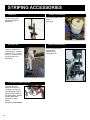
1
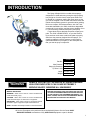
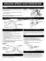
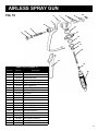
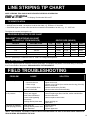
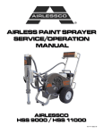
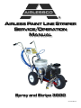
®
AIRLESS PAINT LINE STRIPER
SERVICE/OPERATION
MANUAL
Spray and Stripe 3000
001-703 DEC 08
TABLE OF CONTENTS
SECTION
Introduction...................................................... 1
Safety Warnings .............................................. 2
Setting Up........................................................ 5
Flushing ........................................................... 5
How to Flush ................................................... 6
Starting Up ...................................................... 7
Pressure Relief Procedure .............................. 8
Daily Maintenence ........................................... 8
Line Striping Operation.................................... 9
Airless Spray Gun Operation......................... 10
Airless Spray gun Assembly ...........................11
Airless Spray Gun Troubleshooting ............... 12
Rev Tips ........................................................ 13
Field Troubleshooting .................................... 13
Servicing Fluid Pump .................................... 14
Servicing Outlet Valve ................................... 15
Servicing Inlet Valve ...................................... 15
Packing Replacement Procedures ................ 16
Inspection/Replacement of Control Valve...... 18
Pressure Control Calibration ......................... 18
Bypass Valve Assembly................................. 19
Gearbox Assembly ........................................ 20
Frame Assembly............................................ 21
Spray Gun Assembly ..................................... 22
Gun Mount Assembly .................................... 22
Suction Assembly .......................................... 23
Striping Accessories ...................................... 24
Notes ............................................................. 25
Airlessco Accessories.................................... 26
Airlessco
5397 N. Commerce Ave, Moorpark, CA 93021
www.airlessco.com • (805) 523-0211
2
FIGURE
1 Filling the Packing Nut/Wet Cup................ 5
2. Spray Tip ................................................... 6
3. Control Valve ............................................. 6
4. Choke, Fuel Throttle .................................. 6
5. Static Discharge ........................................ 6
6. Gun Safety Latch..................................... 10
7. Major Gun Components .......................... 10
8. Spray Tip ................................................. 10
9. Spray Tip Assembly ................................. 10
10. Airless Spray Gun Assembly ....................11
11. Fluid Pump............................................... 14
12. Outlet Valve ............................................. 15
13. Inlet Valve ................................................ 15
14. Packing.................................................... 16
15. Packing Cutaway..................................... 17
16. Bypass Valve Assembly........................... 19
17. Gearbox Assembly .................................. 20
18. Frame Assembly...................................... 21
19. Spray Gun Assembly ............................... 23
20. Gun Mount Assembly .............................. 23
21. Suction Assembly .................................... 23
INTRODUCTION
The Spray & Stripe 3000 is a mobile airless sprayer
designed to be used and strong enough to stripe parking
lots yet light on it’s wide tires to stripe sports fields. Plus
it’s based on a contractor quality paint spray pump so the
gun can be snapped out of its holder and can be used as a
mobile airless painting system for general exterior painting.
Built on a compact, well balanced frame, with “No Tools”
removable handlebars, the 3000 combines a dependable
commercial 4-cycle engine, and the proven durability of our
LP “Slow-Stroking” stainless steel piston paint pump.
Forget about stripers that lack the power to spray pure
paint. The 3000 is H2NO READY!, so you don’t have to
figure out how much water to add to the paint to properly
atomize at the pressure designed into the sprayer. You
simply just adjust the 3000’s pressure control knob for
optimal atomiziation of pure paint, or the water/paint mix
that you want to spray or stripe with.
SS3000
Part No.
305-401
Max Pressure
1500 PSI
Output (At Pressure)
0.62 GPM
Tip Size 1 Gun
0.025 in.
Motor Durotech 4HP
Weight
WARNING
162 lbs
HANDLE THIS UNIT AS YOU WOULD A LOADED FIREARM!
HIGH PRESSURE SPRAY CAN CAUSE EXTREMELY
SERIOUS INJURY. OBSERVE ALL WARNINGS!
MANUAL NOTATIONS
WARNING - Alerts user to avoid or correct conditions that
could cause bodily injury.
CAUTION - Alerts user to avoid or correct conditions that
could cause damage to or destruction of equipment.
BEFORE OPERATING THIS UNIT, READ AND FOLLOW
ALL SAFETY WARNINGS AND INSTRUCTIONS RELATED
TO THE USAGE OF THIS EQUIPMENT ON PAGES 2, 3 & 4.
READ, LEARN, AND FOLLOW THE PRESSURE RELIEF
PROCEDURE ON PAGE 8 OF THIS MANUAL.
IMPORTANT - Alerts users to steps or procedures that are
essential to proper equipment repair and maintenance.
NOTE - Identifies essential procedures or extra information.
All Service Procedures to be performed by an Authorized Airlessco Service Center ONLY.
NO MODIFICATIONS or alterations of any AIRLESSCO Equipment or part is allowed.
1
WARNINGS
MEDICAL ALERT - Airless Spray Wounds
If any fluid appears to penetrate your skin, get EMERGENCY
MEDICAL CARE AT ONCE. DO NOT TREAT AS A SIMPLE
CUT. Tell the doctor exactly what fluid was injected. Have
him read the following "NOTE TO PHYSICIAN".
WARNING
HIGH PRESSURE SPRAY CAN CAUSE EXTREMELY SERIOUS INJURY. OBSERVE ALL
WARNINGS. THIS SPRAYER IS FOR PROFESSIONAL USE ONLY.
INJECTION HAZARD
FLUIDS UNDER HIGH PRESSURE FROM SPRAY OR
LEAKS CAN PENETRATE THE SKIN AND CAUSE
EXTREMELY SERIOUS INJURY, INCLUDING THE
NEED FOR AMPUTATION.
NEVER point the spray gun towards anyone or at any part
of the body.
NEVER put hand or fingers over the spray tip. Do not use
rag or other materials over your fingers. Paint will penetrate
through material and into the hand.
NEVER try to stop or deflect leaks with your hand or body.
ALWAYS have gun tip guard in place when spraying.
ALWAYS lock gun trigger when you stop spraying.
ALWAYS remove tip from the gun to clean it.
NEVER try to "blow back" paint, it’s not an air sprayer.
ALWAYS follow the PRESSURE RELIEF PROCEDURE,
as shown on page 8, before cleaning or removing the spray
tip or servicing any system equipment.
Be sure equipment safety devices are operating properly
before each use.
ALWAYS tighten all fluid connections before each use.
MEDICAL TREATMENT
If any fluid appears to penetrate your skin, get
EMERGENCY CARE AT ONCE.
DO NOT TREAT AS A SIMPLE CUT.
• Go to an emergency room immediately.
• Tell the doctor you suspect an injection injury.
• Tell him what kind of material you were spraying with and
have him read NOTE TO PHYSICIAN above.
GENERAL PRECAUTION
2
NOTE TO PHYSICIAN: Injection in the skin is a traumatic
injury. It is important to treat the injury surgically as soon as
possible. DO NOT DELAY treatment to research toxicity. Toxicity is a concern with some exotic coatings injected directly
into the blood stream. Consultation with a plastic surgeon or
reconstructive hand surgeon may be advisable.
NEVER alter equipment in any manner.
NEVER smoke while in spraying area.
NEVER spray highly flammable materials.
NEVER use around children.
NEVER allow another person to use sprayer unless he is
thoroughly instructed on its' safe use and given this
operators manual to read.
ALWAYS wear a spray mask, gloves and protective eye
wear while spraying.
ALWAYS ensure fire extinquishing equipment is readily
available and properly maintained.
NEVER LEAVE SPRAYER UNATTENDED WITH
PRESSURE IN THE SYSTEM. FOLLOW PRESSURE
RELIEF PROCEDURES ON PAGE 8.
ALWAYS INSPECT SPRAYING AREA
Keep spraying area free from obstructions.
Make sure area has good ventilation to safely remove
vapors. NEVER keep flammable material in spraying area.
NEVER spray in vicinity of open flame or other sources of
ignition. Spraying area must be at least 20 ft. away from
spray unit.
SPRAY GUN SAFETY
ALWAYS set safety lock on the gun in "LOCKED" position
when not in use and before servicing or cleaning.
DO NOT remove or modify any part of gun.
ALWAYS remove spray tip when cleaning.
Flush unit with LOWEST POSSIBLE PRESSURE.
CHECK operation of all gun safety devices before each
use. Be very careful when removing the spray tip or hose
from gun. A plugged line contains fluid under pressure. If
the tip or line is plugged, follow the PRESSURE RELIEF
PROCEDURE as outlined on page 8.TIP GUARD
TIP GUARD
ALWAYS have the tip guard in place on the spray gun
while spraying. The tip guard alerts you to the injection
hazard and helps prevent accidentally placing your fingers
or any part of your body close to the spray tip.
SPRAY TIP SAFETY
USE EXTREME CAUTION when cleaning or changing
spray tips. If the spray tip clogs while spraying, engage the
gun safety latch immediately.
ALWAYS follow the PRESSURE RELIEF PROCEDURE
before removing the spray tip to clean it.
NEVER wipe off build up around the spray tip.
ALWAYS remove tip & tip guard to clean AFTER pump
is turned off and the pressure is relieved by following the
PRESSURE RELIEF PROCEDURE.
WARNINGS CONTINUED ON NEXT PAGE.........
WARNINGS - CONTINUED
ALWAYS INSPECT SPRAYING AREA
Keep clear of moving parts when starting or operating
the sprayer. Do not put your fingers into any openings
to avoid amputation by moving parts or burns on hot
parts.Precaution is the best insurance against an
accident.
When starting the engine, maintain a safe distance
from moving parts of the equipment.
Before adjusting or servicing any mechanical part
of the sprayer, follow the PRESSURE RELIEF
PROCEDURE on page 8, and remove the ignition
cable from the spark plug to prevent accidental
starting of sprayer.
HOSES
Tighten all fluid connections securely before each use. High
pressure fluid can dislodge a loose coupling or allow high
pressure spray to be emitted from the coupling and result in
an injection injury or serious bodily injury.
Use only hose that has a spring guard. The spring guard
helps protect the hose from kinks or other damage which
could result in hose rupture and cause an injection injury.
GROUNDING
Ground the sprayer and other components in the system
to reduce the risk of static sparking, fire or explosion which
can result in serious bodily injury and property damage.
ALWAYS GROUND ALL OF THESE COMPONENTS:
1. Sprayer: Connect a ground wire and clamp (supplied) to
a true earth ground.
2. Fluid Hose: use only grounded hoses.
3. Spray gun or dispensing valve: grounding is obtained
through connection to a properly grounded fluid hose
and pump.
4. Object being sprayed: according to your local code.
5. All solvent pails used when flushing should only be
metal pails which are conductive.
Once each week, check electrical resistance of hose (when
using multiple hose assemblies, check overall resistance of
unpressurized hose must not exceed 29 megohms (max)
for any coupled length or combination of hose lengths. If
hose exceeds these limits, replace it immediately.
Never exceed 500 Ft. (150 m.) overall combined hose
length to assure electrical continuity.
NEVER use a damaged hose, which can result in hose
failure or rupture and cause in injection injury or other
serious bodily injury or bodily damage. Before each use,
check entire hose for cuts, leaks, abrasion or bulging of
cover, or damage or movement of couplings. If any of
these conditions exist, replace the hose immediately.
Never use tape or any device to try to mend the hose as it
cannot contain the high pressure fluid. NEVER ATTEMPT
TO RECOUPLE THE HOSE. High pressure hose is not
recoupleable.
Help prevent damage to the hose by handling and routing
it carefully. Do not move the sprayer by pulling it with the
hose.
LABELING
Keep all labels on the unit clean and readable.
Replacement labels are available from manufacturer.
TOXIC FLUID HAZARD
Hazardous fluid or toxic fumes can cause serious injury or
death if splashed in eyes or on skin, inhaled or swallowed.
Know the hazards of the fluid you are using. Store &
dispose of hazardous fluids according to manufacturer,
local, state & national guidelines.
ALWAYS wear protective eyewear, gloves, clothing
and respirator as recommended by fluid manufacturer.
WARNINGS CONTINUED ON NEXT PAGE.........
3
WARNINGS - CONTINUED
AVOID COMPONENT RUPTURE
This sprayer operates at 3000 psi (205 bar). ALWAYS be
sure that all components and accessories have a maximum
working pressure of at least 3000 psi to avoid rupture
which can result in serious bodily injury including injection
and property damage.
NEVER leave a pressurized sprayer unattended to avoid
accidental operation of it which could result in serious
bodily injury.
ALWAYS follow the PRESSURE RELIEF PROCEDURE
whenever you stop spraying and before adjusting,
removing or repairing any part of the sprayer.
NEVER alter or modify any part of the equipment to avoid
possible component rupture which could result in serious
bodily injury and property damage.
NEVER use weak or damaged or non-conductive paint
hose. Do not allow kinking or crushing of hoses or allow it
to vibrate against rough or sharp or hot surfaces. Before
each use, check hoses for damage and wear and ensure
all fluid connections are secure.
REPLACE any damaged hose. NEVER use tape or any
device to mend the hose.
NEVER attempt to stop any leakage in the line or fittings
with your hand or any part of the body. Turn off the unit
and release pressure by following PRESSURE RELIEF
PROCEDURE.
ALWAYS use approved high pressure fittings and
replacement parts.
ALWAYS ensure fire extinquishing equipment is readily
available and properly maintained.
PREVENT STATIC SPARKED FIRE/ EXPLOSIONS
ALWAYS be sure all equipment and objects being sprayed
are properly grounded. ALWAYS ground sprayer, paint
bucket and object being sprayed. See "grounding" on page
3 for detailed grounding information.
Vapors created when spraying can be ignited by sparks.
To reduce the risk of fire, always locate the sprayer at least
20 feet (6 m.) away from the spray area. DO NOT plug in
or unplug any electrical cords in the spray area, which can
create sparks, when there is any chance of igniting vapors
still in the air. Follow the coating & solvent manufacturers
safety warnings and precautions.
Use only conductive fluid hoses for airless applications. Be
sure gun is grounded through hose connections. Check
ground continuity in hose & equipment. Overall (end to
end) resistance of unpressurized hose must not exceed 29
megohms for any coupled length or combination of hose
length. Use only high pressure airless hoses with static
wire approved for 3000 psi.
FLUSHING
Reduce the risk of injection injury, static sparking or
splashing by following the specific cleaning procedure on
page 6 and 8.
ALWAYS follow the PRESSURE RELIEF PROCEDURE
on page 8.
ALWAYS remove the spray tip before flushing. Hold a
metal part of the gun firmly to the side of a metal pail and
use the lowest possible fluid pressure during flushing.
NEVER use cleaning solvents with flash points below 140
degress F. Some of these are: acetone, benzene, ether,
gasoline, naphtha. Consult your supplier to be sure.
NEVER SMOKE IN THE SPRAYING/CLEANING AREA.
GAS ENGINE PRECAUTIONS
WARNING
Do not use halogenated solvents in this system. The prime
valve, 2 gun manifold and most airless guns have aluminum
parts and may explode. Cleaning agents, coatings, paints or
adhesives may contain halogenated hydrocarbon solvents.
DON"T TAKE CHANCES! Consult your material suppliers to
be sure. Some of the most common of these solvents are:
Carbontetrachloride, Chlorobenzene, Dichloroethane, Dichloroethyl Ether, Ethylbromide, Ethylchloride, Tethrachloethane.
Alternate valves and guns are available if you need to use
these solvents.
Place unit 25 feet away from spraying in ventilated area.
NEVER operate in buildings unless exhaust is piped outside.
NEVER allow hose to lay against engine mufflers or hot parts.
NEVER refill fuel tank while engine is hot or is running.
IMPORTANT: United States Government safety standards
have been adopted under the Occupational Safety & Health
Act. These standards, particularly the General Standards,
Part 1910, & the Construction Standards, part 1926 should
be consulted.
WHEN SPRAYING & CLEANING WITH FLAMMABLE PAINTS OR THINNERS:
1.
2.
3.
4.
5.
4
When spraying with flammable liquids, the unit must be located a minimum of 25 feet away from the spraying area in
a well ventilated area. Ventilation must be sufficient enough to prevent the accumulation of vapors.
To eliminate electrostatic discharge, ground the spray unit, paint bucket and spraying object. Use only high
pressure airless hoses approved for 3000 psi which is conductive.
Remove spray tip before cleaning gun and hose. Make contact of gun with bucket and spray without the tip in a well
ventilated area, into the grounded steel bucket.
Never use high pressure in the cleaning process. USE MINIMUM PRESSURE.
Do not smoke in spraying/cleaning area.
SETTING UP
1. CONNECT THE HOSE AND GUN
a. Remove the plastic cap plug from the outlet and screw a
conductive or grounded 3000 psi spray hose onto
fluid outlet.
b. Connect an airless spray gun to the other end of the
hose, but do not install the spray tip yet!
NOTE: Do not use thread sealer on swivel unions as they
are made to self seal.
NOTE: The 6' whip hose should always be 3/8".
2. FILL THE PACKING NUT/WET CUP
Fill the Packing Nut/Wet Cup 1/3 full with Airlessco Throat
Seal Oil (TSO). FIG 1 BELOW.
FIG. 1
3. CHECK THE ENGINE OIL LEVEL
a. Unscrew the oil fill plug. The dipstick is attached to
the plug.
b. Without threading the plug into place, check to be sure
the oil is up to the top mark on the dipstick.
c. If oil is needed, refer to engine manual.
4. FILL THE FUEL TANK
WARNING: Fuel spilled on a hot surface can cause a fire or
explosion and cause serious bodily injury and property damage. Always shut off the engine and let it cool before filling
the tank, and carefully follow steps a - c below being sure not
to spill any fuel.
a. Close the fuel shutoff valve.
b. Use only clean, fresh, well-known brands of unleaded
regular grade gasoline.
c. Remove the fuel cap and fill tank. Be sure the air vent
in the fill cap is not plugged so fuel can flow to the
carburetor, then replace the cap.
5. FLUSH THE SPRAYER
a. Flush sprayer per instructions below.
FLUSHING
1. NEW SPRAYER
Your unit was factory tested in an anti-freeze solution which
was left in the pump. Before using oil-base paint, flush with
mineral spirits only.
Before using water-base paint flush with mineral spirits,
followed by soapy water, then a clean water flush.
2. CHANGING COLORS
Flush with a compatible solvent such as mineral spirits or
water.
3. CHANGING FROM WATER-BASE TO
OIL-BASE PAINT
Flush with soapy water, then mineral spirits.
4. CHANGING FROM OIL-BASE TO
WATER-BASE PAINT
5. STORAGE
Oil-base paint: Flush with mineral spirits.
Water-base paint: Flush with water, then mineral spirits and
leave the pump, hose and gun filled with mineral spirits.
For longer storage, use mixture of mineral spirits and motor
oil (half & half). Shut off the sprayer, follow PRESSURE
RELIEF PROCEDURE on page 8 to relieve pressure and
make sure prime valve is left open.
6. START UP AFTER STORAGE
Before using water-base paint, flush with soapy water and
then a clean water flush.
When using oil-base paint, flush out the mineral spirits with
the material to be sprayed.
Flush with mineral spirits, followed by soapy water, then a
clean water flush.
5
HOW TO FLUSH
1. Be sure the gun safety latch is engaged and there
is no spray tip in the gun. Refer to Fig. 2. Refer to your
separate instruction manual provided with your gun on its
safety features and how to engage safety latch.
2. Pour enough clean, compatible solvent into a large,
empty metal pail to fill the pump and hoses.
3. Place the suction tube into the pail or place the pail
under the pump.
4. Turn the Control Valve to low/prime position (counter
clockwise). This will allow an easy start Refer to Fig. 3.
5. Turn the engine ON/OFF switch to ON.
6. Move the choke toward the closed position as per Fig.4.
7. Move the throttle lever slightly to the left as per Fig.4.
8. Turn the fuel valve ON as per Fig. 4. Pull the start rope.
Pull the engine over against compression stroke and
then let the rope rewind slowly into the starter. Pull
firmly and rapidly to start the engine. Do NOT drop the
rope. Hold on to the handle while rewinding, or the rope
may rewind improperly and jam the assembly. If the
engine does not start, open the choke a little more. If the
engine floods, open the choke all the way and continue
cranking.
9. After the engine is warm, gradually close the choke, raise
the RPM of engine slightly by moving throttle to the left.
Unit will start to prime. Refer to Fig. 3
10. Point the gun into the metal pail and hold a metal part of
the gun firmly against the pail Refer to fig. 5.
11. Disengage the gun safety latch and squeeze the gun
trigger. At the same time, slowly turn the pressure control
valve knob clockwise just enough to move liquid at low
pressure.
12. Allow the pump to operate until clean solvent comes
from the gun.
13. Release the trigger and engage the gun safety latch.
14. If you are going to start spraying, place the pump or
suction tube into the supply container. Release the
gun safety latch and trigger the gun into another empty,
metal container, holding a metal part of the gun firmly
against the metal pail (Fig. 5), forcing the solvent from
the pump and hose. When paint starts coming from gun,
turn control valve to minimum pressure, and engage the
gun safety latch.
15. If you are going to store the sprayer, remove the suction
tube or pump from the solvent pail force the solvent from
the pump and hose. Engage the gun safety latch and
refer to the "Storage" Procedure on page 5. Step 5.
16. Whenever you shut off the sprayer follow the
PRESSURE RELIEF PROCEDURE warning on page 8.
6
FIG. 2
FIG. 3
REMOVE SPRAY TIP. ENGAGE
GUN SAFETY LATCH.
FIG. 4
CHOKE LEVER
FUEL VALVE
THROTTLE LEVER
FIG. 5
MAINTAIN FIRM
METAL TO METAL
CONTACT BETWEEN GUN AND
CONTAINER
WARNING: To reduce the risk of static sparking, which
can cause fire or explosion, always hold a metal part of
the gun firmly against the metal pail when flushing. This
also reduces splashing. Refer to Fig 6.
STARTING UP
1. LEARN HOW TO OPERATE THE
CONTROL VALVE
The control valve sets the prime
or pressure position as well as the
spraying pressure. When the valve
is fully counter-clockwise the unit is
in the prime position. As the control
valve is turned clockwise, the
unit’s output pressure to the gun is
gradually increased until the control
valve is fully clockwise and the unit
is at it’s maximum output pressure
of 1500 psi. This will fully atomize
any stain or paint without needing to
dilute the material.
FOLLOW “PRESSURE RELIEF PROCEDURES” ON
PAGE 8 WHENEVER YOU:
- are instructed to relieve pressure
- stop spraying
- checking or servicing any of the system equipment.
- install or clean the spray tip.
2. PREPARE THE MATERIAL
a. Prepare the material according to the material
manufacturer's recommendations.
b. Place the suction tube into the material container.
3. STARTING THE SPRAYER
a. Control Valve must be "OPEN" in the priming
position.
b. When you have ensured that the gun safety latch is
engaged, attach tip and safety guard.
c. Turn the engine ON/OFF switch to the "ON"
position. Pull rope vigorously until engine starts.
d. After the pump is primed, turn Control Valve to clockwise
start building pressure. Continue turning the Control
valve to set the desired spray pressure.
e. Disengage the gun safety latch and you are ready to
spray.
c. If more coverage is needed, use a larger tip rather than
increasing the pressure.
d. Check the spray pattern. The tip size and angle
determines the pattern width and flow rate.
WARNING
FOLLOW THE "PRESSURE RELIEF PROCEDURE".
To reduce the risk of injection, never hold your hand, body,
fingers or hand in a rag in front of the spray tip when cleaning
or checking for a cleared tip. Always point the gun toward the
ground or into a waste container when checking to see if the
tip is cleared or when using a self-cleaning tip.
WARNING
When you spray into the paint bucket, always use the
lowest spray pressure and maintain firm metal to metal contact
between gun and container.
WARNING
To stop the unit in an emergency, turn the engine off. Then
relieve the fluid pressure in the pump and hose as instructed
in the PRESSURE RELIEF PROCEDURE.
5. WHEN SHUTTING OFF THE SPRAYER
a. Whenever you stop spraying, even for a short break,
follow the "Pressure Relief Procedure".
b. Clean the tip & gun as recommended in the seperate
Gun Manual supplied with the gun.
c. Flush the sprayer at the end of each work day, if the
material you are spraying is water-based, or if it could
harden in the sprayer overnight. See "Flushing". Use a
compatible solvent to flush, then fill the pump and hoses
with an oil based solvent such as mineral spirits.
d. For long term shutdown or storage, refer to the
"Flushing" section of this manual.
WARNING
Be sure to relieve pressure in the pump after filling with
Airlessco Pump Conditioner.
4. ADJUSTING THE PRESSURE
a. Turn the Control Valve clockwise to increase pressure
and counterclockwise to decrease pressure.
b. Always use the lowest pressure necessary to completely
atomize the material.
NOTE: OPERATING THE SPRAYER AT HIGHER
PRESSURE THAN NEEDED, WASTES MATERIAL,
CAUSES EARLY TIP WEAR, AND SHORTENS
SPRAYER LIFE.
AVOIDING TIP CLOGS
There is an easy way to keep the outside of the tip clean from
material build up:
Every time you stop spraying, for even a minute, lock the gun
and submerge it into a small bucket of thinner suitable for the
material sprayed.
Thinner will dissolve the buildup of paint on the outside of tip,
tip guard and gun much more effectively if the paint doesn't
have time to dry out completely.
7
PRESSURE RELIEF PROCEDURE
! IMPORTANT!
TO AVOID POSSIBLE SERIOUS BODY INJURY, ALWAYS FOLLOW THIS PROCEDURE WHENEVER THE
SPRAYER IS SHUT OFF, WHEN CHECKING IT, WHEN INSTALLING, CHANGING OR CLEANING TIPS,
WHENEVER YOU STOP SPRAYING, OR WHEN YOU ARE INSTRUCTED TO RELIEVE THE PRESSURE.
1. Engage the gun safety latch. Refer to the separate
instruction manual provided with your gun on its safety
features and how to engage safety latch.
2. Turn the unit off.
4. Re-engage gun safety latch.
5. Turn Control Valve (Prime/Pressure Relief Valve) as
shown open (priming) to relieve fluid pressure.
3. Disengage the gun safety latch and trigger the gun to
relieve residual fluid pressure.
HOLD METAL PART OF THE GUN IN CONTACT WITH
GROUNDED METAL PAIL. USE MINIMUM PRESSURE !
DAILY MAINTENANCE
1. Always stop the pump at the bottom of its stroke when
you take a break or at the end of the day. This helps
keep material from drying on the rod, damaging
the packings.
2. Keep the displacement pump packing nut/wet cup 1/3
full of Airlessco Throat Seal Oil at all times. The TSO
helps protect the packings and rod.
3. Lubricate Connecting Rod Pin every 3 months.
4. Inspect the packing nut daily. Your paint pump has
Airlessco's patented "Triple Life Packing System".
Packing life will be extended a minimum of 3 times if the
proper packing tightening procedure is followed!
8
PACKING TIGHTENING PROCEDURE:
Inspect the packing nut daily!If seepage of paint into the
packing nut and/ or movement of the piston upward is
found (while not spraying), the packing nut should be
tightened enough to stop leakage only, but not any tighter.
OVERTIGHTENING WILL DAMAGE THE PACKINGS
and reduce the packing life to the life of other piston
pumps.
LINE STRIPING OPERATION
1. CHOOSE THE GUN ARM POSITION
There is a hole in each corner of the striper frame, in which
the gun arm can be mounted. In a standard set up, the gun
arm would be mounted in the right hand near the single
wheel. This allows for an easier visual check for straight
line striping and for basic arc striping.
2. SETTING UP THE GUN
a. Ensure that a striping tip is in the gun.
b. Pick a tip size for the desired line width.
EXAMPLE: a 317ST tip for a four inch line.
c. Place gun into the gun holder, so that the top of the
taper on the gun handle is flush with the edge of the
gun holder.
d. Set gun height for the desired line width. Adjust height
by loosening the small black handle on the gun holder
assembly and slide the gun arm to the correct height.
Now tighten the handle. This will require some
experimentation to find the correct height. It is suggested
that tape, or some other method is used to mark the
height of commonly used settings.
e. Attach the swivel heads to the gun if painting curbs
or wide stripes.
f. Angle the gun slightly forward. This allows the spray
pressure from the guns to help blow dirt and debris out of
the path of the new stripes.
3. CABLE TENSION ADJUSTMENT
Once the handle and gun arm assembly is set up to the
preferred position, pressurize the unit and trigger the gun to
ensure that it activates and releases correctly. If not, adjust
the cable tension as follows:
a. Locate the adjustment knobs on the base of the gun
trigger, where the cable connects to the gun trigger
assembly.
b. Loose the locking nut and move the adjusting screw until
the slack has been removed from the cable.
c. Tighten locking nut and retest gun trigger for proper
function.
NOTE: THERE IS AN ADDITIONAL CABLE
ADJUSTMENT WHERE THE CABLE ATTACHES TO
THE GUN HOLDER ASSEMBLY. USE ONLY IF THE
GUN TRIGGER ADJUSTMENT IS INSUFFICIENT.
4. MISCELLANEOUS OPPERATIONS
a. CURBS: Adjust gun to desired height and turn swivel
head towards curb.
b. WIDE STRIPES: Install wider fan striping tips and raise
the gun height to achieve the desired width line.
c. STENCILS: Install standard spray tip on the gun.
Remove this gun from the gun holder and spray out the
stencils. A second gun and hose can be attatched and
bolted with a ball valve for stencils.
d. STANDARD PAINTING: Same as stencils, but use
additional paint hose as required.
9
AIRLESS SPRAY GUN OPERATION
SPRAY
Attach spray gun to airless unit and tighten fittings securely.
Set the gun safety latch. (Also may be called gun safety
lock, or trigger lock)
FIG. 6
GUN SAFETY LATCH
IN LOCKED POSITION
GUN SAFETY
LATCH
* The gun safety latch should always be set when the gun
is not being triggered.
Read all warnings and safety precautions supplied with the
spray gun and in product manual.
RELEASED
MAJOR COMPONENTS OF SPRAY GUN AND REVERSIBLE SPRAY TIP
FIG. 7
GUN SAFETY
LATCH OR LOCK
FIG. 8
REV-TIP™
O-RING GASKET
REV-GUARD™
REVERSIBLE
SPRAY TIP
TIP GUARD
HANDLE
(FILTER INSIDE)
METAL SEAT
TRIGGER GUARD
SPRAY TIP ASSEMBLY
CLEANING FILTER IN GUN HANDLE
1. Be sure pressure relief procedure is followed before
assembling tip and housing to the gun.
2. Lock gun safety latch.
3. Insert REV-TIP™ cylinder into the REV-GUARD™
(guard housing assembly).
4. Guide metal seat into REV-GUARD™ (guard housing
assembly) through retaining nut & turn until it seats
against the cylinder.
5. Insert O-Ring gasket on metal seat so it fits in the
grooves.
6. Finger tighten REV-GUARD™ retaining nut onto the gun.
7. Turn guard in the desired position.
8. Completely tighten the retaining nut.
FIG. 9
RETAINING NUT
O-RING GASKET
Part # 561-026
To clean the filter, use a brush dipped in an appropriate
solvent. Change or clean filters at least once a day. Some
types of latex may require a filter change after four hours of
operation.
TO REMOVE CLOGS FROM SPRAY TIP
1. Lock gun safety latch.
2. Turn REV-TIP™ handle 180 degrees.
3. Disengage trigger lock & trigger gun into pail.
4. If the REV-TIP™ handle appears locked (resists
turning), loosen the retaining nut. The handle will now
turn easily.
5. Engage gun safety latch & return handle to the
spray position.
RETAINING NUT
REVERSE TO
UNPLUG
REV-GUARD™
GUARD HOUSING ASSEMBLY
G Thread 7/8" 561-002
F Thread 11/16" 561-001
REV-TIP™ CYLINDER
Part # 561-XXX
Spray Position Shown
METAL SEAT
Part # 561-029
CLEANING SPRAY GUN
Immediately after the work is finished, flush the gun out
with a solvent. Brush pins with solvent and oil them lightly
so they will not collect dried paint.
10
CLOGGED FLAT TIP
Should the spray tip become clogged, relieve pressure
from hose by following the "Pressure Relief Procedure."
Secure gun with the safety latch, take off guard, take out
the tip, soak in appropriate solvent & clean with a brush.
(Do not use a needle or sharp pointed instrument to clean
the tip. The tungsten carbide is brittle and can chip.)
AIRLESS SPRAY GUN
FIG. 10
6
7
8
10*
9
5
4
11
1*
2*
3*
12
13
14
15
16
19
17
PARTS LIST FIGURE 10
Item No.
Part No.
1
120-530*
Gun Seat Assembly
2
120-535*
Gasket-Seat
3
120-520*
Needle Assembly
4
120-529
Gun Seat Adapter
5
120-562
Trigger Guard
6
120-539
Pivot Trigger Pin
7
120-509
Gun Head
8
120-540
Actuator Pin (2)
9
120-536
Gun Plate
10
120-038*
Nut
11
120-056
Plastic Washer
12
120-538
Gun Trigger Lock
13
120-055
Wave Washer
14
120-049
Retaining Ring
15
120-082
Handle Seal
16
Description
18
120-090CX Gun Filter-Coarse
120-090FX Gun Filter-Fine
17
120-088
Spring
18
120-099
Gun Handle Assembly
19
120-506
Gun Trigger
*
120-534
Gun Repair Kit
11
AIRLESS SPRAY TROUBLESHOOTING
DEFECTS
CAUSE
CORRECTION
Coarse spray
Low pressure
Increase the pressure
Excessive fogging
(overspray)
High pressure
Material too thin
Reduce the pressure to satisfactory pattern distrabution
Use less thinner
Patten too wide
Spray angle too large
Use smaller spray angle tip
Pattern too narrow
Spray angle too small
use larger spray angle tip (if coverage is OK, try tip in same
nozzle group)
Too much material
Nozzle too large
Material too thin
Pressure too high
Use smaller nozzle
Nozzle too small
Use next larger nozzle
Material too thick
Too little material
Reduce pressure
Thin distribution in center Worn tip
of pattern “horns”
Wrong tip
Change to new tip
Use nozzle with narrow spray angle
Thick skin on work
Material too viscous
Application too heavy
Thin cautiously
Reduce pressure and/or use tip in next smaller nozzle group
Coating fails to close &
smooth over
Material too viscous
Thin cautiously
Spray pattern irregular,
deflected
Orifice clogged
Tip damaged
Clean carefully
Replace with new tip
Craters or pock marks,
bubbles on work
Solvent balance
Use 1 to 3% “short solvents remainder “long” solvents
(this is most likely to happen with material of low viscosity,
lacquers, etc.)
Clogged screens
Extraneous material in paint
Course pigments
Poorly milled pigments
(paint pigments glocculate)
Clean screen
Use coarse screen if orifice size allows.
Use courser screen, larger orifice tips. Obtain ball milled
paint. If thinner has been added, test to see if a cover
screen. Incompatible drop placed on top of paint mixes or
flattens out on the paint mixture & thinners on the surface. If
not, try different thinner in fresh batch of paint.
TEST THE PATTERN
GOOD, FULL
12
SPOTTY PATTERN, INCREASE PRESSURE
LINE STRIPING TIP CHART
NOTE: STRIPING TIPS SHOULD NOT BE USED FOR REGULAR SPRAYING.
REV-TIP™ for Striping, Part Number 562-xxxST
TIP IDENTIFICATION
• 1st 3-digits identifies it as a REV-TIP™ for airless line striping (Part Number 562-xxxST).
• 4th digit is the fan width - the number is half the fan width, e.g., 2means a 4" line width.
• 5th and 6th digits are for the orifice size and is measured in thousandths of an inch, e.g., 17 = 0.017 inch.
The higher the number, the larger the tip.
REVERSIBLE STRIPING TIP SIZE CHART
REV-TIPTM FOR STRIPING 562-XXXST
FAN WIDTH (6” FROM SURFACE)
INCHES
MILLIMETERS
1-2
25-51
2-4
.013
.021
115ST
117ST
51-102
215ST
217ST
219ST
221ST
4-6
102-152
315ST
317ST
319ST
321ST
6-8
152-203
415ST
417ST
419ST
421ST
Oil Base
Latex
Latex
Latex
Striping paint
113ST
ORIFICE SIZE (INCHES)
.015
.017
.019
Oil Base
REV-TIP™ protected By U.S. Patent No. 6,264,115. Other U.S. & foreign patents applied for.
TIP REPLACEMENT
During use, high pressure will cause the orifice to grow larger. This destroys the pattern or will leave tailing or two heavy
lines on the outside of the pattern. REPLACE SPRAY TIP FREQUENTLY!
FIELD TROUBLESHOOTING
PROBLEM
Unit doesn’t prime
CAUSE
Airleak due to:
•Loose suction nut
• Worn o-rings
•Hole in sucktion hose
Stuck or fouled balls
Unit primes but has poor
or no pressure
Unit does not maintain
good spraying pressure
Pressure set too low
Filter(s) are clogged
Outlet valve fouled/worn
Control valve bypassing
excessively*
Packings and/or piston worn
SOLUTION
• tighten suction nut
• replace o-ring (106-011) on suction seat & o-ring (106-020)
below suction seat
• replace suction hose (331-290)
• service outlet valve suction assembly
• turn up pressure
• clean or replace gun filter, inlet filter, and/or manifold filter
• service outlet valve
• clean or replace control valve
• tighten packing nut
• repack unit
Blown spray tip
• replace spray tip
Packings and/or pistons worn • repack unit
Upper seat worn
• replace upper seat
*NOTE: THE CONTROL VALVE WILL ALWAYS BE BYPASSING WHEN THE UNIT IS BUILDING MORE PRESSURE
THAN IS BEING RELEASED BY THE GUN.
13
SERVICING THE FLUID PUMP
FLUID PUMP REINSTALL
FLUID PUMP DISCONNECT
REFER TO FIGURE 11
1. Follow the Pressure Relief Procedure on page 8.
2. Flush the material you are spraying out of the
machine.
3. Remove the connecting rod shield.
4. Move the piston rod to its lowest position by
cycling pump slowly.
5. Turn off the motor.
6. Disconnect fluid hose from fluid pump.
7. Remove the retaining ring from the connecting rod
and slide the sleeve down revealing the connecting
rod pin.
8. Remove the suction tube assembly from the fluid
pump by unscrewing the suction nut with the packing
adjustment tool (189-211).
9. Using a 1/2” wrench unscrew the two bolts from
the cover assembly. The fluid pump will be hanging
loosely at this point.
10.Remove the connecting rod pin out of the
connecting rod, allowing the removal of the fluid
pump from the machine.
FIG. 11
12
REFER TO FIGURES 11 & 13
1. Loosen the packing nut and ensure that the piston rod
is in its upper position in the fluid pump body. Slip the
sleeve & the retaining ring over the piston rod.
2. Push the piston rod up into the connecting rod & align
the holes. Insert the connecting rod pin through the
connecting rod & piston. Slip the sleeve up over the
connecting rod pin and insert the retaining ring into the
groove on the connecting rod.
3. Push the two bolts through the tube spacers & screw
them into the cover assembly. Using a 1/2” wrench,
tighten the two bolts evenly (alternating between them)
until you reach 20 ft-lbs.
4. Reassemble lower suction valve assembly by placing
the suction seat, O-ring, suction ball & suction ball guide
in the suction nut & screw onto fluid pump body.
5. Reconnect fliud hose to fluid pump.
6. Start the machine and operate slowly to check the piston
rod for binding. Adjust the two bolts, holding the fluid
pump body to the cover assembly, if necessary. This will
eliminate any binding.
7. Tighten packing nut clockwise until resistance is felt
against the Belleville Springs, go 3/4 of a turn more. Put
five drops of Airlessco Throat Seal Oil in the packing nut.
8. Run the machine at full pressure for several minutes.
Release the pressure by following the Pressure Relief
Procedure & readjust the packing nut per step 7 above.
9. Install the connecting rod shield so that the
small hole is in the upper right hand corner.
11
1
10
2
9
3
8
4
7
5
6
14
PARTS LIST FIGURE 11
Item No.
Part No.
Description
1
119-028
Connecting Rod Pin
2
331-117
Sleeve
3
331-062
Retaining Ring
4
115-019
Hose Connector
5
331-034
Suction Nut
6
100-318
Bolts
7
331-209
Fluid Pump
8
331-093
Piston Rod
9
331-074
Tube Spacers
10
331-111
Connection Rod Shield
11
331-038
Connecting Rod
12
331-537
Cover Assembly
SERVICING THE OUTLET VALVE
DISASSEMBLY OF THE OUTLET VALVE
FIG. 12
1. Disconnect the Fluid Pump following instructions on
page 14.
2. Place piston holder in a vise. Slide piston into the holder
& lock in place with a 3/8” dowel.
3. Use a 1/4” allen wrench to unscrew the outlet seat
retainer from the piston.
4. Remove the outlet seat, O-ring and outlet ball.
5. Inspect outlet ball & seat for wear. Replace as
necessary. Ensure seat is right side up.
6. While piston is still locked in the holder, install parts back
into the piston in the following order:
1
2
3
BALL, OUTLET SEAT AND O-RING
1
Before reinstalling the outlet seat support, apply two
drops of Loctite No. 242 (blue) on the threads & torque to
20 ft-lbs.
4
NOTE: Airlessco LP pump tool kit 188-197 is required
for this task. Kit includes: Tightening Bar (189-211),
Packing Removal Tool (331-465), Piston Holder (331195), 3/8” dowel (331-196).
6
5
7
SERVICING THE INLET ASSEMBLY
1. Un-thread and remove suction nut from the fluid pump
body.
2. Remove suction seat, O-ring, suction ball and suction
retainer.
3. Clean all parts and inspect them for wear or damage,
replacing parts as needed.
4. Clean inside of the fluid pump body.
5. Reassemble lower suction valve assembly by placing the
suction seat, O-ring, suction ball & suction ball guide in
the suction nut & screw onto fluid pump body.
FIG. 13
8
9
10
PARTS LIST FIGURE 12 & 13
Item No.
Part No.
Description
1
331-708
Piston
2
331-195
Piston Holder
3
331-196
Dowel Pin
4
331-027
Outlet Ball
5
331-100
O-Ring
6
331-026
Outlet Seat
7
331-314
Outlet Seat Retainer
8
331-011
Fluid Pump Body
9
331-029
Suction Ball Guide
10
331-030
Suction Ball
11
106-011
O-Ring
12
331-409
Suction Seat
13
331-034
Suction Nut
11
12
13
15
PACKING REPLACEMENT PROCEDURES
DISASSEMBLY OF THE FLUID PUMP
REFER TO FIGURE 14 & 15
1. Disconnect the Fluid Pump as instructed on page 14.
2. Unscrew & remove the packing nut.
3. Push the piston rod down through the packings & out of
the pump.
4. Now push the packing removal tool up throughthe pump
& remove from the top bringing packings, spacer &
springs along with it, leaving fluid body empty.
*MAKE SURE ALL OLD PACKINGS & GLANDS HAVE
BEEN REMOVED FROM FLUID PUMP.
5. Clean inside of fluid body.
6. Disassemble all parts & clean for reassembly. Discard
any old packings.
7. Lubricate leather packing in lightweight oil for 10 minutes
prior to reassembly.
REASSEMBLY
REFER TO FIGURE 14
1. Take lower male gland & place it down on the
flat side.
2. Take three of the lower polyethylene packings & two of
the leather packings & place onto the male gland inthe
following order with the inverted side down
POLYETHYLENE, LEATHER, POLYETHYLENE,
LEATHER, POLYETHYLENE.
3. Take the female adaptor, which is inverted on both sides
, & place it on top of your assembled lower packings.
4. Follow step 2 with your packings inverted side up.
5. Take the second lower male gland and place it on top
of your assembled packings with the rounded side
down.
6. Take assembled glands & packings (13 pieces) & slide
onto the lower half of the piston.
7. Take the spacer & slide over the top of the piston (it
doesn’t matter which direction it sits, falling onto lower
packings.
8. Take three Belleville Springs & slide over the top of the
piston in the following order:
• First spring, curve facing down
• Second spring, curve facing up
• Third spring, curve facing down
9. Take the upper male gland & place it rounded
side up.
10. Take three upper polyethylene packings & two leather
packings & assemble with inverted side down,
on
to the male gland in the following order: polyethylene,
leather, polyethylene, leather, polyethylene.
11. Take upper female gland & place on top of assembled
upper packings with the inverted side down.
12. Take assembled upper glands & packings (7 pieces) &
slide on over the top of the piston, making sure inverted
sides are down.
16
13. Take the packing holder & replace the white O-ring &
the black O-ring with new ones from the packing kit.
14. Slide the packing holder over the top of the upper
packings so they fit inside.
15. Lubricate inside of the fluid pump body & the outside of
the packings with a light weight oil.
16. Slide assembly into fluid pump body.
TO KEEP PACKINGS SECURED IN CORRECT
POSITION, HOLD THE PUMP BODY UPSIDE DOWN
& PUSH THE COMPLETED ASSEMBLY UPWARDS
INTO THE PUMP BODY. ONCE PLACED INSIDE, TILT
PUMP BODY BACK UP TO KEEP ALL PIECES IN.
17. Tighten packing nut onto the top of the fluid pump
body & tighten until you feel slight resistance against the
Belleville Springs. Using the Packing Adjustment Tool,
tighten another 3/4 of a turn.
!8. Reinstall Fluid Pump as instructed on page 14.
FIG. 14
PARTS LIST ON FOLLOWING PAGE
1
21
20
2
19
18
22
23
3
2
17
16
15
14
13
11
12
10
1
4
5
6
7
8
9
PACKING REPLACEMENT PROCEDURES
FIG. 15
20
14
19*
18*
21
25*
24*
4
22*
17*
16*
1*
15*
13*
11
2*
12*
3*
5
23*
1*
6*
7*
PARTS LIST FIGURE 14 & 15
Item No.
Part No.
1
331-014*
Male Gland
Description
2
331-016*
Packing Polyethylene
3
331-308*
Female Adaptor
4
331-011
Fluid Pump Body
5
331-029
6
7
PARTS LIST FIGURE 14 & 15 CONT
Item No.
Part No.
Description
14
331-708
Piston
15
331-018*
Spacer
16
331-025*
Belleville Springs
17
331-022*
Male Gland
Suction Ball Guide
18
331-023*
Packing Polyethylene
331-030*
Suction Ball
19
331-021*
Female Gland
106-011*
O-Ring
20
331-019
Packing Holder
8
331-409
Suction Seat
21
331-037
Packing Nut
9
331-034
Suction Nut
22
331-307*
Packing Leather
10
331-314
Outlet Seat Retainer
23
331-306*
Packnig Leather
11
331-026
Outlet Seat
24
106-009*
White O-Ring
12
331-100*
O-Ring
25
106-010*
Black O-Ring
13
331-027*
Outlet Ball
*
331-210
Packing Kit
17
INSPECTION & REPLACEMENT OF CONTROL VALVE, BALL & SEAT
1. Use a wrench to unscrew control valve with Stat O-Seal.
2. Make sure that the control valve knob turns freely and
that its stem is not worn unevenly, mushroomed or
otherwise damaged.
3. Remove TC guide, verify that it is unbroken, clean and
notch side is up.
4. Remove control ball. Inspect for any cuts, scratches,
chips, rust or other damage.
5. Use a 7/16” allen wrench to unscrew the control seat
from the valve body. Clean seat and inspect bevel
edge for damage. Also ensure that the gasket on the
underside of the seat is intact.
6. If no obvious damage to the control ball and seat,
place ball into seat and fill with water. If water leaks out
between ball and seat, they must be replaced.
7. Replace control valve, ball, seat and/or TC guide as
necessary.
8. Clean and inspect valve body opening, where the
control seat was installed.
9. Grease valve body opening with multipurpose grease.
10. Screw control seat into valve body and torque to
85 ft-lbs.
11. Place TC guide into control seat with notched side up.
12. Drop control ball into TC guide.
13. Screw control valve with ring seal into pump head.
Torque to 15 ft-lbs.
14. If a new control valve, ball or seat is installed, complete
the Pressure Calibration Procedure.
A REPAIR KIT WITH THE CONTROL BALL AND SEAT
IS AVAILABLE AS KIT-3-3100.
PRESSURE CONTROL CALIBRATION
DO NOT USE THIS PROCEDURE WITHOUT A TEST GAUGE!
1. Install a gun, flexible airless hose and Airlessco part # 111-045 glycerin filled test gauge onto unit.
2. Prime unit.
3. Turn the control valve knob fully clockwise (maximum pressure setting).
4. Read the gauge, it should be approximently 1500 PSI.
5. If maximum pressure is incorrect, remove the orange plastic cap from the control valve knob. Insert a 3/16” allen
wrench into the control valve knob set screw, turn clockwise to increase pressure and counter-clockwise to decrease
pressure. Replace orange plastic cap.
6. NEVER set the maximum pressure above 1500 PSI.
NOTE: NEW CONTROL VALVE REQUIRES A BREAK-IN PERIOD. RUN THE UNIT UNDER PRESSURE FOR
APPROXIMATLY 15 MINUTES OR UNTIL THE MAXIMUM PRESSURE IS STEADY.
18
BYPASS VALVE ASSEMBLY (305-264)
FIG. 16
1
2
7
3
4*
5*
6
7
8
TO PUMP
9
PARTS LIST FIGURE 16
Description
PARTS LIST FIGURE 16 CONT
Item No.
Part No.
Item No.
Part No.
Description
1
115-058
Control Valve
6
305-194
PR Regulator Housing
2
115-028
Stat-O-Seal
7
100-040
Whip Hose (2)
3
115-031
Guide T.C.
8
188-377
Return Tube
4
*115-017
Ball
9
305-293
Deflector
5
*115-016
Control Valve Seat Assy
*
KIT-3-3100 Repair Kit
19
GEARBOX (305-378)
FIG. 17
13
11
6
3
4
7
8
9
12
2
14
15
16
1
10 7
5
21
1
2
16
26
25
24
20
19
18
23 22
27
28
38
29
37
30
31
36
35
34
33
32
PARTS LIST FIGURE 17 CONT
PARTS LIST FIGURE 17
20
Item No.
Part No.
1
100-380
2
100-381
3
Description
Item No.
Part No.
Shoulder Screw (2)
21
305-284
Spider Gear
Screw (2)
22
106-031
J-Clip
331-537
Cover
23
100-398
Retaining Ring
4
331-046
Ball Bearing
24
136-217
Nut (2)
5
331-038
Crosshead Assy
25
188-041
Screw(2)
6
331-407
Crank Assy
26
117-008
Bearing
7
113-093
Retaining Ring
27
119-028
Pin
8
112-068
Ball Bearing
28
331-117
Sleeve
9
305-199
Pinion Shaft
29
331-062
Retaining Spring
10
106-019
O-Ring
30
100-028
1/4” Plug
11
305-047
Ball Bearing
31
331-209
Fluid Pump
12
305-287
End Bell
32
115-019
Hose Connector
13
305-342
Mounting Box Bracket
33
331-074
Spacer (2)
14
100-374
Screw (4)
34
331-061
Sleeve Bearing
15
305-281
Coupling Hub (2)
35
100-318
Screw (2)
16
112-029
Key (2)
36
331-197
Screw (2)
17
175-032
Motor Duro 4HP
37
331-103
Washer (2)
38
331-111
Cover Guard
*
331-132
Grease (1 lb)
18
100-309
Set Screw (4)
19
113-023
Washer (4)
20
100-315
Nut (4)
Description
17
FRAME ASSEMBLY (305-213)
1
FIG. 18
2*
26
3
15 24
25
4
5, 6, 7
17
8
23
16
8
15
9, 10, 11
12
13
14
20, 21, 22
11
19 15 18
17
16
15
PARTS LIST FIGURE 18
Item No.
Part No.
Description
* NOT INCLUDED IN FRAME ASSEMBLY
PARTS LIST FIGURE 18 CONT
Item No.
Part No.
Description
1
305-058
Rubber Grip (2)
15
100-344
Washer (12)
2*
101-349
Label - SS3000
16
113-023
Lock Washer (6)
3
139-053
Handle
17
113-022
Nut (6)
4
119-026
Screw (3)
18
301-536
Shock Mount (4)
5
100-320
Wing Screw (2)
19
301-547
Screw (4)
6
305-051M
Clamp (2)
20
113-032
Axle
7
305-108
Plate (2)
21
112-059
Spacer
8
301-166
Wheel (3)
22
143-028
Washer (2)
9
188-367
Axle
23
305-343
Mounting Plate
10
113-030
Spacer (2)
24
169-050
Screw (2)
11
143-029
Set Collar (4)
25
305-353
Striper Frame
12
305-262
Bucket Base
26*
305-533
Bucket Lid
13
136-133
Key Ring
-
116-103
Spring Clip (4) (not shown)
14
136-131
Chain Sash
21
SPRAY GUN ASSEMBLY (305-280)
FIG. 19
7
1
2
PARTS LIST FIGURE 19
Item No.
6
5
4
3
Part No.
Description
1
120-554
2
562-317ST
008 Gun
3
561-025
Rev-Tip Male Seal
4
561-026
Rev- Tip Seal
5
100-011
Airless 1/4” x 50’ Hose
6
116-105
Spring Clip
7
305-370
Gun Mount Assy
8
560-517
Painting Tip (not installed)
Striping Tip
GUN MOUNT ASSEMBLY (305-370)
FIG. 20
PARTS LIST FIGURE 20
4
5
4
17
5
6
4
1
2
3
18
13
14
12
11
11
16
22
15
19
10
7
8
9
Item No.
Part No.
Description
1
305-089
Cable Sleeve
2
305-141
Cable Adjustor
3
136-217
Nut
4
331-103
Washer (3)
5
305-273
Spacer (2)
6
119-049R
7
116-100
Compression Spring
8
305-079
Wire Swivel Assy
9
140-045
Nut
10
305-161
Spacer
11
305-159
Sleeve Bearing (2)
12
100-342
Screw
Screw
13
100-651
Cable Assy
14
143-027
Ball Guide
15
111-036
Spring Clip
16
305-274
Trigger Lever
17
305-272
Gun Mount Tube
18
119-050R
19
119-052
Nut (3)
20
305-142
Lever Assy
Screw (3)
SUCTION ASSEMBLY (331-290)
FIG. 21
1
2
PARTS LIST FIGURE 21
Item No.
Part No.
Description
1
106-020
PTFE O-Ring
2
331-217
Suction Filter
23
STRIPING ACCESSORIES
POINTER
For easy line-up and
striping of long lines.
PART # 136-069
STENCIL KIT
For use on any single gun
striper for stencilling or
spraying paint. Includes a
2nd gun, 50’ of 1⁄4” airless
hose, 18” extension pole
& shut-off ball valve.
PART # 305-399
FLOATING SPRAY GUN KIT
Upgrades any Brite
Striper 3000 striper to
a floating gun mount for
consistent width lines on
bumpy, uneven surfaces
like sports fields. Wheels
provide added wind
protection for spray
pattern.
PART # 305-355. (PATENT PENDING)
24
12GAL CONTAINER
High capacity plastic paint
bucket
PART # 189-006
BEAD DISPENSERS
Gravity type glass bead
dispenser kits.
1 GUN 4” PN 305-174
1 GUN 4-6” PN 305-186
NOTES
25
ACCESSORIES
AIRLESSCO
Quick Flush
STAY CLEAN™
™
Spray protectant for machine
to prevent paint from sticking
to it. Keeps your sprayer
looking new for years!
■ The only clean water flushing system
■ Cuts sprayer clean-up time in half!
■ Connects to standard garden hose
to backflush sprayer through gun
114-030
■ Includes "F" and "G" adapters to
work with all brands of gun
20 oz. can
Case quantity: 12 cans
Part # 170-005
THROAT SEAL OIL
Used in the wet cup of a piston pump
to prevent paint from drying on the piston & causing damage to the upper
packing. Use with all piston pumps.
PAINT HOPPER
For use on small jobs where paint is
kept in smaller than 5 gallon containers.
Threads onto pick-up tube of carry or
LoBoy framed Airlessco sprayers.
331-775
6 Liter Paint Hopper
PUMP CONDITIONER
188-187
188-392
XTEND-A-POLE SYSTEM
Standard Tip Extension
Should be used on piston pumps
between uses to prevent paint from
drying on the piston & causing packing wear.
010-001
010-009
010-019
Display of 48 - 1 oz. bottles
1 quart bottle
1 Gallon bottle
Case quantity: 12 on quarts, 4 on gallons
PAINT STRAINERS
Pre-filter your paint using strainer
bags. One dozen per pack.
100-064
100-065
Used to cover suction filter
5 Gallon strainer
HOSE COVER
4 mil poly protects your
airless hose from paint and
abrasion damage. Comes in 1000'
roll with perforations each 50'.
100-219
100-426
Hose Cover Roll
Case of 6 Rolls
HIGH PRESSURE AIRLESS HOSE
Strong yet flexible, for airless sprayers up to 3300 PSI
Part No:
100-012
100-040
100-204
100-199
Hose Description
3/16” Whip Hose, 4 Ft.
1/4” Whip Hose, 3 Ft.
1/4” Whip Hose, 5 Ft.
3/8” Whip Hose, 6 Ft.
100-011 1/4” Hose, 50 Ft.
100-023 3/8” Hose, 50 Ft.
100-037 1/2” Hose, 50 Ft.
100-010 1/4" Hose Connector
100-009 3/8" Hose Connector
6 oz. Bottle
1 qt. Bottle
Swivel Extension
Bare Pole
STANDARD TIP EXTENSION, “G” Thread
6” Long
12” Long
18” Long
24” Long
032-170
032-171
032-172
032-173
SWIVEL EXTENSION, “G” Thread
36” Long
032-184
BARE POLE
Add Tip Extension or Swivel Extension to
create desired length
032-053
24” Long
032-054
36” Long
SWIVEL “G” THREAD
032-035 7/8" x 14 Swivel
ADAPTERS
90° Pole to Gun Adapter
032-042
Gun Nut “F” Thread 11/16-16
032-010
Gun Nut “G” Thread 7/8-14
032-011
"F to G" Gun adapter to attach
Graco tips to Airlessco guns.
®
032-012