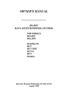
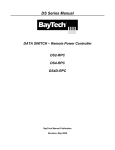
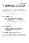
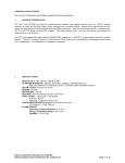
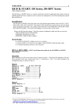
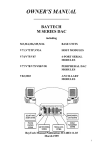
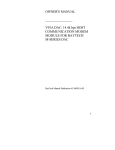
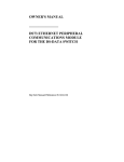
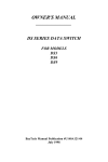
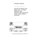
1
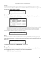
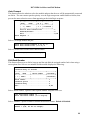
DS Series Manual
DATA SWITCH
DS71-MD4 Host-Modem Module
BayTech Manual Publication
Revision May 2008
Copyright 2007 by Bay Technical Associates, Inc.
BayTech, is a registered trademarks of Bay Technical Associates, Inc.
Windows 2000®, Windows XP® are products and registered trademark of Microsoft Corporation.
Tera Term is a product and registered trademark of Vector, Inc.
DS71-MD4 Serial host and 56k Modem
ABOUT THIS OWNER’S MANUAL .......................................................................................................... 4
Connection Description ......................................................................................................................... 4
EIA-232 SERIAL CONNECTION....................................................................................................... 5
Internal MODEM CONNECTION....................................................................................................... 5
External Modem Connection ............................................................................................................. 5
Installation................................................................................................................................................. 5
Power .................................................................................................................................................... 6
QUICK START: DS71-MD4 Module ......................................................................................................... 6
Serial Setup........................................................................................................................................... 6
Main Menu ............................................................................................................................................ 7
Login Setup ....................................................................................................................................... 8
Local Modem Option ....................................................................................................................... 10
Cabling ................................................................................................................................................... 10
RJ-45 Cables and Adapters ................................................................................................................ 10
Adapters.............................................................................................................................................. 11
Detailed Operation and Configuration .................................................................................................... 13
DS71-MD4 Main Menu........................................................................................................................ 13
Configuration Menu............................................................................................................................. 13
Host Module Configuration .............................................................................................................. 13
Configuration Status .................................................................................................................... 14
Serial Port Configuration.............................................................................................................. 16
Port Device Name........................................................................................................................ 18
Port Select Code.......................................................................................................................... 18
Attention Character ...................................................................................................................... 18
Disconnect Timeguard ................................................................................................................. 19
Connect port ID Echo................................................................................................................... 19
Login Setup.................................................................................................................................. 19
Header...................................................................................................................................... 20
Access Control ......................................................................................................................... 20
Menu ........................................................................................................................................ 20
Manage Users .......................................................................................................................... 20
Auto Connect............................................................................................................................ 22
Dial-Back Number .................................................................................................................... 22
Assign User Ports..................................................................................................................... 23
Local Modem Option.................................................................................................................... 24
Ring to Answer ......................................................................................................................... 24
Connectivity Timeout................................................................................................................ 24
Inactivity Timeout ..................................................................................................................... 24
Unit ID .......................................................................................................................................... 25
I/O modules Reset .............................................................................................................................. 25
Unit Reset ........................................................................................................................................... 25
Troubleshooting: ..................................................................................................................................... 25
Functional Solutions:........................................................................................................................... 25
DS71-MD4 Reset Procedure .............................................................................................................. 27
BayTech Product Warranty..................................................................................................................... 27
Technical Support ............................................................................................................................... 28
Return Authorization Process: ............................................................................................................ 29
3
DS71-MD4 Serial host and 56k Modem
ABOUT THIS OWNER’S MANUAL
This document provides information required for installing and operating your Bay Tech equipment. It
should allow the user to connect to, power up, and access an applications menu where peripheral
equipment can be controlled. We recommend reading this manual carefully, while placing special
emphasis on correct cabling and configuration. If you have any problems with your installation, please
contact BayTech’s Technical Support at 228-563-7334, call toll free from anywhere in the United States
using 1-800-523-2702 or contact us at our Web Site, www.baytech.net.
BayTech manufactures many remote site management products, data switches, data collection
multiplexers, and remote power controllers. If you would like information on any of these products,
please contact BayTech Customer Service at the above numbers or visit our web site.
Conventions used in this manual include:
•
•
•
•
CAUTION: This term is used to denote any condition that could possibly result in physical
harm to personnel or damage to equipment.
IMPORTANT: This term is used to denote conditions that could result in the loss of
communications or to highlight the proper functioning of equipment.
NOTE: This term is used to denote items of interest to the user.
<cr>: Carriage Return or ENTER
The information in this document is subject to change without notice. The statements, configurations,
technical data, and recommendations in this document are believed to be accurate and reliable, but are
presented without express or implied warranty. Users must take full responsibility for their applications
of any products specified in this document. The information in this document is proprietary to Bay
Technical Associates, Inc.
In the interest of improving internal design, operational function, and/or reliability, Bay Technical
Associates, Inc reserves the right to make changes to the products described in this document without
notice.
Bay Technical Associates, Inc does not assume any liability that may occur due to the use or application
of the product(s) or circuit layout(s) described herein.
BayTech units are in accordance with the general requirements of Standard for Information Technology
Equipment (ETL listed, conforms to ANSI/UL STD 60950-1-2003 CERTIFIED CAN/CSA C22.2 NO.
60950-1-03, UL STD 231 8TH EDITION, UL STD 1950 3RD EDITION CERTIFIED CAN/CSA 22.2
NO. 950-95, CE conforms to IEC 60950-1).
We welcome any comments you may have about our products, and we hope that you will continue to
look to BayTech for your data communication needs.
Connection Description
BayTech's DS71-MD4 host communication modem module provides an interface that controls user
access to the DS Series data switch and other DS Series connected modules. The DS71-MD4 is a system
data controller that directs operations between the base unit, system modules and externally connected
devices.
4
DS71-MD4 Serial host and 56k Modem
EIA-232 SERIAL CONNECTION
The DS-Series host communications modules have an RJ-45 port which uses an 8-pin crossed modular
cable to connect to a local EIA-232 device such as a computer terminal or external modem. Most serial
computers do not have RJ-45 connections; therefore an adapter is provided with this unit to convert from
a DE-9 connector to an RJ-45 connector (Bay Tech Part No. 9FRJ45PC-4). An adapter to convert from a
DB-25 connector to an RJ-45 connector is also available from Bay Tech, upon request (Bay Tech Part
No. 25FRJ45PC-4). The 8-pin crossed modular cable is configured to operate with these adapters.
Configure serial communications parameters for the host terminal to match the DS71-MD4 module. The
modules have factory serial communications parameters of 9600 bps, 8 data bits, 1 stop bit, no parity,
XON/XOFF disabled.
Internal MODEM CONNECTION
The DS71-MD4 Host Communications Module has a Flash upgradeable 56 Kbps (V.90bis) modem
which allows two RJ-11 ports connected to standard dial-up telephone lines to be used between the Data
Switch unit and the user's Telco wall jack using a standard RJ-11 straight through cable. These ports are
in parallel and the second port is available for another Telco device using communications software, dial
the modem using the ATDT command.
IMPORTANT: The DS71-MD4 modem option has priority over the EIA-232 serial port. If a serial port
user is in configuration mode or connected to a DS74 I/O port when a modem connection is established,
the serial port user will be “booted” off, allowing the remote user to communicate with the DS unit.
External Modem Connection
Using the 25MRJ45MD-6 adapter (or other applicable adapter) and the RJ08X007 crossed cable,
connect the COM (or serial) port of the modem to the RJ-45 port labeled EIA-232 on the DS71-MD4
module. Using an RJ04X007 (RJ-11) modular cable, connect the port labeled “LINE” on the modem to
the Telco wall jack. The 25MRJ45MD-6 is not shipped with unit but is available upon request at time of
purchase.
Installation
UNPACKING
Compare the unit and serial number of the equipment you received to the packing slip located on the
outside of the box. Inspect equipment carefully for damage that may have occurred in shipment. If there
is damage to the equipment or if materials are missing, contact BayTech technical support at 228-5637334 or call toll free inside the United States at 800-523-2702. At a minimum, you should receive the
following:
1. The DS71-MD4 Module.
2. Manual insert describing the location of the User’s Guide on BayTech’s website at
www.baytech.net.
3. Power Cords that may be attached to the unit (if order requested detachable cords).
4. 1 ea. DE-9 (9 pin) PC com port adapter -- 9FRJ45PC (with Cisco Interface) or 9FRJ45PC-1.
5. 1 ea. RJ-45 Roll over cable -- RJ08X007.
NOTE: Keep the shipping container and packing material in the event future shipment is
required.
5
DS71-MD4 Serial host and 56k Modem
Power
CAUTION: This unit is intended for indoor use only. Do not install near water or expose this unit to
moisture. To prevent heat buildup, do not coil the power cord when in use. Do not use extension cords.
Do not attempt to make any internal changes to the power source. Do not attempt to modify any portion
or component of a DS-Series Data Switch unless specifically directed to; as in Appendix E of this
manual. BayTech must perform any internal changes.
CAUTION: High-voltage surges and spikes can damage this equipment. To protect from such power
surges and spikes, this unit must have a good earth ground. A grounding screw connection is located
near the power switch on the back of the unit.
CAUTION: Before removing or replacing any modules, turn off main power switch located on the DSSeries Base Unit. Communication to the DS-Series Data Switch will be disrupted while power is off.
QUICK START: DS71-MD4 Module
by Bay Technical Associates
For those Administrators who have requested the bare minimum for this type of equipment, follow these
steps exactly. If this is a new unit shipped directly from Baytech, follow the steps. If this is a previously
own unit, perform a factory reset to clear out any users and passwords still in the unit.
Serial/Modem Configuration:
1. Connect the 9FRJ45PC-4 or 9FRJ45PC-1 adapter to your PC.
2. Connect the supplied rollover flat cable RJ08X007 to the adapter and to the EIA232 serial port
on the Baytech DS71-MD4 Module.
3. Use terminal emulation software to access the unit, (i.e. Microsoft Hyper-terminal). Set the PC
serial port configuration to the following: 9600 bps, 8 data bits, 1stop bit and no parity.
4. If you get only a blinking cursor Press ‘Enter’. If still only a blinking cursor, Type 5 semi-colons
(;),The Attention Character will not echo on the screen. There is a one second delay before the
menu is displayed. You should see a menu similar to (Figure 1).
5. Select ‘C’ for the configuration menu.
6. Select the DS71-MD4 module. You should see a menu similar to (Figure 2).
7. Select the number for ‘Login Setup’ option. You should see a menu similar to (Figure 3).
8. Select the number for ‘Manage Users’ option. You should see a menu similar to (Figure 4).
9. NOTE: The ‘admin’ user can not be deleted.
10. Select ‘A’ to add user. Type the name and password at the prompts.
11. Press ‘Enter’ until get to the ‘Login Setup Menu’ (Figure 3).
12. Select option ‘Access Control’ to enable or disable the Modem and Serial Login Prompts.
13. Press ‘Enter’ until get to the ‘Login Setup Menu’ (Figure 3).
14. Select option ‘Assign User Ports’ (Figure 5).
15. Select the user and add the ports.
16. Press ‘Enter’ until you get the Configuration menu (Figure 2).
17. Select ‘Serial Port Configuration’ and set up the modem configuration.
At this point you have setup enough basic configurations to operate this Baytech unit.
Serial Setup
•
Connect the 9FRJ45PC-4 adapter to the user’s computer
6
DS71-MD4 Serial host and 56k Modem
•
•
Connect the Host Module’s EIA-232 port to the adapter via the RJ08X007 rolled flat ribbon
cable.
Default configuration is 9600 bps, 8 data bits, 1 stop bit and no parity.
NOTE: At any time during the session you need to go to another menu, use the Attention
Character = semi-colon (;). Press the attention character key 5 consecutive times to get back to the
main status menu.
NOTE: Depending on the DS-Series model, the menus will vary according to the number of DS74
modules installed in the unit. If this is not an initial set-up and Password has already been enabled,
you are prompted to login. After logging in successfully, invoke the main menu by sending the
attention character five times (;;;;;).
NOTE: Password feature is case sensitive. (Default is user/password is root/baytech)
Main Menu
The following Header and Menu appears or similar:
Figure 1
Data Switch Series - F.1.04.00
Bay Technical Associates
Unit ID: DS71-MD4
Attention Character: ;
Module 1: admin
on Host EIA-232
Device A
(3,1).................1
Device B
(3,2).................2
Device C
(3,3).................3
Device D
(3,4).................4
DS-RPC
(5,1).................5
Configuration .........................C
I/O Modules Reset .....................RM
Unit Reset ............................RU
Exit ..................................X
Logout ................................T
Enter Request :
Select option ‘C’ for the configuration menu. Select the DS71-MD4 module option and the following
menu is displayed:
7
DS71-MD4 Serial host and 56k Modem
Figure 2
Copyright(C) Bay Technical Associates 2006
DS71-MD4 Data Switch Series - V90 Modem Host Module
Revision F.1.01.01
Module 2
Status .........................1
Serial Port Configuration.......2
Port Device Name................3
Port Select Code................4
Attention Character.............5
Disconnect Timeguard............6
Connect port ID Echo ...........7
Login Setup ....................8
Local Modem Option .............9
Unit ID ........................U
Exit ........................X, CR
Enter Request :
Login Setup
This menu allows the user to enable or disable the Header, Access Control, Menu, Manage Users, Auto
Connect, Dial Back Number, and Assign User Ports.
Figure 3
Login Setup:
Header .......................1 Enable/Disable header for each menu
Access Control ...............2 Enable/Disable Network/Serial port user name
and password.
Menu .........................3 Enable menu on startup or 5 attention Char.
Manage Users .................4 Add/Delete users and change passwords.
Auto Connect .................5 Auto connect to module and port on power-up,
Has priority over setup menu, Disables the
menu selection screen on initial login.
Dial Back Number .............6 Have the modem to dial back the user
Assign User Ports ............7 Assign users to specific ports
Exit ......................X,CR Returns to previous menu
Enter Request :
Header
This allows the admin to have enable or disable Header upon connection to the host module.
Access Control
This security feature allows the admin to enable or disable usernames and passwords for both serial and
modem port access.
Menu
This allows the admin to enable or disable the Menu on start up. The default user and password is
“admin/baytech”, all lower case.
8
DS71-MD4 Serial host and 56k Modem
Manage Users
This option allows the administrator to change user passwords or add/delete new users. Up to 19 users
plus an administrator allowed. Usernames are case sensitive and alphanumeric.
Figure 4
User Management Menu:
”admin” .............................. 1
Add New User ..........................A
Delete User ...........................D
Change User ...........................C
To change user password, enter number of user
Enter Request :1
Auto Connect
This feature allows the admin to select the module and port that the user will be automatically connected
on dial-in.
Dial-Back Number
This allows user to dial in, hang up and the unit dials the assigned number back when using a secure
phone line.
Assign User Ports
This option allows the administrator to limit users’ port access.
Figure 5
Assigned User Ports:
+----+----------* +-M3-+-M4-+-M5-+
|User|
Name
\|1234|1234|1234|
+----+------------*----+----+----+
| 2 | johnt
|x234|123x|1xx4|
+----+------------*----+----+----+
Add Port(s)............................1 Adds individual ports
Remove Ports(s)........................2 Removes individual ports
Add All Ports..........................3 Add All
Remove All Ports.......................4 Remove All
Exit ..................................X,CR
Enter Request :1
9
DS71-MD4 Serial host and 56k Modem
Local Modem Option
Figure 5
Local Modem Option:
Rings to Answer ....................1 Auto-answer 1-4, Default 2
Connectivity Timeout ...............2 5-255 minutes, Default 60 minutes
Inactivity Timeout .................3 1-120 minutes, Default 0
Exit ...........................X, CR
Enter Request :
Ring to Answer
This option sets the number of rings before the unit answers.
Connectivity Timeout
This option sets the continuous connectivity time (5 to 255 minutes) before the modem automatically
disconnects.
Inactivity Timeout
This option sets the time the modem will automatically disconnect, if there is no activity equaling the
programmed amount of time (1 to 120 minutes).
Cabling
RJ-45 Cables and Adapters
DS71-MD4 EIA-232 RJ-45 Signal
Pin
1
EIA 232
Signal
DTR
Signal
Direction
Out
Description
2
3
GND
RTS
Out
Handshake, Line Driver Inactive State = High: +12 V when power is
applied. Not used to enable/disable.
4
5
6
7
TX
RX
DSR
GND
Out
In
In
Transmit Data Out
Receive Data In
8
CTS
In
Handshake, Line Driver Inactive State = High: +12V when power is
applied. Used as a handshake line to enable/disable the receiving of
characters.
Signal Ground
Handshake In. –12V when not used.
Signal Ground, when Jumper JP6-2 is connected to JP6-3. In order for the
module to take advantage of “DCD Logon/Logoff” and “Auto Connect
Port”, Jumper JP6-2 is connected to JP6-1 providing DCD In.
Used as a handshake line to enable/disable the receiving of characters.
10
DS71-MD4 Serial host and 56k Modem
Adapters Signals
Listed are the pin specifications for the BayTech cable and adapters and the terminal COM ports:
Signal
DTR
GND
RTS
TXD
RXD
DSR
GND
CTS
DTR
DCD
RI
RS-232
Port (DS)
1
2
3
4
5
6
7
8
RS-232
Port (RPC)
1
2
3
4
5
N/C
7
8
9
COM Port
DE-9 Pin
4
7
3
2
6
5
8
4
1
COM Port
DB-25 Pin
20
1
5
2
3
6
7
4
8
22
Signal
DSR
GND
CTS
RXD
TXD
DTR
GND
RTS
DCD
DTR
Adapters
9FRJ45PC (With Cisco Interface)
9FRJ45PC-1 (Without Cisco Interface)
11
DS71-MD4 Serial host and 56k Modem
RJ08X007
Figures 1 and 2 provide visual representation of an RJ-45 receptacle and plug.
12
DS71-MD4 Serial host and 56k Modem
Detailed Operation and Configuration
DS71-MD4 Main Menu
The menu may vary according to the number of DS74 modules installed in the unit. With a proper
connection to the unit upon power-up or unit reset, the following menu is displayed:
Module 2: admin
on Host EIA-232
Device A
(2,1).........1
Device B
(2,2).........2
Device C
(2,3).........3
Device D
(2,4).........4
DS-RPC
(5,1).........5
Configuration .................C Module setup
I/O Modules Reset ............RM Reset all I/O ports
Unit Reset ...................RU Resets DS-unit. All internal and external
communications are lost
Exit ..........................X Access to additional menu options
Logout ........................T Logout the user
Enter Request :c
NOTE: Only the Admin user will see the Configuration, Unit Reset, and I/O Module Reset
options. All users will see only the ports assigned to them, alone with ‘Exit’ and ‘Logout’.
Configuration Menu
The configuration menu allows the admin user to choose a module to access and edit its configuration.
The following pages define each line of the configuration menu. Changes take effect immediately.
Module Configuration
DS71-MD4
(2)..........1 Host Module
DS74
(3)..........2 I/O EIA232 ports
DS-RPC
(5)..........3 Assign users, outlet name, Enable/Disable
confirmation/status menu, unit id, alarm set
Exit......................X,CR
Enter Request :
Host Module Configuration
Enter the number that corresponds with the Host Module followed by a <cr> and the Host Module
responds without the option description:
13
DS71-MD4 Serial host and 56k Modem
Copyright(C) Bay Technical Associates 2006
DS71-MD4 Data Switch Series - V90 Modem Host Module
Revision F.1.01.01
Module 2
Status .........................1
Serial Port Configuration.......2
Port Device Name................3
Port Select Code................4
Attention Character.............5
Disconnect Timeguard............6
Connect port ID Echo ...........7
Login Setup ....................8
Local Modem Option .............9
Unit ID ........................U
Exit ........................X,CR
Current status of DS71-MD4 module
Change port config, 9600, 8, 1, none
Change the name of the device
Non-Menu, ASCII code to select DS74 port
(;;;;;) get Main Menu
Delay to see if more data after ‘;’ char
Enable echo module & port#, device name
Mange user, Port, Header
MD4 options
Name the module
Return to previous menu
Configuration Status
The Status menu displays the modules installed and the current configuration of the host module. The
following are the factory default settings:
14
DS71-MD4 Serial host and 56k Modem
Installed Modules :2,3,5
Port Select Code ......................$BT
Attention Character ...................;
Disconnect Time Guard .................Disabled
Port ID Echo ..........................Disabled
Unit ID ...............................DS71-MD4
Local
Rings
Modem
Modem
Modem Option:
to Auto-Answer................... 2
Connectivity Timeout.............60 minutes
Inactivity Timeout...............60 minutes
Login Setup:
Header Text ...........................Enabled
Menu Mode .............................Enabled
Auto Connect Module & Port
+----+------------+------+----------+
|User|
Name
| M: P | Auto
|
+----+------------+------+----------+
| 1 | admin
| 1: 1 | Disabled |
+----+------------+------+----------+
Assigned User Ports:
+----+----------* +-M3-+-M4-+-M5-+
|User|
Name
\|1234|1234|1234|
+----+------------*----+----+----+
| 1 | admin
|1234|1234|1234|
+----+------------*----+----+----+
User Dialback Phone number
+----+-----------+-----------------+----------+
|User|
Name
| Phone number
| Dialback |
+----+-----------+-----------------+----------+
| 1 | admin
|
| Disabled |
+----+-----------+-----------------+----------+
Dialback Delay.........................10 seconds
Access Control:
Serial Port access:
1)...Prompt for User Name:
2)...Prompt for Password :
Modem Port access:
3)...Prompt for User Name:
4)...Prompt for Password :
Disabled
Disabled
Disabled
Disabled
Auto Connect Module & Port
+----+------------+------+----------+
|User|
Name
| M: P | Auto
|
+----+------------+------+----------+
| 1 | admin
| 1: 1 | Disabled |
+----+------------+------+----------+
+----+----------------+-------+------+------+------+----+----+----+----+
|Port|
Port
| Baud | Word | Stop |Parity|Xon/ Xoff|LineDrive|
|
|
Name
| Rate | Size | Bits |
|Xmit|Recv|DTR |RTS |
+----+----------------+-------+------+------+------+----+----+----+----+
| 1 |Host EIA-232
| 9600 |
8 |
1 | None | Off| Off|High|High|
| 2 |Host V90 Modem | 115.2k|
8 |
1 | None | Off| Off|High|High|
+----+----------------+-------+------+------+------+----+----+----+----+
15
DS71-MD4 Serial host and 56k Modem
Serial Port Configuration
Handshaking, Baud Rate, Word Size, Stop Bits, and Parity are configured through either the serial or
Ethernet ports using the menus. Xon/Xoff, RTS and DTR Line Drivers can only be configured through
the phone line via a modem. The default settings are 9600bps, 8 data bits, no parity, one stop bit,
Xon/Xoff Off and RTS/DTR High.
IMPORTANT: Changing the Host module serial port configuration could create a
communications lock-out if the terminal computer serial port configuration does not match the
host module.
+----+----------------+-------+------+------+------+----+----+----+----+
|Port|
Port
| Baud | Word | Stop |Parity|Xon/ Xoff|LineDrive|
|
|
Name
| Rate | Size | Bits |
|Xmit|Recv|DTR |RTS |
+----+----------------+-------+------+------+------+----+----+----+----+
| 1 |Host EIA-232
| 9600 |
8 |
1 | None | Off| Off|High|High|
+----+----------------+-------+------+------+------+----+----+----+----+
Exit/Save......1 Set Parity........5
Set Baud Rate..2 Set Xon/Xoff......6
Set Word Size..3 RTS Line Driver...7
Set Stop Bits..4 DTR Line Driver...8
Enter Request :
Baud Rate
Select “Baud Rate” to change the rate the modem transfers Data bites per second, the DS displays the
following: Default is 9600
" 300 "
" 600 "
" 1200 "
" 2400 "
" 4800 "
" 9600 "
"19200 "
"38400 "
"57600 "
"115.2k"
Enter Select :
......1
......2
......3
......4
......5
......6
......7
......8
......9
......A
Word Size
The word size is the measurement of the actual data bits in a transmission. Which setting you choose
depends on what information you are transferring. For example, standard ASCII has values from 0 to
127 (7 bits). Extended ASCII uses 0 to 255 (8 bits). If the data being transferred is simple text (standard
ASCII), sending 7 bits of data per packet is sufficient for communication. A packet refers to a single
byte transfer, including start/stop bits, data bits, and parity.
Select “Word Size” and the DS displays the following: Default is 8
16
DS71-MD4 Serial host and 56k Modem
"
5
"
6
"
7
"
8
Enter Select
"
"
"
"
:
......1
......2
......3
......4
Stop Bits
The Stop Bits are used to signal the end of communication for a single packet. Since the data is clocked
across the lines and each device has its own clock, it is possible for the two devices to become slightly
out of sync. Therefore, the stop bits not only indicate the end of transmission but also give the computers
some room for error in the clock speeds. The more bits that are used for stop bits, the greater the
lenience in synchronizing the different clocks, but the slower the data transmission rate.
Select “Stop Bits” the DS displays the following: Default is 1.
"
1 " ......1
"
2 " ......2
Enter Select :
Parity
Parity is a simple form of error checking used in serial communication. For even and odd parity, the
serial port will set the parity bit (the last bit after the data bits) to a value to ensure that the transmission
has an even or odd number of logic high bits. For example, if the data was 011, then for even parity, the
parity bit would be 0 to keep the number of logic high bits even. If the parity was odd, then the parity bit
would be 1, resulting in 3 logic high bits. This allows the receiving device to know the state of a bit so as
to enable the device to determine if noise is corrupting the data or if the transmitting and receiving
devices' clocks are out of sync.
With no parity selected, it's assumed that there are other forms of checking that will detect any errors in
transmission. No parity also usually means that the parity bit can be used for data, speeding up
transmission. In modem-to-modem communication, the type of parity is coordinated by the sending and
receiving modems before the transmission takes place.
Select “Parity” the DS displays the following: Default is None.
" None " ......1
" Even " ......2
" Odd " ......3
Enter Select :
XON/XOFF
For a simple communication between modems three connected lines are needed: TX, Rx, and Ground.
For the data to be transmitted, both sides have to be clocking the data at the same baud rate. While this
method is sufficient for most applications, it is limited in being able to respond to problems such as the
receiver getting overloaded. This is where serial handshaking can help. XON/XOFF is software data
flow communications protocol for controlling the flow of data between Baytech and other devices.
Baytech units will send an XOFF character when it can't take any more data and when it can once again
take more data, will send an XON character to the transmitter.
Select “Xon/Xoff” the DS displays the following, Default is Off:
17
DS71-MD4 Serial host and 56k Modem
Output Flow Control (Xmit) - Xon/Xoff is ( Off )
Stop/Restart Output Upon Receiving of Xoff/Xon ? (Y/N) :
Input Flow Control (Recv) - Xon/Xoff is ( Off )
Xoff/Xon sent based on Buffer - Full/Empty condition ? (Y/N) :
RTS/DTR Line Driver Inactivity State
RTS (Request to Send)/ DTR (Data Terminal Ready) is normally used in conjunction with an external
modem. With no modem the RTS and DTS default state is High.
Select “RTS Driver State” the DS displays the following:
RTS Line Driver Inactive State is: High
High ? (Y/N, CR for no change):
Select “DTR Driver State” the DS displays the following:
DTR Line Driver Inactive State is: High
High ? (Y/N, CR for no change):
Port Device Name
Select a port and type the new name:
Enter New Port Name (Max. 16 characters):
or press ENTER for no change ................:
Port Select Code
The Port Select Code is an ASCII character string sent by the host terminal to the module to select an
I/O port on a DS74 peripheral module. The Port Select Code’s factory default setting is $BT and is
programmable up to 8 characters as shown.
Port Select Code :$BT
Change It ? (Y/N) :
Attention Character
Pressing the Attention Character 5 consecutive times will access the network main menu. The Default is
a semi-colon (;). Select this option to change the attention character. The DS displays the following:
Attention Character :;
Change It ? (Y/N) :
NOTE: If you change the attention character and forget which letter or symbol you selected, the
attention character will not echo if you are typing the correct character. You can type each
character/symbol on the keyboard to find it, or reset the module to factory default to get the
semi-colon back.
18
DS71-MD4 Serial host and 56k Modem
Disconnect Timeguard
This feature ensures reliable binary data transmission by providing a one-second “Timeguard” after the
DS-Series receives the attention character. If more data is received within the delay period, the DS
treats the character as data, not an attention character; thereby preventing unwanted port disconnection.
The Default setting is Disabled.
Disconnect Time Guard :Disabled
Enable ? (Y/N, CR for no change):
Connect port ID Echo
When a user logs into the DS unit the port is identified in the following example:
BAYTECH
For further information check:
http://www.baytech.net/
DS71MD4
or
02,1
<= Device name Port echo.
<= Module and Port Number echo.
Select option 1, to disable the echo. The Default setting is Disabled.
Select option 2 to echo the module and port number. (i.e. 3,2)
Select option 3 to echo the device name. (Device A)
Disable Port ID Echo ...........1
Use Module, Port Number ........2
Use Port Name ..................3
Login Setup
This menu allows the user to enable or disable the Header, Access Control, Menu, Manage Users, Auto
Connect, Dial Back Number, and Assign User Ports.
Login Setup:
Header .......................1 Enable/Disable header for each menu
Access Control ...............2 Enable/Disable Network/Serial port user name
and password.
Menu .........................3 Enable menu on startup or 5 attention Char.
Manage Users .................4 Add/Delete users and change passwords.
Auto Connect .................5 Auto connect to module and port on power-up,
Has priority over setup menu, Disables the
menu selection screen on initial login.
Dial Back Number .............6 Have the modem to dial back the user
Assign User Ports ............7 Assign users to specific ports
Exit ......................X,CR Returns to previous menu
Enter Request :
19
DS71-MD4 Serial host and 56k Modem
Header
If enabled, the following header appears with the main menu upon initialization of power or after a
modem connection to the host module has been established. If disabled, the header does not appear with
the main menu. Default Header is enabled.
Header Text :Enabled
Enable ? (Y/N, CR for no change):
Access Control
This feature configures the Serial and Modem port access by enabling the module to prompt for user
name and password. Default for both is disabled.
Access Control:
Serial Port access:
1)...Prompt for User Name:
2)...Prompt for Password :
Modem Port access:
3)...Prompt for User Name:
4)...Prompt for Password :
Enter Select :
Disabled
Disabled
Disabled
Disabled
CAUTION: Before you enable the password for either Serial Port or Network access, verify the
admin password is known, or you could create a lockout condition. If the password lockout
condition occurs, you will need to reset the DS71-MD4 host module to the factory defaults.
The host module confirms the option you selected to change.
Enable prompt for network user name? (Y/N)>y
Menu
This allows the admin to enable or disable the Menu on start up. If disabled, the header appears upon
login without the main menu. To invoke the main menu when disabled, enter the attention character five
times (;;;;;).
Menu Mode :Enabled
Enable ? (Y/N, CR for no change):
The default user and password is “admin/baytech”, all lower case.
Manage Users
This option allows the administrator to change user passwords or add/delete new users. Up to 19 users
plus an administrator allowed. Usernames are case sensitive and alphanumeric.
NOTE: The “admin” can not be deleted.
20
DS71-MD4 Serial host and 56k Modem
User Management Menu:
”admin” .............................. 1
Add New User ..........................A
Delete User ...........................D
Change User ...........................C
To change user password, enter number of user
Enter Request :1
Change User’s Password
NOTE: The factory default password for “admin” is <cr> (Enter).
The admin can change a current user’s port access and password. Select the number of the user from the
User Management Menu and the Host Module displays the following:
Selected user: admin
Enter New Password:
Re-enter New Password:
Clear Password (Y/N) ?:n
ADD User
Select A), from the User Management Menu and the Host Module responds with a request for the user
name.
Enter User Name (maximum 10 characters):
Enter the name of the user to be added, followed by <cr>. The Host Module will display the User Menu
with the added user.
NOTE: User name is case sensitive.
Delete User
Select D), from the User Management Menu. The Host Module will display the following:
From menu above, enter number for User to delete:
If you select the “admin” user the Module responds with an input error message:
Input error: deletion of admin user not allowed.
From menu above, enter number for user to delete>
Type the number of the user to be deleted and press <cr>. A successful deletion the Module responds
with User Menu minus the deleted user.
Change User
Select C) from the User Management Menu and type the number of the user to edit
From menu above, enter number for user to edit:2
Selected user: CAD Eng
Enter new User Name(maximum 10 characters): Engineer
Change username from "CAD Eng" to "Engineer" (Y/N) ?:
21
DS71-MD4 Serial host and 56k Modem
Auto Connect
This feature allows the admin to select the module and port that the user will be automatically connected
on dial-in. The auto connect port has priority over the login setup menu enable/disable selection, thus
prevent the menu selection screen from appearing at the initial login sequence.
+----+------------+------+----------+
|User|
Name
| M: P | Auto
|
+----+------------+------+----------+
| 1 | admin
| 1: 1 | Disabled |
+----+------------+------+----------+
Dial-in Auto Connect Port .............1
Enabled/Disable .......................2
Exit ..................................X,CR
Enter Request :1
Select 1) to assign module and port.
Enter Auto Connect Module (1 to 9): 2
Enter Auto Connect Port (1 to 4):4
Select 2) to turn on or off the Auto Connect feature
Enable ? (Y/N, CR for no change):
Dial-Back Number
This feature allows user to dial in, hang up and the unit dials the assigned number back when using a
secure phone line. Select a user number and the module displays the following:
User Dialback Phone number
Dialback Delay:10 seconds
+----+-----------+-----------------+----------+
|User|
Name
| Phone number
| Dialback |
+----+-----------+-----------------+----------+
| 1 | admin
|
| Disabled |
+----+-----------+-----------------+----------+
Phone number ..........................1
Dialback option .......................2
Dialback Delay ........................3
Exit ..................................X,CR
Select “Phone number” option to enter a phone number assigned to the user.
Dial back Phone number is .............
Enter new Phone number (<= 15 digits):
Select “Dialback” option to enable or disable the dial back feature. Default is Disabled.
Dial back option is ...................Disabled
Enable ? (Y/N, CR for no change):
22
DS71-MD4 Serial host and 56k Modem
Select “Dialback Delay” option to set the amount of delay time before the unit dials the phone number
assigned to the user. Default is 10 seconds
Dialback Delay:10 seconds
Enter Dialback Delay (1 to 60):
Assign User Ports
This option allows the administrator to limit users’ port access.
Assigned User Ports:
+----+----------* +-M3-+-M4-+-M5-+
|User|
Name
\|1234|1234|1234|
+----+------------*----+----+----+
| 2 | johnt
|x234|123x|1xx4|
+----+------------*----+----+----+
Add Port(s)............................1 Adds individual ports
Remove Ports(s)........................2 Removes individual ports
Add All Ports..........................3 Add All
Remove All Ports.......................4 Remove All
Exit ..................................X,CR
Enter Request :1
Add ports
Enter Module and Port number in format M:P or M,P (0=All): 4,3
Module displays the user’s assigned ports:
Assigned User Ports:
+----+----------* +-M3-+-M4-+-M5-+
|User|
Name
\|1234|1234|1234|
+----+------------*----+----+----+
| 2 | johnt
|....|..3.|....|
+----+------------*----+----+----+
Remove Ports
Select Remove Port(s) to remove some but not all ports, the module display:
Enter Module and Port number in format M:P or M,P (0=All): 3:1
Module displays the user’s assigned ports:
Assigned User Ports:
+----+----------* +-M3-+-M4-+-M5-+
|User|
Name
\|1234|1234|1234|
+----+------------*----+----+----+
| 2 | johnt
|.234|1234|1234|
+----+------------*----+----+----+
Add All Ports
23
DS71-MD4 Serial host and 56k Modem
Select this option to add all ports to the user. The module displays the user with all ports added.
Assigned User Ports:
+----+----------* +-M3-+-M4-+-M5-+
|User|
Name
\|1234|1234|1234|
+----+------------*----+----+----+
| 2 | johnt
|1234|1234|1234|
+----+------------*----+----+----+
Remove All Ports
Select this option and the module displays the user with all ports deleted.
Assigned User Ports:
+----+----------* +-M3-+-M4-+-M5-+
|User|
Name
\|1234|1234|1234|
+----+------------*----+----+----+
| 2 | johnt
|....|....|....|
+----+------------*----+----+----+
Local Modem Option
Local Modem Option:
Rings to Answer .......................1
Connectivity Timeout ..................2
Inactivity Timeout ....................3
Exit ..................................X,CR
Enter Request :1
Ring to Answer
Select “Rings to Auto Answer” to set the number of rings before the unit answers. The module displays
the following: The default setting is 2.
Rings to Auto Answer: 2
Enter number (1-4):
Connectivity Timeout
Select the Connectivity Timeout option to set the continuous connectivity time (5 to 255 minutes) before
the modem automatically disconnects. Entering a time of 0 disables the Connectivity Timeout. The timer
starts when the modem answers (DCD goes high). The modem will disconnect, regardless of activity,
when time runs out. Default setting is 60 minutes. The module displays the following:
Modem Connectivity Timeout:60 minutes
Change It ? (Y/N) :
Inactivity Timeout
This option sets the time the modem will automatically disconnect, if there is no activity equaling the
programmed amount of time (1 to 120 minutes). Default setting is 0 (disabled).
Select Inactivity Timeout and the module display the following:
24
DS71-MD4 Serial host and 56k Modem
Modem Inactivity Timeout:60 minutes
Change It ? (Y/N) :
Unit ID
This option allows the admin users to change the Host Module’s name.
Unit ID :DS71-MD4
Change It ? (Y/N) :Y
Enter Unit ID (63 chars. max.) :
Enter the desired Unit ID, followed by <cr.> The DS71-MD4 stores the changes in non-volatile memory
and returns to the module configuration menu.
I/O modules Reset
Select “I/O Modules Reset” followed by <cr>. The module resets the communications to all I/O ports on
all peripheral modules and displays:
I/O Modules Reset Successfully
Strike any Key to Continue
If other users are connected it will ask you to override the users.
Other User Connected, Override ? (Y/N, Enter): y
I/O Modules Reset Successfully
Strike any Key to Continue
Unit Reset
IMPORTANT: Unit reset terminates both internal and external modem connections.
NOTE: You must be connected to the DS71-MD4 module to reset the unit. Resetting the unit
does not return user selections to their default settings.
Select “Reset Unit” followed by <cr>. The module resets the unit and displays:
Reset the unit (Y/N) ?:y
Allow approximately 10 seconds for the unit to reset. It should state something similar to:
Initializing System Please Wait ...........
Troubleshooting:
Functional Solutions:
1. No menu serial port:
a. DS power is on and cable connected to EIA232 serial port.
25
DS71-MD4 Serial host and 56k Modem
b.
c.
d.
e.
f.
g.
h.
i.
Verify computer serial port configuration; 9600, 8, none, 1,
Verify the cable and adapter has the correct pin out, RJ08X007 and 9FRJ45PC-1.
Cisco Rollover cables have the same pin out as RJ08X007.
Type 5(;), the Attention Character will not echo to the screen, if it does than it may have
been changed to a character other than the semi-colon.
Test the cables and adapter with a working baytech device,
Turn power off, reseat the DS71-MD4 module and power on,
Install module in a working DS-series unit and test,
Reset the DS71-MD4 to factory defaults, username/password = admin/baytech.
2. Password not Work:
a. Password is case sensitive, check for Caps Lock.
b. Have the admin user delete the user and add back
3. No Access to Configuration Menu:
a. Only one user at a time can have access. Have the other user back out of the
configuration
4. No Ports displayed for User:
a. Ports have to be assigned to the user, refer to ‘Login Setup: Assign User Ports’.
5. Verify DS-chassis, Host Module, and DS74 is functioning:
A rollover cables (pin out 1-8, 2-7, 3-6, 4-5, 5-4, 6-3, 7-2, 8-1) and a 9-pin adapter (9FRJ45PC1) and Ethernet or Modem cable.
a.
b.
c.
d.
e.
f.
g.
h.
i.
Set up the Host module with modem or Ethernet cables for normal operations.
Connect the rollover cable and adapter from the PC to a DS74 port.
Create a Modem/Ethernet session, (Hyper-terminal). Type semi-colon 5-times (; ; ; ; ;).
The main menu should display the DS74 ports. Select the port connected to the PC from
step 2. The cursor will move to next line and wait.
From your PC create a terminal session to the serial port. Default setting is 9600, 8, 1, no
parity, no flow.
Type several random characters to see them echoed in the telnet/modem session.
Select the telnet/modem session and type several random characters to see them echoed
in the PC serial session.
This verifies the Chassis, Host module, and the I/O port is working.
Move pc cable to next DS74 port and repeat steps (c-h).
If you have done all of the above steps that are possible and still have problems, contact Baytech
Technical Support at 228-563-7334.
26
DS71-MD4 Serial host and 56k Modem
DS71-MD4 Reset Procedure
1.
2.
3.
4.
5.
Press and hold reset button as you power cycle the module.
Continue to hold button for 45 seconds, then release button.
Use Terminal program into the serial port if not already doing so.
If no opening menu, Type 5 semi-colons.
If appears not to work repeat reset procedure except hold button for 60 seconds.
BayTech Product Warranty
Bay Technical Associates (BayTech) warrants that its products will be free from defects in materials
and workmanship under normal use for a period of two years from date of purchase (or from date of
shipment from BayTech if proof of purchase is not provided).
During this warranty period, BayTech shall, at its discretion, either repair or exchange any defective
product at no charge for labor and materials, or refund the amount paid for the product, less shipping
and handling charges. Any replacement and/or repaired products are warranted for the remainder of
the original warranty.
The customer is responsible for properly packaging the product and for shipping costs for returns. The
customer is liable for loss or damage to the product during shipping, as well as any other fees or
charges associated with transporting the product back to BayTech. BayTech will pay return costs for
delivery within the Continental United States.
All repair and return shipments must be approved by BayTech and must be accompanied by an RA
(return authorization) number. Please refer to our Repair and Return Policy below.
For the initial 30 days from the original date of shipment, any unopened product may be returned to
BayTech, accompanied by an RA number. Full purchase price will be refunded, provided that the
product is in excellent condition. A product may not be returned after 30 days from the original date of
shipment unless approved by BayTech management.
Replacements for defective products may be cross-shipped to the customer at no cost if requested
within 30 days of date of purchase. At BayTech’s discretion, this period may be extended to 90 days.
For additional information or more specific warranty issues, contact BayTech’s Technical Support
Department at (800) 523-2702 or (228) 563-7334.
27
DS71-MD4 Serial host and 56k Modem
Exceptions
This warranty does not cover misuse or minor imperfections that fall within design specifications or that
do not materially alter functionality. BayTech does not warrant and is not responsible for damages
incurred in shipping and handling or caused by disasters (such as fire, flood, wind, earthquake,
lightning, power surges or water).
The warranty will be voided regarding products that have been neglected, altered, abused, misused, or
used for purposes other than those for which it was designed.
Under no circumstances shall BayTech be liable for any special, incidental, or consequential damages
based upon breach of warranty, breach of contract, negligence, strict liability, or any other legal theory.
Such damages include (but are not limited to) loss of profits, loss of the product or associated
equipment, cost of capital, cost of substitute or replacement equipment, facilities or services, down
time, purchaser’s time, the claims of third parties, including customers, and injury to property.
BayTech Extended Warranty
Extended warranties and overnight replacements are available for purchase, but only at the time of
product purchase. The extended warranty cost will not exceed 7% per year of the product list price
unless otherwise stated in the customer contract or approved by BayTech management. Contact
BayTech for further details on this.
Technical Support
BayTech offers Tech Support for the lifetime of the product. A staff of Applications Engineers is on duty
to assist with installation, set up or operation issues. Support is available from 8:00 a.m. to 5 p.m.
(CST or CDT), Monday through Friday at the phone numbers or website provided below.
Please have the following information available to help the Applications Engineers answer questions
efficiently:
1. BayTech model type
2. Unit serial number
3. Firmware version (if accessible)
4. A list of devices connected to the BayTech unit
5. A general description of the application being used and the intended outcome
6. Information about cables and adapters being used (type, length, place of purchase)
7. The name of the software emulation program being used
8. Printout of the configuration status (if possible)
Bay Technical Associates, Inc.
5239 A Avenue
Long Beach Industrial Park
Long Beach, MS 39560
Telephone: 800-523-2702 or 228.563.7334
FAX: 228.563.7335
Email: [email protected]
Website: www.baytech.net
Repair and Return Policy
(Return policy refers to BayTech products purchased and returned for credit or repair.)
A Return Authorization (RA) number must be obtained in all cases before returning the BayTech
product. Have the serial number and reason for the return or description of the problem handy.
Customers in the Continental U.S. can call 1-800-523-2702 or international customers can call
228.563.7334 to obtain an RA number.
28
DS71-MD4 Serial host and 56k Modem
If a product is being returned for credit (based on BayTech approval), the credit will not include shipping
and handling charges. Determination of credit amount will be made after BayTech receives the product.
Returns on BayTech products older than 3 months are subject to a 15% re-stocking fee of the list price
of the product and will be evaluated on a case-by-case basis. BayTech does not allow returns on
products out of warranty or for any type of custom product.
Before dismantling equipment or returning the unit for any reason, always contact BayTech. Attempting
to repair a product without BayTech authorization may result in voiding the warranty.
Follow the instructions below for repackaging and shipping. NOTE: Power should be disconnected
from the power source before servicing or dismantling.
Return Authorization Process:
1. Contact BayTech to get a Return Authorization (RA) Number. IMPORTANT: BayTech will not
accept any returns without an RA number.
2. Package the unit carefully in its original packaging or similar packaging. The warranty does not
cover damage sustained during shipment. Enclose a letter with name, address, RA number,
daytime phone number and description of the problem.
3. Mark the RA number clearly on the outside of the package.
NOTE: If the RA number is not on the outside of the box, the package will be returned back to the
sender or will sit in Receiving until the customer calls in regarding status of RA.
4. Ship the unit by insured, prepaid carrier to the following address:
Bay Technical Associates
5239 A Avenue
Long Beach Industrial Park
Long Beach, MS 39560
RA #: 140-xxxxx
5. Surround your unit with a minimum of two inches of insulation.
6. Be sure to seal the box securely with strapping or packing tape. We do not recommend
masking tape or cellophane tape.
29