1
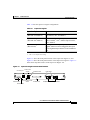
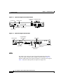
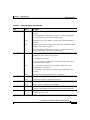
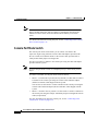
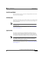
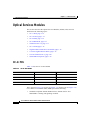
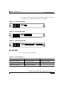
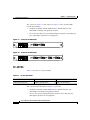
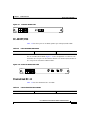
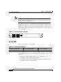
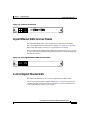
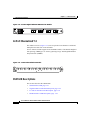
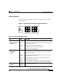
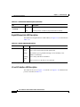
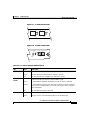
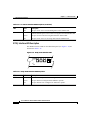
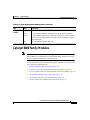
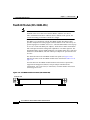
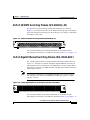
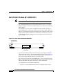
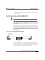
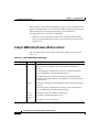
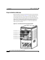
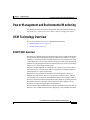
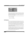
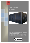
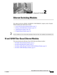
C H A P T E R
1
Product Overview
This chapter describes the Cisco 7600 series Internet Routers, supervisor engines,
Optical Services Modules (OSMs), and recommended Catalyst 6000 family
modules, and it contains these sections:
•
Cisco 7600 Series Internet Routers, page 1-1
•
Supervisor Engines, page 1-6
•
Optical Services Modules, page 1-14
•
Catalyst 6000 Family Modules, page 1-25
•
Port Addresses, page 1-31
•
Hot Swapping Supervisor Engines and Modules, page 1-33
•
Power Management and Environmental Monitoring, page 1-35
•
OSM Technology Overview, page 1-35
Cisco 7600 Series Internet Routers
The Cisco 7600 series Internet Routers consist of these routers:
•
Cisco 7603 Internet Router (3 slots)
•
Cisco 7606 Internet Router (6 slots)
•
Cisco 7609 Internet Router (9 vertical slots)
•
Cisco 7613 Internet Router (13 slots)
Cisco 7600 Series Internet Router Module Installation Guide
78-12798-07
1-1
Chapter 1
Product Overview
Cisco 7600 Series Internet Routers
Cisco 7600 series Internet Routers provide optical WAN and MAN networking
with a focus on line-rate delivery of high-touch IP services at the edge of service
providers networks.
•
Supported Hardware, page 1-2
•
Features, page 1-3
Supported Hardware
The Cisco 7600 series Internet Routers support the following hardware:
•
A supervisor engine with two Gigabit interface uplinks and an optional
redundant supervisor engine, in one of the following configurations:
– Supervisor Engine 1A with Multilayer Switch Feature Card 2 (MSFC2)
and Policy Feature Card (PFC) (Cisco 7603 Internet Router only)
– Supervisor Engine 2 with MSFC2 and PFC2
– Supervisor Engine 720 (Cisco 7609 Internet Router only)
The Supervisor Engine 720 can be installed in slot 5 of the
Cisco 7609 Internet Router. A redundant Supervisor Engine 720 can be
installed in slot 6.
•
Note
The supervisor engine and redundant supervisor engine must be
completely identical.
Note
The uplink ports are fully functional on the redundant supervisor
engine in standby mode.
Note
OSMs are not supported in the Cisco 7603 Internet Router with a
Supervisor Engine 1A.
Additional OSMs and recommended Catalyst 6000 family modules, in any
combination:
– Two additional modules for the Cisco 7603 Internet Router
Cisco 7600 Series Internet Router Module Installation Guide
1-2
78-12798-07
Chapter 1
Product Overview
Cisco 7600 Series Internet Routers
– Five additional modules for the Cisco 7606 Internet Router
– Eight additional modules for the Cisco 7609 Internet Router
– Twelve additional modules for the Cisco 7613 Internet Router
•
Hot-swappable fan assembly, redundant AC-input or DC-input power
supplies, and modules.
•
Redundant AC-input or DC-input power entry modules (PEMs) (Cisco 7603
and 7606 Internet Routers only).
•
Backplane that provides 32 Gbps of bandwidth; scalable up to 256 Gbps.
•
A Switch Fabric Module (WS-C6500-SFM or WS-X6500-SFM2)
The Switch Fabric Module can be installed in slot 5 of the Cisco 7606 or
Cisco 7609 Internet Router. A redundant Switch Fabric Module can be
installed in slot 6.
Note
The Switch Fabric Module is not supported on the Cisco 7603 Internet
Router.
Features
Table 1-1 lists some key features of the Cisco 7600 series Internet Router.
Cisco 7600 Series Internet Router Module Installation Guide
78-12798-07
1-3
Chapter 1
Product Overview
Cisco 7600 Series Internet Routers
Table 1-1
Cisco 7600 Series Internet Router Key Features
Feature
Description
Performance and
configuration
Refer to the Cisco 7600 Series Internet Router Software Configuration Guide for
detailed information about the features supported on the Cisco 7600 series
Internet Router.
Supervisor engine
•
Modular, upgradable feature modules for core switching logic
•
Two modular Gigabit Ethernet ports supporting these GBIC1 media types:
– 1000BASE-SX (WS-G5484)
– 1000BASE-LX/LH (WS-G5486)
– 1000BASE-ZX (WS-G5487)
Fault tolerance and
redundancy
•
MSFC2 and PFC2 or PFC support
•
PCMCIA slot
•
Console port for terminal and modem access
•
Support for two hot-swappable supervisor engines
•
Fast switchover for redundant supervisor engine and modules
•
Support for two redundant, AC- or DC-input, load-sharing power supplies
•
Support for two redundant AC- or DC-input PEMs (Cisco 7603 and 7606
Internet Routers only)
•
Power management for modules and power supplies
•
Environmental monitoring of critical system components
•
Hot-swappable fan assembly
•
Redundant clock modules
Cisco 7600 Series Internet Router Module Installation Guide
1-4
78-12798-07
Chapter 1
Product Overview
Cisco 7600 Series Internet Routers
Table 1-1
Cisco 7600 Series Internet Router Key Features (continued)
Feature
Memory
components
Description
•
512-KB NVRAM stores configuration information.
•
EEPROM2 component on the supervisor engine stores module-specific
information, such as the module serial number, part number, controller type,
hardware revision, configuration information, and other details unique to
each module.
•
256-MB DRAM for the default system software.
•
Bootflash—32-MB Flash memory stores the boot image.
•
16-MB Flash memory stores and runs software images.
•
PC Flash—One slot for 16- and 24-MB Flash PC cards (cards optional).
Use this additional Flash memory to store and run software images and
configuration files or to serve as an I/O device.
•
Flash file system—Flash memory contains a file system. You can use a
variety of commands to manage the file system (such as cd, pwd, dir, and
delete). The file system includes the following devices:
– Onboard bootflash
– PC Flash slot
Component
hot-swapping
Management
All components (including the optional redundant supervisor engine) and fans
support hot swapping, which allows you to add, replace, or remove components
without interrupting the system power or causing other software or interfaces to
shut down.
•
CLI through the console port or Telnet
•
Simple Network Management Protocol
1. GBIC = Gigabit Interface Converter
2. EEPROM = electrically erasable programmable read-only memory
Cisco 7600 Series Internet Router Module Installation Guide
78-12798-07
1-5
Chapter 1
Product Overview
Supervisor Engines
Supervisor Engines
Note
The Supervisor Engine 1A is supported only on the Cisco 7603 Internet
Router.
Note
The Supervisor Engine 720 is supported only on the Cisco 7609 Internet
Router.
This section describes the features on the Supervisor Engine 1A,
Supervisor Engine 2, and Supervisor Engine 720. This section contains the
following topics:
•
LEDs, page 1-8
•
Reset Button, page 1-11
•
Console Port, page 1-11
•
Console Port Mode Switch, page 1-12
•
Switch Load Meter, page 1-13
•
PCMCIA Slot, page 1-13
•
Uplink Ports, page 1-13
Cisco 7600 Series Internet Router Module Installation Guide
1-6
78-12798-07
Chapter 1
Product Overview
Supervisor Engines
Table 1-2 lists the supervisor engine configurations.
Table 1-2
Supervisor Engines
Supervisor Engine
Features
Supervisor Engine 1A
(WS-X6K-S1A-MSFC2)
Dual 1000BASE-X GBIC uplinks, with enhanced
QoS features, PFC, and MSFC2
Supervisor Engine 2
(WS-X6K-S2U-MSFC2)
Dual 1000BASE-X GBIC uplinks,
Fabric-enabled1, CEF2, Enhanced QoS features,
PFC2, MSFC2
Supervisor Engine 720
(WS-SUP720)
Two Gigabit Ethernet uplink ports; either two
Gigabit Small Form Factor Pluggable (SFP) ports
or one Gigabit SFP port and one 10/100/1000 RJ-45
port
1. Switch Fabric Module
2. CEF = Cisco Express Forwarding
Figure 1-1 shows the front panel features of the Supervisor Engine 1A, and
Figure 1-2 shows the front panel features of the Supervisor Engine 2. Figure 1-3
shows the front-panel features of the Supervisor Engine 720.
Figure 1-1
Supervisor Engine 1A Front Panel Features
Console port
Switch load
display
PCMCIA LED
LINK LEDs
WS-X6K-SUP1
PORT 2
SUPERVISOR I
Status LEDs
Console port mode
switch
PCMCIA slot
16057
EJECT
K
PORT 1
PCMCIA
LIN
1%
K
CONSOLE
Load
LIN
G
M
ET
R
ES
R
S
E
PW
U
TIV
ST
AT
SY
ST
AC
EM
M
T
Switch
CONSOLE 100%
PORT
MODE
1000BASE-X GBIC Uplink Ports
Reset button
Cisco 7600 Series Internet Router Module Installation Guide
78-12798-07
1-7
Chapter 1
Product Overview
Supervisor Engines
Figure 1-2
Supervisor Engine 2 Front Panel Features
Console port
Switch load 1000BASE-X GBIC
display
Uplink Ports
PCMCIA LED
WS-X6K-SUP2-2GE
PCMCIA
EJECT
PORT 2
1%
LIN
K
Status
LEDs
Console port
mode switch
PCMCIA slot
44312
ET
ES
CONSOLE
SUPERVISOR2
LIN
K
LE
G
PORT 1
R
S
EM
M
R
PW
U
SO
N
ST
AT
O
C
SY
ST
Load
M
T
Switch
100%
CONSOLE
PORT
MODE
LINK LEDs
Reset button
Figure 1-3
Supervisor Engine 720 Front Panel
CompactFlash
Type II slots
LINK LEDs
87890
Status LEDs
Disk LEDs
Console port
Gigabit Ethernet/10/100/1000
uplink port
Gigabit Ethernet
uplink port
LEDs
The LEDs on the supervisor engine front panel indicate the status of the
supervisor engine, modules, power supplies, and fan assembly. Table 1-3
describes LED operation for Supervisor Engine 1A and Supervisor Engine 2.
Table 1-4 describes LED operation for Supervisor Engine 720.
Cisco 7600 Series Internet Router Module Installation Guide
1-8
78-12798-07
Chapter 1
Product Overview
Supervisor Engines
Table 1-3
Supervisor Engines 1A and 2 LEDs
LED
Color
Description
STATUS
Orange
The module is booting or running diagnostics (normal initialization
sequence).
An overtemperature condition has occurred. (A minor threshold has
been exceeded during environmental monitoring.)
Green
All diagnostics pass; the module is operational (normal initialization
sequence).
Red
Diagnostic test failed; the module is not operational. (The fault occurred
during the initialization sequence.)
An overtemperature condition has occurred. (A major threshold has
been exceeded during environmental monitoring.)
SYSTEM1
Orange
The power supply or power supply fan failed.
Incompatible power supplies are installed.
The redundant clock failed.
One VTT2 module has failed or the VTT module temperature minor
threshold has been exceeded3.
Red
Two VTT modules failed or the VTT module temperature major
threshold has been exceeded3.
The temperature of the supervisor engine major threshold has been
exceeded.
ACTIVE
PWR
MGMT1
Green
All chassis environmental monitors are reporting OK.
Orange
The supervisor engine is in standby mode.
Green
The supervisor engine is operational and active.
Orange
Sufficient power is not available for all modules.
Green
Sufficient power is available for all modules.
SWITCH LOAD
If the system is operational, the switch load meter indicates (as an
approximate percentage) the current traffic load over the backplane.
PCMCIA
The PCMCIA LED is lit when no PCMCIA card is in the slot and goes
off when you insert a card.
Cisco 7600 Series Internet Router Module Installation Guide
78-12798-07
1-9
Chapter 1
Product Overview
Supervisor Engines
Table 1-3
Supervisor Engines 1A and 2 LEDs (continued)
LED
Color
Description
LINK
Orange
The link has been disabled by software.
Flashing
orange
The link is bad and has been disabled due to a hardware failure.
Green
The port is operational.
Off
No signal is detected.
1. The SYSTEM and PWR MGMT LED indications on a redundant supervisor engine are synchronized to the active supervisor
engine.
2. VTT = voltage termination module. The VTT module terminates signals on the system switching bus.
3. If no redundant supervisor engine is installed and there is a VTT module minor or major overtemperature condition, the
system shuts down.
Table 1-4
Supervisor Engine 720 LEDs
LED
Color
Description
STATUS
Orange
The module is booting or running diagnostics (normal initialization
sequence).
Green
All diagnostics pass; the module is operational (normal initialization
sequence).
Yellow
Minor hardware problems.
Red
An overtemperature condition has occurred. (A major threshold has
been exceeded during environmental monitoring.)
Orange
The module is powering up or a minor hardware fault has occurred.
Red
Major hardware problem.
SYSTEM1
The temperature of the supervisor engine major threshold has been
exceeded.
ACTIVE
Blinking
Red
Continuous backplane stall.
Green
All chassis environmental monitors are reporting OK.
Orange
The module is powering up or is in standby mode.
Green
The module is operational and active.
Cisco 7600 Series Internet Router Module Installation Guide
1-10
78-12798-07
Chapter 1
Product Overview
Supervisor Engines
Table 1-4
Supervisor Engine 720 LEDs (continued)
LED
Color
Description
Orange
The module is powering up or has minor hardware problems.
Red
Major hardware problem.
Green
Sufficient power is available for all modules.
Orange
The port is disabled.
Flashing
orange
The port is bad.
Green
The port is operational.
Off
The module is powering up or the port is enabled and there is no link.
DISK 0
Green
The disk is active.
DISK 1
Green
The disk is active.
PWR MGMT
LINK
1
1. The SYSTEM and PWR MGMT LED indications on a redundant supervisor engine are synchronized to the active supervisor
engine.
Reset Button
The Reset button allows you to restart the system.
Note
Use a ballpoint pen tip or other small, pointed object to access the Reset
button.
Console Port
The console port allows you to access the system either locally (with a console
terminal) or remotely (with a modem). The console port is an EIA/TIA-232
asynchronous, serial connection with hardware flow control and an RJ-45
connector.
Cisco 7600 Series Internet Router Module Installation Guide
78-12798-07
1-11
Chapter 1
Product Overview
Supervisor Engines
Note
EIA/TIA-232 and EIA/TIA-449 were known as recommended standards
RS-232 and RS-449 before their acceptance as standards by the Electronic
Industries Alliance (EIA) and Telecommunications Industry Association
(TIA).
For detailed information on using this port, see the “Connecting to the Console
Port” section on page 3-15.
Console Port Mode Switch
The console port mode switch allows you to connect a terminal to the
supervisor engine using either the console cable and adapters provided with
the Cisco 7600 series Internet Router or the console cable provided with a
Catalyst 5000 family Supervisor Engine III.
You also can connect a modem to the console port using the cable and adapter
provided with the system.
Note
To access the port mode switch, use a ballpoint pen tip or other small, pointed
object.
To connect a terminal, use the port mode switch as follows:
•
Mode 1—Switch in the in position (factory default). Use this mode to connect
a terminal to the console port using the console cable and DTE adapter
(labeled “Terminal”) that shipped with the system.
You can also use this mode to connect a modem to the console port using the
console cable and DCE adapter (labeled “Modem”) that shipped with the
system.
•
Mode 2—Switch in the out position. Use this mode to connect a terminal to
the console port using the Catalyst 5000 family Supervisor Engine III console
cable (not provided).
For more information on using the console port, see the “Connecting to the
Console Port” section on page 3-15.
Cisco 7600 Series Internet Router Module Installation Guide
1-12
78-12798-07
Chapter 1
Product Overview
Supervisor Engines
Switch Load Meter
The switch load meter provides you with a visual approximation of the current
traffic load across the backplane.
PCMCIA Slot
The Flash PC card (PCMCIA card) slot holds a Flash PC card for additional Flash
memory. You can use this Flash memory to store and run software images or to
serve as an I/O device.
Note
Throughout this publication, the term Flash PC card is used in place of the
term PCMCIA card.
For detailed information on using the Flash PC card, see the “Using Flash PC
Cards” section on page 3-23.
Uplink Ports
The supervisor engine provides two Gigabit Ethernet uplink ports that you
can configure with any combination of shortwave (SX), longwave/long-haul
(LX/LH), and extended reach (ZX) Gigabit Interface Converters (GBICs). The
two 1000BASE-X Gigabit Ethernet uplink ports operate in full-duplex mode only.
Note
In a redundant configuration with two supervisor engines, the uplink ports on
the redundant (standby) supervisor engine are active and can be used for
normal traffic like any other ports in the chassis.
For detailed information on these ports, see the “Connecting to the Uplink Ports”
section on page 3-17.
Cisco 7600 Series Internet Router Module Installation Guide
78-12798-07
1-13
Chapter 1
Product Overview
Optical Services Modules
Optical Services Modules
This section describes the Optical Services Modules (OSMs). This section is
divided into the following topics:
•
OC-3c POS, page 1-14
•
OC-12c POS, page 1-15
•
OC-48 POS, page 1-16
•
OC-48 DPT/POS, page 1-17
•
Channelized OC-12, page 1-17
•
OC-12 ATM, page 1-18
•
Gigabit Ethernet WAN Services Module, page 1-19
•
2+4-Port Gigabit Ethernet WAN, page 1-19
•
12-Port Channelized T-3, page 1-20
•
OSM LED Descriptions, page 1-20
OC-3c POS
Table 1-5 lists the OC-3c POS OSMs.
Table 1-5
OC-3c POS OSMs
OSM-4OC3-POS-MM+
OSM-4OC3-POS-SI
OSM-4OC3-POS-SI+
OSM-8OC3-POS-MM
OSM-8OC3-POS-MM+
OSM-8OC3-POS-SI
OSM-8OC3-POS-SI+
OSM-8OC3-POS-SL
OSM-8OC3-POS-SL+
OSM-16OC3-POS-MM
OSM-16OC3-POS-MM+
OSM-16OC3-POS-SI
OSM-16OC3-POS-SI+
OSM-16OC3-POS-SL
OSM-16OC3-POS-SL+
The 4-port (see Figure 1-4), 8-port (see Figure 1-5), and 16-port (see Figure 1-6)
OC-3 Packet-over-SONET (POS) OSMs provide the following:
•
Standards-compliant SONET/SDH interface; SONET/STS-3c and
SDH/STM-1c framing and signaling overhead.
Cisco 7600 Series Internet Router Module Installation Guide
1-14
78-12798-07
Chapter 1
Product Overview
Optical Services Modules
Four, eight, or sixteen MT-RJ fiber ports providing full-duplex operation at
155 Mbps per port. (Half-duplex operation is not supported.)
•
Figure 1-4
4-Port OC-3 POS OSM
68392
4
3
2
ET
4
LIN
K
LIN
K
R
ES
4
Figure 1-5
3
1
LIN
K
4 PORT OC3 POS MM
2
LIN
K
2
ST
AT
1
U
S
1
3
C
A
AL RR LIN
AR IE K
M R
OSM-4OC3-POS SI
8-Port OC-3 POS OSM
C
A
AL RR LIN
AR IE K
M R
3
5
6
7
8
5
6
7
8
45163
4
4
3
2
ET
K
4
LIN
LIN
3
K
1
Figure 1-6
2
LIN
LIN
K
8 PORT OC3 POS MM
K
R
ES
4
2
ST
AT
1
U
S
1
OSM-8OC3-POS MM
16-Port OC-3 POS OSM
C
A
AL RR LIN
AR IE K
M R
45164
16
15
14
13
11
12
9
10
3
2
ET
4
LIN
K
K
LIN
3
2
LIN
1
LIN
K
16 PORT OC-3 POS SM LR
K
R
ES
4
2
ST
AT
1
U
S
3
1
OSM-16OC3-POS-SL
OC-12c POS
Table 1-6 lists the OC-12c POS OSMs.
Table 1-6
OC-12c POS OSMs
OSM-2OC12-POS-SI
OSM-2OC12-POS-SL
OSM-2OC12-POS-MM+
OSM-2OC12-POS-SI+
OSM-2OC12-POS-SL+
OSM-4OC12-POS-MM
OSM-4OC12-POS-SI
OSM-4OC12-POS-SL
OSM-4OC12-POS-MM+
OSM-4OC12-POS-SI+
OSM-2OC12-POS-MM
Cisco 7600 Series Internet Router Module Installation Guide
78-12798-07
1-15
Chapter 1
Product Overview
Optical Services Modules
The 2-port (see Figure 1-7) and 4-port (see Figure 1-8) OC-12 POS OSMs
provide the following:
Standards-compliant SONET/SDH interface; SONET/STS-12c and
SDH/STM-4c framing and signaling overhead.
•
Two or four SC fiber ports providing full-duplex operation at 622 Mbps per
port. (Half-duplex operation is not supported.)
2-Port OC-12c POS OSM
45162
2
T
R
E
TX
R
TX
X
45161
R
PO
C
AR
AL RIE
AR R
M
3
T
R
PO
T4
R
X
R
C
AR
AL RIE
AR R
M
X
TIV
X
TX
R
TX
AC
E
TIV
AC
X
TX
R
2
T
R
C
AR
AL RIE
AR R
M
PO
R
T
1
R
R
K
4
LIN
LIN
3
K
C
AR
AL RIE
AR R
M
ET
ES
R
4
K
2
LIN
1
K
LIN
X
X
TX
TX
AC
X
TX
R
TIV
E
E
TIV
AC
3
1
S
U
AT
2
ST
PO
4-Port OC-12c POS OSM
OSM-4OC12 POS-SI
4 PORT OC-12 POS SM IR
TX
R
C
AR
AL RIE
AR R
M
1
4
LIN
K
C
AR
PO
R
T
AL RIE
AR R
M
ES
R
4
K
LIN
3
K
1
2
LIN
K
LIN
Figure 1-8
R
TX
X
X
R
ET
S
U
AT
ST
2
2 PORT OC-12 POS MM
X
TIV
AC
X
TX
R
AC
TX
3
1
TIV
E
E
OSM-2OC12-POS MM
PO
Figure 1-7
•
OC-48 POS
Table 1-7 lists the OC-12c POS OSMs.
Table 1-7
OC-12c POS OSMs
OSM-1OC48-POS-SL
OSM-1OC48-POS-SS
OSM-1OC48-POS-SI
OSM-1OC48-POS-SS+
OSM-1OC48-POS-SI+
OSM-1OC48-POS-SL+
The 1-port OC-48 POS OSM (see Figure 1-9) provides:
•
Standards-compliant SONET/SDH interface; SONET/STS-48c and
SDH/STM-16c framing and signaling overhead.
•
One SC fiber port providing full-duplex operation at 2.5 Gbps per port.
(Half-duplex operation is not supported.)
Cisco 7600 Series Internet Router Module Installation Guide
1-16
78-12798-07
Chapter 1
Product Overview
Optical Services Modules
Figure 1-9
1-Port OC-48 POS OSM
TX
R
X
45165
R
X
ET
C
AR
AL RIE
AR R
M
R
ES
LIN
K
4
LIN
K
3
LIN
K
1
2
LIN
K
1 PORT OC-48 POS SM SR
4
2
ST
AT
U
S
TX
1
3
AC
TIV
E
OSM-1OC48-POS-SS
OC-48 DPT/POS
Table 1-8 lists the 2-port OC-48 DPT(dynamic port transport)/POS OSMs.
Table 1-8
2-Port OC-48 DPT/POS OSMs
OSM-20C48/1DPT-SI
OSM-20C48/1DPT-SL
OSM-20C48/1DPT-SS
The OC-48 DPT)/POS OSMs (Figure 1-10) are configurable via software to be
used either as a two-port OC-48c/STM-16 Packet-over-SONET (POS) module or
as a one-port OC-48c/STM-16 DPT module.
Figure 1-10 2-Port OC-48 DPT/POS OSM
73361
ET
ES
4
K
K
LIN
4
LIN
3
K
LIN
2
LIN
1
2 PORT OC48 POS/DPT SN SR
K
R
2
ST
AT
U
S
1
3
OSM-20C48/IDPT-SS
Channelized OC-12
Table 1-9 lists the channelized OC-12 OSMs.
Table 1-9
1-Port Channelized OC-12 OSMs
OSM-1CHOC12/T1-SI
OSM-1CHOC12/T3-SI
Cisco 7600 Series Internet Router Module Installation Guide
78-12798-07
1-17
Chapter 1
Product Overview
Optical Services Modules
The CLI allows SDH framing and channel mappings although these
configurations are not supported currently. Do not configure the channelized
OC-12 modules for SDH framing.
Note
The 1-port (see Figure 1-11) channelized OC-12 OSMs support channelized
configurations down to OC-3 and DS3. The channelized OC-12 modules can be
configured as multiple OC-3 or DS3 channelized interfaces, or a mix of OC-3,
DS3, and DS3 subrate channelized interfaces. Each port uses LC fiber connectors
for use with SMF.
Figure 1-11 1-Port Channelized OC-12 OSM
X
TIV
AC
R
58471
1
C
AR
AL RIE
AR R
M
LIN
4
K
4
K
LIN
3
K
LIN
2
LIN
1
1 PORT CHOC12/STM4/T3/E3
K
2
ST
AT
U
S
1
3
TX
E
OSM-1CHOC12/T3-SI
OC-12 ATM
Table 1-10 lists the OC-12c ATM OSMs.
Table 1-10 2-Port OC-12 ATM Modules
OSM-2OC12-ATM-MM
OSM-2OC12-ATM-MM+
OSM-2OC12-ATM-SI
OSM-2OC12-ATM-SI+
The 2-port OC-12 Asynchronous Transfer Mode (ATM) OSM (see Figure 1-12)
provides:
•
Standards-compliant SONET/SDH interface; SONET/STS-3c and
SDH/STM-1c framing and signaling overhead.
•
Two SC fiber ports providing full-duplex operation at 622 Mbps per port
(half-duplex operation is not supported).
Cisco 7600 Series Internet Router Module Installation Guide
1-18
78-12798-07
Chapter 1
Product Overview
Optical Services Modules
Figure 1-12 2-Port OC-12 ATM OSM
E
TX
TX
R
X
AC
TIV
TX
R
X
45160
2
R
X
C
AR
AL RIE
AR R
M
1
PO
R
T
PO
R
T
AC
TIV
R
X
C
AR
AL RIE
AR R
M
4
LIN
K
4
3
LIN
K
1
2
LIN
K
2 PORT OC-12 ATM SM IR
LIN
K
2
ST
R
ES
AT
ET
U
S
TX
3
1
E
OSM-20C12-ATM-SI
Gigabit Ethernet WAN Services Module
The OSM-4GE-WAN-GBIC is the Gigabit Ethernet WAN Services Module.
The 4-port Gigabit Ethernet WAN Services Module (see Figure 1-13) provides
WAN router functionality with Layer 3 Gigabit Ethernet switching.
The four GBIC-based Gigabit Ethernet WAN ports support basic Layer 3 services
as well as Destination Sensitive Billing (DSB) and Versatile Traffic Management
and Shaping (VTMS).
Figure 1-13 4-Port Gigabit Ethernet WAN Services Module
3
4
LIN
K
4
K
LIN
3
K
1
2
LIN
LIN
4 PORT GE WAN SERVICES
1
ST
2
AT
45159
U
S
1
OSM-4GE-WAN-GBIC
2+4-Port Gigabit Ethernet WAN
The OSM-2+4GE-WAN+ is the 2+4-Port Giagabit Ethernet WAN OSM.
The 2+4-Port Giagabit Ethernet WAN OSM(Figure 1-14) provides support for
four WAN Gigabit Ethernet interfaces per module as well as an additional two
LAN Gigabit Ethernet interfaces per module.
Cisco 7600 Series Internet Router Module Installation Guide
78-12798-07
1-19
Chapter 1
Product Overview
Optical Services Modules
85345
Figure 1-14 2+4-Port Gigabit Ethernet WAN Services Module
12-Port Channelized T-3
The OSM-12CT3/T1 (Figure 1-15) can accept both clear-channel T3 trafficand
multiplexed circuits from T1/E1 and DS0.
Service features include support for IP and MPLS traffic, Class-Based Weighted
Fair Queuing (CBWFQ), Low-Latency Queuing (LLQ), and Weighted Random
Early Detection (WRED).
77886
Figure 1-15 12-Port Channelized T-3 Module
OSM LED Descriptions
This section describes the OSM LEDs:
•
OSM STATUS LED, page 1-21
•
Gigabit Ethernet Link LED Description, page 1-22
•
LC and SC Interface LED Description, page 1-22
•
MT-RJ Interface LED Description, page 1-24
Cisco 7600 Series Internet Router Module Installation Guide
1-20
78-12798-07
Chapter 1
Product Overview
Optical Services Modules
OSM STATUS LED
The STATUS LED on all OSMs (see Figure 1-16) provides module status as
shown in Table 1-11.
Figure 1-16 OSM STATUS and LINK LEDs—Gigabit Ethernet Ports
45166
K
4
LI
3
N
K
4
N
LI
K
2
LI
N
K
1
LI
N
4 PORT OC-12 POS MM
2
ST
AT
U
S
3
1
OSM-4OC12-POS-MM
Table 1-11 OSM STATUS LED Description
LED
Color
STATUS
Normal initialization
sequence
Fault during
initialization
sequence
Description
Indicates module status.
Red
Module is resetting (system has just been powered on or module
has been hot inserted).
Orange
Module is booting or running diagnostics.
Green
All diagnostics pass; module is operational.
Off
Module is not receiving power.
Red
The module fails to successfully download code and
configuration information during the initial reset; the module
does not come online.
Orange
to red
Any of the diagnostics fail, excluding port-specific tests; the
module does not come online.
Orange
to red
All the diagnostics pass, but all port-specific tests fail; the
module does not come online.
Orange
to green
All the diagnostic tests pass, but some of the port-specific tests
fail; the module comes online with the faulty ports disabled.
The module is disabled Green
through CLI
to orange
The module is not online.
Cisco 7600 Series Internet Router Module Installation Guide
78-12798-07
1-21
Chapter 1
Product Overview
Optical Services Modules
Table 1-11 OSM STATUS LED Description (continued)
LED
Environmental
monitoring
Color
Description
Orange
Overtemperature condition (minor threshold exceeded).
Red
Overtemperature condition (major threshold exceeded).
Gigabit Ethernet Link LED Description
The GBIC-based Gigabit Ethernet LINK LEDs (see Figure 1-16) are described in
Table 1-12.
Table 1-12 Module LINK LED Descriptions
LED
Color
LINK n
Description
Indicates port and link status.
Green
Port is active (link connected and operational).
Orange
The module or port is disabled through a CLI command, or the
module is initializing1.
Flashing
orange
Port is faulty and has been disabled.
Off
Port is not active or the link is not connected.
1. This is a good time to verify that all LINK LEDs are functioning.
LC and SC Interface LED Description
The LEDs for the LC (see Figure 1-17) and SC (see Figure 1-18) OSM interface
ports are described in Table 1-13.
Cisco 7600 Series Internet Router Module Installation Guide
1-22
78-12798-07
Chapter 1
Product Overview
Optical Services Modules
VE
X
R
X
58944
4
C
AR
AL RI
AR ER
M
R
C
AR
AL RI
AR ER
M
3
TX
TI
AC
X
R
TX
VE
TX
AC
TI
TX
R
X
Figure 1-17 LC OSM Interface LEDs
55749
T4
R
PO
C
AR
AL RI
AR ER
M
R
X
TX
AC
R
TX
X
TI
VE
Figure 1-18 SC OSM Interface LEDs
Table 1-13 LC and SC Interface LED Descriptions
LED
Color
ACTIVE
CARRIER
ALARM
Description
Indicates that the port has been configured and enabled.
Green
The port has been configured and enabled to operate.
Off
The port has not been configured or enabled to operate.
Indicates that the port detects a valid SONET signal.
Green
A valid SONET signal has been detected with no alarm conditions.
Yellow
A valid SONET signal has been detected, but there are alarm conditions
present (such as LRFI, PRFI, LOS, LOF, LOP, LAIS, PAIS, or Signal
Label Mismatch).
Off
No valid SONET signal is detected.
TX
Indicates that the port is active and transmitting data on the SONET link.
Green
The port is active and transmitting data on the SONET link.
Cisco 7600 Series Internet Router Module Installation Guide
78-12798-07
1-23
Chapter 1
Product Overview
Optical Services Modules
Table 1-13 LC and SC Interface LED Descriptions (continued)
LED
Color
Description
Off
The port is not active or transmitting data on the SONET link.
RX
Indicates that the port is active and receiving data from the SONET link.
Green
The port is active and receiving data from the SONET link.
Off
The port is not active or receiving data from the SONET link.
MT-RJ Interface LED Description
The MT-RJ interface LEDs on the OSM front panel (see Figure 1-19) are
described in Table 1-14.
55750
4
3
2
R
ES
ET
1
C
A
AL RR LIN
AR IE K
M R
Figure 1-19 MT-RJ OSM Interface LEDs
Table 1-14 MT-RJ OSM Interface LED Descriptions
LED
Color
LINK
Description
Indicates that the port has been configured and enabled.
Green
The port has been configured and enabled to operate.
Off
The port has not been configured or enabled to operate.
Cisco 7600 Series Internet Router Module Installation Guide
1-24
78-12798-07
Chapter 1
Product Overview
Catalyst 6000 Family Modules
Table 1-14 MT-RJ OSM Interface LED Descriptions (continued)
LED
CARRIER
ALARM
Color
Description
Indicates that the port detects a valid SONET signal.
Green
A valid SONET signal has been detected with no alarm conditions.
Yellow
A valid SONET signal has been detected, but there are alarm conditions
present (such as LRFI, PRFI, LOS, LOF, LOP, LAIS, PAIS, or Signal
Label Mismatch).
Off
No valid SONET signal is detected.
Catalyst 6000 Family Modules
Note
All Catalyst 6000 family modules are supported on the Cisco 7600 series
Internet Router. For information on Catalyst 6000 family modules, refer to the
Catalyst 6000 Family Module Installation Guide.
This section describes the recommended Catalyst 6000 family modules for the
Cisco 7600 series Internet Router:
•
FlexWAN Module (WS-X6182-2PA), page 1-26
•
48-Port 10/100TX Switching Module (WS-X6348-RJ-45), page 1-27
•
16-Port Gigabit Ethernet Switching Module (WS-X6516-GBIC), page 1-27
•
Switch Fabric Module (WS-C6500-SFM), page 1-28
•
Switch Fabric Module 2 (WS-X6500-SFM2), page 1-29
•
Catalyst 6000 Family Module LED Descriptions, page 1-30
Cisco 7600 Series Internet Router Module Installation Guide
78-12798-07
1-25
Chapter 1
Product Overview
Catalyst 6000 Family Modules
FlexWAN Module (WS-X6182-2PA)
Note
The FlexWAN module is not fabric-enabled. When a Switch Fabric Module is
installed in the Cisco 7600 series Internet Router, and there is a mix of
fabric-enabled and non-fabric-enabled (classic) modules in the system, the
central forwarding performance remains at 15 Mpps.
The MSFC2, in conjunction with the FlexWAN module (WS-X6182-2PA),
provides multiprotocol routing support with full Internet route connectivity for
speeds ranging from serial RS-232 to OC-3. The FlexWAN module can accept up
to two Cisco 7200/7500 WAN port adapters, which deliver WAN consolidation
and extend QoS and traffic management capabilities over WAN segments. The
FlexWAN module supports ATM and Packet over SONET (POS) OC-3 links and
channelized, multichannel, and clear channel port adapters at speeds from T1/E1
to T3/E3.
The STATUS LED on the FlexWAN module front panel (see Figure 1-20)
indicates the status of the FlexWAN module and is described in Table 1-15 on
page 1-30.
For information on FlexWAN module hardware and software requirements,
supported and unsupported features, and port adapter installation and
configuration, refer to the Catalyst 6000 Family FlexWAN Module Installation
and Configuration Note.
Figure 1-20 FlexWAN Module Front Panel (WS-X6182-2PA)
ST
AT
U
S
30178
STATUS LED
Cisco 7600 Series Internet Router Module Installation Guide
1-26
78-12798-07
Chapter 1
Product Overview
Catalyst 6000 Family Modules
48-Port 10/100TX Switching Module (WS-X6348-RJ-45)
The 48-port 10/100TX switching module (WS-X6348-RJ-45), shown in
Figure 1-21, provides 48 switched, 10/100-Mbps autosensing, full- or half-duplex
ports. Ports have RJ-45 connectors for either Category 3 or Category 5 unshielded
twisted-pair (UTP) cable.
Figure 1-21 48-Port 10/100TX Switching Module (WS-X6348-RJ-45)
48
47
46
45
44
43
42
41
40
39
38
37
36
35
34
33
32
31
30
29
28
27
26
PHONE
ETHERNET SWITCHING
MODULE
25
24
23
22
21
20
19
18
17
16
15
14
48 PORT
10/100 BASE-T
13
9
12
8
11
7
10
6
5
4
3
2
1
STATUS
39496
48
38
36
26
24
14
2
12
1
WS-X6348-RJ-45
The front-panel LEDs provide status information for the module and the
individual port connections. The LEDs are described in Table 1-15 on page 1-30.
16-Port Gigabit Ethernet Switching Module (WS-X6516-GBIC)
The 16-port Gigabit Ethernet switching module (WS-X6516-GBIC), shown in
Figure 1-22, provides 16 switched, full-duplex Gigabit Ethernet ports that you
can configure with any combination of 1000BASE-SX, LX/LH, and ZX GBICs.
Ports have SC connectors for MMF and SMF. The WS-X6516-GBIC module has
enhanced QoS features.
You can have a maximum of 12 1000BASE-ZX GBICs per system to comply
with EN55022 Class B and 24 1000BASE-ZX GBICs per system to comply
with FCC Class A.
Note
Figure 1-22 16-Port Gigabit Ethernet Switching Module (WS-X6516-GBIC)
WS-X6516-GBIC
3
5
7
9
11
13
15
2
4
6
8
10
12
14
16
16
44315
15
LIN
K
14
LIN
K
13
LIN
K
12
LIN
K
11
LIN
K
10
LIN
K
K
9
LIN
K
8
LIN
K
7
LIN
K
6
LIN
K
5
LIN
K
4
LIN
K
3
LIN
K
2
LIN
1
LIN
K
LIN
16 PORT GIGABIT ETHERNET
K
ST
A
TU
S
1
The front-panel LEDs provide status information for the module and the
individual port connections. The LEDs are described in Table 1-15 on page 1-30.
Cisco 7600 Series Internet Router Module Installation Guide
78-12798-07
1-27
Chapter 1
Product Overview
Catalyst 6000 Family Modules
Switch Fabric Module (WS-C6500-SFM)
Note
The Switch Fabric Module is not supported on the Cisco 7603 Internet Router.
The Switch Fabric Module (WS-C6500-SFM), shown in Figure 1-23,requires
Supervisor Engine 2 and must be installed in slots 5 or 6 of the Cisco 7600 series
Internet Router.
For redundancy, you can install a second Switch Fabric Module. The Switch
Fabric Module that is installed first functions as the primary module. When you
install two modules at the same time, the module in slot 5 functions as the primary
module, and the module installed in slot 6 functions as the backup. If you reset
the Switch Fabric Module installed in slot 5, the module in slot 6 becomes the
primary module.
Figure 1-23 Switch Fabric Module (WS-C6500-SFM)
STATUS LED
ACTIVE LED
LE
XT
NE
SWITCH FABRIC MDL
44313
SE
E
TIV
AT
ST
AC
US
CT
WS-C6500-SFM
2 Line X 20 character
LCD display
Two front-panel LEDs provide status information for the module and indicate
whether the module is active. The STATUS LED functions are listed in Table 1-15
on page 1-30. (The ACTIVE LED is green when the module is operational and
active, and is orange when the module is in standby mode.)
The front panel on the Switch Fabric Module has a 2-line by 20-character LCD
display. The display allows you to monitor the module’s input/output port traffic
and local bus traffic. The display also displays system information.
Two push buttons are used with the LCD display:
•
SELECT—Use this push button switch for LCD display menu selection.
Cisco 7600 Series Internet Router Module Installation Guide
1-28
78-12798-07
Chapter 1
Product Overview
Catalyst 6000 Family Modules
•
NEXT—Use this push button switch to scroll to the next item on the LCD
display menu.
Switch Fabric Module 2 (WS-X6500-SFM2)
Note
The Switch Fabric Module 2 is not supported on the Cisco 7603 Internet
Router.
The Switch Fabric Module 2 (WS-X6500-SFM2), shown in Figure 1-24, requires
a Supervisor Engine 2 and must be installed in slots 5 or 6 of the Cisco 7600 series
Internet Router.
For redundancy, you can install a second Switch Fabric Module 2. The Switch
Fabric Module 2 that is installed first functions as the primary module. When you
install two modules at the same time, the module in slot 5 functions as the primary
module, and the module installed in slot 6 functions as the backup. If you reset
the Switch Fabric Module 2 installed in slot 5, the module in slot 6 becomes the
primary module.
Figure 1-24 Switch Fabric Module 2 (WS-X6500-SFM2)
STATUS LED
ACTIVE LED
LE
XT
NE
SWITCH FABRIC MDL
51177
SE
E
TIV
AT
ST
AC
US
CT
WS-X6500-SFMIA
2 Line X 20 character
LCD display
Two front-panel LEDs provide status information for the module and indicate
whether the module is active. The STATUS LED functions are listed in Table 1-15
on page 1-30. (The ACTIVE LED is green when the module is operational and
active, and is orange when the module is in standby mode.)
Cisco 7600 Series Internet Router Module Installation Guide
78-12798-07
1-29
Chapter 1
Product Overview
Catalyst 6000 Family Modules
The front panel on the Switch Fabric Module 2 has a 2-line by 20-character LCD
display. The display allows you to monitor the module’s input/outport port traffic
and local bus traffic. The display also displays system information.
Two push buttons are used with the LCD display:
•
SELECT—Use this push button switch for LCD display menu selection.
•
NEXT—Use this push button switch to scroll to the next item on the LCD
display menu.
Catalyst 6000 Family Module LED Descriptions
The front-panel LEDs for the Catalyst 6000 family modules are described in
Table 1-15.
Table 1-15 Catalyst 6000 Family Module LEDs
LED
Color
Description
STATUS
Red
The module is resetting. (The system has just been powered on or the
module has been hot inserted—this is the normal initialization
sequence.)
An overtemperature condition has occurred. (A major threshold has
been exceeded during environmental monitoring.)
If the module fails to download code and configuration information
successfully during the initial reset, the LED stays red; the module does
not come online.
Orange
The module is booting or running diagnostics (the normal initialization
sequence).
An overtemperature condition has occurred. (A minor threshold has
been exceeded during environmental monitoring.)
Green
All diagnostics pass; the module is operational.
Green to
Orange
The module is disabled through the CLI1.
Off
The module is not receiving power.
Cisco 7600 Series Internet Router Module Installation Guide
1-30
78-12798-07
Chapter 1
Product Overview
Port Addresses
Table 1-15 Catalyst 6000 Family Module LEDs (continued)
LED
Color
Description
LINK
Green
The port is active (link connected and operational).
Orange
The module or port is disabled through the CLI command or the module
is initializing2.
Flashing
orange
The port is faulty and has been disabled.
Off
The port is not active or the link is not connected.
1. CLI = command-line interface.
2. This is a good time to verify that all LINK LEDs are functioning.
Port Addresses
Each port (or interface) in the Cisco 7600 series Internet Router is designated by
several different types of addresses. The physical interface address is the actual
physical location (slot and port) of the interface connector within the chassis. The
system software uses the physical addresses to control activity within the system
and to display status information. These physical slot and port addresses are not
used by other devices in the network; they are specific to the individual router and
its internal components and software. For more information, see the “Physical
Interface Addresses” section on page 1-32.
The MAC address is a standardized data link layer address that is required for
every port or device that connects to a network. Other devices in the network use
these addresses to locate specific ports in the network and to create and update
routing tables and data structures. The routers use a unique method, described in
the “MAC Addresses” section on page 1-33, to assign and control the MAC
addresses of their interfaces.
Cisco 7600 Series Internet Router Module Installation Guide
78-12798-07
1-31
Chapter 1
Product Overview
Port Addresses
Physical Interface Addresses
Physical port addresses specify the actual physical location of each module port
on the rear of the router, as shown in Figure 1-25. (The port numbering convention
is the same in the three-slot, six-slot, and nine-slot chassis.) The address is a
two-part number in the format slot/port number. The first number identifies the
slot in which the module is installed. Module slots are numbered from right to left
starting with 1. The second number identifies the physical port number on the
module. The port numbers always begin at 1 and are numbered from top to
bottom. The number of additional ports (n/1, n/2, and so on) depends on the
number of ports on the module.
Figure 1-25 Cisco 7609 Internet Router Port Address Examples
FAN
STATUS
US
AT
WS-X6K-SUP2-2GE
EM
ST
E
R
PW
OL
NS
E
PW
OL
NS
CO
CO
EM
SY
ST
SY
US
ST
AT
ST
R
T
SE
MT
MG
T
SE
RE
MT
RE
MG
CONSOLE
CONSOLE
NK 2
LI
3
4
CONSOLE
PORT
MODE
LI
NK 4
LI
LIN
K
T
R
IE
M
2
TX
RX
TX
RX
RX
1
1
TX
RT
PO
RT
PO
RX
RX
1
3
RT
3
PO
PCMCIA
PCMCIA
VE
TI
AC
TX
RX
2
VE
TI
AC
VE
TI
AC
1
RR
CA AR
AL
1
R
IE
RR M
CA AR
AL
R
IE
M
RR
CA AR
AL
SE
RE
T
SE
RE
T
SE
RE
T
SE
NK
LI IER
RR M
CA AR
AL
R
IE
M
RR
CA AR
AL
5
VE
VE
TX
RX
TI
AC
5
TI
AC
VE
TI
AC
R
IE
R
IE
RR M
RR M
CA AR
AL
CA AR K
AL LIN
R
IE
M
EJECT
TX
4
EJECT
TX
RR
CA AR
AL
4
TX
RX
TX
RX
6
RX
6
RX
2
7
2
TX
RT
PO
RT
PO
2
RX
RT
PO
7
100%
TX
RX
TX
RX
Load
VE
Load
TI
AC
Switch
R
IE
M
Switch
1%
100%
1%
RR
CA AR
AL
TX
RX
VE
TI
AC
SE
LE
CT
R
IE
M
VE
TI
AC
8
NE
XT
RR
CA AR
AL
R
IE
M
SE
LE
CT
TX
TX
RR
CA AR
AL
8
NE
XT
RX
RX
3
K
PORT 1
K
LIN
LIN
TX
TX
RR
CA AR
AL
PORT 1
3
TX
R
IE
M
RR
CA AR
AL
VE
TI
AC
TX
RX
VE
TI
AC
VE
TI
AC
R
IE
RR M
CA AR K
AL LIN
R
IE
M
TX
RX
TX
RX
Port numbers 9/1 to 9/8
RT
PO
RT
PO
3
RX
RT
PO
Port numbers 8/1 to 8/8
RX
RX
RX
TX
TX
PORT 2
K
PORT 2
LIN
TX
55748
T
SE
RE
RE
NK
LI IER
M
RR
CA AR
AL
NK 4
LI
NK 4
NK
NK
4 LI
4 LI
CONSOLE
PORT
MODE
NK 3
LI
NK 3
3
LI
NK 3
3
4
LI
3
Port numbers 7/1 to 7/4
SUPERVISOR2
1
NK 1
3
4
NK
LI
NK
LI
Port numbers 4/1 to 4/4
WS-X6K-SUP2-2GE
SUPERVISOR2
OSM-40C12-POS-MM
US
LI
NK 2
LI
NK 2
LI
NK
3
4
Port numbers 3/1 to 3/4
AT
2
3
NK 1
LI
AC
TIV
E
2 LI
NK
Port numbers 2/1 to 2/2
ST
4
1
2 LI
1
AC
TIV
E
NK 1
1
2
LI
NK
ST
AT
US
OC12 POS MM
OSM-40C12-POS-MM
US
AT
ST
OC12 POS MM
1
2
SWITCH FABRIC MDL
WS-C6500-SFM
WS-C6500-SFM
US
AT
1
2
ST
AT
US
LI
NK
LI
SWITCH FABRIC MDL
1
2
OSM-40C12-POS-MM
ST
OC12 POS MM
OSM-8OC3-POS MM
US
AT
ST
8 PORT OC3 POS MM
US
AT
ST
OSM-8OC3-POS MM
8 PORT OC3 POS MM
Port numbers 1/1 to 1/2
o
o
INPUT
OK
FAN
OK
OUTPUT
FAIL
INPUT
OK
FAN
OK
OUTPUT
FAIL
Cisco 7600 Series Internet Router Module Installation Guide
1-32
78-12798-07
Chapter 1
Product Overview
Hot Swapping Supervisor Engines and Modules
Interface ports maintain the same address regardless of whether other modules are
installed or removed. However, when you move a module to a different slot, the
first number in the address changes to reflect the new slot number. For example,
on a 4-port OC-12c POS OSM in slot 4 of the Cisco 7609 Internet Router, the
address of the top WAN port is 4/1, and the address of the bottom WAN port is
4/4. If you remove the 4-port OC-12c POS OSM from slot 4 and install it in slot 7,
the addresses of those same WAN ports become 7/1 through 7/4.
You can identify module ports by checking the slot and port location on the router.
You can also use software commands to display information about a specific
interface, or all interfaces, in the system. To display information about every
interface, enter the show interfaces command without parameters. To display
information about a specific interface, enter the show interfaces type command
(type being either POS or ATM) with the module (slot) number and port number
in the format show interfaces type [mod/port].
MAC Addresses
All network interface connections (ports) require a unique MAC address. The
MAC address of an interface is stored in electrically erasable programmable
read-only memory (EEPROM) on a component that resides directly on the
interface circuitry. The router system code reads the EEPROM for each interface
in the system, learns the MAC addresses, and then initializes appropriate
hardware and data structures. Each VLAN in the spanning tree has one unique
MAC address. This addressing scheme gives the router the intelligence to identify
the state (connected or not connected) of each interface. When you hot swap a
module, the MAC address changes with the module.
Hot Swapping Supervisor Engines and Modules
The Cisco 7600 series Internet Router provides a feature for removing and
replacing the redundant supervisor engine, OSMs, and Catalyst 6000 family
modules without powering down the system. This feature is known as hot
swapping.
Cisco 7600 Series Internet Router Module Installation Guide
78-12798-07
1-33
Chapter 1
Product Overview
Hot Swapping Supervisor Engines and Modules
Note
Although the FlexWAN module supports hot swapping, individual port
adapters do not. To replace port adapters, you must first remove the FlexWAN
module from the chassis and then replace port adapters as required.
When you remove or insert a module while the router is powered on and
operating, the system does the following:
1.
Determines if there is sufficient power for the module.
2.
Scans the backplane for configuration changes.
3.
Initializes all newly inserted modules, notes any removed modules, and
places them in the administratively shutdown state.
4.
Places any previously configured interfaces on the module back to the state
they were in when they were removed. Any newly inserted interfaces are put
in the administratively shutdown state, as if they were present (but
unconfigured) at boot time. If you insert a similar module type into a slot, its
ports are configured and brought online up to the port count of the original
module.
The system runs diagnostic tests on any new interfaces. If the test passes, the
system is operating normally. If the new module is faulty, the system resumes
normal operation but leaves the new interface disabled.
If the diagnostic test fails, the system crashes, which usually indicates that the
new module has a problem in the bus and should be removed.
When you install two supervisor engines, hot swapping allows you to remove and
replace one of the supervisor engines without turning off the system power.
Caution
To avoid erroneous failure messages, note the current configuration of all
interfaces before you remove or replace another module, and allow at least
15 seconds for the system to reinitialize after a module has been removed or
replaced.
Cisco 7600 Series Internet Router Module Installation Guide
1-34
78-12798-07
Chapter 1
Product Overview
Power Management and Environmental Monitoring
Power Management and Environmental Monitoring
For detailed information on power management and environmental monitoring,
refer to the Cisco 7600 Series Internet Router Software Configuration Guide.
OSM Technology Overview
This section provides an overview of SONET/SDH and ATM:
•
SONET/SDH Overview, page 1-35
•
ATM Overview, page 1-36
SONET/SDH Overview
The Packet over SONET (POS) specification defines the use of PPP encapsulation
over SONET/Synchronous Digital Hierarchy (SDH) links. SONET is an ANSI
standard (T1.1051988) for optical digital transmission at hierarchical rates from
51.840 Mbps (STS-1) to 2.5 Gbps (STS-48) and greater. SDH is the international
standard for optical digital transmission at hierarchical rates from 155.520 Mbps
(STM-1) to 2.5 Gbps (STM-16) and greater.
Because a SONET/SDH link is considered to be a point-to-point circuit, PPP is
well suited for use over these links. PPP was designed as a standard method of
communicating over point-to-point links.
SONET is an octet-synchronous multiplex scheme that defines a family of
standard rates and formats. The basic rate for POS is STS-3c/STM-1, which is
155.520 Mbps. The available information bandwidth is 149.760 Mbps, which is
the STS-3c/STM-1 Synchronous Payload Envelope (SPE), the payload portion of
the SONET frame into which the octet-oriented user data is mapped. (Octet
boundaries are aligned with the SPE octet boundaries.)
The International Telecommunications Union Telecommunication Sector (ITU-T)
defines a series of SDH transmission rates beginning at 155.520 Mbps as follows:
Cisco 7600 Series Internet Router Module Installation Guide
78-12798-07
1-35
Chapter 1
Product Overview
OSM Technology Overview
SONET1
SDH Equivalent
STS-3c
STM-1
STS-12c
STM-4c
STS-48c
STM-16c
1. ANSI-defined SONET specifications
SONET is not limited to optical links. Electrical specifications have been defined
for single-mode fiber, multimode fiber, and CATV 75-ohm coaxial cable. OSMs
currently allow transmission only over single-mode and multimode optical fiber.
Transmission rates are integral multiples of 51.840 Mbps, which can be used to
carry T3/E3 bit-synchronous signals.
The following transmission multiples are currently specified and commonly used:
•
STS-3c—155.520 Mbps
•
STS-12c—622.080 Mbps
•
STS-48c—2,488.320 Mbps
ATM Overview
ATM uses cell-switching and multiplexing technology that combines the features
of circuit switching (constant transmission delay and guaranteed capacity) with
the features of packet switching (flexibility and efficiency for intermittent traffic).
ATM is a connection-oriented environment. All traffic to or from an ATM network
is prefaced with a virtual path identifier (VPI) and virtual channel identifier
(VCI). A VPI/VCI pair is considered a single virtual circuit. Each virtual circuit
is a private connection to another node on the ATM network. Each virtual circuit
is treated as a point-to-point mechanism to another router or host and is capable
of supporting bidirectional traffic.
Each ATM node is required to establish a separate connection to every other node
in the ATM network that it must communicate with. All of these connections are
established using a permanent virtual circuit (PVC), which a network operator
configures, or an switched virtual circuit (SVC), which is set up and torn down
with an ATM signaling mechanism. This signaling is based on the ATM Forum
User-Network Interface (UNI) Specification V3.x, 4.0.
Cisco 7600 Series Internet Router Module Installation Guide
1-36
78-12798-07