1
EPSON
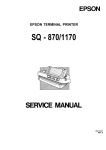
EPSON TERMINAL PRINTER
FX-870/1170
SERVICE MANUAL
4001461
REV.-A
.-.
..
&
{’”’
-.. ,
NOTICE
“ All rights reserved. Reproduction of any part of this manual in any from
whatsoever without SEIKO EPSON’s express written permission is forbidden.
“ The contents of this manual are subject to change without notice.
“ All efforts have been made to ensure the accuracy of the contents of this manual.
However, should any errors be detected, SEIKO EPSON would greatly appreciate
being informed of them.
“ The above notwithstanding SEIKO EPSON can assume no responsibility for any
errors in this manual or the consequences thereof.
@ Copyright 1992 by SEIKO EPSON CORPORATION
Nagano, Japan
-i-
REV.-A
PRECAUTIONS
Precautionary notations throughout the text are categorized relative to 1 ) personal injury, and 2) damage
to equipment:
DANGER
Signals a precaution which, if ignored, could result in serious or fatal personal
injury. Great caution should be exercised in performing procedures preceded by
a DANGER headings.
WARNING
Signals a precaution which, if ignored, could result in damage to equipment.
The precautionary measures itemized below should always be observed when performing repair/maintenance procedures.
DANGER
1 ALWAYS DISCONNECT THE PRODUCT FROM BOTH THE POWER SOURCE AND THE
HOST COMPUTER BEFORE PERFORMING ANY MAINTENANCE OR REPAIR
PROCEDURE.
2, NO WORK SHOULD BE PERFORMED ON THE UNIT BY PERSONS UNFAMILIAR WITH
BASIC SAFETY MEASURES AS DICTATED FOR ALL ELECTRONICS TECHNICIANS IN
THEIR LINE OF WORK.
3< WHEN PERFORMING TESTING AS DICTATED WITHIN THIS MANUAL, DO NOT
CONNECT THE UNIT TO A POWER SOURCE UNTIL INSTRUCTED TO DO SO. WHEN
THE POWER SUPPLY CABLE MUST BE CONNECTED, USE EXTREME CAUTION IN
WORKING ON POWER SUPPLY AND OTHER ELECTRONIC COMPONENTS.
WARNING
1. REPAIRS ON EPSON PRODUCT SHOULD BE PERFORMED ONLY BY AN EPSON
CERTIFIED REPAIR TECHNICIAN.
2. MAKE CERTAIN THAT THE SOURCE VOLTAGE IS THE SAME AS THE RATED
VOLTAGE, LISTED ON THE SERIAL NUMBER/RATING PLATE. IF THE EPSON PRODUCT HAS A PRIMARY-AC RATING DIFFERENT FROM THE AVAILABLE POWER
SOURCE, DO NOT CONNECT IT TO THE POWER SOURCE.
3. ALWAYS VERIFY THAT THE EPSON PRODUCT HAS BEEN DISCONNECTED FROM THE
POWER SOURCE BEFORE REMOVING OR REPLACING PRINTED CIRCUIT BOARDS
AND/OR INDIVIDUAL CHIPS.
4. IN ORDER TO PROTECT SENSITIVE /.LP CHIPS AND CIRCUITRY, USE STATIC
DISCHARGE EQUIPMENT, SUCH AS ANTI-STATIC WRIST STRAPS, WHEN ACCESSING INTERNAL COMPONENTS.
5. REPLACE MALFUNCTIONING COMPONENTS ONLY WITH THOSE COMPONENTS
RECOMMENDED BY THE MANUFACTURER; INTRODUCTION OF SECOND-SOURCE
ICS OR OTHER NONAPPROVED COMPONENTS MAY DAMAGE THE PRODUCT AND
VOID ANY APPLICABLE EPSON WARRANTY.
– ii -
REV.-A
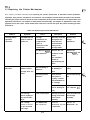
PREFACE
This manual describes functions, theory of electrical and mechanical
operations, maintenance, and repair of the FX-870/l 170.
The instructions and procedures included herein are intended for the
experienced repair technician, and attention should be given to the
precautions on the preceding page. The chapters are organized as follows:
Chapter 1 -
Provides a general product overview, lists specifications,
and illustrates the main components of the printer.
Chapter 2 -
Describes the theory of printer operation.
Chapter 3 -
Includes a step-by-step guide for product disassembly and
assembly.
Chapter 4 -
Includes a step-by-step guide for adjustment.
Chapter 5 -
Provides Epson-approved techniques for troubleshooting.
Chapter 6 -
Describes preventive maintenance techniques.
●
The contents of this manual are subject to change without notice.
- iv -
.
,. :;: \
f
..
REVISION SHEET
REVISON
DATE ISSUED
CHANGE DOCUMENT
A
June 15, 1992
1st issue
* ‘?:
(“
.7,,
-v–
REV.-A
TABLE OF CONTENTS
CHAPTER 1.
CHAPTER 2.
CHAPTER 3.
CHAPTER 4.
CHAPTER 5.
CHAPTER 6,
APPENDIX
GENERAL DESCRIPTION
OPERATING PRINCIPLES
DISASSEMBLY AND ASSEMBLY
ADJUSTMENTS
TROUBLESHOOTING
MAINTENANCE
– vi -
REV.-A
CHAPTER 1
GENERAL DESCRIPTION
1-1
1.1 Scope . . . . . . . . . . . . . . . . . . . . . . . . . . . . . . . . . . . . . . . . . . . . . . . . . . . . . . . . . . . . . . . . . . . . . . . . . . . . . . . . . . . . . . . . . . . . . . . . . . . . . . . . . . . . . . . .
...
1.1.1 Features . . . . . . . . . . . . . . . . . . . . . . . . . . . . . . . . . . . . . . . . . . . . . . . . . . . . . . . . . . . . . . . . . . . . . . . . . . . . . . . . . . . . . . . . . . . .1-1
1.1.2 Options . . . . . . . . . . . . . . . . . . . . . . . . . . . . . . . . . . . . . . . . . . . . . . . . . . . . . . . . . . . . . . . . . . . . . . . . . . . . . . . . . . . . . . . . . . . . . . . . 1-3
....
1.2 Specifications. . . . . . . . . . . . . . . . . . . . . . . . . . . . . . . . . . . . . . . . . . . . . . . . . . . . . . . . . . . . . . . . . . . . . . . . . . . . . . . . . . . . . . . . . . . . . . . 1-4
..
1.2.1 Hardware Specifications. . . . . . . . . . . . . . . . . . . . . . . . . . . . . . . . . . . . . . . . . . . . . . . . . . . . . . . . . . . . . . . . . .1-4
1-4
1.2.1.1 Printing Method ., . . . . . . . . . . . . . . . . . . . . . . . . . . . . . . . . . . . . . . . . . . . . . . . . . . . . . . . . . . . . . . . . . .
..
1.2.1.2 Paper Handling . . . . . . . . . . . . . . . . . . . . . . . . . . . . . . . . . . . . . . . . . . . . . . . . . . . . . . . . . . . . . . . . . . . .1-4
..
1.2.1.3 Paper Specifications . . . . . . . . . . . . . . . . . . . . . . . . . . . . . . . . . . . . . . . . . . . . . . . . . . . . . . . . . . .1-6
..
1.2.1.4 Printable Area . . . . . . . . . . . . . . . . . . . . . . . . . . . . . . . . . . . . . . . . . . . . . . . . . . . . . . . . . . . . . . . . . . . . . .1-9
..
1.2.1.5 Ribbon Cattridge . . . . . . . . . . . . . . . . . . . . . . . . . . . . . . . . . . . . . . . . . . . . . . . . . . . . . . . . . . . . . . .1-11
..
1.2.1.6 Electrical Specifications. . . . . . . . . . . . . . . . . . . . . . . . . . . . . . . . . . . . . . . . . . . . . . . . . . . . 1-12
1-12
1.2.1.7 Environmental Conditions . . . . . . . . . . . . . . . . . . . . . . . . . . . . . . . . . . . . . . . . . . . . . . . . .
...
1.2.1.8 Reliability . . . . . . . . . . . . . . . . . . . . . . . . . . . . . . . . . . . . . . . . . . . . . . . . . . . . . . . . . . . . . . . . . . . . . . . . . . 1-13
..
1.2.1.9 Safety Approvals . . . . . . . . . . . . . . . . . . . . . . . . . . . . . . . . . . . . . . . . . . . . . . . . . . . . . . . . . . . . . . .1-13
..
1.2.2 Firmware Specifications . . . . . . . . . . . . . . . . . . . . . . . . . . . . . . . . . . . . . . . . . . . . . . . . . . . . . . . . . . . . . . . .1-13
1-13
1.2.2.1 Print Control . . . . . . . . . . . . . . . . . . . . . . . . . . . . . . . . . . . . . . . . . . . . . . . . . . . . . . . . . . . . . . . . . . . . . . . .
..
1.2.2.2 Input Data Buffer . . . . . . . . . . . . . . . . . . . . . . . . . . . . . . . . . . . . . . . . . . . . . . . . . . . . . . . . . . . . . . .1-14
1-15
1.3 Interface . . . . . . . . . . . . . . . . . . . . . . . . . . . . . . . . . . . . . . . . . . . . . . . . . . . . . . . . . . . . . . . . . . . . . . . . . . . . . . . . . . . . . . . . . . . . . . . . . . . . . . . . . .
...
1.3.1 Parallel Interface . . . . . . . . . . . . . . . . . . . . . . . . . . . . . . . . . . . . . . . . . . . . . . . . . . . . . . . . . . . . . . . . . . . . . . . . . . . . 1-15
1-17
1.3.2 Optional Interface . . . . . . . . . . . . . . . . . . . . . . . . . . . . . . . . . . . . . . . . . . . . . . . . . . . . . . . . . . . . . . . . . . . . . . . . . . . . .
....
1.4 Control Panel . . . . . . . . . . . . . . . . . . . . . . . . . . . . . . . . . . . . . . . . . . . . . . . . . . . . . . . . . . . . . . . . . . . . . . . . . . . . . . . . . . . . . . . . . . . . . 1-17
...
1.4.1 Components . . . . . . . . . . . . . . . . . . . . . . . . . . . . . . . . . . . . . . . . . . . . . . . . . . . . . . . . . . . . . . . . . . . . . . . . . . . . . . . . . . .1-17
...
1.4.2 Buttons . . . . . . . . . . . . . . . . . . . . . . . . . . . . . . . . . . . . . . . . . . . . . . . . . . . . . . . . . . . . . . . . . . . . . . . . . . . . . . . . . . . . . . . . . . .1-18
...
1.4.3 Indicators . . . . . . . . . . . . . . . . . . . . . . . . . . . . . . . . . . . . . . . . . . . . . . . . . . . . . . . . . . . . . . . . . . . . . . . . . . . . . . . . . . . . . . . .1-19
1-20
1.5 Functions . . . . . . . . . . . . . . . . . . . . . . . . . . . . . . . . . . . . . . . . . . . . . . . . . . . .. .. . . . . . . . . . . . . . . . . . . . . . . . . . . . . . . . . . . . . . . . . . . . . . . . . .
1.5.1 Default Settings . . . . . . . . . . . . . . . . . . . . . . . . . . . . . . . . . . . . . . . . . . . . . . . . . . . . . . . . . . . . . . . . . . . . . . . . . . . . . . . . 1-20
..
1.5.2 Power On Default Settings . . . . . . . . . . . . . . . . . . . . . . . . . . . . . . . . . . . . . . . . . . . . . . . . . . . . . . . . . . . .1-23
...
1.5.3 Buffer-full Printing . . . . . . . . . . . . . . . . . . . . . . . . . . . . . . . . . . . . . . . . . . . . . . . . . . . . . . . . . . . . . . . . . . . . . . . . . 1-23
...
1.5.4 Hexadecimal Dump. . . . . . . . . . . . . . . . . . . . . . . . . . . . . . . . . . . . . . . . . . . . . . . . . . . . . . . . . . . . . . . . . . . . . . . . 1-23
1-24
1.5.5 Self Test . . . . . . . . . . . . . . . . .. . . . . . . . . . . . . . . . . . . . . . . . . . . . . . . . . . . . . . . . . . . . . . . . . . . . . . . . . . . . . . . . . . . . . . . . . . . .
..
1.5.6 Paper-out Detection. . . . . . . . . . . . . . . . . . . . . . . . . . . . . . . . . . . . . . . . . . . . . . . . . . . . . . . . . . . . . . . . . . . . . . . .1-24
..
1.5.7 Auto Tear-off . . . . . . . . . . . . . . . . . . . . . . . . . . . . . . . . . . . . . . . . . . . . . . . . . . . . . . . . . . . . . . . . . . . . . . . . . . . . . . . . . .1-24
...
1.5.8 Thermal Protection . . . . . . . . . . . . . . . . . . . . . . . . . . . . . . . . . . . . . . . . . . . . . . . . . . . . . . . . . . . . . . . . . . . . . . . . 1-24
1-24
1.5.9 High Duty Printing . . . . . . . . . . . . . . . . . . . . . . . . . . . . . . . . . . . . . . . . . . . . . . . . . . . . . . . . . . . . . . . . . . . . . . . . . . . .
.
1.5.10 Sheet Loading and Sheet Ejection. . . . . . . . . . . . . . . . . . . . . . . . . . . . . . . . . . . . . . . . . . . . . . .1-25
..
1.5.11 Adjust Lever Operation . . . . . . . . . . . . . . . . . . . . . . . . . . . . . . . . . . . . . . . . . . . . . . . . . . . . . . . . . . . . . . . .1-25
..
1.5.12 Printer Initialization . . . . . . . . . . . . . . . . . . . . . . . . . . . . . . . . . . . . . . . . . . . . . . . . . . . . . . . . . . . . . . . . . . . . . .1-26
1.5.13 Buzzer ................. o.... . . . . . . . . . . . . . . . . . . . . . . . . . . . . . . . . . . . . . . . . . . . . . . . . . . . . . . . . . . . . . . . . . . . . . . . . 1-27
l-i
REV.-A
1.6 Main Components ~~ti...m-.--.--...--.-.m.m..-.mm. ........................................1-28
1.6.1 BOARDASSEMBLY,C094MAlN(Main ControlCircuitBoard) ............1-29
1.6.2 BOARDASSEMBLY,C094PNL(Control Pand~HtiWd) .....-.l-3O
1.6.3 BOARD ASSEMBLY, C076PSBFSE (Power SuPPIY circuit Board) ......1 -30
...
1.6.4 Printer Mechanism . . . . . . . . . . . . . . . . . . . . . . . . . . . . . . . . . . . . . . . . . . . . . . . . . . . . . . . . . . . . . . . . . . . . . . . . . 1-31
...
1.6.5 Housing Assembly . . . . . . . . . . . . . . . . . . . . . . . . . . . . . . . . . . . . . . . . . . . . . . . . . . . . . . . . . . . . . . . . . . . . . . . . . 1-32
LIST OF FIGURES
..
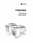
Figure 1-1. External View of FX-870/1170 . . . . . . . . . . . . . . . . . . . . . . . . . . . . . . . . . . . . . . . . . . . . . . . . . . . . . . . . . . 1-2
1-4
.
.
.
.
.
.
.
.
.
.
.
.
.
.
.
.
.
.
.
.
.
.
.
.
.
.
.
.
.
.
.
.
.
.
.
.
.
.
.
.
.
.
.
.
.
.
.
.
.
.
.
.
.
.
.
.
.
.
.
.
.
.
.
.
.
.
.
.
.
.
.
.
.
.
.
.
.
...
Figure 1-2. Pin Configuration.
..
Figure 1-3. Printable Area for Cut Sheets. . . . . . . . . . . . . . . . . . . . . . . . . . . . . . . . . . . . . . . . . . . . . . . . . . . . . . . . . . .1-9
.
Figure 1-4. Printable Area for Continuous Paper. . . . . . . . . . . . . . . . . . . . . . . . . . . . . . . . . . . . . . . . . . . . . .1-1o
..
Figure 1-5. Printable Area for Roll Paper . . . . . . . . . . . . . . . . . . . . . . . . . . . . . . . . . . . . . . . . . . . . . . . . . . . . . . . . . . 1-11
..
Figure 1-6. Data Transmission Timing. . . . . . . . . . . . . . . . . . . . . . . . . . . . . . . . . . . . . . . . . . . . . . . . . . . . . . . . . . . . . .1-15
...
figure 1-7. Control Panel . . . . . . . . . . . . . . . . . . . . . . . . . . . . . . . . . . . . . . . . . . . . . . . . . . . . . . . . . . . . . . . . . . . . . . . . . . . . . . . . . .1-17
..
Figure 1-8. Hexadecimal Dump Printout. . . . . . . . . . . . . . . . . . . . . . . . . . . . . . . . . . . . . . . . . . . . . . . . . . . . . . . . . .1-23
...
Figure 1-9. Self Test Printout . . . . . . . . . . . . . . . . . . . . . . . . . . . . . . . . . . . . . . . . . . . . . . . . . . . . . . . . . . . . . . . . . . . . . . . . . . . . 1-24
1-26
.
.
.
.
.
.
.
.
.
.
.
.
.
.
.
.
.
.
.
.
.
.
.
.
.
.
.
.
.
.
.
.
.
.
.
.
.
.
.
.
.
.
.
.
.
.
.
.
.
.
.
.
.
.
.
.
.
.
.
.
.
.
.
.
.
.
.
.
.
.
.
.
.
.
.
.
.
...
Figure 1-10. Lever Positions
...
Figure 1-11. Main Components . . . . . . . . . . . . . . . . . . . . . . . . . . . . . . . . . . . . . . . . . . . . . . . . . . . . . . . . . . . . . . . . . . . . . . . . 1-28
Figure 1-12. BOARD ASSEMBLY, C094MAIN (Main Control circuit Board) ...........1 -29
Figure 1-13. BOARD ASSEMBLY, C094 PNL (Control Panel Cimuit Board) .............1 -30
Figure 1-14. BOARD ASSEMBLY, C076 PSB/PSE (Power Supply Circuit Board) .....1 -30
...
Figure 1-15. Printer Mechanism. . . . . . . . . . . . . . . . . . . . . . . . . . . . . . . . . . . . . . . . . . . . . . . . . . . . . . . . . . . . . . . . . . . . . . . 1-31
...
Figure 1-16. Housing Assembly. . . . . . . . . . . . . . . . . . . . . . . . . . . . . . . . . . . . . . . . . . . . . . . . . . . . . . . . . . . . . . . . . . . . . . . . 1-32
...
Iii
REV.-A
LIST OF TABLES
..
Table 1-1. Line Feed Speed (1 line= 1/6”) . . . . . . . . . . . . . . . . . . . . . . . . . . . . . . . . . . . . . . . . . . . . . . . . . . . . . . . . 1-5
.
Table 1-2. Specifications for Cut Sheets (plain paPer) . . . . . . . . . . . . . . . . . . . . . . . . . . . . . . . . . . . . .1-6
Table 1-3. Specifications for Cut She*s (carbonless Dwli-tim paPer) ...”.s 1-7
.
Table 1-4. Specifications for Continuous Paper . . . . . . . . . . . . . . . . . . . . . . . . . . . . . . . . . . . . . . . . . . . . . . .1-7
1-7
.
.
.
.
.
.
.
.
.
.
.
.
.
.
.
.
.
.
.
.
.
.
.
.
.
.
.
.
.
.
.
.
.
.
.
.
.
.
.
.
.
.
.
.
.
.
.
.
.
.
.
.
.
.
.
.
.
.
.
.
.
Table 1-5. Specifications for Envelopes
..
Table 1-6. Specifications for Labels . . . . . . . . . . . . . . . . . . . . . . . . . . . . . . . . . . . . . . . . . . . . . . . . . . . . . . . . . . . . . . . . . .1-8
..
Table 1-7. Specifications for Roll Paper . . . . . . . . . . . . . . . . . . . . . . . . . . . . . . . . . . . . . . . . . . . . . . . . . . . . . . . . . . . . 1-8
1-12
Table 1-8. Electrical Specifications for 120V Model . . . . . . . . . . . . . . . . . . . . . . . . . . . . . . . . . . . . . . . .
. -12
Table 1-9. Electrical Specifications for 220/240V Model . . . . . . . . . . . . . . . . . . . . . . . . . . . . . . . 1
..
Table 1-10. Environmental Conditions . . . . . . . . . . . . . . . . . . . . . . . . . . . . . . . . . . . . . . . . . . . . . . . . . . . . . . . . . . . 1-12
..
Table 1-11. Character Size and Pitch . . . . . . . . . . . . . . . . . . . . . . . . . . . . . . . . . . . . . . . . . . . . . . . . . . . . . . . . . . . . . .1-14
1-14
Table 1-12. Printable Columns . . . . . . . . . . . . . . . . . . . . . . . . . . . . . . . . . . . . . . . . . . . . . . . . . . . . . . . . . . . . . . . . . . . . . . . . . .
...
Table 1-13. Print Speed . . . . . . . . . . . . . . . . . . . . . . . . . . . . . . . . . . . . . . . . . . . . . . . . . . . . . . . . . . . . . . . . . . . . . . . . . . . . . . . . . . .1-14
Table 1-14. Connector Pin Assignments and Signal Functions . . . . . . . . . . . . . . . . . . . . . 1-15
...
Table 1-15. Optional Interface . . . . . . . . . . . . . . . . . . . . . . . . . . . . . . . . . . . . . . . . . . . . . . . . . . . . . . . . . . . . . . . . . . . . . . . . 1-17
...
Table 1-16. Group 1 Features. . . . . . . . . . . . . . . . . . . . . . . . . . . . . . . . . . . . . . . . . . . . . . . . . . . . . . . . . . . . . . . . . . . . . . . . . 1-21
..
Table 1-17. Group 2 Features (ESC/P Mode) . . . . . . . . . . . . . . . . . . . . . . . . . . . . . . . . . . . . . . . . . . . . . . . . . 1-22
1-22
.
.
.
.
.
.
.
.
.
.
.
.
.
.
.
.
.
.
.
.
.
.
.
.
.
.
.
.
.
.
.
.
.
.
.
.
.
.
.
.
.
.
.
.
.
.
.
.
.
.
.
.
.
..
Table 1-18. Group 2 Features (IBM Mode)
.
Table 1-19. Group 3 Features (Power-on Settings). . . . . . . . . . . . . . . . . . . . . . . . . . . . . . . . . . . . . . . . 1-23
...
Table 1-20. Lever Positions . . . . . . . . . . . . . . . . . . . . . . . . . . . . . . . . . . . . . . . . . . . . . . . . . . . . . . . . . . . . . . . . . . . . . . . . . . . . . 1-25
l-iii
REV.-A
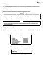
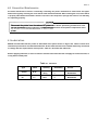
1.1
Scope
These specifications apply to the EPSON FX-87WI 170 dot matrix Printer.
1.1.1 Features
●
Upward compatibility with the FX-850(+)/1050(+), FX-800/1000, FX-86e/286e
●
380 cps (high-speed draft for both 80 and 136-column models)
●
285 cps (draft pica), 342 CPS (draft elite)
●
Advanced paper handling
Continuous paper
-3 paths for insertion (front/bottom/rear)
- Dual paper park and auto load (front/rear)
- The standard tractor unit can be set to 3 positions (2 push and 1 pull)
- Continuous paper can be used without removing the cut-sheet feeder (CSF)
Cut sheets
-2 paths for insertion (top/optional front)
- Auto loading
●
24K byte input buffer
●
16 character tables are supported for European model.
●
(Italic, pC437, 850,860,863,865, 437 Greek, 851,869,852,853,857, 855,866, GOST, 861)
6 character tables are supported for Non-European model.
●
(Italic, pC437, 850,860,863, 865)
Default setting mode replaces DIP switches.
●
Type B optional l/F boards can be installed.
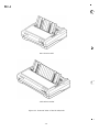
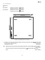
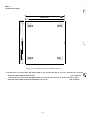
Figure 1-1 shows an exterior view of the FX-870/l 170.
1-1
.
REV.-A
4%
~
.-
r~..
...
“
80-column model
136-column model
Figure 1-1. External View of the FX-870/1170
.
1-2
,.
REV.-A
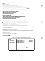
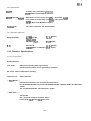
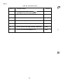
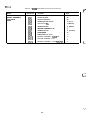
1.1.2 Options
C806372 (other)
Plain cut sheet feeder ( 80-column)
Plain cut sheet feeder ( 80-column)
C806391 (U.S. version)
Plain cut sheet feeder (136-column)
C806392 (other)
Plain cut sheet feeder (136-column)
C806381 (U.S. version)
Cut sheet feeder ( 80-column)
C806382 (other)
Cut sheet feeder ( 80-column)
C806401 (U.S. version)
Cut sheet feeder (136-column)
C806402 (other)
Cut sheet feeder (136-column)
C800201 (U.S. version)
Tractor unit ( 80-column)
C800202 (other)
Tractor unit ( 80-column)
C800211 (U.S. version)
Tractor unit (136-column)
C800212 (other)
Tractor unit (136-column)
C814001
Front sheet guide ( 80-column)
C814011
Front sheet guide (136-column)
C82305 (inch screw)
Serial l/F card
C82306 (mm screw)
Serial l/F card
C82307 (inch screw)
32KB intelligent serial l/F card
C82308 (mm screw)
32KB intelligent serial l/F card
C8231O (inch screw)
32KB intelligent parallel l/F card
C82311 (mm screw)
32KB intelligent parallel l/F card
C82313
32KB IEEE-488 l/F card
#8750
Fabric ribbon cartridge ( 80-column)
#8755(M)
Fabric ribbon cartridge (136-column)
#8758
Fabric ribbon sub cartridge
#8310
Roll paper holder (only for 80-column model)
C806371 (U.S. version)
1-3
REV.-A
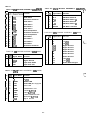
1.2 Specifications
1.2.1 Hardware Specifications
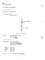
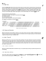
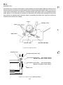
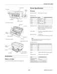
1.2.1.1 Printing Method
Printing method:
Impact dot matrix
Pin configuration: 9 wires
(diameter 0.29 mm)
wire
2+--- - 3
‘
9
$
-------
0.35mm (lf12”)
9&
Figure 1-2. Pin Configuration
Dot matrix:
9 x 7 matrix (high-speed draft)
9 x 9 matrix (draft)
.=.
18x 23 matrix (NLQ)
{....;’
1.2.1.2 Paper Handling
Feeding method:
Friction feed (front/top)
Push tractor feed (frontfrear)
Pull tractor feed (front./rear/bottom)
Push-pull tractor feed (front/rear)
Fanfold:
Tractor feed
Cut sheet:
Friction feed
Envelope:
Friction feed
Label:
Tractor feed
Roll:
Friction feed
Line spacing:
1/6”, 1/8”, or programmable (min.1/216”)
1-4
!..,
REV.-A
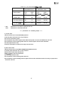
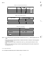
Table 1-1. Line Feed Speed(1 iine = 1/6”)
Continuous feed
Intermittent feed
* Thin:
Thick:
Thin
Thick
Thin
Thick
ms
ms
ms (ips)
ms (ips)
Fanfold paper
77
85
55 (3.0)
66 (2.5)
Cut sheet (manual)
69
77
45 (3.7)
55 (3.0)
Cut sheet (CSF)
71
77
48 (3.5)
55 (3.0)
Type of paper
Thickness is less than or equal to 0.18 mm.
Thickness is more than 0.18 mm.
***** precautions for Handling Paper *****
1 ) Friction feed
●
Set the release lever to the FRICTION position.
●
Load the paper from the front or top entrance.
●
Do not use continuous paper.
●
Do not perform any reverse paper feeds within the top 8.5 m m area and bottom 22 mm area.
●
Do not perform reverse feeds greater than 1/6” after the paper end has been detected.
●
Use the paper-tension unit.
●
Insert the multi-part cut sheet forms only from the front.
2) Push tractor feed
●
Set the release lever to the REAR PUSH/FRONT PUSH position.
●
Load the paper from the rear or front entrance.
●
Release the friction feed mechanism.
●
M u Iti-part paper must be carbonless.
●
Use the paper-tension unit.
●
Do not perform reverse feeds greater than 1/6”.
●
Do not perform reverse feeding after the paper end has been detected, because accuracy of paper feed
cannot be assured.
1-5
REV.-A
3) Pull tractor feed
●
Set the release lever to the PULL position.
●
Load the paper from the front, rear, or bottom entrance.
●
Release the friction feed mechanism.
●
Remove the paper-tension unit and attach the pull tractor unit.
(The front or bottom entrance is recommended for thick paper or labels.)
●
Insert the paper from either front or bottom.
Multi-part paper must be carbonless.
●
Do not perform reverse feeds.
●
4) Push-pull tractor feed
●
Set the release lever to the REAR PUSH/FRONT PUSH position.
●
Load the paper from the front or rear entrance.
●
Release the friction feed mechanism.
●
Remove the paper-tension unit and attach the pull tractor unit.
c Remove any slack in the paper between the platen and the pull tractor.
s Precisely adjust the horizontal position of the pull tractor and push tractor.
●
Multi-part paper must be carbonless.
●
Do not perform reverse feeds greater than 1/6”.
●
Do not perform reverse feeds after the paper end has been detected.
1.2.1.3 Paper Specifications
See Tables 1-2, 1-3, 1-4, 1-5, 1-6, and 1-7.
Recycled paper, envelopes, and labels require the following environmental conditions.
Normal environment
Temperature: 15-25 deg. C (59-68 deg. F)
Humidity: 30-60
?!.
RH
Table 1-2. Specifications for Cut Sheets (Plain Paper)
... ~.
●
Width
top insertion
front insertion
148-257 mm (5.8-10.1”)
80-column
148-420 mm (5.8-16.5”)
136-column
182-257 mm (7.2-10.1”)
80-column
182-364 mm (7.2-14.3”)
136-column
Length
Up to 364 mm (14.3”)
Thickness
0.065-0.14 mm (0.0025-0.0055”)
Weight
14-24 lb (45-78 Kg) (52.3-90 g/m2)
Quality
Plain paper
Recycled paper (in normal environment)
1-6
“-
REV.-A
- . . - . - .,. . . , nm . ——
m, -—
m—--i
1 ame 1-s. specmcawons lor uu~ mee~s [eamomess uupncamng raper]
-A -,-
- —A—
,-—
..L . -.
R-
--–
A,.- —
Width
front insertion
Length
182-257 mm (7.2-10.1”)
182-364 mm (7.2-14.3”)
80-column
136-column
Up to 297 mm (1 1.7”)
80-column
Up to 364 mm (14.3”)
136-column
Carbonless duplicating paper
Quality
Thickness
0.12-0.22 mm (0.0047-0.0086”)
Weight
12-15 lb (34-50 kg) (40-58 g/m2) - each
Copies
4 sheets (1 original + 3 copies) maximum
Table 1-4. Specifications for Continuous Paper
Width
101-254 mm (4-10”)
80-column
101-406 mm (4-16”)
136-column
Thickness
0.065-0.32 mm (0.0025-0.012”)
Weight
14-22 lb (45-70 kg) (52.3-82 g/m2) - single sheet
12-15 lb (34-50 kg) (40-58.2 g/m2) - each
Quality
Plain or carbonless duplicating paper
Recycled paper (in normal environment)
(with push tractor and optional pull tractor)
Copies
4 sheets (1 original + 3 copies) maximum
Table 1-5. Specifications for Envelopes
Size
No. 6
166 mm x 92 mm
No. 10
240 mm x 104 mm
Thickness
0.16-0.52 mm (0.0063-0.0197”)
* Differences in thickness within the printing area
must be less than 0.25 mm (0.0098”).
Weight
12-24 lb (39-78 kg) (45-91 g/m2)
Quality
Bond paper, plain paper, airmail
Notes: 1) Envelopes must be inserted from the top.
2) Keep the longer side of the envelope horizontal during insertion.
3) Set the left edge of a No. 6 envelope at the sheet guide setting mark.
4) Do not feed envelopes with the cut sheet feeder.
1-7
.
REV.-A
Table 1-6. Specifications for Labels
Size
C.
“:%
t.
2 1/2” X 15/16”
4“ X 15/16”
4“ X 17/16”
Thickness
0.07-0.09 mm (0.0028-0.0031”) - base paper
0.16-0.19 mm (0.0063-0.0075”) - total
Quality
Plain paper
Notes: 1) Labels must be fanfold.
AVERY CONTINUOUS FORM IABELS
2) Example of labels
AVERY MINI-LINE LABELS
3) Labels should be used with the pull tractor (front, bottom), or with the front push tractor.
4) Do not perform reverse feed at any time. (including by hand).
5) Remove labels from the paper path when not in use.
z
i .3.,
Table 1-7. Specifications for Roll Paper
Size
216 +/- 3 mm (8.5 +/- 0.12”)
Thickness
0.07-0.09 mm (0.0028-0.0035”)
Weight
14-22 lb (45-70 Kg) (52.3-82 g/m2)
Quality
Plain paper
Note: Roll paper isavailable only forthe 80-column model optionally, and itsdiameter must notexceed 127
mm (5”).
.%,,.,
[“,: ,.
. . ,.
1-8
REV.-A
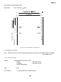
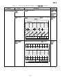
1.2.1.4 Printable Area
1) Cut sheets
top insertion
148-257 mm (5.8-10.1”): 80 columns
148-420 mm (5.8-16.5”) : 136 columns
front insertion
182-257 mm (7.2-10.1”): 80 columns
182-364 mm (7.2-14.3”): 136 columns
>
<
●1
<
L
*1
Printable Area
1.
T“
I_
~ ABCD
WXYZ
I ABCD
WXYZ
-1-
Figure 1-3. Printable Area for Cut Sheets
* 1 3.0 mm (0.1 2“) or more when the paper width is less than 364 mm (14.3”). 25 mm (0.9”) or more when
(136-column)
the paper width is 420 mm (16.5”).
( 80-column)
3.0 mm (0.12”) or more.
Note:
Paper feed accuracy cannot be assured within 24 mm (0.94”) from the bottom edge of the paper.
(top insertion)
Paper feed accuracy cannot be assured within 48.5 mm (1.9”) from the bottom edge of the
(front insertion)
paper.
1-9
REV.-A
2) Continuous paper
<
* 1
<
A.
Printable Area
*1,
>
L \
i
ABCD
WXYZ
t
I_
4--
ABCD
WXYZ
4
Figure 1-4. Printable Area for Continuous Paper
*1 13 mm (0.51”) or more when the paper width is 101 mm to 241 mm (4” to 9.5”). 25 mm (1.0”) or more ~~.
when the paper width is 254 mm (10”).
( 80 columns) . .1 .
13 mm (0.51”) or more when the paper width is 101 mm to 377.8 mm (4” to 14.87”). 25 mm or more
when the paper width is 381 mm to 406 mm (15” to 16”).
1-1o
(136 columns)
REV.-A
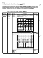
3) Roll paper (80-column model only)
top insertion
216 +/- 3 mm (8.5 +/- 0.12”)
101-254 mm (4-10”): 80 columns
101-406 mm (4-16”): 136 columns
k
>
+1
●1
Printable Area
+
o
0
0
0
0
0
0
0
0
, 0
4o
WXYZ
0
0
.--0.
%
u
.
WXYZ
. . ABCD
o
0
0
0
0
0
0
0
0
0
Figure 1-5. Printable Area for Roll Paper
*1 3.0 mm (0.1 2“) or more
Note:
Paper feed accuracy cannot be assured within 24 mm (0.94”) from the bottom edge of the paper.
(top insertion only)
1.2.1.5 Ribbon Cartridge
Ribbon
Cartridge type (same as FX series)
# 8750
- 80-column model
# 8755(M)
- 136-column model
# 8758- Subcartridge
Color
Black
Life of ribbon
3 x 10⁶ characters (at 14 dots/character)
1-11
.
REV.-A
.c-.. .
.,
1.2.1.6 Electrical Specifications
See Table 1-8 and 1-9.
Table 1-8. Electrical Specifications for 120V Model
Rated voltage
120 VAC
Input voltage range
103.5-132 V AC
Rated frequency range
50-60 Hz
Input frequency range
49.5-60.5 Hz
Rated current
1.8 A
Power consumption
Approx. 45 W ( 80 columns)
Approx. 45 W (136 columns)
(Self test in draft mode, 10 cpi)
1.0 kVAC, 1 second
Dielectric strength
(Between AC line and chassis)
Table 1-9. Electrical Specifications for 220/240V Model
Rated voltage
220-240 VAC
Input voltage range
198-264 VAC
Rated frequency range
Input frequency range
50-60 Hz
49.5-60.5 Hz
Rated current
0.9 A
Power consumption
Approx. 45 W ( 80 columns)
Approx. 45 W (136 columns)
(Self test in draft mode, 10 cpi)
1.5 kVAC, 1 second
Dielectric strength
(Between AC line and chassis)
f“.,
1.2.1.7 Environmental Conditions
Table 1-10. Environmental Conditions
Temperature
5 to 35 deg.C (41 to 95 deg. F) — operating
-30 to 60 deg.C (-22 to 140 deg. F) — in shipment container
Humidity
10 to 80
5 to 85
Resistance to shock
‘Y.
Y.
RH — operating
RH — non-operating
IG, within 1 ms — operating
2G, within 1 ms — non-operating
Resistance to vibration
0.25G, 55 Hz max. — operating
0.50G, 55 Hz max. — non-operating
1-12
REV.-A
1.2.1.8 Reliability
5 million lines (excluding a printhead)
MCBF
(MCBF: Mean Cycles Between Failures)
MTBF (expected value)
4000 power on hours (duty cycle 25Yo) — 80-column model
6000 power on hours (duty cycle 25Yo) —136-column model
(MTBF : Mean Time Between Failures)
100 million characters (14 dots/character)
Printhead Life
1.2.1.9 Safety Approvals
(U.S.A model)
UL1950 with D3
Safety standards
CSA22.2#220
R.F.I
EN 60950 (TUV)
(EUR model)
FCC class B
(U.S.A model)
VDE0871 (Self certification) (EUR model)
1.2.2 Firmware Specifications
1.2.2.1 Print Control
Printing direction
Text mode
Bidirectional printing with logic seeking.
(Unidirectional printing can be specified by software.)
Bit image mode Unidirectional printing
Character sets
ASCII characters
— ESC/P mode —
International characters (13 countries) and their italics
PC 437,850,860,863,865, 437 Greek, 851,869,852,853,857, 855,866, GOST, 861 (European
model)
PC 437,850,860,863,865 (Non-European model)
— IBM mode —
PC 473,865
(PC = Personal Computer character table )
Fonts: Draft, NLQ Roman, NLQ Saris serif
1-13
.
REV.-A
f’:.
.,’;:
Table 1-11. Character Size and Pitch
I
Type
of
letters
I Width I
Height
[mm]
I
I
.,.-
Character
pitch
[mm]
[mm]
2.54 (10 cpi)
Pica
2.1
3.1
Condensed
1.05
3.1
1.48 (17 cpi)
Elite
1.7
3.1
2.11 (12 cpi)
Condensed
elite
\
I
0.85
3.1
I
1.27 (20 cpi)
Table 1-12. Printable Columns
Type of letters
Printable columns [cpl]
80-column model
136-column model
I
Pica
I
80
I
136
I
I
Condensed
I
137
I
233
I
Elite
Condensed elite
96
163
160
272
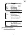
Table 1-13. Print Speed
Type of letters
I
High-speed draft
Print speed [cm]
380
Draft pica
285
(320) [1421
[142]
Draft elite
342
[170]
Condensed draft pica
243
[122]
142
[ 711
Emphasized draft pica
tI
I
NLQ normal pica
57
I
1
I
Notes: 1) The printing speed for high speed draft is reduced to the value in “( )“ with thick paper (over 0.18
mm).
2) The printing speed for high speed draft is reduced to the value of “draft pica” when any graphic
character is in the line.
3) The printing speed for draft is reduced to the value in “[ ]“ when any italic character is in the
line.
4) The speed for high duty printing is reduced to approximately half of each speed, except for the
printing speed in “[ l“.
1.2.2.2 Input Data Buffer
24K or OK bytes (selectable with power on default settings; see Section 1.5.2. )
1-14
REV.-A
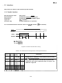
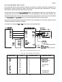
, 1.3 Interface
This printer has a built-in, 8-bit centronics parallel interface.
1.3.1 Parallel Interface
Data transmission mode
Synchronization
8-bit parallel
Controlled by external STROBE pulse.
Handshaking
Controlled by ACKNLG and BUSY signals.
Logic level
ITL- compatible
Connector plug
57-30360 (Amphenol) or equivalent
It is recommended that the interface cable be as short as possible (10 feet maximum).
DATA
:. . . . . . . . . . . . . . . . . . . . . . . . . . . . . . . . . .
STROBE
tl
tl
t2
tl
t3
tl : 0.5 us (min.)
t2: 7 us (approx.)
t3: 5 us (approx.)
Figure 1-6. Data Transmission Timing
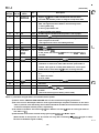
Table 1-14. Connector Pin Assignments and Signal Functions
Signal
Return
Pin No. Pin No.
1
19
Signal
Name
STROBE
Description
Dir.
In
STROBE pulse to read data in. Pulse width must be more than
0.5 Bs at receiving terminal.
2
20
DATA 1
In
3
21
DATA 2
In
respectively. Each signal is HIGH when data is a logical 1 and
LOW when a logical O.
4
22
DATA 3
In
5
23
DATA 4
In
6
24
DATA 5
In
7
25
DATA 6
In
26
DATA 7
In
8
These signals represent the 1st to 8th bits of parallel data,
1-15
.
REV.-A
(Continued)
Signal
Signal
Pin No.
Return
Pin No.
10
28
ACKNLG
out
Approx.12 us pulse. LOW indicates that data has been
BUSY
out
A HIGH signal indicates that the printer cannot receive more
Description
Dir.
Name
e. .- . . ,
received and that the printer is ready to accept more data.
11
29
data. The signal becomes HIGH in the following cases:
1. During data entry
2. During input buffer full
3. During printer error status
PE
12
30
13
—
—
out
—
14
—
AUTO FEED
In
A HIGH signal indicates that the printer is out of paper.
Pulled up to +5V through a 3.3 K-ohm resistor.
When this signal is LOW, paper is automatically fed one line
upon receipt of a CR code.
XT
15
—
NC
—
(The signal level can be set LOW by default.)
Not used.
Logic GND level.
Printer chassis GND.
16
—
Ov
—
17
—
CHASSIS
—
~~.
In the printer, the chassis GND and the logic GND are short-
GND
circuited.
Not used.
18
—
NC
—
9 to 30
—
—
TWISTED-PAIR RETURN signal GND level.
31
—
GND
INIT
In
When the level of this signal becomes LOW, the printer
controller is reset to its initial state and the print buffer is
cleared. This signal is normally atthe HIGH level, and its pulse
width must be more than 50 ps at the receiving terminal.
32
—
ERROR
out
The level of this signal becomes LOW when the printer is
in —
1. Paper-out status
2. Error status
33
34
—
—
35
—
36
—
GND
NC
—
SLCT IN
—
TWISTED-PAIR RETURN signal GND level.
—
Not used.
—
Pulled up to +5V through a 3.3 K-ohm resistor.
In
The data between DC3 and DCI is invalid when this signal
{.
-=
. ‘.
is HIGH.
(The level of this signal is factory set to LOW.)
Notes: 1 ) Direction of signal flow is as viewed from the printer.
2) Return means TWISTED PAIR RETURN and is to be connected at signal ground level.
3) Be sure to use a twisted-pair cable for each signal and always complete connection on the return
side. To prevent noise effectively, these cables should be shielded and connected to the chassis
of the host computer and the printer, respectively.
4) All interface conditions are based on ITL level. Both the rise and fall times of each signal must be
less than 0.2 VS.
5) Data transfer must not be carried out by ignoring the ACKNLG or BUSY signal.
(Data transfer to this printer can be carried out only after confirming the ACKNLG signal or when .
.
:_ .,.
the level of the BUSY signal is LOW.)
1-16
REV.-A
, 1.3.2 Optional Interface
The following interface cards can be used for this printer.
Table 1-15. Optional Interface
Type
Catalog #
C82305* (inch screw)
Serial I/F card
C82306* (inch screw)
Serial l/F card
C82307* (inch screw)
32KB intelligent serial l/F card
C82308* (inch screw)
32KB intelligent serial l/F card
C8231O* (inch screw)
32KB intelligent parallel l/F card
C82312* (inch screw)
32KB intelligent parallel l/F card
C82313* (inch screw)
Local Talk l/F card card
C82314* (inch screw)
Coax l/F card
C82315* (inch screw)
Twinax l/F card
Note: The last digit of catalog # “*” varies depending on the country.
1.4 Control Panel
1.4.1 Components
Figure 1-7. Control Panel
Buttons
OPERATE
PAUSE/TEAR OFF
PAPER FEED
FONT
1 lock type button
l - - (non-lock Push type buttons)
J
Indicators
3 LEDs
READY — (green)
FONT (Draft, Roman, Saris serif) — (green)
CONDENSED — (green)
1-17
.
REV.-A
,:.,
(-.
1.4.2 Buttons
[PAUSEI
Selects printing or pause alternately when there is some data to print in the input buffer.
Advances continuous paper to tear-off position when the printer has printed all received data and is ready
to receive more print data.
[PAPER FEEDI
Advances the paper line by line using the current line spacing setting while the printer is ready to print or
paused by PAUSE button.
Holding down the button for about 1 second, it advances the paper to the next top-of-form (TOF) position.
*
Loads continuous paper inserted in the push tractor or cut sheets in the CSF when the printer has detected ‘“’
a paper out.
[FONT]
Selects NLQ Roman, NLQ Saris serif, Draft, and condensed of those 3 fonts in rotation:
(Draft~Draft cond.~ Roman~ Roman cond.~ Sans.~ Saris. cond.~ Draft ~Draft cond. ....)
(The factory setting k the Draft, uncondensed font)
The selection is executed when the button is released.
The selection is stored in non-volatile memory.
Enables the micro feed function when pressed along the PAUSE or PAPER FEED button. The micro
feed function is described below.
~.. . . .
: . . .. .
FONTI+[PAUSEI or IFONTI+[PAPER FEEDI
Activates the function. The PAUSE and PAPER FEED buttons micro-adjust the paper position up or down,
as described below:
[FONT]+ [PAUSE]
1-18
REV.-A
Advances the paper forward by 1/108 inch per step.
IFONTl+[pApER
FEEDI
Moves the paper backward by 1/108 inch per step.
Pressing FONT along with PAUSE or PAPER FEED lets you micro-adjust the following positions:
●
the loading position, immediately after paper is loaded in the printer.
●
the tear-off position, when paper has been advanced for tear off.
●
the current print position.
The adjusted loading and tear-off positions will be stored in non-volatile memory (except for the loading
position of cut sheets by manual insertion).
You can end micro feed (or micro adjust) mode by pressing the FONT button again. The printer exits this mode
automatically in several seconds if no operation is performed.
Pressing FONT+ PAUSE or FONT+ PAPER FEED switches bins when a double-bin CSF is installed, there is no
paper in the paper path, and friction feed is selected.
IFONTl+[pApER FEED]
Ejects a cut sheet forward or feeds continuous paper backward to the paper park position.
1.4.3 Indicators
<READY>
Ready to print :
ON
Tear-off :
Blinking
(ls~o
duty)
Pause :
Blinking (50% duty)
Paper error :
Blinking (25’Yo duty)
Head hot :
Blinking (25Y0 duty)
<FONT>
Draft :
OFF
NLQ Roman :
ON
NLQ Saris serif:
Blinking
<CONDENSED>
Normal pitch :
OFF
Condensed pitch : ON
When an error occurs, the READY, FONT, and CONDENSED LEDs will be used in combination to identify the
error.
All indicators blink simultaneously: Fatal error
All indicators blink sequentially in the clockwise direction: Voltage error
1-19
REV.-A
1.5
c
.!.
,,. ,
Functions
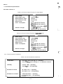
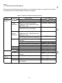
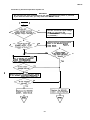
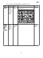
1.5.1 Default Settings
Users can set certain default parameters, which will be used at printer initialization.
To change the parameters shown in Table 1-16, Group 1 Features, follow the steps below.
1. Turn on the printer while pressing the FONT button. Then, the current default settings will be printed on
the paper loaded in the paper path.
2. Press the FONT button to select a parameter. The FONT and CONDENSED LEDs turn on, off, or blink to
show the current parameter selected. Press the FONT button as many times as necessary to make the
LEDs indicate the setting you want. (See Table 1-16.)
3. Press the PAUSE button to change the setting. The READY LED shows your selection.
4. Repeat this procedure for any Group 1 feature you want to change. (After you have set the feature at the
bottom of Table 1-16, the printer returns to the first feature in Table 1-16.)
5. When all the settings are as you want them, turn off the printer. The settings will be stored in non-volatile
memory.
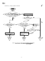
To change the settings shown in Table 1-17, Group 2 Features (ESC/P mode), or in Table 1-18, Group 2 Features
(IBM mode), follow the steps below.
1. Turn on the printer while pressing the FONT and PAUSE buttons. Then, the current CG table for either
ESC/P or IBM mode will be printed on the paper loaded in the paper path.
2. Press the FONT button to select the character table. The FONT, CONDENSED, and READY LEDs turn on,
off, or blink to show your selection. Press the FONT button as many times as necessary until the FONT,
CONDENSED, and READY LEDs indicate the character set you want.
3. Turn off the printer. The settings will be stored in non-volatile memory.
1-20
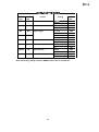
REV.-A
I ault$ I - Iu. -g uup m rcacul ca
FONT
COND.
LED
LED
OFF
ON
OFF
BLINKS
ON
OFF
ON
ON
ON
BLINKS
BLINKS
OFF
BLINKS
ON
BLINKS
BLINKS
Setting
Feature
READY
LED
ESC/P
Emulation
OFF
IBM Proprinter
ON
Pica
OFF
Elite
ON
11 inch
OFF
12 inch
ON
8.5 inch
OFF
70/6 inch (A4)
ON
No skip
OFF
Skip 1 inch
ON
o
OFF
0
ON
Auto tear-off
Valid
OFF
Invalid
ON
Auto LF with CR
Depends on l/F
OFF
Valid
ON
Character pitch
Page length
Skip over perforation
Zero face
Note: The factory setting is that the READY LED is OFF for all features.
1-21
REV.-A
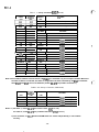
Table 1
FONT
I
I
LED
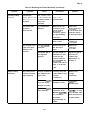
7. Group 2 Features (ESC/P Mode)
COND.
READY
LED
LED
CG table
U. S. A.(std. setting)
Italic
ON
France
BLINKS
I
OFF
OFF
I
ON
ON
OFF
ON
Germany
I
U.K.
Denmark
BLINKS I
OFF
ON
OFF
BLINKS
OFF
Sweden
OFF
BLINKS
ON
Italy
OFF
BLINKS
BLINKS
ON
OFF
OFF
ON
ON
OFF
OFF
BLINKS
PC860
ON
ON
OFF
PC863
ON
ON
ON
PC865
Spain
Character table PC437
PC850
ON
PC437 Greek
BLINKS I
I
ON
BLINKS
OFF
PC851
ON
BLINKS
ON
PC869
ON
BLINKS
BLINKS
PC852
I
BLINKS
I
BLINKS
t
BLINKS
BLINKS
I
OFF
I
I
OFF
OFF
ON
OFF
I
PC853
ON
I
PC857
BLINKS I
PC855
OFF
PC866
BLINKS
ON
ON
GOST
BLINKS
ON
BLINKS
PC861
Note: The CG tables between ‘PC437 Greek’ and ‘PC861’ are available only for European models. When the
CG table of PCXXX is selected, the table is assigned as the table selected by the ESC tl command.
Then ESC tl and ESC 6 are set as defaults. (Codes 80-9FH are printable characters.)
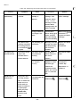
Table 1-18. Group 2 Features (IBM Mode)
FONT
COND.
READY
LED
LED
LED
OFF
OFF
ON
OFF
OFF
BLINKS
PC437 (table 2)
OFF
ON
OFF
PC865 (table 1)
OFF
ON
ON
PC865 (table 2)
CG table
Character table PC437 (table 1) (std.)
Notes: 1) For table 1, codes 80-9FH are control codes. (ESC 7 is set.)
For table 2, codes 80-9FH are printable characters. (ESC 6 is set. )
2) The CG tables for ESC/P mode and IBM mode are saved independently in non-volatile
memory.
1-22
,.
+
..
REV.-A
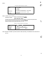
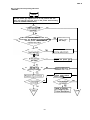
1.5.2 Power On Default Settings
The printer also lets you change some of its power on parameters. To change the settings shown in Table 119, Group 3 Features (Power on settings), follow the steps below.
1. Turn on the printer while pressing the PAUSE, PAPER FEED, and FONT buttons.
2. Press the button indicated in Table 1-19 for a few seconds to change parameters.
Table 1-19. Group 3 Features (Power-on Settings)
Button
Setting
Feature
valid (**) or invalid (*)
[PAUSE]
Input buffer
[PAPER FEEDI
[FONT]
Draft printing speed
high (**) or normal (*)
Auto CR
valid (**) or invalid (*)
standard setting
Notes: 1) Auto CR moves the next print position to the left margin when LF or ESC J code is sent.
2) ‘*’ is one beep, and ‘**’ is two beeps.
If no operation is executed within a few seconds, the printer exits the power on selection mode with
five beeps (*****).
The selected value is stored in non-volatile memory.
* The printer automatically becomes ready to print after the selection.
1.5.3 Buffer-full Printing
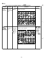
1.5.4 Hexadecimal Dump
Press the PAUSE button while turning on the printer to put the printer in hexadecimal dump mode. In this
mode, received data is printed out in hexadecimal format, along with the corresponding ASCII characters.
This function is useful to check received data from the host. If a received code is not a printable ASCll character,
the printer prints a period (.) in the ASCII column.
Figure 1-8. Hexadecimal Dump Printout
1-23
REV.-A
1.5.5 Self Test
Press the PAPER FEED button while turning on the printer to put the printer in self-test mode. To stop the self
test, turn off the printer. (The control panel is still operational in self-test mode for paper handling and font
selection. ) When pages are printed from the CSF, the first sheet is used for scaling the sheet length. Then,
the maximum number of printable lines is printed in the bottom line of the sheet and saved in non-volatile
memory as the default page length. Page lengths are saved individually when a dual bin CSF is in use.
The self test prints out the following:
(a) Maximum printable lines (only on cut sheets from the CSF)
(b) Firmware version
(c) Current default settings
(d) Short help messages for control panel operation
(e) A Pattern of characters, as shown below.
Figure 1-9. Self Test Printout
1.5.6 Paper-out Detection
When the paper-out sensor detects a paper out, the printer enters the pause condition automatically after
feeding or printing several lines. When a paper-out is detected, load new paper properly and set the printer
ready to print by pressing the PAUSE button.
1.5.7 Auto
Tear-off
a.,
{>,., ..-”“
When the release lever is set to one of the tractor positions, the paper advances to the tear-off position
automatically if the input data buffer is empty and the paper is at the top-of-form position (If the printer
receives no additional data after it has received a form feed). If subsequent data is sent to the printer, the paper
reverse feeds to the original position automatically and the printing starts. This function can be turned off in
the default setting mode.
1.5.8 Thermal Protection
When the printhead temperature exceeds 82 deg. C, the printer stops printing to protect the printer from
overheating.
1.5.9 High Duty Printing
The printer stops printing when the printing duty is too heavy for the printer’s power supply. If it occurs, the :“
.
printer continues printing the rest at half speed.
1-24
REV.-A
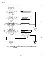
, 1.5.10 Sheet Loading and Sheet Ejection
The release lever engages or disengages the push-tractor unit drive mechanism. The lever’s operation
provides with improved paper-handling functions:
(a) Automatic cut sheet loading without the cut sheet feeder
Move the release Ievertothe FRICTION position and load a sheet using the paper guide (top or optional front).
A few seconds later, the sheet is automatically loaded to the top-of-form position, and the printer becomes
ready to print.
(b) Automatic cut sheet loading and ejection with the cut sheet feeder
Move the release lever to the FRICTION position and load a stack of paper into the hopper of the cut sheet
feeder. Pressing the PAPER FEED button loads the sheet to the top-of-form position. If a paper-out is detected
before printing starts, the sheet is automatically loaded to the top-of-form position, without the PAPER FEED
button being pressed.
(c) Continuous paper loading and ejection (paper park)
Move the release lever to REAR PUSH/FRONT PUSH position and load the paper into the tractor unit. Press
the PAPER FEED button to load the paper automatically to the top-of-form position. If a paper-out is detected
before printing starts, the paper is automatically loaded to the top-of-form position, without the PAPER FEED
button being pressed.
If the FONT+ PAPER FEED buttons are pressed when the continuous paper is loaded, the paper is ejected
backward to the paper park position. To feed several pages backward, repeat this operation several times.
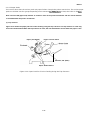
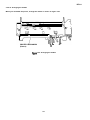
1.5.11 Adjust Lever Operation
The platen gap adjust lever must be set to the proper position (from the 8 step available) for the paper
thickness.lf this lever is set to the position 2 (4th step) or higher, printing speed and paper feeding speed will
be reduced.
Table 1-20. Lever Positions
I
I
Lever position
Paper thickness
O (2nd step)
0.06-0.12 mm
1 (3rd step)
0.13-0.17 mm
2 (4th step)
3 (5th step)
0.18-0.25 mm
I
I
0.26-0.32 mm
Note: If printing density becomes lighter, move the platen gap adjust lever position one step closer.
1-25
REV.-A
Position 1
(3rd step)
$\ \
..
-=.
&’”
r’
Platen Gap Adjust Lever
4.-
Q
Figure 1-10. Lever Positions
1.5.12 Printer Initialization
The printer is initialized in the following cases.
(1) When the printer is turned on.
(2) When the INIT signal or CMREQ (optional l/F ) is input.
When the printer is initialized, it performs the following functions:
●
The printhead returns to the leftmost position (carriage home).
●
The READY LED lights.
●
The printer clears the print buffer and input data buffer.
●
The line spacing is set to 1/6 inch.
●
The page length and skip over perforation settings are returned to their default values.
●
All vertical tab positions are cleared.
●
The horizontal tab positions are set to every 8 columns.
●
The print mode is set to the default value set from the control paneI and stored in non-volatile memory.
TOF position will be reset in the following cases.
(1) Power on
(2) INIT signal or CMREQ (optional I/F)
(3) Sofiware reSet command (ESC @)
(4) Page length command (ESC C)
NOTE: The CMREQ signal goes Low when the command request is sent from the optional card to the main
system.
1-26
REV.-A
1.5.13 Buzzer
The buzzer beeps for 0.1 second at a time. These beep sounds a recombined in various ways, as shown below,
to indicate different meanings.
In the following table, each “*” stands for one beep.
Table 1-21. Buzzer Functions
Sound and Description
Status
BEL code
*
Carriage trouble
Sounds when a BEL code has been input.
*** ***
An error has occurred with the carriage position.
Voltage error
No beeps.
Fatal error
(Shown by indicators blinking sequentially in the clockwise direction.)
No beeps.
Incorrect memory
(Shown by indicators blinking simultaneously.)
** ** ** **
— RAM
** ** ** ** **
Paper error
— E2PROM
**** **** **** **** ****
Continuous paper has run out.
Cut sheet paper from the CSF has run out.
No paper was present at the start of a self test.
A sheet could not be ejected from the CSF.
***
Other paper detection error have occurred.
With single sheet feed selected, no paper is present.
Continuous paper can’t be loaded.
Illegal paper
Paper runs out after the PAPER FEED button has been messed.
***** ***** *****... (continuously till corrected)
release/u nrelease
The release lever has been changed while there was paper in the paper
path.
Recognition of
Change the lever again or remove the paper in the path to stop the sound.
*
operation
Power-on operation (self test, hex dump, default setting, power-on
selection)
CSF bin-1 selected.
**
Micro feed
CSF bin-2 selected.
*
The adjusted value set using micro feed is the same as the factory setting
value (loading position or tear-off position).
***** ***** *****... (continuously until button is released)
The micro feed value has reached its upper or lower limit.
1-27
.
REV.-A
..::,\
f’
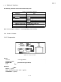
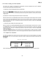
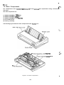
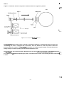
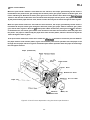
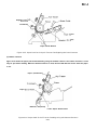
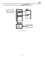
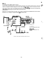
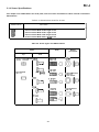
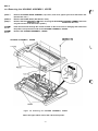
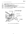
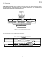
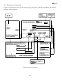
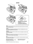
1.6 Main Components
The components of the FX-870/l 170 are designed for easy removal and replacement during maintenance
and repair.
The main components are:
(1) BOARD ASSEMBLY, C094 MAIN
(2) BOARD ASSEMBLY, C094 PNL
(3) BOARD ASSEMBLY, C076 PSB/PSE
(4) Printer Mechanism
(5) Housing Assembly
The following figure shows the main components of the FX-870/l 170.
Platen Ga
PSB/PSE
f-::
-..
”
y, C094 M AIN
Pril 7
Figure 1-11. Main Components
1-28
1
REV.-A
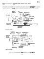
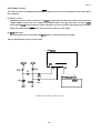
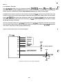
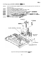
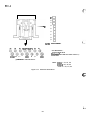
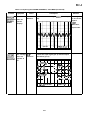
q.6.I
BOARD
ASSEMBLY, C094 MAIN (Main Control Circuit Board)
Basically, the same board layout is used in both the 136-column model and the 80-column model. The CPU
It consists of a TMP90C041F 8-bit CPU, an
on this board controls all the main functions of the printer.
E05A55YA gate array, an E2PROM, a PSRAM, a MASK ROM, motor drivers, and head drive transistors.
PF MOTOR
DRIVER
LPAI 476H
CPU
TM P90C041F
CENTRONICS l/F
CR MOTOR
o
~~~f~4M
~
E2PROM
~>
7
\
““
q
\ Ill \’
*PS RAM
1 Cl”lp
E
~
n
o
0
,,,,,
Q=
/
— — ——
4;~HEAD DRIVE
TRANSISTOR
.
.
I
~—
+7
”MASK
I
0
o
T
/
“
‘
OM
CN2 for OPTION IF
‘
GATE ARRAY
E05A66YA
<136-column model>
PF MOTOR
DRIVER
pPA1476H
CPU
TM P90C041F
CENTRONICS l/F
\//
r
CR MOTOR
g;!f;24M
r~;--o’”
\
–y
qE2pR0M
,PS RAM
E
ml
0
00
,(0
0:
n:
0’
I
~~
MASK ROM
CN2 for OPTION l/F
0
o
~
?r-
r
HEAD DRIVE
TRANSISTOR
‘~“
GATE ARRAY
E05A66YA
c80-column model>
Figure 1-12. BOARD ASSEMBLY, C094 MAIN (Main Control Circuit B-d
1-29
.
REV.-A
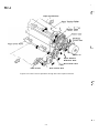
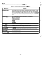
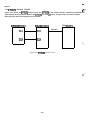
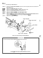
1.6.2 BOARD ASSEMBLY, C094 PNL (Control Panel Circuit Board)
K’.
*“
This board functions as the control panel of the FX-870/l 170, and consists of a power switch, three function
switches, and three indicator LEDs.
Figure 1-13. BOARD ASSEMBLY, C094 PNL (Control Panel Circuit Board)
1.6.3 BOARD ASSEMBLY, C076 PSB/PSE (Power Supply Circuit Board)
This board is composed of an input filter circuit, a transforming circuit, a switching regulator circuit, a
rectifying circuit, a smoothing circuit, and various protecting circuits.
,.~..
f..;
Figure 1-14. BOARD ASSEMBLY, C076 PSB/PSE (Power Supply Circuit Board)
1-30
REV.-A
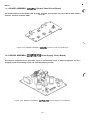
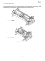
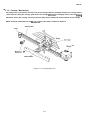
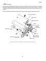
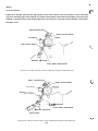
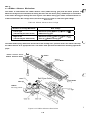
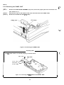
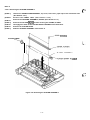
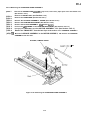
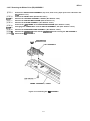
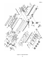
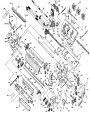
1.6.4 Printer Mechanism
The printer mechanism consists of a 9-pin impact dot head, a carriage mechanism, a carriage motor, a paPer
feed mechanism, a paper feed motor, a ribbon feed mechanism, and various sensors.
<136-column
<80-column model>
Figure 1-15. Printer Mechanism
1-31
.
REV.-A
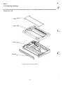
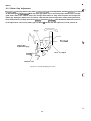
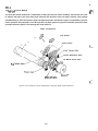
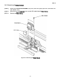
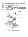
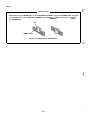
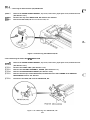
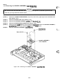
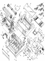
1.6.5 Housing Assembly
The printer mechanism and all the boards are contained in a housing assembly that consists of the uppercase
and the lower case.
Printe
Upper
L
Lower
.-,. .
{’:. :,;.
Front Co
Figure 1-16. Housing Assembly
1-32
REV.-A
CHAPTER 2
OPERATION PRINCIPLES
2-1
2.1 Printer Mechanism Operation . . . . . . . . . . . . . . . . . . . . . . . . . . . . . . . . . . . . . . . . . . . . . . . . . . . . . . . . . . . . . . . . . . . . . . . .
...
2.1.1 Printhead Mechanism . . . . . . . . . . . . . . . . . . . . . . . . . . . . . . . . . . . . . . . . . . . . . . . . . . . . . . . . . . . . . . . . . . . . . . 2-1
2-3
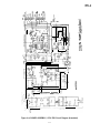
2.1.2 Carriage Mechanism. . . . . . . . . . . . . . . . . . . . . . . . . . . . . . . . . . . . . . . . . . . . . . . . . . . . . . . . . . . . . . . . . . . . . . . . . . .
...
2.1.3 Platen Gap Adjustment . . . . . . . . . . . . . . . . . . . . . . . . . . . . . . . . . . . . . . . . . . . . . . . . . . . . . . . . . . . . . . . . . . . 2-4
..
2.1.4 Paper Handling Mechanisms . . . . . . . . . . . . . . . . . . . . . . . . . . . . . . . . . . . . . . . . . . . . . . . . . . . . . . . . . . .2-5
2-5
2.1.4.1 Paper Feed Mechanisms . . . . . . . . . . . . . . . . . . . . . . . . . . . . . . . . . . . . . . . . . . . . . . . . . . . . . .
..
2.1.4.2 Paper Advance Mechanisms . . . . . . . . . . . . . . . . . . . . . . . . . . . . . . . . . . . . . . . . . . . . . . 2-6
...
2.1.4.3 Paper Paths . . . . . . . . . . . . . . . . . . . . . . . . . . . . . . . . . . . . . . . . . . . . . . . . . . . . . . . . . . . . . . . . . . . . . . . 2-13
..
2.1.4 Ribbon Advance Mechanism . . . . . . . . . . . . . . . . . . . . . . . . . . . . . . . . . . . . . . . . . . . . . . . . . . . . . . . . .2-18
2-19
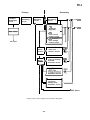
2.2 Power Supply Operation . . . . . . . . . . . . . . . . . . . . . . . . . . . . . . . . . . . . . . . . . . . . . . . . . . . . . . . . . . . . . . . . . . . . . . . . . . . . .
..
2.2.1 Power Supply Overview . . . . . . . . . . . . . . . . . . . . . . . . . . . . . . . . . . . . . . . . . . . . . . . . . . . . . . . . . . . . . . . .2-19
2-20
.
.
.
.
.
.
.
.
.
.
.
.
.
.
.
.
.
.
.
.
.
.
.
.
.
.
.
.
.
.
.
.
.
.
.
.
.
.
.
.
.
.
.
.
.
.
.
.
.
.
.
.
.
.
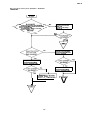
2.2.2 Power Supply Circuit Operation
...
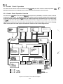
2.3 Control Circuit Operation . . . . . . . . . . . . . . . . . . . . . . . . . . . . . . . . . . . . . . . . . . . . . . . . . . . . . . . . . . . . . . . . . . . . . . . . . . 2-22
..
2.3.1 Control Circuit Operation Overview . . . . . . . . . . . . . . . . . . . . . . . . . . . . . . . . . . . . . . . . . . . . . 2-22
2-25
2.3.2 Reset Circuit . . . . . . . . . . . . . . . . . . . . . . . . . . . . . . . . . . . . . . . . . . . . . . . . . . . . . . . . . . . . . . . . . . . . . . . . . . . . . . . . . . . . . .
...
2.3.3 Sensor Circuits . . . . . . . . . . . . . . . . . . . . . . . . . . . . . . . . . . . . . . . . . . . . . . . . . . . . . . . . . . . . . . . . . . . . . . . . . . . . . . .2-26
..
2.3.4 Carriage Motor Drive Circuit . . . . . . . . . . . . . . . . . . . . . . . . . . . . . . . . . . . . . . . . . . . . . . . . . . . . . . . . . .2-27
..
2.3.5 Paper Feed Motor Drive Circuit . . . . . . . . . . . . . . . . . . . . . . . . . . . . . . . . . . . . . . . . . . . . . . . . . . . . . 2-28
2-23
2.3.6 Printhead Drive Circuit . . . . . . . . . . . . . . . . . . . . . . . . . . . . . . . . . . . . . . . . . . . . . . . . . . . . . . . . . . . . . . . . . . . . .
..
2.3.7 Parallel Interface Circuit . . . . . . . . . . . . . . . . . . . . . . . . . . . . . . . . . . . . . . . . . . . . . . . . . . . . . . . . . . . . . . . . .2-29
2.3.8
2-30
E2pRoM Control circuit . . . . . . . . . . . . . . . . . . . . . . . . . . . . . . . . . . . . . . . . . . . . . . . . . . . . . . . . . . . . . . . . . . . .
Z.i
.
REV.-A
LIST OF FIGURES
c’
.’%
.
Figure 2-l. Howthe Printhead Works .~.--........-..-.. ............................2-2
Figure 2-2. Carriage Operation . . . . . . . . . . . . . . . . . . ..--~...f~~.~~..~.~~.-.----~~..- 2-3
..
Figure 2-3. Platen Gap Adjust Lever . . . . . . . . . . . . . . . . . . . . . . . . . . . . . . . . . . . . . . . . . . . . . . . . . . . . . . . . . . . . . . . . . . .2-4
Figure 2-4. Friction Advance Operation UsingtheTop Paper Entrance ...........2-6
Figure 2-5. Push Tractor Operation Using the Rear Paper Entrance .................2-7
Figure 2-6. Push Tractor Operation Using the Front Paper Entrance ................2-8
Figure 2-7. Pull Tractor Operation Using the Bottom Paper Entrance ..............2-9
Figure 2-8. Push-Pull Tractor Operation Using the Rear Paper Entrance........2-lO
Figure 2-9. Push-pull Tractor Operation Using the Front Paper Entrance ......2-11
...
Figure 2-10. Release Lever. . . . . . . . . . . . . . . . . . . . . . . . . . . . . . . . . . . . . . . . . . . . . . . . . . . . . . . . . . . . . . . . . . . . . . . . . . . . . . . .2-12
..
Figure 2-11. Release Lever Setting Function . . . . . . . . . . . . . . . . . . . . . . . . . . . . . . . . . . . . . . . . . . . . . . . . . . . 2-12
Figure 2-12. Paper Path for Friction Feeding Using the Top Entrance ............2-13
Figure 2-13. Paper Path for Push Tractor FeedingUskg the Rear EntTence............2-l4
Ftgure 2-14. Paper Path for Pull Tractor Feeding Using the Rear Entrance ....2-14
figure 2-15. Paper Path for push-pull Tractor Feeding Using the Rear Entrance .....2-15
Figure 2-16. Paper Path for Pull Tractor Feeding Using the Bottom Entrance .........2-15
Figure 2-17. Paper Path for Friction Feeding Using the Front Entrance..........2-l6
Figure 2-18. Paper Path for Push Tractor l%eding Ueingthe Front En&ance ..........2-16
figure 2-19. Paper Path for Pull Tractor Feeding Using the Front Entrance ...2-17
Figure 2-20. Paper Path for Push-pull Tractor Feeding Using the Front
Entrence....2-l7
Figure 2-21. Ribbon Advance Mechanism. . . . . . . . . . . . . . . . . . . . . . . . . . . . . . . . . . . . . . . . . . . . . . . . . . . . . . . .2-18
..
Figure 2-22. Power Supply Circuit Block Diagram . . . . . . . . . . . . . . . . . . . . . . . . . . . . . . . . . . . . . . . . . . 2-21
..
Figure 2-23. Control Circuit Block Diagram . . . . . . . . . . . . . . . . . . . . . . . . . . . . . . . . . . . . . . . . . . . . . . . . . . . . . . 2-22
..
figure 2-24. Data flow . . . . . . . . . . . . . . . . . . . . . . . . . . . . . . . . . . . . . . . . . . . . . . . . . . . . . . . . . . .. . . . . . . . . . . . . . . . . . . . . . . . . . . 2
. -23
figure 2-25. Power On Reset Circuit . . . . . . . . . . . . . . . . . . . . . . . . . . . . . . . . . . . . . . . . . . . . . . . . . . . . . . . . . . . . . . . . 2-25
...
figure 2-26. Sensor Circuit Block Diagram . . . . . . . . . . . . . . . . . . . . . . . . . . . . . . . . . . . . . . . . . . . . . . . . . . . . . .2-26
..
Figure 2-27. Carriage Motor Drive Circuit . . . . . . . . . . . . . . . . . . . . . . . . . . . . . . . . . . . . . . . . . . . . . . . . . . . . . . . .2-27
..
Figure 2-28. Paper Feed Motor Drive Circuit . . . . . . . . . . . . . . . . . . . . . . . . . . . . . . . . . . . . . . . . . . . . . . . . . . . . 2-28
..
Figure 2-29. Printhead Drive Circuit . . . . . . . . . . . . . . . . . . . . . . . . . . . . . . . . . . . . . . .. . . . . . . . . . . . . . . . . . . . . . . . . . . 2
. -29
Figure 2-30. Parallel Interface Circuit. . . . . . . . . . . . . . . . . . . . . . . . . . . . . . . . . . . . . . . . . . . . . . . . . . . . . . . . . . . . . . . .2-29
..
Figure 2-31. E2PROM Control Circuit . . . . . . . . . . . . . . . . . . . . . . . . . . . . . . . . . . . . . . . . . . . . . . . . . . . . . . . . . . . . . . . .2-30
..
LIST OF TABLES
Table 2-1. Paper Feed Methods and Paper Entrances . . . . . . . . . . . . . . . . . . . . . . . . . . . . . . . . . . . . . . . . . 2-5
Table 2-2. Ribbon Advance Gear Linkage. . . . . . . . . . . . . . . . . . . . . . . . . . . . . . . . . . . . . . . . . . . . . . . . . . . . . . . .2-18
..
Table 2-3. Power Supply Input Voltages and Fuse Ratings. . . . . . . . . . . . . . . . . . . . . . . . . . . . 2
. -19
Table 2-4. Power Supply Output Voltages and Applications ...........................2-19
Table 2-5. Functions of Main Components of C094 MAIN................................2-24
Table 2-6. Carriage Motor Drive Modes .............................................................2.27
Z.ii
.
%
...4
REV.-A
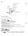
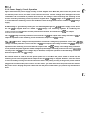
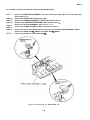
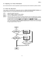
2.1 Printer Mechanism Operation
This section describes the printer mechanism of the FX-870/l 170 printer and explains how the printer works.
The FX-870/l 170 printer mechanism features a 9-pin impact dot printhead for seriaI Printin9. It has four main
parts: 1) the printhead mechanism, 2) the carriage movement mechanism, 3) the paper feed mechanism, and
4) the ribbon advance mechanism. Each of these is described below.
2.1.1 Printhead Mechanism
The printhead mechanism consists of the printhead itself, the ink ribbon, and the platen. The printhead contains
a column of 9 wires. Each of these wires has a drive coil which causes the wire to move in and out of the
printhead to print each dot. The four steps below describe how these driving wires work.
(1) The control circuit outputs drive signals to the printhead drive circuit. This changes the printhead drive
voltage, and current flows through the corresponding printhead coil. The coil acts as a solenoid and
generates a magnetic force.
(2) Thisinducedforce causesthe plate toapproach the coil rod andtheassociated dotwire is rapidly ejected
to impact on the platen.
(3) The dot wire presses the ink ribbon up against the paper as it hits the platen and in this way prints a dot
on the paper.
(4 As soon as the current through the coil is switched off, the force induced in the coil rod stops. The plate
then returns to its original position (the position assumed before the coil was energized) through the
action of the plate spring. After the dot wire hits the platen, the rebounding force of hitting the platen works
with the wire resetting spring to pull the wire back to its original position.
2-1
.
REV.-A
Figure 2-1 shows the action of the printer mechanism when a single dot is printed.
c- -.- ., .
“
Platen
Ribbon Mask
Dot Wire
Wire Resetting Spring
Stopper
\
\
)b
.ctuatlngT:-Rbf)cl
Paper
B$l=lieaclDrivingCOil
Actuating Plate Spring
Figure 2-1. How the Printhead Works
The printhead tends to heat up after a period of continuous printing. To minimize the dot wire drive coil
overheating, the head is equipped with a thermistor that can detect the head temperature. When the
thermistor detects changes in the printhead temperature, the voltage signal changes. The CPU detects the
voltage change and stops printing until the head temperature cools.
The printhead is also used asa buzzer. Head driving coils move allthedotwires backandforth atafrequency -.,,
of 1.5 KHZ for 40 I.M without impacting the platen, so that the wires vibrate. The vibrating dot wires sound like{
.=:
a buzzer.
-.. ,.
2-2
REV.-A
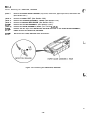
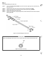
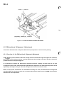
‘ 2.1.2 Carriage Mechanism
The timing belt is connected to the lower side of the carriage. With the printhead installed, the carriage moves
in either direction along the carriage guide shaft. The carriage (CR)motor (a stepping motor) drives the timin9
belt which moves the carriage. The home position (HP) sensor detects the home position of the carriage.
NOTE: Carriage initialization for the 80-coIumn and 136-column models are different.
Timing Belt
Puny
/
CR
0
‘etec’Or’Hp >\\!!! “~d
3
\\-\@/A
Base Frame
\
‘
\
w
Figure 2-2. Carriage Operation
2-3
w
.
REV.-A
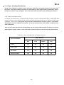
2.1.3 Platen Gap Adjustment
&>.,
Theplatengap (the gap between the platen andtheprinthead) can beadjustedto allowthe printerto use paper a
of differentweights orthicknesses. When the platen gap adjust lever is moved forward or backward, the carriage
guide shaft rotates. This rotation moves the carriage either toward or away from the platen and changes the
platen gap. Setting the adjust lever to position 2 (the 5th slot from the top) turns off the platen gap switch,
which slows down the printing speed of the printerto protect the printhead. The PG detector detects the position
of the adjust lever. The correct platen gap is 0.38mm * 0.02mm with the adjust lever set to position O.
Printhead
t
Platen Gap
~m,
Adjustment Slot
.
$
----
-.
.::,
Lever, G, Adjust
4“
/0
Detector, PG
Figure 2-3. Platen Gap Adjust Lever
“.. . . ..
2-4
REV.-A
I
2.1.4 Paper Handling Mechanisms
During normal operation, the paper is fed to the printer, advanced to the specified position, and ejected from
the printer. These paper handling operations are performed by various paper handling mechanisms, such as
the tractors, platens, rollers, and gears. This section describes the printer’s paper handling mechanisms.
2.1.4.1 Paper Feed Mechanisms
Cut sheets are fed by friction. Continuous paper is fed by a tractor. There are three ways to feed paper with
tractors: the push tractor method, the pull tractor method, and the push-pull tractor method. During normal
operation, the printer is set up with only one tractor, which functions as either a push or a pull tractor,
depending on where it is attached on the printer. To use the push-pull tractor feed method, an optional tractor
must be attached.
There are four paper entrances for feeding paper into the printer. Different paper entrances are used for
different types of paper. Table 2-1 lists which paper entrances can be used with each paper feed method.
Table 2-1. Paper Feed Methods and Paper Entrances
Paper Entrance
Paper Feed Method
Rear
Front
Bottom
Top
Friction
No
OK
No
OK
Push Tractor
OK
OK
No
No
Pull Tractor
OK
OK
OK
No
Push-pull Tractor
OK
OK
No
No
2-5
.
REV.-A
2.1.4.2 Paper Advance Mechanisms
-,,>, >
This section describes how the friction advance and tractor advance mechanisms work to advance the PaPer6
...
through the printer.
(1) Friction Advance Method
The paper is held between the platen and paper guide rollers and between the paper tension roller and paper
tension unit cover. The PF motor pinion gear, turning in the direction of the black arrow, drives the paper
advance reduction gear. The paper advance reduction gear turns the platen gear and the paper tension roller
gear. The paper advances in the direction of the white arrow. Figure 2-4 illustrates the friction advance method
when the paper is fed through the top paper entrance.
In the friction advance method, the paper guide roller spring holds the paper against the platen. You can
release this pressure and free the paper by setting the release lever to the tractor feed position.
i-.
Paper (Cut Sheet)
Paper Advance Reduction Gear
~otor, PF
Figure 2-4. Friction Advance Operation Using the Top Paper Entrance
2-6
REV.-A
(2) push Tractor Method
When the push tractor method is used with the rear entrance, the torque generated by the PF motor is
transmitted to the push tractor gear through the PF motor pinion gear, paper advance reduction gear, and
tractor reduction gear. When the PF motor pinion gear turns in the direction of the black arrow, thetractorgear
rotates in the direction of the black arrow and thus feeds the paper into the printer. The paper is advanced
by the platen and the paper tension roller, which are also driven by the PF motor through the train of gears.
When the push tractor method is used with the front entrance, the torque generated by the PF motor is
transmitted to the push tractor gear through the PF motor pinion gear, paper advance reduction gear, platen
gear, and the train of gears in the front pan of the printer. When the PF motor pinion gear turns in the direction
of the black arrow, the tractor gear rotates in the direction of the black arrow and thus feeds the paper into
the printer. The paper is advanced by the paper drive roller and the platen, which are also driven by the PF
motor through the train of gears.
In the push tractor method, the release lever issetto one ofthetractor positions to release the pressure between
the paper advance roller and the platen, Figure 2-5 illustrates push tractor operation when the paper is fed
through the rear paper entrance. Figure 2-6 illustrates push tractor operation when the paper is fed through
the front paper entrance.
Paper (Continuous)
\
‘7perTensi0nR0”er
\Lu-
Push Tractor
.
.
\\b./ \ \
~> Tractor Gear
~/A Tractor Reduction G ear
~(~~~ ,pFMotor P i n i o n Gear
Paper Ten
‘w’
Motor, PF
/
$aper Advance
Reduction Gear
Figure 2-5. Push Tractor Operation Using the Rear Paper Entrance
2-7
REV.-A
Paper (Continuous)
& \
\
/RollerGe~~
t-
\
Motor, PF
Paper Advance
Reduction Gear
Drive Roller Gear
/
Push Tractor
\
Push Tractor Gear
Figure 2-6. Push Tractor Operation Using the Front Paper Entrance
-..
f
.,
. ,.-
2-8
REV.-A
(3) pull Tractor Method
The pull tractor advances paper in basically the same way as the push tractor. The push tractor is installed
at the paper entrance and pushes the paper into the printer mechanism. The pull tractor, however, is installed
at the paper exit and pulls the paper out of the printer mechanism. As the result, the paper tension unit is not
required.
Figure 2-7 illustrates pull tractor operation when the paper is fed through the bottom paper entrance.
Paper (Continuous)
t,
Pull Tractor
J
/
///”
/-’’+”
~ull Tractor Gear
m
(?(\
ML=*
\
Tractor
~ /Reduction
Gear
Paper Drive
Motor, PF
\~[~/
Paper Drive Rolle;Gear
w
\
Paper Advance
Reduction Gear
\
Platen Gear
Figure 2-7. Pull Tractor Operation Using theBottom Paper Entrance
2-9
REV.-A
A,
c
: .’
(4) push-pull Tractor Method
The push-pull tractor method is a combination of the push and pull tractor methods. Two tractors are used
to advance the paper: one at the front paper entrance and the other at the rear paper entrance. They operate
simultaneously to push and pull the paper through the printer mechanism. Figure 2-8 illustrates push-pull
tractor operation when the paper is fed through the rear paper entrance. Figure 2-9 illustrates push-pull tractor
operation when the paper is fed through the front entrance.
Paper (Continuous)
./\
~
dv’
,/
/
,. /
?;;:?=::
..
8
=.
.
Pull Tractor
,:::,,,,,,
@
\
‘.
/ Push Tractor
Yii!ifx,pushTractorGear
~d
1
/
Tractor Reduction Gear
PF Motor Pinion Gear
Pul
/
Paper Advance
Reduction Gear
klotor, PF
Figure 2-8. Push-Pull Tractor Operation Using the Rear Paper Entrance
2-1o
i-.
REV.-A
Paper (Continuous)
,
Pull Tractor
Paper Drive Roller
\\
,/
J
Pull Tractor Gear
A Tractor Reduction Gear
/
\
1 PF Motor Pinion Gear
. ’
/
<
~..
\
—
@
=
Motor, PF
\
Paper Advance Reduction Gear
\
\
Platen Gear
‘.
Paper Drive Roller Gear
\\
Push Tractor Gear
Push Tractor
Figure 2-9. Push-pull Tractor Operation Using the Front Paper Entrance
2-11
REV.-A
(5) Release Lever
The release lever is used to select friction or tractor feeding or release the paper. When the release lever is
o.;.-
set to the friction feed position, the paper guide rollers are pressed against the platen. When it is set to one
of the tractor feed positions, this pressure is released and the paper guide rollers are separated from the
platen. When it is set to the paper free position, the paper drive roller and the lower paper guide roller at the
front entrance are separated from each other. Figure 2-10 illustrates the release lever. Figure 2-11 shows the
function of each release lever setting.
Paper
*a.
. . -
Right Frame
Release Shaft
Detector, RELEASE
Figure 2-10. Release Lever
,-..
Release Lever
N
-!!
=4
I
Friction Feed (Front, Top)
/
cl! I
Push Tractor (Front)
Pull Tractor (Front, Rear)
(Bottom) Push-Pull Tractor (Front)
:C
I
! cl
‘K Pull Tractor (Front, Rear)
Push Tractor (Rear)
(Bottom) Push-Pull Tractor (Rear)
\
I II
‘
Paper Free
II
GA ‘j
Figure 2-11. Release Lever Setting Functions
2-12
,:
t .,. - ~
REV.-A
2.1.4.3 Paper Paths
This section describes the various paths the paper follows through the printer mechanism. The various paper
paths are divided into four groups depending on the entrance(toPt rear, bottomf or front) the PaPer is fed from”
Note: The front PE (paper-end) detector is located in front of the printer mechanism and the rear PE detector
is located behind the printer mechanism.
(1) Top entrance
Figure 2-12 shows the paper path for friction feeding using the top entrance. The top entrance is used only
for friction feed method. When the top entrance is used, the rear PE detector senses when the paper is out.
Paper (Cut Sheet)
Paper Tension Roller
Detector, PE (Rear)
Paper Guide Rollers
Figure 2-12. Paper Path for Friction Feeding Using the Top Entrance
2-13
.
REV.-A
(2) Rear entrance
~~:.,
Figures 2-13 and 2-14 show the paper paths fortractorfeeding using the rear entrance. The rear entrance can
be used with any of the following paper feed methods: the push tractor feed method, the pull tractor feed
method, or the push-pull tractor feed method. When the rear entrance is used, the rear PE detector senses
when the paper is out.
Paper (Continuous)
Paper Tension Roller
Push Tractor
Detector, PE (Rear)
Paper Guide Rollers
Figure 2-13. Paper Path for Push Tractor Feeding Using the Rear Entrance
.
Paper (Continuous)
\
Printhead
/
\\
f Detector, PE (Rear)
Paper Guide Rollers
Figure 2-14. Paper Path for Pull Tractor Feeding Using the Rear Entrance
2-14
REV.-A
Paper (Continu
Printhead
ctor
ear)
Paper Guide Rollers
Figure 2-15. Paper Path for Push-pull Tractor FeedingUsing the Rear Entrance
(3) Bottom entrance
Figure 2-16 shows the paper path fortractorfeeding using the bottom entrance. The bottom entrance is used
only for pull tractor feeding. When the bottom entrance is used, the front PE detector senses when the paper
is out.
Paper (Continuous)
Paper
Detector, PE (Front)
\
Lower Paper Guide Roller
Figure 2-16. Paper Path for Pull Tractor Feeding Using the Bottom Entrance
2-15
.
REV.-A
~:>1
c
-..
(4) Front entrance
Figures 2-17 through 2-20 show the paper paths for the front entrance. The front entrance can be used with
any of the following paper feed methods: the friction feed method, push tractor feed method, pull tractor feed
method, or push-pull tractor feed method. When the front entrance is used, the front PE detector senses when
the paper is out.
Paper (Continuous) \
Paper Tension Roller
Pri‘nthead
Paper Drive Roller
Detector, PE (Front)
\
Lower Paper Guide Roller
Figure 2-17. Paper Path for Friction Feeding Using the Front Entrance
~.-.,
Paper (Continuous)=
Paper Tension Roller
.:,. $j~
. , %:.
@j
,Platen
—
-.. . .
Paper
..
\
w
L-J\
Lower Paper Guide Roller
XmJ
Detector, PE (Front)
Push Tractor
-..
Figure 2-18. Paper Path for Push Tractor Feeding Using the Front Entrance
2-16
REV.-A
Paper (Continuous)
Paper Drive Roller
..
Detector, PE (Front) \
Lower Paper Guide Roller
Figure 2-19. Paper Path for Pull Tractor Feeding Using the Front Entrance
/
.
Paper (Continuous)
Paper Drive Roller
Lower Paper Guide Roller
Detector, PE (Front)
Push Tractor
Figure 2-20. Paper Path for Push-pull Tractor Feeding Using the Front Entrance
2-17
.
REV.-A
2.1.4 Ribbon Advance Mechanism
i...
c‘“”
The ribbon is held between the ribbon advance roller (ribbon driving gear) and the ribbon pressure roller.
When the carriage moves ontheshaft, the timing belt turns the belt driven pulley, andthetorque is transmitted
to the ribbon driving gear through the train of gears. The ribbon driving gear rotates counterclockwise no
matter what direction the carriage moves, because the planetav gear is used in the gear linkage.
Table 2-2. Ribbon Advance Gear Linkage
I
Gear Linkage
Direction of Carriage Movement
Left to right
Belt driven pulley ● Gear (1) ● Gear (2) ~
(indicated by the black arrow)
Ribbon driving gear
Right to left
Belt driven pulley @ Gear (1) O Gear (3) 0
(indicated by the white arrow)
Gear (4) 0 Ribbon-driving gear
$Y,
The ribbon brake spring, attached to the exit slot of the cartridge case, prevents slack in the ribbon and keeps
the ribbon tension at an appropriate level. The ribbon mask prevents the ribbon from brushing against the
paper.
Ribbon Advance Roller \
Ribbon Pressure Roller
Ink Ribbon
‘.
/
Mask
Gear
Ribbon
Brake
#
Gear (2)
\
*
o
+
0
“’
D r i v i n g G e a r , &*
ge
Figure 2-21. Ribbon Advance Mechanism
2-18
REV.-A
2.2 Power Supply Operation
The FX-870/l 170 printer is powered by either of the two power supply boards: 120 VAC power supply board
(BOARD ASSEMBLY, C076 PSB) or 220/240 VAC power SUPPIY board (BOARD ASSEMBLY, C076 pSE). These
boards output the DC current necessary to drive the printer control circuits and the printer drive mechanism.
Fuse F1 (2.5A/125 V for C076 PSB or 1.25 lV250 V for C076 pSE) is used to Protect the Power suPPIY circuit
of each board in case of a short circuit.
Table 2-3. Power Supply Input Voltages and Fuse Ratings
1I
C076 PSB
I
C076 PSE
Fuse F1 Rating
Input Voltage
Board
I
I
I
I
103.5-132 VAC
198-264 VAC
I
I
2.5 AJ125 V
7.25 lV250 V
I
I
2.2.1 Power Supply Overview
The power supply board has two power output lines that supply power to the control circuits and the drive
mechanisms. Table 2-3 lists the components (pans or assemblies) of the printer that are powered by these
two DC voltages.
Table 2-4. Power Supply Output Voltages and Applications
Applications
Output voltage (DC)
+35 v
CR (carriage) motor drive
PF (paper feed) motor drive
Printhead drive
+5 v
Main control board logic circuitry
Sensors
Control panel LEDs
PF (paper feed) motor hold
2-19
REV.-A
2.2.2 Power Supply Circuit Operation
Figure 2-22 shows the power supply circuitry in block diagram form. When AC power enters the printer from
, :.,,.
<
an external power source, the filter circuit removes the noise. The AC voltage then undergoes full wave
rectification and is smoothed to produce direct current. The voltage is then fed through the switching circuit
and the secondary smoothing circuit to produce a stepped down +35 VDC voltage. A +35 VDC detector circuit
is connected to the switching circuit. This feedback control arrangement ensures a stable +35 VDC voltage
supply.
A+5VDCvoltage is generated by feeding the +35 VDCvoltagethrough the +5VDC power supply circuit, where
the +35 VDC is stepped down to a stable +5 VDC voltage. The switching regulator IC containing the
overcurrentiovervoitage control circuits performs this function. It controls the +5 VDC line output.
The +5 VDC voltage overload protection circuit cuts the +5 VDC line output if the voltage exceeds +7 VDC. It
stops the operation of the switching circuit and then the output of +35 VDC voltage.
The+35VDC line has a voltage overload protection circuit and a voltage drop protection circuit. The +35VDC ~
voltage overload protection circuit cuts the +35 VDC line output if the voltage exceeds +36 VDC. It stops the ““
operation of the switching circuit and then the output of the +35 VDC voltage. The voltage drop protection
circuit protects the printer against a sudden voltage drop that maybe caused by a short circuit in the seconda~
circuitry of the +35 VDC line. If a voltage drop is detected, it stops the operation of the switching circuit and
then the output of the +35 VDC voltage.
An external switch is used to turn the printer power on or off. When the power switch is turned off, the
switching circuit is de-energized and the output of the +35 VDC voltage is stopped. However, since the switch
is in the secondary circuitry, the current continues to flow in the primary circuitry as long as the printer remains
plugged into an external AC power source. For this reason, you must disconnect the printer from the external
AC power source. Unplug the power cable from the AC power outlet before you perform any maintenance
work.
-.
f’
., .
2-20
REV.-A
I
I
I
I
1
Primary
Secondary
I
1
1
I
1
Full Wave
Rectification
Circuit
— Smoothing
Circuit
Switching
Circuit
;
I
I
1
1
.
<
Smoothing
Circuit
4
+ 3 5 VDC
m
I
1
1
I
1
1
1
9
l------
Filter Circuit
1
I
1
1
I
I
I
I
1
I
1
1
I
1
1
t
1
I
AC input
+5 v
Switching
Regulator
................
+5V
Over Current
Control Circuit
----..-.....---+5V
Over Voltage
Control Circuit
.
+ +5 VDC
1
ZD51
Photo- +
coupler
II
{
Photo- +
coupler
-
+35 V Line
Detector Circuit
+5 V Line Voltage
Overload
Protection Circuit
ZD53
—
8A
1
1
1
1
I
1
1
1
1
1
I
I
t
t
I
I
I
I
I
I
I
I
1
I
I
I
I
1
t
1
1
1
1
+35 V Line
Voltage Drop
Protection Circuit
—
Figure 2-22. Power Supply Circuit Block Diagram
2-21
~ Switch
REV.-A
2.3 Control Circuit Operation
The control circuit consists of two circuit boards: the C094 MAIN (the main control circuit board) and the C094
PNL (the control panel circuit board). This section describes the operation of these boards.
2.3.1 Control Circuit Operation Overview
The CPU on the C094 MAIN is the 8-bit TM P90C041F microprocessor (9.83 MHz). It oversees control of all the
components of the printer. The E05A66YA gate array contains various memory management functions that
control the memory assignment and 1/0 areas. The output signals from each detector are sent to the analog
input poti of the CPU. The signals from the control panel are sent to the gate array, which in turn sends LED
signals to the control panel. The two motors (CR and PF) are controlled by signals sent from the stepping
motor control port of the CPU. Figure 2-23 shows the control circuits in block diagram form.
7
ETROM
4K BIT
Ic 5C1
I
1-
7
)
b
n-
1
1
CONTROL
PANEL
BUITONS
AND LEDS
PG
SENSOR
h-
. .
—
1
PE FRONT
SENSOR
.
RELEASE
PE REAR
LEVER
SENSOR
SENSOR
m
WE-1
CR
HOME
SENSOR
D
HEAD
THERMISTOR
m Data bus
~
+5vDc
~
+35vDc
k-~ Addrt?ss
Figure 2-23. Control Circuit Block Diagram
2-22
bus
REV.-A
Figure 2-24 shows the data flow from the host computer to the printhead. Data sent from the host computer
is converted to image data and transmitted to the printhead through the gate array.
CPU
El-
---L
-1
~ Input
buffer
Print data
conversion
~ Image
buffer
Image data
transfer
Figure 2-24. Data Flow
2-23
.
REV.-A
Table 2-4 lists the functions of the main components of the C094 MAIN.
Table 2-5. Functions of Main Components of C094 MAIN
Functions
IC or Circuit
TMP90C041F (2C1)
Receives data from the host computer and loads it to the input buffer in RAM.
Expands the input data held in the buffer to create image data. Loads the image
data to the image buffer in RAM. Transfers the image data to the printhead
drive circuit. Also controls various printer mechanism parts, such as the
motors.
E05A66YA (IC4)
This gate array mainly performs the following five functions:
“ Memory management
●
Centronics l/F control
●
Control panel control
E2PROM control
●
Printhead drive circuit control
●
PROM (IC3)
The PROM contains the program that runs the CPU.
RAM (IC2)
The RAM contains the CPU working area and the buffers.
E2PROM (5CI)
The EZPROM is used to store information such as the top-of-form position.
UPA1475H (lCl)
Drive circuit for PF motor
SLA7024M (IC5)
Drive circuit for CR motor
2-24
REV.-A
2.3.2 Reset Circuit
The control circuits are initialized when the RESET signal is issued. The reset operation occurs under these
two conditions:
(1) Power on reset
Immediately after the power is turned on, +35 VDC is rapidly generated. Because it takes a moment for the
voltage at ZD2 to reach +31.5 V, the voltage at the DISC terminal on the gate array does not reach +5 VDC
until capacitor C24 is fully charged. A similar integration circuit is provided in the gate array and further
delays the output of the ROUT signal. This low level is used as a reset signal.
(2) INIT signal reset
The reset signal is also issued when the INIT signal is sent from the host computer.
Figure 2-25 shows the power on reset circuit.
GA (IC4)
+5VDC
+35VDC
L
P’-’’--5’
+
RIN
4
DISC ROUT
55
‘D2~
D 7
~R31
I
R80
15
d
R79
C P U (IC2CI) 15
RESET
C24
i
Figure 2-25. Power On Reset Circuit
2-25
.
REV.-A
2.3.3 Sensor Circuits
(
.>~
The FX-870/l 170 printer has the following sensors: CRHOME, pE (FRONT), pE (REAR), pG (platen 9ap),
RELEASE LEVER, and HEAD TEMPERATURE. All the sensors are momentary switches, except the PE (REAR)
sensor, which is a photo diode, and the HEAD TEMPERATURE sensor, which is a thermistor.
In addition to the sensor circuits, the +35 V monitor circuit and the Vref circuit are also provided. The +35 V
monitor circuit is used to set the pulse length of the head drive signal. If the voltage of the +35 V line drops
below +31 V (approx.), the printer stops printing fora while. As soon asthevoltage recovers, the printer starts
to print at a half speed. (The PF motor also slows down.) The Vref circuit is used to supply the reference voltage
for the A/D convertor in the CPU.
The CPU constantly monitors the printhead temperature. If the printhead temperature exceeds the maximum
level, the printer stops printing until the temperature drops to a certain level. When the printhead temperature
cools down, the printer resumes printing automatically.
.
>
Figure 2-26 shows the sensor circuit block diagram.
..-.
CPU (lC)
CRHOME
PEFRONT
PEREAR
PG
+35 v
RELEASE
~
LEVER
+35 Voltage Monitor
+35 v
Head Temperature
,., ,. \
{.,“ ~
Vref
ZD1
7)7
Figure 2-26. Sensor Circuit Block Diagram
2-26
REV.-A
2.3.4 Carriage Motor Drive Circuit
The carriage motor drive circuit controls the CR motor. An open loop, constant current drive arrangement runs
the CR motor. 2-2 and 1-2 phases are used to excite the motor. A 2-2 phase step is equivalent to a 1-2 phase
step doubled. Table 2-5 describes the motor drive modes.
The CR motor drive circuit of the SLA7024M (IC6) detects and regulates the amount of current flowing in the
carriage motor coil. The current flowing through the coil varies depending on the speed of the CR motor. The
CPU sets the amount of current via the l/O port of the gate array. Signals are sent to the ports (L, M, HOLD)
on the SLA7024M. The SLA7024M sets the coil current depending on the CR motor speed.
The printer may stop printing to protect the CR motor from overheating if a continuous printing of short
columns (less than 10 columns) is repeated.
The printer uses CPU ports P60 to P63 exclusively to control the CR motor.
CPU (IC2C1)
1I
P60
INA
CRA
P61
INB
CR-A i
P62
IN-A
CRB
P63
IN-B
CR-B
E05A66YA (IC4)
G
Data
Bus
PC4
LOW
PC5
MIDDLE
PC6
MOTOR
ASSEMBLY, CR
r --------- . --.-----,
I
1
1
I
1
t
,
I
I
8
1
[
lqfp-1
I
1,
-----------------IL
1
L
8
8
1
I
t
I
1
1
1
I
1
1
A
CRCOM
Gp
HOLD
l-l
1
GiD
<CR MOTOR>
4-ph, 200-P HB type pulse motor
35VDC
+8Y0 -7~o
5.4Sh10Y0
(per phase) (at 25 ‘C)
Figure 2-27. Carriage Motor Drive Circuit
Table 2-6. Carriage Motor Drive Modes
Speed mode
PPS
Excitation phase
Characters printed
4/3
4468
2-2
Superdraft
9/8
3840
2-2
Superdraft copy
1
3357
2-2
Draft 10 cpi
5/6
2800
2-2
2/3
2240
2-2
4/3 High duty
1/2
1680
1-2
NLQ
5/1 2
1400
1-2
1/4
840
1-2
5/24
700
1-2
5/12 High duty
1/8
420
1-2
1/4 High duty
2-27
.
REV.-A
2.3.5 Paper Feed Motor Drive Circuit
.,%. ,
{:
The PF motor (a stepping motor) is used to advance the paper. The minimum advance rate is 1/216 inch. The
motor is a 2-2 phase, constant voltage drive motor. CPU ports (P70 to P73) are used to control the PF motor.
Phase data for the PF motor are outputted through these ports. PFA to PF-B are turned on or off within the
uPA1476H (lCl) depending on the phase data sent from the CPU.
When there is an output at A19 of the CPU, a +35 V voltage is supplied to the PFCOM terminal of the PF motor.
Otherwise, a +5 V voltage is supplied through D1 to hold the motor.
UPA1476H (lCl)
CPU
P70
PFAIN B1
cl
PF&N B2
C2
PFBIN B3
C3
P73 w PF~lN B4
C4
P72
P71
H
-d-
r
I
Q1
‘3:V
MOTOR
ASSEMBLY, PF
PF-A
:- - - - - - - - ‘ 1
:
PFB
+‘
PFA
:
I
PF-B
‘- - - ‘ - ‘ - ;
t
t
1
1
1
1
1
1
1
1
1
1
1
L---------------
F
---J
<PF MOTOR>
4-ph, 48-p PM type pulse motor
35W)C *1OYO
R5
61(2=3(2 (per phase) (at 25 “C)
A
D1
u
R49
+5V
Figure 2-28. Paper Feed Motor Drive Circuit
~“”’
...
2-28
REV.-A
2.3.6 Printhead Drive Circuit
The printhead drive circuit receives two types of signals; image data and the pulse length control signal.
Image data is created in the CPU, transferred to the gate array, and latched to the printhead. The pulse length
control signal is set by the CPU. The pulse length is adjusted referring to the voltage of the +35 V line. These
two types of signals are sent to the printhead to print each dot. Figure 2-29 shows the printhead drive circuit.
+35VDC
GA (IC4)
,35VDC C P U (IC2C1)
t
HEAD
Q14
DO-7
DO--7
HDP
P51
HPW
P83
HDN1
HDh9
Q2,Q4NQ6,
Q8,Q9-12
Figure 2-29. Printhead Drive Circuit
2.3.7 Parallel Interface Circuit
The parallel interface circuit controls the data flow from the host computer. When a STROBE signal is sent
from the host computer, the data is latched into the gate array (E05A66YA). Data is transmitted until a BUSY
signal is automatically sent back to the host computer to stop the data. Then the gate array outputs an IBF
signal to P82 (the interrupt signal port) of the CPU. The CPU then reads the data latched into the gate array
and, on completion of the reading, resets the BUSY signal to enable the host computer to send more data.
Figure 2-30 shows the parallel interface circuit.
E05A66YA (IC4)
CPU (IC2C1)
Parallel l/F
DO-7
STROBE
DINO-7
-
DATAO-7
STB
IBF
------- ~-------- --1
1
1
1
BUSY -
- - - - - - - i
BUSY
Figure 2-30. Parallel Interface Circuit
2-29
DO-7
P82
.
REV.-A
2.3.8 E2PROM Control Circuit
“4
c’
Figure 2-31 shows the E2PROM control circuit. The E2PROM is non-volatile memory containing information . .
such asthetop-of-form position. Because the E2PROM is a serial 1/0 device, the gate array converts the parallel
data (sent from the host computer) into serial data.
E2 PROM
([C5C1)
E05A66YA (IC4)
CPU (IC2C1)
Data Bus
SCL
SCK
SDA
SDA
Figure 2-31. E2PROM Control Circuit
2-30
REV.-A
CHAPTER 3
DISASSEMBLY AND ASSEMBLY
..
3.1 Overview . . . . . . . . . . . . . . . . . . . . . . . . . . . . . . . . . . . . . . . . . . . . . . . . . . . . . . . . . . . . . . . . . . . . . . . . . . . . . . . . . . . . . . . . . . . . . . . . . . . . . . .3-1
3-1
3.1.1 Precautions . . . . . . . . . . . . . . . . . . . . . . . . . . . . . . . . . . . . . . . . . . . . . . . . . . . . . . . . . . . . . . . . . . . . . . . . . . . . . . . . . . . . . . . . .
..
3.1.2 TooIS . . . . . . . . . . . . . . . . . . . . . . . . . . . . . . . . . . . . . . . . . . . . . . . . . . . . . . . . . . . . . . . . . . . . . . . . . . . . . . . . . . . . . . . . . . . . . . . . .3-1
..
3.1.3 Service Checks After Repair . . . . . . . . . . . . . . . . . . . . . . . . . . . . . . . . . . . . . . . . . . . . . . . . . . . . . . . . . . .3-2
...
3.1.4 Screw Specifications . . . . . . . . . . . . . . . . . . . . . . . . . . . . . . . . . . . . . . . . . . . . . . . . . . . . . . . . . . . . . . . . . . . . . . 3-3
...
3.2 Disassembly and Assembly. . . . . . . . . . . . . . . . . . . . . . . . . . . . . . . . . . . . . . . . . . . . . . . . . . . . . . . . . . . . . . . . . . . . . . . . 3-4
..
3.2.1 Pre-disessembly Procedures . . . . . . . . . . . . . . . . . . . . . . . . . . . . . . . . . . . . . . . . . . . . . . . . . . . . . . . . . . .3-5
3-6
.
.
.
.
.
.
.
.
.
.
.
.
.
.
.
.
.
.
.
.
.
.
.
.
.
.
.
.
.
.
.
.
.
.
.
.
.
.
.
.
.
.
.
.
.
.
.
.
.
.
.
.
.
.
.
.
.
.
.
.
..
3.2.2 Removing the PANEL UNIT
..
3.2.3 Removing the PRINTHEAD . . . . . . . . . . . . . . . . . . . . . . . . . . . . . . . . . . . . . . . . . . . . . . . . . . . . . . . . . . . . .3-7
.
3.2.4 Removing the HOUSING ASSEMBLY, UPPER . . . . . . . . . . . . . . . . . . . . . . . . . . . . . . . 3-8
3-9
3.2.5 Removing the PRINTER MECHANISM . . . . . . . . . . . . . . . . . . . . . . . . . . . . . . . . . . . . . . . . . . . . .
.
3.2.5.1 Removing the PLATEN ASSEMBLY . . . . . . . . . . . . . . . . . . . . . . . . . . . . . . . . . 3-1o
3.2.5.2 Removing the FRAME ASSEMBLY, REAR ........................3-11
. -12
3.2.5.3 Removing the MOTOR ASSEMBLY, CR . . . . . . . . . . . . . . . . . . . . . . . . . . . 3
3.2.5.4 Removing the MOTOR ASSEMBLY, PF . . . . . . . . . . . . . . . . . . . . . . . . . . . .3-13
.
3,2.5.5 Disassembling the GEAR TRAIN, PF . . . . . . . . . . . . . . . . . . . . . . . . . . . . . . . . 3-14
3.2.5.6 Removing the CARRIAGE GUIDE ASSEMBLY .................3-15
3.2.5.7 Removing the Ribbon Drive (RD) ASSEMBLY ..................3-17
3.2.5.8 Removing the Home Position (HP) DETECTOR ................3-18
3.2.5.9 Removing the Platen Gap (PG) DETECTOR ......................3-18
3.2.5.10 Removing the Front and
.
Rear Paper End (PE) DETECTORS . . . . . . . . . . . . . . . . . . . . . . . . . . . . . . . . . .3-19
3.2.5.11 Removing the DETECTOR, RELEASE . . . . . . . . . . . . . . . . . . . . . . . . . . . . .3-20
..
3.2.5.12 Arranging the Cables. . . . . . . . . . . . . . . . . . . . . . . . . . . . . . . . . . . . . . . . . . . . . . . . . . . . . . 3-21
.
3.2.5.13 Disassembling the Tractor Unit . . . . . . . . . . . . . . . . . . . . . . . . . . . . . . . . . . . . . .3-22
3.2.6 Removing the BOARD ASSEMBLY, C094 MAIN . . . . . . . . . . . . . . . . . . . . . . . . . . .3-23
3.2.7 Removing the BOARD ASSEMBLY, C076 PSB/PSE .....................3-24
s-i
REV.-A
LIST OF FIGURES
. -4
Figure 3-1. Flowchart for Disassembling the Printer . . . . . . . . . . . . . . . . . . . . . . . . . . . . . . . . . . . . . . . 3
Figure 3-2. Removing the PAPER GUIDE ASSEMBLY .......................................3-5
Figure 3-3. Removing the PANEL UNIT ..............................................................3.6
. -6
Figure 3-4. Connecting the FFC Cable to the Panel Unit . . . . . . . . . . . . . . . . . . . . . . . . . . . . . . . . . 3
.
Figure 3-5. Removing the PRINTHEAD . . . . . . . . . . . . . . . . . . . . . . . . . . . . . . . . . . . . . . . . . . . . . . . . . . . . . . . . . . . . . .3-7
Figure 3-6. Removing the HOUSING ASSEMBLY, UPPER ................................3-8
.
Figure 3-7. Removing the PRINTER MECHANISM . . . . . . . . . . . . . . . . . . . . . . . . . . . . . . . . . . . . . . . . . . . 3-9
3-1o
figure 3-8. Removing the PIATEN ASSEMBLY . . . . . . . . . . . . . . . . . . . . . . . . . . . . . . . . . . . . . . . . . . . . . . .
Figure 3-9. Removing the FRAME ASSEMBLY, REAR ....................................3-11
Figure 3-10. Removing the MOTOR ASSEMBLY, CR . . . . . . . . . . . . . . . . . . . . . . . . . . . . . . . . . . . . . 3. -12
. -12
Figure 3-11. Positioning the MOTOR ASSEMBLY, CR . . . . . . . . . . . . . . . . . . . . . . . . . . . . . . . . . . . 3
Figure 3-12. Removing the MOTOR ASSEMBLY, PF .......................................3-13
.
Figure 3-13. Disassembling the GEAR TRAIN, PF . . . . . . . . . . . . . . . . . . . . . . . . . . . . . . . . . . . . . . . . . . . 3-14
Figure 3-14. Positioning the LEVER, RELEASE for Insertion ..........................3-14
Figure 3-15. Removing the CARRIAGE GUIDE ASSEMBLY ............................3-15
.
Figure 3-16. Attaching the TIMING BELT . . . . . . . . . . . . . . . . . . . . . . . . . . . . . . . . . . . . . . . . . . . . . . . . . . . . . . . .3-16
Figure 3-17. Removing the RD ASSEMBLY . . . . . . . . . . . . . . . . . . . . . . . . . . . . . . . . . . . . . . . . . . . . . . . . . . . . . . 3-17
Figure 3-18. Removing the DETECTOR, HP . . . . . . . . . . . . . . . . . . . . . . . . . . . . . . . . . . . . . . . . . . . . . . . . . . . . .3-18
.
Figure 3-19. Removing the DETECTOR, PG . . . . . . . . . . . . . . . . . . . . . . . . . . . . . . . . . . . . . . . . . . . . . . . . . . . .3-18
.
.
Figure 3-20. Removing the DETECTORS, PE . . . . . . . . . . . . . . . . . . . . . . . . . . . . . . . . . . . . . . . . . . . . . . . . . . .3-19
Figure 3-21. Removing the DETECTOR, RELEASE . . . . . . . . . . . . . . . . . . . . . . . . . . . . . . . . . . . . . . . . . 3. -20
Figure 3-22. Arranging the Cables . . . . . . . . . . . . . . . . . . . . . . . . . . . . . . . . . . . . . . . . . . . . . . . . . . . . . . . . . . . . . . . . . . 3-21
..
Figure 3-23. Disassembling the Tractor Unit . . . . . . . . . . . . . . . . . . . . . . . . . . . . . . . . . . . . . . . . . . . . . . . . . .3-22
.
Figure 3-24. Position of the Cog . . . . . . . . . . . . . . . . . . . . . . . . . . . . . . . . . . . . . . . . . . . . . . . . . . . . . . . . . . . . . . . . . . . . . . 3-22
..
Figure 3-25. Removing the BOARD ASSEMBLY, C084 MAIN .........................3-23
Figure 3-26. Removing the BOARD ASSEMBLY, C076 PSB/PSE ...................3-24
LIST OF TABLES
‘7
f
-. ;
Table 3-1. Recommended Toois . . . . . . . . . . . . . . . . . . . . . . . . . . . . . . . . . . . . . . . . . . . . . . . . . . . . . . . . . . . . . . . . . . . . . . 3-1
...
Table 3-2. Equipment Required for Maintenance ..............................................3-l
Table 3-3. Inspection Checklist for Repaired Printer . . . . . . . . . . . . . . . . . . . . . . . . . . . . . . . . . . . . . . . . 3-2
.
Table 3-4. Abbreviations Used for Screws . . . . . . . . . . . . . . . . . . . . . . . . . . . . . . . . . . . . . . . . . . . ..............3-3
Table 3-5. Screw Types and Abbreviations .......................................................3.3
S.ii
REV.-A
,
3.1 Overview
This section describes the information you need to know before you disassemble or assemble the printer.
3.1.1 Precautions
Follow the precautions below before you disassemble or assemble the printer.
WARNING
Before disassembling, assembling, or adjusting the printer, disconnect the power supply cable from
the AC power outlet. Failure to do so may cause physical injury. The power switch is wired in the
secondary circuitry. Therefore, the printer’s primary circuitry remains live even after the power switch
is turned off.
7
CAUTION
To maintain optimum printer operation, use only the recommendedtools for maintenance work.
Also only the lubricants recommended in Chapter 6. Adjust the printer only as described in this
manual. (See Chapter 4.)
3.1.2 Tools
Tables 3-1 and 3-2 list the recommended tools needed to disassemble, assemble, or adjust the printer. Use
only tools that meet these specifications.
Table 3-1. RecommendedTools
Tool
Part No.
Round-nose pliers
B7404OO1OO
Nippers
B7405OO1OO
Tweezers
B741OOO1OO
Soldering iron
B7402OO1OO
E-ring holder #2.5
B740800400
Phillips screwdriver no.2
B743800200
Normal screwdriver
B743OOO1OO
Thickness gauge
Note: All the tools in the table above are commercially available.
Table 3-2. Equipment Required for Maintenance
Description
Specification
Multimeter
Oscilloscope
20 MHz
3-1
REV.-A
3.1.3 Service Checks After Repair
Before you send the printer back to the customer, fill in the checklist in Table 3-3 to note the current state of
the components. This checklist facilitates servicing and shipping.
Table 3-3. Inspection Checklist for Repaired Printer
Is Check Required?
Items to Check
Category
Component
Printer
Printhead
•
Are any wires broken?
❑ Checked, R Not necessary
Are any wires worn out?
l
Checked,
•l Not necessary
Carriage
Does the carriage move smoothly?
❑ Checked, ❑ Not
mechanism
❑ IMovement
•
features
necessary
noisy, Mechanism
dirty,
l
(Mechanism oily
❑
Is the
• carriage motor at the correct
Checked, lNot necessary
temperature and not overheating?
Paper
Is paper
advancing smoothly?
•
advance
❑ Movement noisy, ❑ Mechanism
mechanism
Mechanism oily
Paper path
l
❑ Checked, Not
necessary
dirty,
• paper advance motor running at the
Is the
l
❑ Not necessary
Checked,
correct temperature and not overheating?
Is the
• type of paper in the printer feeding
l
Checked,
•l Not necessary
smoothly?
Adjustment
Is the
• tractor feeding the paper correctly?
❑
Is the
• paper path clear of all obstructions?
Is the
• platen free of damage?
l
Checked,
•l Not necessary
l
❑ Not necessary
Checked,
Ribbon mask
Is ribbon
mask free of distortion?
•
Self-print test
Was •the self-print successful?
On-1ine test
Printhead
•
Was the on-line test successful?
l
Checked,
•l Not necessary
❑ Checked, lNot necessary
❑ Checked, ❑ Not necessary
Printing
•
Is the bidirectional alignment adjusted
Is the platen gap adjusted correctly?
Checked, lNot necessary
l
Checked,
•l Not necessary
l
Checked, ❑ Not necessary
correctly?
System
❑ Checked, ❑ Not
ROM version
The ROM version is XXX.
Shipment
Has the ribbon been removed?
❑ Checked, ❑ Not necessary
l
Have all the required parts been included in Checked,
❑ Not necessary
necessary
upgrade
•
the shipment?
3-2
FHI.-A
3.1.4 Screw Specifications
This chapter uses abbreviations for small parts, such as screws and washers. Tables 3-4 and 3-5 list these
abbreviations.
Table 3-4. Abbreviations Used for Screws
Part Name
Abbreviation
CBB
Cross-recessed Bind head B tight screw
CBC
Cross-recessed Bind head C tight screw
CBN
Cross-recessed Bind head N tight screw
Cross-recessed Bind head S tiaht screw
CBS
Table 3-5. Screw Types and Abbreviations
Head
Body
Top
Washer
(assembled)
Side
1.~ross–recessed head 1.~ind
1 .~ormal
@
——
b
2.~lotted head
0=
1.~lain washer
(Q@
2,
(with IJotch)
~-tight
\
I !’1;.1 ,!~\ ! : ,
ma
2.@tside toothed
lock washer
2,~an
e
.—
‘=;
Q@
0=
3.Qlp
——
4.~apping
I ~~~~~
3.~pring washer
mo (Q)@
b
4. ~russ
— .
\
-9
b
3-3
REV.-A
3.2 Disassembly and Assembly
This section describes the procedures for disassembling and assembling the main components of the ““
printer. In general, you can install a component in the printer by simply reversing the procedure for removing
the component. Therefore, this chapter does not describe assembly procedures in most cases.
If necessary, special notes on assembling or adjusting a component are given at the end of the description
of each procedure. Be sure to follow the instructions in these notes.
WARNING
Before disassembling the printer, read the warning in Section3.1.
CAUTION
Before disassembling any part of the printer, remove the paper and the ink ribbon. Also disconnect
the interface cable.
Note: Exploded diagrams in the appendix show how the components fit together. Refer to them as
.L-=-,
necessary. The flowchafi below shows the order in which you need to disassemble the printer.
1
START 1
Disconnect the printer’s power cord and interface cable.
I
1
EsEEl
mm m
-:-s
$..
Figure 3-1. Flowchart for Disassembling the Printer
3-4
REV.-A
3.2.1 Pre-disassembly Procedures
[STEP 11
Remove the PAPER GUIDE ASSEMBLY, top cover, front cover, paper eject cover, and tractor unit.
LY
Front Cover
Figure 3-2. Removing the PAPER GUIDE ASSEMBLY
Note: Remove the paper eject cover and the tractor unit by pushing and releasing the hooks at both
sides. When remounting them, be sure to snap these hooks on the projecting parts.
3-5
REV.-A
3.2.2 Removing the PANEL UNIT
[STEP 11
.3
[
Remove the PAPER GUIDE ASSEMBLY, top cover, front cover, paper eject cover and tractor unit.
(See Section 3.2.1.)
[STEP 21
Push the two clips on the bottom of the panel unit and remove the PANEL UNIT.
[STEP 3]
Remove the flexible flat cable (FFC cable).
PAN
+
‘.m. -
Figure 3-3. Removing the PANEL UNIT
Assembly Note
The FFC cable must be connected properly, as shown below.
Plain Face
I
4
FFC Cable
Q4a
Face with exDosed
I
terminals at ~he end ~
~w’
of the cable.
Figure 3-4. Connecting
the FFC Cable to the PANEL UNIT
3-6
.-*
c..
:
REV.-A
3.2.3 Removing the PRINTHEAD
[STEP 1]
Remove the PAPER GUIDE ASSEMBLY, top cover, front cover, paper eject cover, and tractor unit.
[STEP 21
(See Section 3.2.1.)
Remove the two CBS (M3X8) screws and the FFC cable from the PRINTHEAD.
[STEP 31
Remove the PRINTHEAD.
Figure 3-5. Removing the PRINTHEAD
3-7
REV.-A
3.2.4 Removing the HOUSING ASSEMBLY, UPPER
“.:?.
f
[STEP 11
Remove the PAPER GUIDE ASSEMBLY, top cover, front cover, paper eject cover and tractor unit.
[STEP 21
(See Section 3.2.1.)
Remove the PANEL UNIT. (See Section 3.2.2.)
[STEp 31
Remove the three CBC (M4X15) screws securing the HOUSING ASSEMBLY, UppER. (There are
only two screws in the 80-column printer.)
[STEP 41
Push the two hooks through the cutouts located on the front cover to disengage the hooks from
the plates. Lift up the front side of the HOUSING ASSEMBLY, UPPER.
[STEP 51
Remove the HOUSING ASSEMBLY, UPPER.
CBC (M4X15)
.
HOUSING ASSEMBLY, UPPER
cut
-.
f.. . . .. . ~ Šˆ
Figure 3-6. Removing the HOUSING ASSEMBLY, UPPER
Note: The figure above shows the 136-column printer.
3-8
REV.-A
3.2.5 Removing the PRINTER MECHANISM
[STEP 11
Remove the PAPER GUIDE ASSEMBLY, top cover, front cover, paper eject cover and tractor unit.
(See Section 3.2.1.)
[STEP 21
[STEP 31
[STEP 41
[STEP 51
[STEP 61
Remove the PANEL UNIT. (See Section 3.2.2.)
Remove the HOUSING ASSEMBLY, UPPER. (See Section 3.2.4.)
Remove the four CBB (M4X12) screws securing the PRINTER MECHANISM.
Remove the CBS (M3X6) screw securing the INTERFACE COVER.
Disconnect the following connectors on the BOARD ASSEMBLY, MAIN: CN3 (2-pin# Blue)/ CN4 (2pin, White), CN5 (2-pin, Black), CN6 (6-pin), CN7 (2-pin, yellow), CN8 (ld-pinh CN9 (S-pin)r CN12
[STEP 71
(lO-pin), and CN13 (5-pin).
Remove the PRINTER MECHANISM.
CBB (M4X12)
h
+
1
la
I?’’CBS(M3X6)
‘
~ INTERFACE COVER
\
&
.
PRINTER MECHANISM
,
‘9
Figure 3-7. Removing the PRINTER MECHANISM
3-9
REV.-A
3.2.5.1 Removing the PLATEN ASSEMBLY
:).
(
[STEP 1]
Remove the PAPER GUIDE ASSEMBLY, top cover, front cover, paper eject cover and tractor unit.
[STEP 21
(See Section 3.2.1.)
Remove the PANEL UNIT. (See Section 3.2.2.) -
[STEP 31
[STEP 4]
Remove the HOUSING ASSEMBLY, UPPER. (See Section 3.2.4.)
Remove the two CBS (M3X8) screws securing the COVER, PLATEN.
[STEP 51
Disengage the teeth of the PLATEN SHAFT HOLDERS and rotate them.
[STEP 61
[STEP 7]
Remove the PLATEN KNOB.
Slide the PLATEN ASSEMBLY and remove it.
h
, C B S
(M3X8)
PLATEN KNOB
.DER
>,-,%,
,.
{’
, =.
Figure 3-8. Removing the PLATEN ASSEMBLY
3-1o
“
REV.-A
3.2.5.2 Removing the FRAME ASSEMBLY, REAR
[STEP 11
Remove the PAPER GUIDE ASSEMBLY, top cover, front cover, paper eject cover and tractor unit.
[STEP 2]
(See Section 3.2.1.)
Remove the PANEL UNIT. (See Section 3.2.2.)
[STEP 31
[STEP 41
Remove the HOUSING ASSEMBLY, UPPER. (See Section 3.2.4.)
[STEp 51
Remove the PLATEN ASSEMBLY. (See Section 3.2.5.1.)
[STEp 61
Remove the four CBS (M3X8) screvvs securing the LEFT FRAME of the pRINTER MECHANISM~
Remove the PRINTER MECHANISM. (See Section 3.2.5.)
and the nut and washer securing the LEVER, G, ADJUST. Remove the BUSHING, PARALLEL,
ADJUST. Remove the LEFT FRAME.
[STEp 71
Remove the FFC cables from the RIGHT FRAME of the PRINTER MECHANISM, and then the two
[STEp 81
CBS (M3X8) screws securing the RIGHT FRAME.
Remove the FRAME ASSEMBLY, REAR.
[STEp 91
Push the clip on the back of the FRAME ASSEMBLY, REAR. Slide out the FRAME, REAR.
Hexagon
=
Outside
Lock W
LE
FT F R A M E
.
CBS (M3X8)
BUS
<
P A P E R G U I D E A S S E M B L Y , R E A R ~ I /\\
Y>
Figure 3-9. Removing the FRAME ASSEMBLY, REAR
3-11
REV.-A
3.2.5.3 Removing the MOTOR ASSEMBLY, CR
[STEP 11
..,., ,
r
Remove the PAPER GUIDE ASSEMBLY, top cover, front cover, paper eject cover, and tractor unit. ‘
[STEP 2]
(See Section 3.2.1.)
Remove the PANEL UNIT. (See Section 3.2.2.)
[STEP 3]
Remove the HOUSING ASSEMBLY, UPPER. (See Section 3.2.4.)
[STEP 41
Remove the face screw (M3X7) securing the MOTOR ASSEMBLY, CR. After releasing the tension
[STEp 51
spring, disengage the TIMING BELT from the MOTOR ASSEMBLY, CR and hang it on the hook.
Disconnect the connector CN13 on the BOARD ASSEMBLY, C094 MAIN. Remove the MOTOR
ASSEMBLY, CR.
[STEp 61
Remove the two CBN (M3X6) screws on the back of the MOTOR ASSEMBLY, CR. Remove the
MOTOR ASSEMBLY, CR.
MOTOR ASSEMBLY, CR
Face Screw (M3X7) =?*
!
Spring .
\\
- i
‘-%
L F PLATE, BELT TENSION
!
.)
‘L
J
CBN
A
(M3X6)
~—.
\\\-
-- ..%
f :’
.., ,.,
Figure 3-10. Removing the MOTOR ASSEMBLY, CR
Assembly Note
Position the MOTOR ASSEMBLY, CR on the PLATE, BELT TENSION correctly as shown below.
MOTOR ASSEMBLY, CR
Figure 3-11. Positioning the MOTOR ASSEMBLY, CR
3-12
REV.-A
3.2.5.4 Removing the MOTOR ASSEMBLY, PF
[STEP 11
Remove the PAPER GUIDE ASSEMBLY, top cover, front cover, paper eject cover and tractor unit.
[STEP 21
(See Section 3.2.1.)
Remove the PANEL UNIT. (See Section 3.2.2.)
[STEP 31
[STEP 41
[STEP 51
[STEP 61
[STEP 71
Remove the HOUSING ASSEMBLY, UPPER. (See Section 3.2.4.)
Remove the PRINTER MECHANISM. (See Section 3.2.5.)
Set the LEVER, RELEASE to the vertical or forward position.
Remove the FFC cables and then the two CBS (M3X8) screws securing the MOTOR ASSEMBLY, PF.
Remove the MOTOR ASSEMBLY, PF.
LEVER POSITIONS
*This position does not release
the MOTOR ASSEMBLY, PF.
RELEASE
ASSEMBLY, PF
CBS (M3X8)
/
Figure 3-12. Removing the MOTOR ASSEMBLY, PF
3-13
REV.-A
, .
3.2.5.5 Disassembling the GEAR TRAIN, PF
[STEP 1]
Remove the PAPER GUIDE ASSEMBLY, top cover, front cover, paper eject cover and tractor unit.
[STEp 21
(See Section 3.2.1.)
Remove the PANEL UNIT. (See Section 3.2.2.)
[STEp 31
Remove the HOUSING ASSEMBLY, UPPER. (See Section 3.2.4.)
[STEP 41
Remove the PRINTER MECHANISM. (See Section 3.2.5.)
[STEP 51
Remove the MOTOR ASSEMBLY, CR. (See Section 3.2.5.3.)
[STEP 61
Remove the MOTOR ASSEMBLY, PF. (See Section 3.2.5.4.)
[STEP 71
Remove the FFC cables from the FRAME, SUB, RIGHT of the PRINTER MECHANISM, and then
remove the two CBS (M3X8) screws securing the FRAME, SUB, RIGHT.
[STEP 81
Remove the FRAME, SUB, RIGHT.
‘
1
FFC Cables
CAM, CLUTCH, TRACTOR
Figure 3-13. Disassembling the GEAR TRAIN, PF
Assembly Note
Be sure to properly mesh the LEVER, RELEASE with the mechanism.
Figure 3-14, Positioning the LEVER, RELEASE for Insertion
3-14
8- --!
f:...’
REV.-A
3.2.5.6 Removing the CARRIAGE GUIDE ASSEMBLY
[STEP 11
[STEP 21
[STEP 31
[STEP 41
[STEP 51
[STEP 61
[STEP 71
[STEP 81
[STEP 91
[STEp 101
Remove the PAPER GUIDE ASSEMBL’f, top cover, front cover, paper eject cover and tractor unit.
(See Section 3.2.1.)
Remove the PANEL UNIT. (See Section 3.2.2.)
Remove the PRINTHEAD. (See Section 3.2.3.)
Remove the HOUSING ASSEMBLY, UPPER. (See Section 3.2.4.)
Remove the PRINTER MECHANISM. (See Section 3.2.5.)
Remove the PLATEN ASSEMBLY. (See Section 3.2.5-1”)
Remove the LEH FRAME of the PRINTER MECHANISM. (See Section 3.2.5.2.)
the MOTOR ASSEMBLY, CR. (See Section 3.2.5.3.)
Release the TIMING BELT from the two clips at the bottom of the CARRIAGE ASSEMBLY.
Move the CARRIAGE ASSEMBLY to the MOTOR ASSEMBLY, CR. Remove the CARRIAGE
Disengage the TIMING BELT from
ASSEMBLY from the rack.
HOLDER, RIBBON MASK
I DE
Figure 3-15. Removing the CARRIAGE GUIDE ASSEMBLY
3-15
REV.-A
Assembly Note
When attaching the TIMING BELT to the CARRIAGE ASSEMBLY, secure the TIMING BELT using the
left and right clips of the CARRIAGE ASSEMBLY as shown below. Make sure there is no slack in
the TIMING BELT.
Clip
TIMING BE
Figure 3-16. Attaching the TIMING BELT
.,.
3-16
REV.-A
3.2.5.7 Removing the Ribbon Drive (RD) ASSEMBLY
[STEP 11
[STEP 21
[STEP 31
[STEP 41
[STEP 51
[STEP 61
[STEP 71
[STEP 81
[STEP 91
[STEP 101
Remove the PAPER GUIDE ASSEMBLY, top cover, front cover, paper eject cover and tractor unit.
(See Section 3.2.1.)
Remove the PANEL UNIT. (See Section 3.2.2.)
Remove the HOUSING ASSEMBLY, UPPER. (See Section 3.2.4.)
Remove the PRINTER MECHANISM. (See Section 3.2.5.)
Remove the PLATEN ASSEMBLY. (See Section 3.2.5.1.)
Remove the LEIT FRAME of the PRINTER MECHANISM. (See Section 3.2.5.2.)
Disengage the TIMING BELT from the MOTOR ASSEMBLY, CR. (See Section 3.2.5.3.)
Remove the CARRIAGE GUIDE ASSEMBLY. (See Section 3.2.5.7.)
Remove the CBC (M3X8) screw and the CBB (M3X8) screw securing the RD ASSEMBLY.
Remove the RD ASSEMBLY.
w’
CBC (M3X8)
/ RD ASSEMBLY
t
FRAME ASSEMBLY, FRONT
\
Figure 3-17. Removing the RD ASSEMBLY
3-17
REV.-A
3.2.5.8 Removing the Home Position (HP) DETECTOR
[STEP 11
Remove the PAPER GUIDE ASSEMBLY, top cover, front cover, paper eject cover, and tractor unit.
[STEp 21
(See Section 3.2.1.)
Remove the clip of the DETECTOR, HP. Remove the detector.
[STEp 31
Disconnect the LEAD, HP from the DETECTOR, HP.
.,.%,>
c
i!-
Figure 3-18. Removing the DETECTOR, HP
3.2.5.9 Removing the Platen Gap (PG) DETECTOR
[STEP 11
[STEP 21
[STEP 31
[STEP 41
[STEP 51
Remove the PAPER GUIDE ASSEMBLY, top cover, front cover, paper eject cover, and tractor unit.
(See Section 3.2.1.)
Remove the PANEL UNIT. (See Section 3.2.2.)
Remove the HOUSING ASSEMBLY, UPPER. (See Section 3.2.4.)
Remove the PRINTER MECHANISM. (See Section 3.2.5.)
Remove the two clips of the DETECTOR, PG attached to the LEFT FRAME of the PRINTER
MECHANISM. Remove the detector.
[STEP 61
Disconnect the LEAD, PG from the DETECTOR, PG.
Figure 3-19. Removing the DETECTOR, PG
3-18
REV.-A
3.2.5.10 Removing the Front and Rear Paper End (PE) DETECTORS
[STEP 11
Remove the PAPER GUIDE ASSEMBLY, top cover, front cover, paper eject cover, and tractor unit.
[STEp 51
(See Section 3.2.1.)
Remove the PANEL UNIT. (SeeSection 3.2.2.)
Remove the HOUSING ASSEMBLY, UPPER. (See Section 3.2.4.)
Remove the PRINTER MECHANISM. (See Section 3.2.5.) I
Remove the PLATEN ASSEMBLY. (See Section 3.2.5.1.)
[STEP 61
Remove the FRAME ASSEMBLY, REAR. (See Section 3.2.5.2.)
[STEP 71
Remove the clip for each DETECTOR, PE mounted on the PAPER GUIDE ASSEMBLY, REAR.
[STEP 2]
[STEP 3]
[STEP 4]
Remove the DETECTOR, PE, FRONT and DETECTOR, PE, REAR.
[STEP 81
Remove the LEAD from each DETECTOR, PE.
Figure 3-20. Removing tha DETECTORS, PE
3-19
REV.-A
3.2.5.11 Removing the DETECTOR, RELEASE
[STEP 11
Remove the PAPER GUIDE ASSEMBLY, top cover, front cover, paper eject cover, and tractor unit.
(See Section 3.2.1.)
[STEP 21
Remove the PANEL UNIT. (See Section 3.2.2.)
[STEP 31
[STEP 41
Remove the HOUSING ASSEMBLY, UPPER. (See Section 3.2.4.)
[STEp 51
[STEP 6]
Remove the PLATEN ASSEMBLY. (See Section 3.2.5.1.)
[STEp 71
Remove the two clips of the DETECTOR, RELEASE mounted on the PAPER GUIDE ASSEMBLY,
Remove the PRINTER MECHANISM. (See Section 3.2.5.)
Remove the FRAME ASSEMBLY, REAR. (See Section 3.2.5.2)
REAR. Remove the DETECTOR, RELEASE.
[STEP 81
Disconnect the LEAD, RELEASE from the detector.
.+.’
L“
Figure 3-21. Removing the DETECTOR, RELEASE
-.7+
E
7.-
..
3-20
REV.-A
3.2.5.12 Arranging the Cables
When you assemble the printer, arrange the cables as shown in Figure 3-22.
>—1
n
n
hl
n
7/d
o
w
PRINTER MECHANISM
(Bottom)
b
figure 3-22. Arranging the Cables
3-21
\
REV.-A
3.2.5.13 Disassembling the Tractor Unit
f?
[STEP 11
Remove the PAPER GUIDE ASSEMBLY, top cover, front cover, paper eject cover, and tractor unit.
[STEP 21
(See Section 3.2.1.)
Release the two clips of the cog (17) from the tractor shaft. Remove the co9.
[STEP 31
Remove the right tractor frame from the tractor shaft and the tractor guide shaft.
[STEP 41
Remove the E-ring from the tractor shaft.
[STEp 51
Remove the right tractor, the paper support unit, and the left tractor from the tractor shaft and
tractor guide shaft.
9 (17)
Figure 3-23. Disassembling the Tractor Unit
Assembly Note
When reassembling the tractor unit, be sure to snap the clips of the cog (17) onto the tractor shaft.
Clips
Figure 3-24. Position of the Cog
.
.
,. . .
3-22
REV.-A
3.2.6 Removing the BOARD ASSEMBLY, C094 MAIN
[STEP 1]
Remove the PAPER GUIDE ASSEMBLY, top cover, front cover, paper eject cover, and tractor unit.
[STEP 21
(See Section 3.2.1.)
Remove the PANEL UNIT. (See Section 3.2.2.)
[STEP 31
Remove the HOUSING ASSEMBLY, UPPER. (See Section 3.2.4.)
[STEP 41
Remove the PRINTER MECHANISM. (See Section 3.2.5.)
[STEp 51
[STEP 61
Disconnect the cable from connector CN2 on the BOARD ASSEMBLY, C076 PSB/pSE.
[STEp 71
Remove the two CBS (M3X12) screws securin9 the cover for the oPtional interface card”
[STEP 81
Remove the CBC (M3X8)screwandthe five CBB (M3X12) screws securing the BOARD ASSEMBLY,
Remove SUPPORT, l/F from the BOARD ASSEMBLY, C094 MAIN.
C094 MAIN. Remove the GROUNDING PMTE, I/F.
[STEP 9]
Remove the BOARD ASSEMBLY, C094 MAIN.
SUPPORT l/F
\
CBB (M3X12)
)
CBC (M3X8)
.
@
7!
/
/
/
GROUNDING
PLATE, l/F
AI
,“
Card
Figure 3-25. Removing the BOARD ASSEMBLY, C094 MAIN
3-23
REV.-A
3.2.7 Removing the BOARD ASSEMBLY, C076 PSB/PSE
:.+
[
WARNING
Do not touch the heat sink attached to the FET (Ql) when the printer is powered. If you touch the
heat sink, you may suffer from electric shock.
[STEP 1]
Remove the PAPER GUIDE ASSEMBLY, top cover, front cover, paper eject cover and tractor unit.
[STEP 2]
(See Section 3.2.1.)
Remove the PANEL UNIT. (See Section 3.2.2.)
[STEP 3]
Remove the HOUSING ASSEMBLY, UPPER. (See Section 3.2.4)
[STEP 4]
Remove the PRINTER MECHANISM. (See Section 3.2.5.)
[STEP 5]
Remove the three CBB (M3X12) screws and the two CBC (M3X8) screws on the BOARD ASSEMBLY,
[STEP 61
C076 PSB/PSE. Remove the connectors CN1 (2-pin) and CN2 (1 l-pin).
Remove the BOARD ASSEMBLY, C076 PSB/PSE.
?’
CBC (M3X8)
?-3
,-..
If.. -,.=‘
Figure 3-26. Removing the BOARD ASSEMBLY, C076 PSB/PSE
3-24
REV.-A
CHAPTER 4
ADJUSTMENTS
.
4.1 Adjusting the Printer Mechanism . . . . . . . . . . . . . . . . . . . . . . . . . . . . . . . . . . . . . . . . . . . . . . . . . . . . . . . . . . . . . . . . .4-1
4-1
4.1.1 Platen Gap Adjustment
..
4.2 Bidirectional Alignment Adjustment . . . . . . . . . . . . . . . . . . . . . . . . . . . . . . . . . . . . . . . . . . . . . . . . . . . . . . . . . . .4-2
. . . . . . . . . . . . . . . . . . . . . . . . . . . . . . . . . . . . . . . . . . . . . . . . . . . . . . . . . . . . . . . . . . . . . .
4.2.1 Overview of the Bidirectional Alignment Adjustment ....................4-2
. -3
4.2.2 Bidirectional Alignment Adjustment Prooedure . . . . . . . . . . . . . . . . . . . . . . . . . . . . . 4
LIST OF FIGURES
.
Figure 4-1. PARALLELISM ADJUSTMENT BUSHING . . . . . . . . . . . . . . . . . . . . . . . . . . . . . . . . . . . . . . . . .4-2
. -3
Figure 4-2. Bidirectional Alignment Adjustment (Draft mode) . . . . . . . . . . . . . . . . . . . . . . . . . 4
. -3
Figure 4-3. Bidirectional Alignment Adjustment (NLQ mode) . . . . . . . . . . . . . . . . . . . . . . . . . . 4
4-i
REV.-A
4.1 Adjusting the Printer Mechanism
This section describes the various adjustments required to keep the printer mechanism in optimum condition.
4.1.1 Platen Gap Adjustment
If you rotated or reassembled the carriage guide shaft or the PARALLELISM ADJUSTMENT BUSHING, or if
printing is abnormal, you must adjust the gap between the platen and the printhead.
[STEP 11
[STEp 21
Remove the printer’s top cover.
Move the LEVER, G. ADJUST to the O setting.
[STEP 31
Remove the RIBBON MASK using tweezers.
[STEP 41
Adjust the platen gap according to the following flowchart. The correct platen gap is 0.38 mm
+/- 0.02 mm. Use the clearance gauge and adjust the gap so that the 0.36 mm gauge will fall into
the gap and the 0.41 mm gauge wiil not. (Never try to force the gau9e into the 9aP.)
To widen the gap, rotate the PARALLELISM ADJUSTMENT BUSHING downward. To narrow the
gap, rotate the PARALLELISM ADJUSTMENT BUSHING upward. A rotation of one notch changes
the gap by approximately O. 025 mm.
on the left side?
the left side.
on the right side?
the right side.
YES
(5
END
4-1
REV.-A
:,”
. . . . . .,
f
LEVER, G, ADJUST
\
Figure 4-1. PARALLEUSM ADJUSTMENT BUSHING
4.2 Bidirectional Alignment Adjustment
This section describes how to adjust the bidirectional print position to ensure correct printing.
-,
4.2.1 Overview of the Bidirectional Alignment Adjustment
The FX-870/l 170 prints characters when the carriage moves from both left to right and right to left. Therefore,
the printing in one direction must be correctly aligned with the printing in the other direction. Otherwise,
printed vertical lines may be staggered.
It is important to readjust the bidirectional alignment whenever anything has been done to the gear
arrangement of the printer mechanism that might affect this alignment. The bidirectional alignment can be
adjusted by altering the timing in which the carriage moves from one end to the other.
Since no two printer mechanisms are manufactured exactly the same, the bidirectional misalignment
correction differs for each printer. Also, the correction value must be written in each E* PROM, and it must be
rewritten after each adjustment.
4-2
(..-
REV.-A
4.2.2 Bidirectional Alignment Adjustment Procedure
The FX-870/l 170 provides bidirectional alignment adjustment pro9ram. When YOU load PaPer and run the
program, the printer automatically feeds the paper and prints some patterns. You use the printout to adjust
the printer’s bidirectional alignment as described
in the following steps.
Adjustment Operation
[STEP 1]
Turn on the printer’s power
while pressing the PAUSE, PAPER FEED, and FONT buttons
simultaneously.
[STEP 2]
The printer enters Draft mode and prints an Adjust value and four lines of I characters. (See Figure
4-2.)
If the venical lines are well aligned, go to STEP 4. Otherwise, go to STEP 3.
[STEP 31
Referring to the odd-numbered lines (1 st and 3rd), adjust the even-numbered lines (2nd and 4th).
(1) [f the even-numbered lines are shifted to the right, press the FONT button to shift them to the
left. The Adjust value increases by the shifted amount.
(2) [f the even-numbered lines are shifted to the left, press the PAPER FEED button to shift them
to the right. The Adjust value decreases by the shifted amount.
[STEP 4]
Press the PAUSE/TEAR OFF button when you finish the Draft mode adjustment.
[STEP 51
The printer enters NLQ mode and prints an Adjust value and four lines of I characters. (See Figure
4-3.)
If the vertical lines are well aligned, go to STEP 7. Otherwise, go to STEP 6.
[STEP 6]
Follow the instructions in STEP 3.
[STEP 7]
Turn off the printer’s power.
3 r-aft
Figure 4-2. Bidirectional Alignment Adjustment (Draft mode)
ill I II 1 El tl Ii II II 1 II II H II II II 11 Ii Ii I 1 II II II II II II I El Ii B II
Figure 4-3. Bidirectional Alignment Adjustment (NLQ mode)
4-3
REV.-A
CHAPTER 5
TROUBLESHOOTING
5.1 Overview . . . . . . . . . . . . . . . . . . . . . . . . . . . . . . . . . . . . . . . . . . . . . . . . . . . . . . . . . . . . . . . . . . . . . . . . . . . . . . . . . . . . . . . . . . . . . . . . . . . .......5-1
.
5.2 Repair byUnitReplacement . . . . . . . . . . . . . . . . . . . . . . . . . . . . . . . . . . . . . . . . . . . . . . . . . . . . . . . . . . . . . . . . . . . . . . . . . .5-4
5.3 Repairingthe Board Assembly, C076PSB/PSE . . . . . . . . . . . . . . . . . . . . . . . . . . . . . . . . . . . . . . . . . .5-11
. -14
5.4 Repairingthe BoardAssembly, C094MAIN . . . . . . . . . . . . . . . . . . . . . . . . . . . . . . . . . . . . . . . . . . . . . . 5
.
5.5 Repairing the Printer Mechanism . . . . . . . . . . . . . . . . . . . . . . . . . . . . . . . . . . . . . . . . . . . . . . . . . . . . . . . . . . . . . . .5-18
LIST OF FIGURES
Figure 5-1. The Troubleshooting Procedure . . . . . . . . . . . . . . . . . . . . . . . . . . . . . . . . . . . . . . . . . . . . . . . . . . . . . . . 5. -1
Figure 5-2. Printhead Resistance ...........................................................................5.2
LIST OF TABLES
Table 5-1. Motor and Printhead Coil Resistance . . . . . . . . . . . . . . . . .........................5-1
..
Table 5-2. Error Indication . . . . . . . . . . . . . . . . . . . . . . . . . . . . . . . . . . . . . . . . . . . . . . . . . . . . . . . . . . . . . . . . . . . . . . . . . . . . . . . . . . . 5-3
Table 5-3.Symptomsand Flowchart References . . . . . . . . . . . . . . . . . . . . . . . . . . . . . . . . . . . . . . . . . . . . . . . 5
. -4
Table 5-4. RepairingtheBOARD ASSEMBLY, C076PSBIPSE . . . . . . . . . . . . . . . . . . . . . . . . . .5-11
Table 5-5. RepairingtheBOARD
ASSEMBLY,C094MAIN . . . . . . . . . . . . . . . . . . . . . . . . . . . . . . .5-14
Table 5-6. Repairing the Printer Mechanism . . . . . . . . . . . . . . . . . . . . . . . . . . . . . . . . . . . . . . . . . . . . . . . . . . . . . 5. -18
S.i
REV.-A
5.1 Overview
The FX-870/l 170 may exhibit different symptoms for the same problem. This makes troubleshooting difficult.
This section provides simple and effective ways to facilitate troubleshooting. The following flowchart
illustrates the main steps of the troubleshooting process.
T
START
1
r
I 5.3
I 5-1o
I
5.4
I
15-10
5.5
5-13
~ The problem is corrected. ]
Figure 5-1. The Troubleshooting Procedure
The following tables provide troubleshooting information.
Table 5-1. Motor and Printhead Coil Resistance
Part
Motor Assembly, CR
Coil Resistance
5.0 ohms +/- 77. at 25 degrees C (77degrees F)
CN13 on the main board 1,2,3, 4 pin@ phase A, ~, B, ~
I
Motor Assembly, PF
63 ohms +/-3 ohms at 25 degrees C (77degrees F)
CN6 on the main board 1,2,3, 4 pin~ phase A, ~, B, ~
Printhead
16.5 ohms +/- 1.6 ohms at 25 degrees C (77degrees F)
(Refer to Figure 5-2. of the head wire arrengement.)
5-1
REV.-A
#1
o
#2 o
#3 o
#4 o
#5 o
#6 O
#7 o
#8 O
#9 o
IWIRE ASSIGNMENT
#2
#6
#4
TEMP1 TEMPZ
#3
#7
Coil Resistance :
16.5 * 1.6Q at 25°C
(Bemeen each dot wire and common.)
COM.
#8
#9
COM.
#1
#5
COM.
[TERMINAL ASSIGN MENTI
Note: COM.2 = #2, #4, #6
COM.8 = #7, #8, #9
COM.14 = #1, #3, #5
Figure 5-2. Printhead Resistance
.. .
t - -‘
j.
...
5-2
REV.-A
Table 5-2. Error Indication
Error Warning
Buzzer beeps:
*** ***
Cause
Error
An error has occurred with
the carriage position.
Buzzer beeps:
** ** ** **
Memory error.
RAM abnormality.
Buzzer beeps:
** ** ** ** **
Memory error.
E2PROM abnormality.
Buzzer beeps:
**** **** **** **** ****
Paper out error.
●
Continuous paper has run out.
●
There is no cut sheet paper in the CSF.
●
No paper was present at the start of
a self test.
Buzzer beeps:
Paper out error.
●
The CSF cannot eject a sheet.
●
Single sheet feed is selected and no
paper is present.
***
●
Continuous paper cannot be loaded.
●
Paper runs out after the PAPER FEED
button has been pressed.
Buzzer beeps:
Paper release error.
inappropriate position.
******* (continuously).
All indicators blink
The paper release lever is set to an
Fatal error.
simultaneously.
All indicator LEDs blink
The power supply voltage is abnormal.
Voltage error.
sequentially in the
clockwise direction.
Note: In the table above, each * represents one beep. See Table 1-21 for more information on buzzer
functions.
5-3
REV.-A
(,.? >
5.2 Repair by Unit Replacement
Most printer problems can be corrected by replacing the defective unit. First, identifi the problem from the
symptoms you observe using the table below. Then, follow the instructions in the corresponding flowchart
to correct the problem.
Table 5-3. Symptoms and Flowchart References
Problem
Symptom
Abnormal operation at
●
The carriage does not move.
power on
●
The indicator LEDs on the control panel do not light.
●
Carriage moves away from the home position at
Carriage operation abnormal
Flowchart no.
chart (1)
chart (2)
L.”
power on.
●
The printer does not enter READY mode when the
carriage returns to the home position.
Self test printing abnormal
●
The printer does not print the self test.
(Carriage operation is
●
The printer does not print some of the dots.
●
The printer does not feed the paper.
●
The paper feed is irregular.
●
The printer does not feed the paper when you press
chart (3)
normal. )
Paper feed abnormality
Control panel operation
abnormal
Incorrect printing of data sent
from the host computer
chart (4)
chart (5)
the PAPER FEED button.
●
The printer prints data sent from the host computer
incorrectly, but carriage operation is normal and the
printer performs the self test correctly.
chart (6)
6
.
5-4
m.,
,.. ,>;
‘
. .,
REV.-A
Flowchart (1) abnormal operation at power on
WARNING
Do not touch the heat sink attached to the FET (Ql) when the printer is powered.
If you touch the heat sink, you may suffer from electric shock.
START
Use the correct AC input voltage.
(No fluctuation from the
recommended AC voltage range
is permitted.)
Voltage range: 103.5-132 V
Voltage range: 198-264
Replace the fuse and disconnect
CN14 on the BOARD ASSY.,
No
No
v
Measure the VP (+35 VDC) at
pin 10, CN2 of the BOARD
ASSY., C076 PSB/PSE.
\
+Yes
Measure the VL (+5 VDC) at pin 1, CN2
of the BOARD ASSY., C076 PSB/PSE.
,
No
●
&
END
END
*
*
5-5
REV.-A
Flowchart (2) carriage operation abnormal
START
CN3, 4, 5, 6, 7, 8, 9, and 13
connecting the BOARD ASSY., C094 MAI
and the printer mechanism
Secure the connectors.
problem corrected?
Yes
coil resistance correct
(5 ohms +/- 7 ‘%. at room
problem corrected?
v
Replace the BOARD
ASSY,, C094 MAIN.
v
Refer to Section 5.5,
Repairing the Printer
Mechanism.
END
END
*
*
Note: If any coils in the CR motor are shorted, also test the
motor drivers on the BOARD ASSY., C094 MAIN.
5-6
REV.-A
Flowhart (3) self test printing abnormal
START
&
Set the platen gap adjust lever to O and perform the self
test. (To start the self test, turn on the printer while holding
down the PAPER FEED button.)
I
Does the printer
CN3, 4, 5, 6, 7,8,9, and 13
connecting the BOARD ASSY., C094 MAIN
and the printer mechanism
Perform the bidirectional
I
,
Yes
Adjust the platen gap.
properly inserted?
*,
No
5-7
Replace the BOARD
ASSY,, C094 MAIN.
*-,
~
REV.-A
c“
Flowchart (4) paper feeding abnormal
(==)
Load the paper correctly.
Insert connector
CN6 correctly.
coil resistance correct
(63 ohms +/- 3 at room
Replace the PF motor.
v
END
Repair the BOARD ASSY.,
C094 MAIN.
I
smoothly when the printer
Yes
No
[
I Refer to Section 5.5,
Repairing the
Printer Mechanism.
v
END
END
*
Note: If any coils in the PF motor are shorted, also test the motor drivers on the
BOARD ASSY., C094 MAIN.
5-8
REV.-A
Flowchati (5) control panel operation abnormal
CN12 connecting the BOARD
ASSY., C094 PNL and the BOARD
ASSY., C094 MAIN inserted
Insert connector
CN12 correctly.
I
No
A
Q
Yes
END
Repair the BOARD
ASSY., C094 MAIN.
Replace the BOARD
ASSY., C094 PNL.
Replace the BOARD
ASSY., C094 PNL.
I
‘Yes -%zm-l H
Repair the
ASSY., CO& z.,-.,..
I
●
v
5-9
v
END
REV.-A
Flowchart (6) incorrect printing of data sent from host computer
Note: The host computer is assumed to be operating normally.
START
1
Perform the self test
(Turn on the printer
while holding down the
PAPER FEED button).
See Section 5.3
through 5.5.
self test correctly?
4-,
G
Check the printer’s default settings.
See Section 1.5.1 for information on
Yes
1s the problem
corrected?
No
Replace the interface cable
that connects the printer to
the host computer.
END
~+
Yes
Is the problem
corrected?
f“-’
-. ,.
No
Replace the BOARD
ASSY., C094 MAIN.
I
END
END
*
*
- .,
5-1o
REV.-A
5.3 Repairing the Board Assembly, C076 PSB/PSE
This section provides instructions for repairing the BOARD ASSEMBLY, C076 PSB/PSE. It describes various
The checkpoint column provides proper waveforms,
resistance values, and other information for each component of the C076 PSB/PSE.
problems, likely causes, checkpoints, and solutions.
The OPERATE button on the control panel turns on or off only the secondary power circuit, so the
primary power circuit IS Ilve as long as the printer IS connected to an AC power outlet.
Do not touch the heat sink attached to the FET (Ql) when the printer is powered.
rwAR:NG
Table 5-4. Repairing the BOARD ASSEMBLY, C076 PSB/PSE
5-11
Table 5-4. Repairing the BOARD ASSEMBLY, C076 PSB/PSE (Continued)
Problem
The voltage of the
Checkpoint
Cause
Q3, ICI, Pcl, PC2
Solution
Replace
Check the voltage waveforms at Q3.
+35 V line is below
D3, Icl,
thespecifiedvalue.
Pcl, PC2 or
ZD51.
.
TlME=2~s
CH1=O.2V
Q2 is dead.
,
Replace Q2.
Check the voltage waveforms at Q2.
I
CH1=2V
1
1
I HI
1
I
....
REV.-A
Table 5-4. Repairing the BOARD ASSEMBLY, C076 PSB/PSE (Continued)
Problem
rhe+5Vlineisdead.
Checkpoint
Cause
rhe +35 V line is
Solution
{efer to tht
;heck the +35 V line.
terns
~ead.
iescribed
]bove.
C51 is dead.
:heck the oscillation waveform (IC51 pin 5) and the
I I I
1
+ I II
I I I
I I I
1
1
Ill
II II
I
I I I
1
I
I
TlME=20ps
CH1=2V CH2=20V
251 or Q52 is
C51.
8).
switching waveform (IC51 pin
{eplace
Check the switching waveform at Q52 emitter.
Replace
D51 or
iead.
D52.
-F
1
II
1
1
1
1
CH1=20V
1
5-13
1
1
+
L
*
1
1
1
1
TlME=20~s
I
[
I
1
REV.-A
f“.+
5.4 Repairing the Board Assembly, C094 MAIN
This section provides instructions for repairing the BOARD ASSEMBLY, C094 MAIN. It describes various
problems, symptoms, likely causes, checkpoints, and solutions. The checkpoint column provides proper
waveforms, resistance values, and other information for each component of the C094 MAIN.
Table 5-5. Repairing the BOARD ASSEMBLY, C094 MAIN
Problem
Symptom
Checkpoint
Cause
Solution
Abnormal
The CPU
The reset
Check the voltage waveforms of the VDD (+5
Dperation at
does not
circuit is
V)(IC4 pin 41) and ROUT (IC4 pin 15) when the
power on.
operate
defective.
power is turned on.
Replace IC4.
properly.
?
-1(CHl:Power)
m
!
A
1 I I
I I I I
1 II I
I I I I
1
I 1 II
Ill
I
1 I [1
1 I I I
I 1 II
I I I
1
T
+
1
CH1=2V
[
1
CH2=2V
1
)
TIME=O. IS
1
I
The control
Check the signal HIGH/LOW alternation (IC4
ROM is not
pin 4).
Replace IC4.
selected.
CHI=2V
!
I
TIME=lps
I
1
1
Either the
Replace IC2
ROM or the
or IC3.
RAM is
defective.
5-14
REV.-A
Table 5-5. Repairing the BOARD ASSEMBLY, C094 MAIN (Continued)
Problem
~bnormal
Symptom
The CPU
)peration at does not
operate
)ower on.
Checkpoint
Cause
Solution
The CPU is
Check the oscillator signal (IC2CI pin 27 or pin
defective.
28).
If the signal
is not correct,
replace
IC2CI .
properly.
Otherwise,
replace CR1.
TIME=O.lVS
1
[
CHI=2V
1
1
;arriage
The carriage
operation
does not
~bnormal.
operate at
IC6 is
defective.
Check the input signal (pin 5) and the output
waveform (pin 8).
all.
— ( CH2:PIN 8)
%
B
i
$
!
f
‘
!
- ~u
I I 1I I I I I
I 1+1
*q
s
I
l––,
?I I I I
I I I I
I
(CH1: PIN 5)
Ill
I
~
--
I I II
I I I I
II I I
-
falw w
w
‘
I 1+
~
~LkL
d
CHI=5V CH2=50V
I
I
1
[
5-15
TIME= O.5ms
1
i
Replace IC6.
REV.-A
Table 5-5. Repairing the BOARD ASSEMBLY, C094 MAIN (Continued)
Problem
Symptom
Checkpoint
Cause
Solution
Self test
The printer
IC4 is
Check the head pulse signal at pin 31 (input)
printing
does not
defective.
and pin 63 (output).
abnormal
print the self
Replace IC4.
test.
I
(CH2:P IN 31)
~~
i
.W —
e
II
!
!
(
I
I
(
I
I I
I II I
f
I
!1
~ ~ *
~
[
~ ~ ~
I
I
! I II
I I I I
1 II I
II I I
II II
I I I I
,
-
I 1 I
CHI:PIN 63)
~ ~m %
\ I
f f
9
*n
4 ~m m~
:
—~ ,
~ !
9w
*
$$
W
9
TIME= O.2ms
1
[
CH1=5V CH2=5V
1
1
1
1
Self test
A particular
One of the
Check the head drive signal at the base and the
If the signal
Jrinting
dot fails to
print.
head drive
emitter of each transistor.
at the base
~bnormal.
transistors is
defective
(Q2, 4,5,6,
is normal,
L
J-
transistor.
4CH2:Emitter)
8,9, 10, 11,
or 12).
repiace the
*
b
m
-E m
9m
I I 1I I I I I I
I I I
1 I I
-
Otherwise,
J
--
replace IC4.
%
-
7.i
b +-Ii-& +1+-1- -+-H+ U+t -W+ - H - t
(CHl:Base)
*
9
I
~
CHl=2b
1
1
5-16
#
CH2=50V
I
[
TIME=O.5ms
1
I
Table 5-5. Repairing the BOARD ASSEMBLY, C094 MAIN (Continued)
Problem
Symptom
~aper feed
The printer
abnormal.
does not
Checkpoint
Solution
ICI is
Check the input signal (pin 2) and the output
Replace ICI.
defective.
waveform (pin 3).
Cause
feed the
I
paper at all
(CH2:PIN 3)
or the paper
E
feed is
k
irregular.
I
*
I I I I h
b
:
I I
!
I II t
Cf-Il:PIN 2)
i
*
m+
I
I I I I
I
i-l 1- ; [ [ k -WI!
II I I
(
4
CH1=2V CH2=50V
I
1
r
1
TlME=2ms
I
1
ncorrect
Data is
Either IC4 or
Replace IC4
]rinting of
corrupted
IC5 is
or IC5.
iata sent
when the
defective.
from the
parallel
host
interface is
:omputer.
used.
5-17
REV.-A
5.5 Repairing the Printer Mechanism
,~,...:
q
This section provides instructions for repairing the printer mechanism. It describes various problems,
symptoms, likely causes, checkpoints, and solutions. The checkpoint column shows the items to be checked,
including the proper values to be set for each component of the printer mechanism. For replacement and
adjustment instructions, see Chapter 3, Disassembly and Assembly, and Chapter 4, Adjustment. If the same
symptom recurs after repair, select another item in the list of causes and repair the printer according to those
instructions.
Table 5-6. Repairing the Printer Mechanism
Problem
Symptom
Cause
Solution
Checkpoint
Carriage motor
The MOTOR, CR
Foreign
Manually move the
Remove any
operation
fails to rotate at
substances are
timing belt and
foreign
abnormal.
power on.
lodged in the
check that this
substances.
gears or
moves the belt
elsewhere in the
pulley on the
mechanism.
carriage motor.
‘5
k
1.
---
The MOTOR ASSY.,
Measure the coil
Replace the
CR is defective.
resistance of the
MOTOR ASSY., CR.
motor.
The resistance
should be
approximately 5.0
ohms.
Carriage movement The MOTOR, CR
The belt pulley is
abnormal.
defective.
rotates, but the
carriage does not
move.
Check the pulley
for damage or
Replace the belt
pulley.
wear.
,f-’,
The timing belt is
Check that the
Reinsert the timing
defective.
timing belt is
belt.
. . .. .
properly inserted
into the bottom of
the carriage.
Check the timing
Replace the timing
belt for damage or
belt. Replace ICI.
wear.
Lack of lubrication.
Manually move the
Clean and lubricate
moves slightly to
carriage and check
the carriage
the left and then
that it moves
assembly.
stops.
smoothly.
The carriage
The carriage
The DETECTOR,
Check the
Replace the
moves to the left
HP is defective.
DETECTOR, HP with
DETECTOR, HP.
or right end and
a multi meter.
then stops.
5-18
REV.-A
Table 5-6. Repairing the Printer Mechanism (Continued)
Problem
Self test printing
abnormal.
symptom
The carriage
Cause
The common wires
moves, but the self- in the printhead FFC
Checkpoint
Check the common
Solution
Replace the FFC.
wires in the
test printing is not
are disconnected, or printhead FFC.
executed.
there is no
continuity.
The printer does
The printhead is
Measure the coil
Replace the
not print a
defective.
resistance of the
printhead. (If any
printhead. The
pin is shorted, also
resistance should
check the drivers
be approximately
on the main board.
particular dot.
16.5 ohms.
Check if the dot
Replace the
wire is worn.
printhead.
The printing is too
The printhead is
Check if the tip of
Replace the
light or the print
defective.
the dot wire is
printhead.
worn.
density is not
uniform.
The platen gap is
Set the LEVER, G.
Adjust the gap as
not adjusted
ADJUST to O and
properly.
check the gap
described in
“Platen Gap
between the the
printhead and the
Adjustment” in
Chapter 4.
platen. The correct
gap is 0.36-0.40
mm.
Paper feeding
The printer prints
Foreign substances
Visually check the
Remove any
abnormal.
but does not feed
are lodged in the
paper path for any
foreign
paper properly.
paper path.
foreign
substances.
substances.
The MOTOR ASSY,
Check the gears for
damage or wear.
defective gear.
The MOTOR ASSY.,
Measure the coil
Replace the MOTOR
PF is defective.
resistance of the
ASSY., PF. (If any
MOTOR ASSY., PF.
The resistance
coil is shorted, also
should be
the main board.
PF is not driving
Replace the
the gear correctly.
approximately 63
ohms.
5-19
check the drivers on
REV.-A
Table 5-6. Repairing the Printer Mechanism (Continued)
Problem
Cause
symptom
Checkpoint
Solution
Ribbon feed
The ribbon does
The ribbon
Remove the ribbon
Replace the
abnormality.
not feed.
cartridge is
cartridge. Then
ribbon cartridge.
defective.
rotate the ribbon
feed
roller
manually to check
that the ribbon
cartridge feeds the
ribbon normally.
Foreign substances
Check that the
Remove any foreigl
are caught in the
ribbon driving gear
substances or
gears.
rotates properly
replace the ribbon
when the carriage
cartridge.
is moved manually.
The ribbon feeds
The planetary gear
Manually move the
Replace the ribbon
properly only when
is defective.
carriage and check
cartridge
the carriage moves
in one direction (Ief
that the planetary
mechanism.
or right).
Reinstall the ribbon
mask.
gear functions
The paper gets
The surface of the
The ribbon mask is
normally.
..
Check that the
stained with ink.
pape in the
not positioned
ribbon mask is in
printable area is
correctly.
the correct
stained with ink.
position.
The platen gap is
Set the LEVER, G,
Adjust the gap as
not adjusted
ADJUST to O and
described in
correctly.
check the gap
“Platen Gap
between the
Adjustment” in
printhead and the
Chapter 4.
platen. The correct
gap is 0.36-0.40
mm.
DETECTOR, PE
The printer does
The DETECTOR, PE
Check the
Replace the
malfunction.
not stop printing
is defective.
DETECTOR, PE.
DETECTOR, PE.
after it reaches the
paper end, or it
prints when no
paper is loaded, or
it ejects paper
when you press
PAPER FEED
button to load
paper.
5-20
REV.-A
CHAPTER 6
MAINTENANCE
..
6.1 Preventive Maintenance . . . . . . . . . . . . . . . . . . . . . . . . . . . . . . . . . . . . . . . . . . . . . . . . . . . . . . . . . . . . . . . . . . . . . . . . . . . . . . . 6-1
6-1
6.2 Lubrication . . . . . . . . . . . . . . . . . . . . . . . . . . . . . . . . . . . . . . . . . . . . . . . . . . . . . . . . . . . . . . . . . . . . . . . . . . . . . . . . . . . . . . . . . . . . . . . . . . . . . . .
LIST OF FIGURES
..
Figure 6-1. Lubrication Points . . . . . . . . . . . . . . . . . . . . . . . . . . . . . . . . . . . . . . . . . . . . . . . . . . . . . . . . . . . . . . . . . . . . . . . . . . . . . 6-3
LIST OF TABLES
..
Table 6-1. Lubricants . . . . . . . . . . . . . . . . . . . . . . . . . . . . . . . . . . . . . . . . . . . . . . . . . . . . . . . . . . . . . . . . . . . . . . . . . . . . . . . . . . . . . . . . . . . .6-1
6-2
Table 6-2. Lubrication Points . . . . . . . . . . . . . . . . . . . . . . . . . . . . . . . . . . . . . . . . . . . . . . . . . . . . . . . . . . . . . . . . . . . . . . . . . . . . . . . . .
6-i
REV.-A
6.1 Preventive Maintenance
Preventive maintenance involves occasionally vacuuming the printer mechanism to remove dust and paper
debris and regularly cleaning the case exterior with denatured alcohol. After cleaning the unit, check that it
is properly lubricated as described in Section 6.2, below. Also inspect the springs and rollers to see that they
are operating properly.
rcAunON
Disconnect the printer from the external AC power source before performing maintenance work.
Do not use thinner, tnchloroethylene, or ketone-based solvents on the plastic components of the
6.2 Lubrication
EPSON recommends that the printer be lubricated at the points shown in Figure 6-2. Table 6-2 lists each
lubrication point and its recommended lubricant. All the lubricants have been tested extensively and found
to comply with the requirements of this printer. Table 6-1 describes the lubricants.
Before applying lubricant, be sure to clean the surface to be lubricated. Do not apply too much lubricant, or
it may affect related parts.
Table 6-1. Lubricants
Type
Name
Quantity
Availability
Part No.
Grease
G-26
40mg
E
B702600001
Oil
o-2
40CC
E
B703700001
6-1
REV.-A
Table 6-2. Lubrication Points
.
Ref. No.
Lubrication Points
Lubricant
1
Platen gap adjustment slots on the LE~ FRAME
G-26
2
(excluding the two slots at the bottom)
The arms and tab of the RD ASSEMBLY
G-26
3
The shaft end of the ROLLER ASSEMBLY, DRIVE
G-26
4
The ribbon drive gear train
G-26
5
The OIL PAD in the CARRIAGE ASSEMBLY
o-2
6
The cam surface of the CAM, CLUTCH, TRACTOR
G-26
7
The cam end of the SPUR GEAR, 34.5
G-26
.
.4,
.
...
,.
f.
. ,:
c.’
6-2
REV.-A
Figure 6-1. Lubrication Points
6-3
REV.-A
APPENDIX
A.1 Connector Summary . . . .. . . . . . . . . . . . . . . . . . . . . . . . ............................A-l
A.2 Circuit Diagrams . . . . . . . . . ... . . . . . . . . . . . . . . . . . . . . . . . . . ..m..-.-...m..-...m..~..-A-5
..
A.3 Circuit Board Component Layout . . . . . . . . . . . . . . . . . .............................A-12
..
A.4 Outline Drawing . . . . . . . . . . . . . . . . . . . . . . . . . . . . . . . . . . . . . . . . . . . . . . . . . . . . . . . . . . . . . . . . . . . . . . . . . . . . . . . . . . . . . . . . .A-16
LIST OF FIGURES
.
Figure A-l. Cable Connections . . . . . . . . . . . . . . .. . . . . . . . . . . . . . . . . . . . . . . . . . . . . .........A-l
Figure A-2. BOARD ASSEMBLY, C094MAlN Circuit Diagram (Annotated) .....A-5
Figure A-3. BOARD ASSEMBLY, C094MAlN Circuit Diagram ...........................A-6
Figure A-4. BOARDASSEMBLY, C076PSB Circuit Diagram (Annotated) ........A-7
Figure A-5. BOARD ASSEMBLY, C076PSB Circuit Diagram . . . . . . . . . . . . . . . . . . . . . . . . . . . . . .A-8
Figure A-6. BOARD ASSEMBLY, C076PSE Circuit Diagram (Annotated) ........A-9
Figure A-7. BOARD ASSEMBLY, C076 PSE Circuit Diagram . . . . . . . . . . . . . . . . . . . . . . . . . . . .A-10
Figure A-8. BOARD ASSEMBLY, C094 PNL Circuit Diagram ............................A-l 1
Figure A-9. BOARD ASSEMBLY, C094 MAIN Component Layout ................... A-12
Figure A-10. BOARD ASSEMBLY, C076 PSB Component Layout ................... A-13
Figure A-11. BOARD ASSEMBLY, C076 PSE Component Layout .................... A-14
Figure A-12. BOARD ASSEMBLY, C094 PNL Component Layout ................... A-15
Figure A-13. FX-870 Case Outline Drawing .......................................................A.l6
Figure A-14. FX-I 170 Case Outline Drawing .....................................................A.l7
LIST OF TABLES
Table A-1. C094 MAIN Board Connector Summary . . . . . . . . . . . . . . . . . . . . . . . . . . . . . . . . . . . . . . . . . . . . A-2
Table A-2. CN2 (Board Assembly, C094 MAIN) . . . . . . . . . . . . . . . . . . . . . . . . . . . . . . . . . . . . . . . . . . . . . . . .. A-3
..
Table A-3. CN3 (Board Assembly, C094 MAIN) . . . . . . . . . . . . . . . . . . . . . . . . . . . . . . . . . . . . . . . . . . . . . . . . . . . A-3
..
Table A-4. CN4 (Board Assembly, C094 MAIN) . . . . . . . . . . . . . . . . . . . . . . . . . . . . . . . . . . . . . . . . . . . . . . . .. A-3
..
Table A-4. CN5 (Board Assembly, C094 MAIN) . . . . . . . . . . . . . . . . . . . . . . . . . . . . . . . . . . . . . . . . . . . . . . . .. A-3
..
Table A-6. CN6 (Board Assembly, C094 MAIN) . . . . . . . . . . . . . . . . . . . . . . . . . . . . . . . . . . . . . . . . . . . . . . . .. A-3
Table A-7. CN7 (Board Assembly, C094 MAIN) ...................................................A.3
Table A-8. CN8 (Board Assembly, C094 MAIN) . . . . . . . . . . . . . . . . . . . . . . . . . . . . . . . . . . . . . . . . . . . . . . . . . . . A-4
Table A-9. CN9 (Board Assembly, C094 MAIN) . . . . . . . . . . . . . . . . . . . . . . . . . . . . . . . . . . . . . . . . . . . . . . . .. A-4
..
Table A-10. CN12 (Board Assembly, C094 MAIN) . . . . . . . . . . . . . . . . . . . . . . . . . . . . . . . . . . . . . . . . . . . . . . . A-4
Table A-1 1. CN13 (Board Assembly, C094 MAIN) ...............................................A-4
Table A-12. CN14 (Board Assembly, C094 MAIN) . . . . . . . . . . . . . . . . . . . . . . . . . . . . . . . . . . . . . . . . . . . . . . . A-4
REV.-A
A.1 Connector Summary
Figure A-1 illustrates the interconnection of the primary components. Table A-1 summarizes the functions
and sizes of the connectors.
I
I
BOARD ASSEMBLY, C094 MAIN
CN1
I
BOARD ASSEMBLY,
C076 PSB/PSE
—
I
IDETEC;”R’PG1 IEF-1
I
I
I
I
—
DETECTOR, ‘E
(Front)
1
~ PRINTHEAD 1
&
PRINTER MECHANISM
BOARD ASSEMBLY,
C094 PNL
Figure A-1. Cable Connections
A-1
REV.-A
,. . .
f’
Table A-1. C094 MAIN Board Connector Summary
Board
Connector
Function
Pins
BOARD ASSEMBLY,
CN1
Host Computer
36
C094 MAIN
CN2
36
CN3
Optional Interface
DETECTOR, PE (Front)
CN4
DETECTOR, RL
2 (White)
CN5
DETECTOR, PG
2 (Black)
CN6
MOTOR ASSEMBLY, PF
6
2 (Blue)
CN7
DETECTOR, HP
2 (Yellow)
CN8
PRINTHEAD
14
CN9
DETECTOR, PE (Rear)
3
CN12
BOARD ASSEMBLY, C094 PNL
10
CN13
MOTOR ASSEMBLY, CR
CN14
BOARD ASSEMBLY, C076 PSB/PSE
5
11
.i’
L
/.:.
E.’
...2
,.. ,. ,“
A-2
REV.-A
See Table 1-14 for CNI (Centronics interface).
Table A-3. CN3 (BOARD ASSEMBLY, C094 MAIN)
Table A-2. CN2 (BOARD ASSEMBLY, C094 MAIN)
No. 1/0
Signal Name
Function
+5 VDC
1
-
GND
Signal Ground
+5 VDC
2
I
PEF
Paper End, FRONT
No. 1/0
Signal Name
Function
1
+5
-
2
-
+5
3
-
+5
+5 VDC
4
-
+5
+5 VDC
5
-
+5
+5 VDC
6
-
+5
+5 VDC
7
0
TXD
Transmit Data
8
9
0
I
READY
RXD
Ready to Receive Data
Table A-4. CN4 (BOARD ASSEMBLY, C094 MAIN)
No. 1/0
Signal Name
Function
Receive Data
1
-
GND
Signal Ground
2
I
Lsw
Release Lever Position
10
-
NC
No Connection
11
0
RST
Reset
12
0
INH
Inhibit
13
I
CMREQ
Command Request
14
I
WRRDY
Write Ready
15
I
RDREQ
Read Request
16
0
WR
Write
17
0
m
Table A-4. CN5 (BOARD ASSEMBLY, C094 MAIN)
No. 1/0
Signal Name
Function
Read
1
-
GND
Signal Ground
2
I
GSW
Platen Gap Adjust Lever
18
0
Cs
Chip Select
19
20
-
GND
Signal Ground
GND
Signal Ground
21
-
GND
Signal Ground
22
-
GND
Signal Ground
23
-
GND
Signal Ground
24
-
Signal Ground
25
0
GND
A3
Address Bus Bit 3
26
0
A2
Address Bus Bit 2
27
0
Al
Address Bus Bit 1
28
0
AO
Address Bus Bit O
29
1/0
D7
30
1/0
31
1/0
32
Table A-6. CN6 (BOARD ASSEMBLY, C094 MAIN)
No. 1/0
Signal Name
Function
1
0
PF A
PF Motor Phase A
2
0
PF ~
PF Motor Phase ~
3
0
PF B
PF Motor Phase B
4
0
PF ~
PF Motor Phase ~
Data Bus Bit 7
5
0
PFCOM
PF Motor Common
D6
Data Bus Bit 6
6
0
PFCOM
PF Motor Common
D5
Data Bus Bit 5
1/0
D4
Data Bus Bit 4
33
1/0
D3
Data Bus Bit 3
34
35
1/0
1/0
D2
Data Bus Bit 2
D1
Data Bus Bit 1
36
1/0
DO
Data Bus Bit O
Table A-7. CN7 (BOARD ASSEMBLY, C094 MAIN)
A-3
No. 1/0
Signal Name
Function
1
-
GND
Signal Ground
2
I
HOME
CR Home Position
REV.-A
Table A-n. CN13 (BOARD ASSEMBLY, C094 MAIN) .,
Table A-8. CN8 (BOARD ASSEMBLY, C094 MAINI
—
No
—
f
Function
No. 1/0
Signal Name
Function
1
o
HD2
Head Data 2
1
0
CR A
CR Motor Phase A
2
o
C246
Head Drive Common
2
0
CR ~
CR Motor Phase ~
3
o
HD6
Head Data 6
3
0
CR B
CR Motor Phase B
4
o
HD8
Head Data 8
4
0
CR ~
CR Motor Phase ~
5
o
HD4
Head Data 4
5
0
CRCOM
CR Motor Common
5
o
HD9
Head Data 9
7
I
TMP
Head Temperature
3
o
C789
Head Drive Common
3
o
TMP
Head Temperature
10
o
HDI
Head Data 1
11
o
HD3
Head Data 3
12
o
HD5
13
o
14
—
o
I
Table A-12. CN14 (BOARD ASSEMBLY, C094 MAIN)
No. 1/0
Signal Name
Function
Head Data 5
1
-
+5
+5 VDC
HD7
Head Data 7
2
-
+5
+5 VDC
C135
Head Drive Common
3
-
GND
Signal Ground
Table A-9. CN9 (BOARD ASSEMBLY, C094 MAIN)
No. 1/0
Signal Name
Function
4
-
GND
Signal Ground
5
-
GND
Signal Ground
6
-
GP
Power Ground
7
-
GP
Power Ground
8
-
GP
Power Ground
9
-
+35
+35 VDC
1
-
GND
Signal Ground
10
-
+35
+35 VDC
2
I
PER
Paper End, REAR
11
-
Psc
Power Switch Signal
3
I
LED
Paper End, LED
Table A-10. CN12 (BOARD ASSEMBLY, C094 MAIN)
.-
No
1/0
1
2
3
4
5
o
0
0
0
Signal Name
Function
+5
+5 VDC
READY
READY LED
STAT
FONT
STAT LED (Not equipped
FONT LED
6
7
I
COND
PAUSE
CONDENSED LED
PAUSE BUTTON
I
FONT
FONT BUITON
8
I
PFEED
PAPER FEED BUTTON
9
I
OPERA
OPERATE BUTTON
GND
Signal Ground
10
f.’. .,. :
A-4
4
d
r’+
.
:>
J
m
u)
/
EN--l
I
\
/
,
t
I
‘=m
C2
.0
c.
O-*
-1 :
I
m
I
I
‘ I k
,,,
I
*
1
_?... . . . . . . . . . . . . . . . . . . . . . . . . . ...:-
Figure A-4, BOARD ASSEMBLY, C076 PSB Circuit Diagram (Annotated)
A-7
EPSON