1
Acer
Aspire R3610
Service Guide
Service guide files and updates are available
on the ACER/CSD web; for more information,
please refer to http://csd.acer.com.tw
PRINTED IN TAIWAN
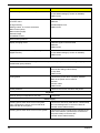
Revision History
Please refer to the table below for the updates made on this service guide.
Date
ii
Chapter
Updates
Copyright
Copyright © 2008 by Acer Incorporated. All rights reserved. No part of this publication may be reproduced,
transmitted, transcribed, stored in a retrieval system, or translated into any language or computer language, in
any form or by any means, electronic, mechanical, magnetic, optical, chemical, manual or otherwise, without
the prior written permission of Acer Incorporated.
iii
Disclaimer
The information in this guide is subject to change without notice.
Acer Incorporated makes no representations or warranties, either expressed or implied, with respect to the
contents hereof and specifically disclaims any warranties of merchantability or fitness for any particular
purpose. Any Acer Incorporated software described in this manual is sold or licensed "as is". Should the
programs prove defective following their purchase, the buyer (and not Acer Incorporated, its distributor, or its
dealer) assumes the entire cost of all necessary servicing, repair, and any incidental or consequential
damages resulting from any defect in the software.
Acer is a registered trademark of Acer Corporation.
Intel is a registered trademark of Intel Corporation.
Pentium Dual-Core, Celeron Dual-Core, Core 2 Duo, Core 2 Quad, Celeron, and combinations thereof, are
trademarks of Intel Corporation.
Other brand and product names are trademarks and/or registered trademarks of their respective holders.
iv
Conventions
The following conventions are used in this manual:
SCREEN
MESSAGES
Denotes actual messages that appear on screen.
NOTE
Gives additional information related to the current topic.
WARNING
Alerts you to any physical risk or system damage that might result from doing
or not doing specific actions.
CAUTION
Gives precautionary measures to avoid possible hardware or software
problems.
IMPORTANT
Reminds you to do specific actions relevant to the accomplishment of
procedures.
v
Service Guide Coverage
This Service Guide provides you with all technical information relating to the BASIC CONFIGURATION
decided for Acer's "global" product offering. To better fit local market requirements and enhance product
competitiveness, your regional office MAY have decided to extend the functionality of a machine (e.g. add-on
card, modem, or extra memory capability). These LOCALIZED FEATURES will NOT be covered in this generic
service guide. In such cases, please contact your regional offices or the responsible personnel/channel to
provide you with further technical details.
FRU Information
Please note WHEN ORDERING FRU PARTS, that you should check the most up-to-date information available
on your regional web or channel. If, for whatever reason, a part number change is made, it will not be noted in
the printed Service Guide. For ACER-AUTHORIZED SERVICE PROVIDERS, your Acer office may have a
DIFFERENT part number code to those given in the FRU list of this printed Service Guide. You MUST use the
list provided by your regional Acer office to order FRU parts for repair and service of customer machines.
vi
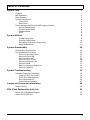
Table of Contents
System Tour
Features
M/B Placement
Block Diagram
System Components
Front Panel
Rear Panel
Power Management Function(ACPI support function)
Device Standby Mode
Global Standby Mode
Suspend Mode
ACPI
System Utilities
CMOS Setup Utility
Entering CMOS setup
Navigating Through the Setup Utility
Setup Utility Menus
System Disassembly
Disassembly Requirements
Pre-disassembly Procedure
Removing the Side Panel
Removing Front D/B
Removing CPU fan
Removing CPU Cooler
Removing wireless LAN
Removing M/B
Removing the Hard Disk Drive
Removing Memory
System Troubleshooting
Hardware Diagnostic Procedure
Power-On Self-Test (POST)
POST Error Messages List
Error Symptoms List
Undetermined Problems
Jumper and Connector Information
Jumper Setting
FRU (Field Replaceable Unit) List
Aspire R3610 Exploded Diagram
Aspire R3610 FRU List
1
1
4
5
6
6
7
8
8
8
8
8
9
9
10
10
11
24
24
25
26
27
28
29
30
31
32
33
34
34
34
40
42
47
48
48
56
57
58
vii
Chapter 1
System Tour
Features
Below is a brief summary of the computer’s many feature:
NOTE: The features listed in this section is for your reference only. The exact configuration of the system
depends on the model purchased.
Operating System
•
Microsoft Windows 7 Home Premium X64
•
Microsoft Windows 7 Home Premium X32 ( by request )
•
Microsoft Windows 7 Home Basic ( by request )
•
Linpus Linux X-windows version
•
Free Dos
Processor
Socket Type: None
•
Processor Type:
•
•
Intel Atom 330
•
TDP below 8W(include 8W)
Chipset
Single chip :Nvidia MCP7A-ION
•
PCB
170mm*170mm (Proprietary)
•
Memory subsystem
•
Memory Type: DDRII SO-DIMM 800
•
Single channel for 1 SO-DIMM SKU
•
Dual channel support for reserved 2 SO-DIMM SKU
•
DIMM Slot: 2
•
Capacity support:
•
512MB / 1GB / 2GB DDRII 800 SO-DIMM support
•
512MB to 4GB Max memory support
Design Criteria:
•
•
•
•
Should meet NV Chipset platform design guide
Dual channel should be enabled always when plug-in 2 same memory size DDRII memory
module
Should meet NV Chipsets Family BIOS Specification
Graphic solution
•
Chapter 1
NV MCP7A-ION on die graphic solution ( GF9400)
1
•
One D-sub port and One HDMI (Type-A) port
•
Dual View function support
•
Meet Microsoft Vista Premium graphic requirement
Hard disk
•
Support up to one SATA ports
•
2.5"
•
Capacity and models are listed on AVLC
Optical disk
•
None
Serial ATA controller
•
Slot Type: SATA connector
•
Slot Quantity: 1
•
Storage Type support: AHCI mode supported for internal SATA port
•
Slot Type :e-SATA connector :
One e-SATA support on front
•
Audio
•
Chip : Realtek ALC662
•
Connectors support:
Audio jacks color coding: should meet Microsoft Windows Logo Program Device Requirements:
Audio-0002
•
•
Front 2 jack follow HD audio definition
•
Add HD de-pop CKT
LAN
•
Controller: Realtek 8211CL
•
Port: 1 x RJ45 rear port for Gigabit Ethernet
USB ports
•
Controller: NV MCP7A-ION
•
4 back panel ports
•
2 ports for front daughter board
•
Connector Pin: standard Intel FPIO pin definition
•
USB 2.0/1.1Data transfer rate support
Extension slot
•
Support one Mini PCIe slot
Total I/O ports
2
•
One HDMI output in real I/O
•
One D-sub output in real I/O
•
Four USB in real I/O
•
One RJ45 in real I/O
Chapter 1
•
One DC-in jack in real I/O
•
One e-SATA port in front bezel
•
One HD headphone output in front bezel
•
One MIC-IN in front bezel
•
Tow USB in front bezel
•
One card reader ( 4 in 1: XD/SD/MMC/MS ) in front bezel
•
One S/PDIF port
System BIOS
•
BIOS Type: AMI Kernel with Acer skin
•
Size: 8Mb(depend on chipset BIOS programming guide)
Note:
•
•
Boot ROM should be included (PXE function should be built in with default and RPL function is
optional by service BIOS)
Adapter
•
Universal AC adapter, 90~264V AC, 47~63HZ
•
3-pin 65W with 19VDC output
•
Small DC jack
•
Energy Star5.0 support
Chapter 1
3
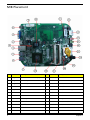
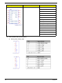
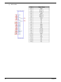
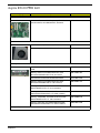
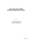
M/B Placement
No
Label
1
No
Label
Description
CLR_CMOS Clear CMOS header and jumper
13
ESATA
External SATA
2
Rear_USB2
Rear USB ports
14
MIC IN
Audio mic-in connector
3
Rear_USB1
Rear USB ports
15
Line out
Audio line-out connector
4
LAN CONN
Lan connector
16
Buzzer
Buzzer,Transductor,5V,40mA,2W,
5
SYS_FAN
System fan header
17
Card reader
CONN,Flash Memory Card
6
HDMI
HDMI connector
18
SPDIF
SPDIF header
7
VGA
VGA connector
19
Front Panel
Front Panel header
8
DCIN CONN 19V DC power in connector
20
BAT header
Battery header
9
MiniPCIE
miniPCIE connector
21
SODIMM1
CONN,DIMM,DDR II,SMD-200
10
CPU
IC,INTEL, Atom N330
22
SODIMM0
CONN,SO-DIMM,DDR II,SMD-200
11
SATA HDD
SATA HDD connector
23
MCP7A
IC,NVIDIA,MCP7A-ION-B2
12
SPI ROM
SPI ROM socket
4
Description
Chapter 1
Block Diagram
Chapter 1
5
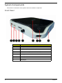
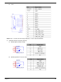
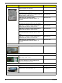
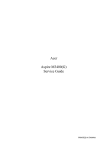
System Components
This section is a virtual tour of the system’s interior and exterior components.
Front Panel
6
No.
Component
1
e-SATA port
2
Microphone-in jack
3
Headphone/Speaker-out/line-out jack
4
Media card reader (4 in 1: XD/SD/MMC/MS)
5
SPDIF
6
Acer Logo
7
USB 2.0 port
8
Power Button
9
USB 2.0 port
Chapter 1
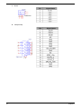
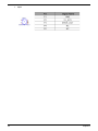
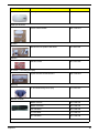
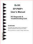
Rear Panel
No.
Chapter 1
Component
1
4 X USB 2.0 port
2
LAN Connector
3
HDMI Connector
4
D-sub Connector
5
DC-in Jack
7
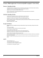
Power Management Function(ACPI support function)
Device Standby Mode
•
Independent power management timer for hard disk drive devices(0-15 minutes,time step=1minute).
•
Hard Disk drive goes into Standby mode(for ATA standard interface).
•
Disable V-sync to control the VESA DPMS monitor.
•
Resume method:device activated (keyboard for DOS, keyboard &mouse for Windows.
•
Resume recovery time 3-5sec.
Global Standby Mode
•
Global power management timer(2-120minutes,time step=10minute).
•
Hard disk drive goes into Standby mode(for ATA standard interface).
•
Disable H-sync and V-sync signals to control the VESA DPMS monitor.
•
•
Resume method: Resume to original state by pushing external switch Button,modem ring in,keyboard
an mouse for APM mode.
Resume recovery time :7-10sec
Suspend Mode
•
•
Independent power management timer(2-120minutes,time step=10minute)or pushing extern switch
button.
CPU goes into SMM
•
CPU asserts STPCLK# and goes into the Stop Grant State.
•
LED on panel turns amber colour.
•
Hard disk drive goes into SLEEP mode (for ATA standard interface).
•
Disable H-sync and V-sync signals to control the VESA DPMS monitor.
•
Ultra I/O and VGA chip go into power saving mode.
•
Resume method: Resume to original state by pushing external switch Button,modem ring in,keyboard
an mouse for APM mode
•
Return to original state by pushing external switch button,modem ring inand USB keyboard for ACPI
mode.
ACPI
8
•
ACPI specification 1.0b
•
S0,S1,S2 and S5 sleep state support.
•
On board device power management support.
•
On board device configuration support.
Chapter 1
Chapter 2
System Utilities
CMOS Setup Utility
CMOS setup is a hardware configuration program built into the system ROM, called the complementary metaloxide semiconductor (CMOS) Setup Utility. Since most systems are already properly configured and
optimized, there is no need to run this utility. You will need to run this utility under the following conditions.
q
When changing the system configuration settings
q
When redefining the communication ports to prevent any conflicts
q
When modifying the power management configuration
q
When changing the password or making other changes to the security setup
When a configuration error is detected by the system and you are prompted ("Run Setup"
message) to make changes to the CMOS setup
NOTE: If you repeatedly receive Run Setup messages, the battery may be bad. In this case, the system
cannot retain configuration values in CMOS. Ask a qualified technician for assistance.
q
CMOS setup loads the configuration values in a battery-backed nonvolatile memory called CMOS RAM. This
memory area is not part of the system RAM which allows configuration data to be retained when power is
turned off.
Before you run the CMOS Setup Utility, make sure that you have saved all open files. The system reboots
immediately after you close the Setup.
NOTE: CMOS Setup Utility will be simply referred to as “BIOS”, "Setup", or "Setup utility" in this guide.
The screenshots used in this guide display default system values. These values may not be the same
those found in your system.
Chapter 2
9
Entering CMOS setup
1.
Turn on the server and the monitor.
If the server is already turned on, close all open applications, then restart the server.
2.
During POST, press Delete.
If you fail to press Delete before POST is completed, you will need to restart the server.
The Setup Main menu will be displayed showing the Setup’s menu bar. Use the left and right arrow keys
to move between selections on the menu bar.
Navigating Through the Setup Utility
Use the following keys to move around the Setup utility.
q
Left and Right arrow keys – Move between selections on the menu bar.
q
Up and Down arrow keys – Move the cursor to the field you want.
q
PgUp and PgDn keys – Move the cursor to the previous and next page of a multiple page menu.
q
Home – Move the cursor to the first page of a multiple page menu.
q
End – Move the cursor to the last page of a multiple page menu.
+ and - keys – Select a value for the currently selected field (only if it is user-configurable). Press
these keys repeatedly to display each possible entry, or the Enter key to choose from a pop-up
menu.
NOTE: Grayed-out fields are not user-configurable.
q
q
Enter key – Display a submenu screen.
NOTE: Availability of submenu screen is indicated by a (>).
q
10
Esc – If you press this key:
q
On one of the primary menu screens, the Exit menu displays.
q
On a submenu screen, the previous screen displays.
q
When you are making selections from a pop-up menu, closes the pop-up without making a
selection.
q
F1 – Display the General Help panel.
q
F6 – Press to load optimized default system values.
q
F7 – Press to load fail-safe default system values.
q
F10 – Save changes made the Setup and close the utility.
Chapter 2
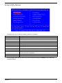
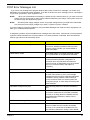
Setup Utility Menus
The Setup Main menu includes the following main setup categories.
Parameter
Description
Product Information
This page shows the relevant information of the main board
Standard CMOS Features
This setup page includes all the items in standard compatible BIOS
Advance BIOS Features CMOS
This setup page includes all the items of Award special enhanced features
Advanced Chipset Features
This setup page includes all advanced chipset features
Integrated Peripherals
This setup page includes all onboard peripherals
Power Management Setup
This setup page includes all the items of Green function features
PC Health Status
This setup page is the System auto detect Temperature, voltage, and fan speed
Frequency/Voltage Control
This setup page is the System Frequency setup
BIOS Security Features
Change, set or disable password. It allows you to limit access to the System
Load Default Setting
Load Default Setting indicates the value of the system parameters which the system would
be in best performance configuration
Save & Exit Setup
Save CMOS value settings to CMOS and exit setup
Exit Without Saving
Abandon all CMOS value changes and exit setup
In the descriptive table following each of the menu screenshots, settings in boldface are the default and
suggested settings.
Chapter 2
11
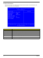
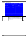
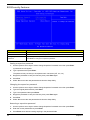
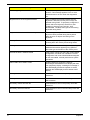
Product Information
The Product Information menu displays basic information about the system. These entries are for your
reference only and are not user-configurable.
Parameter
Description
Processor Type
Type of CPU installed on the system.
Processor Speed
Speed of the CPU installed on the system.
System Memory
Total size of system memory installed on the system.
Product Name
Product name of the system.
System Serial Number
Serial number of the system.
System BIOS Version
Version number of the BIOS setup utility.
BIOS Release Date
Date when the BIOS setup utility was released
Asset Tag Number
Asset tag number of this system.
12
Chapter 2
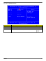
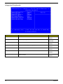
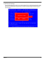
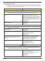
Standard CMOS Features
Parameter
Description
System Date
Set the date following the weekday-month-day-year format.
System Time
Set the system time following the hour-minute-second format.
AHCI Port 0/1
Press Enter to view detailed device information.
Halt On
Determines whether the system will stop for an error during the POST.
Option
All, But Keyboard
No Errors
All Errors
Chapter 2
13
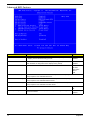
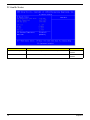
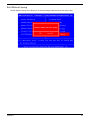
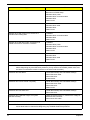
Advanced BIOS Feature
Parameter
Description
Option
Quick Boot
Allows you to decrease the time it takes to boot the computer by shortening
or skipping certain standard booting process.
Enabled
Quiet Boot
When enabled, the BIOS splash screen displays during startup.
Enabled
When disabled, the diagnostic screen displays during startup.
Disabled
Specifies the boot order from the available devices.
Hard Disk
1st/2nd/3rd/4th Boot Device
Disabled
CD^DVD
Removable
Device
LAN
Hard Disk Drive Priority
Press Enter to access the Hard Disk Drive Priority submenu and specify the boot device
priority sequence from available hard drives.
Optical Disk Drive Priority
Press Enter to access the Optical Disk Drive Priority submenu and specify the boot device
priority sequence from available CD/DVD drives.
Removable Device Priority
Press Enter to access the Removable Device Priority submenu and specify the boot device
priority sequence from available removable drives.
Boot up Num-Lock
Selects power on state for Num Lock.
USB Beep Message
Enables or disables BIOS to display error beeps or messages during USB
device enumeration.
On
Off
14
Disabled
Enabled
Chapter 2
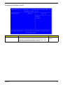
Advanced Chipset Features
Parameter
Description
Option
Intel XD Bit
When enabled, the processor disables code execution when a worm
attempts to insert a code in the buffer preventing damage and worm
propagation.
Enabled
Disabled
When disabled, the processor forces the Execute Disable (XD) Bit feature
flag to always return to 0.
Hyper Threading
Technology
Chapter 2
For Intel platform
Enabled
Disabled
15
Integrated Peripherals
Parameter
Description
Onboard SATA Controller
Enables or disables the onboard SATA controller.
Option
Enabled
Disabled
Onboard SATA Mode
Select an operating mode for the onboard SATA.
Onboard USB Controller
Enables or disables the onboard USB controller.
RAID
Native IDE
Enabled
Disabled
Legacy USB Support
Enables or disables support for legacy USB devices.
Onboard Audio Controller
Enables or disables the onboard audio controller.
Enabled
Disabled
Enabled
Disabled
Onboard LAN Controller
Enables or disables the onboard LAN controller.
Enabled
Disabled
Onboard LAN Option ROM
16
Enables or disables the load of embedded option ROM for onboard
network controller.
Enabled
Disabled
Chapter 2
Power Management Setup
Parameter
Description
Option
ACPI Suspend Mode
Select an ACPI state.
S3 (STR)
S1 (POS)
Deep Power off Mode
Enables or disables the Deep power off mode
Enabled
Disabled
Power On by RTC Alarm
Enables or disables to wake up the system by time setting
Enabled
Disabled
Power On by PCIE Devices
Enables or disables to wake up the system from a power saving mode
through an event on PCI Express device.
Enabled
Power On by Onboard Lan
Enables or Disables to wake up the system by Onboard Lan function
Enabled
Disabled
Disabled
Wake Up by USB KB/
Mouse
If enabled, press any key or click the mouse will wake system from S1/
S3 state.
Enabled
Restore On AC Power Loss
Enables or disables the system to reboot after a power failure or
interrupt occurs.
Power Off
Disabled
Power On
Last State
Chapter 2
17
PC Health Status
Parameter
Description
Option
CPU Shutdown Temperature
Enables or disables the system shutdown when the system is over hot.
Enabled
Smart FAN
Enables or disables the smart system fan control function.
Disabled
Enabled
Disabled
18
Chapter 2
Frequency/Voltage Control
Parameter
Spread Spectrum
Chapter 2
Description
Option
Enables or disables the reduction of the mainboard’s EMI.
Enabled
Note: Remember to disable the Spread Spectrum feature if you are
overclocking. A slight jitter can introduce a temporary boost in clock
speed causing the overclocked processor to lock up.
Disabled
19
BIOS Security Features
Parameter
Description
Supervisor Password
Indicates the status of the supervisor password.
User Password
Indicates the status of the user password.
Change Supervisor
Password
Supervisor password prevents unauthorized access to the BIOS Setup Utility.
Press Enter to change the Supervisor password.
Setting a supervisor password
1.
Use the up/down arrow keys to select Change Supervisor Password menu then press Enter.
A password box will appear.
2.
Type a password then press Enter.
The password may consist up to six alphanumeric characters (A-Z, a-z, 0-9)
3.
Retype the password to verify the first entry then press Enter again.
4.
Press F10.
5.
Select Yes to save the new password and close the Setup Utility.
Changing the supervisor password
1.
Use the up/down arrow keys to select Change Supervisor Password menu then press Enter.
2.
Type the original password then press Enter.
3.
Type a new password then press Enter.
4.
Retype the password to verify the first entry then press Enter again.
5.
Press F10.
6.
Select Yes to save the new password and close the Setup Utility.
Removing a supervisor password
20
1.
Use the up/down arrow keys to select Change Supervisor Password menu then press Enter.
2.
Enter the current password then press Enter.
3.
Press Enter twice without entering anything in the password fields.
Chapter 2
Load Default Settings
The Load Default Settings menu allows you to load the default settings for all BIOS setup parameters. Setup
defaults are quite demanding in terms of resources consumption. If you are using low-speed memory chips or
other kinds of low-performance components and you choose to load these settings, the system might not
function properly.
Chapter 2
21
Save & Exit Setup
The Save & Exit Setup menu allows you to save changes made and close the Setup Utility.
22
Chapter 2
Exit Without Saving
The Exit Without Saving menu allows you to discard changes made and close the Setup Utility.
Chapter 2
23
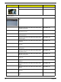
Chapter 3
System Disassembly
This chapter contains step-by-step procedures on how to disassemble the desktop computer for maintenance
and troubleshooting.
Disassembly Requirements
To disassemble the computer, you need the following tools:
q
Wrist grounding strap and conductive mat for preventing electrostatic discharge
q
Flat-blade screwdriver
q
Philips screwdriver
q
Hex screwdriver
q
Plastic flat-blade screwdriver
q
Plastic tweezers
NOTE: The screws for the different components vary in size. During the disassembly process, group the
screws with the corresponding components to avoid mismatch when putting back the components.
Chapter 3
24
Pre-disassembly Procedure
Before proceeding with the disassembly procedure, perform the steps listed below:
25
1.
Turn off the system and all the peripherals connected to it.
2.
Unplug the power cord from the power outlets.
3.
Unplug the power cord from the system.
4.
Unplug all peripheral cables from the system.
5.
Place the system unit on a flat, stable surface.
Chapter 3
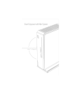
Removing the Side Panel
1.
Put the Computer on the worktable lightly.
2.
Release side cover with 1 screws then remove side cover.
Chapter 3
26
Removing Front D/B
27
1.
Use hand to loosen both sides the clasp.
2.
Lift the D/B away from the main board.
Chapter 3
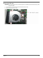
Removing CPU fan
WARNING:The heat sink becomes very hot when the system is on. NEVER touch the heat sink with any metal
or with your hands.
1.
Use screwdriver to loosen the three screws and disconnect fan cable.
2.
Remove CPU fan from CPU cooler.
Chapter 3
28
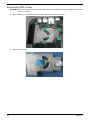
Removing CPU Cooler
WARNING:The heat sink becomes very hot when the system is on. NEVER touch the heat sink with any metal
or with your hands.
29
1.
Use screwdriver to loosen the four screws.Remove CPU fan from CPU cooler.
2.
Remove CPU cooler.
Chapter 3
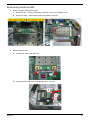
Removing wireless LAN
1.
2.
Remove wireless LAN antenna cable
a.
Disconnect aux_ antenna cable (gray) from"AUX" connector of wireless LAN?
b.
Disconnect main_ antenna cable (black) from"MAIN" connector.
Remove wireless LAN.
a.
Use hand to loosen both sides clip
b.
take off wireless LAN card from M/B MINI-PCIE" connector.
Chapter 3
30
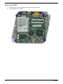
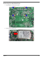
Removing M/B
31
1.
Remove the four screws that secure the main board to the chassis.
2.
Lift the board from the chassis.
Chapter 3
Removing the Hard Disk Drive
1.
Use screwdriver to loosen the four screws.
2.
Remove HDD from Main board.
Chapter 3
32
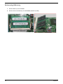
Removing Memory
.
33
1.
Remove Memory from SODIMM.
2.
Remove the second Memory from SODIMM2 (Optional by SKU).
Chapter 3
Chapter 4
System Troubleshooting
This chapter provides instructions on how to troubleshoot system hardware problems.
Hardware Diagnostic Procedure
Please refer to generic troubleshooting guide for troubleshooting information relating to following topics:
q
Power-On Self-Test (POST)
q
POST Error Messages List
q
Error Symptoms List
q
Undetermined Problems
Power-On Self-Test (POST)
Each time you turn on the system, the Power-on Self Test (POST) is initiated. Several items are tested during
POST, but is for the most part transparent to the user.
The Power-On Self Test (POST) is a BIOS procedure that boots the system, initializes and diagnoses the
system components, and controls the operation of the power-on password option. If POST discovers errors in
system operations at power-on, it displays error messages on screen, generates a check point code at port
80h or even halts the system if the error is fatal.
The main components on the main board that must be diagnosed and/or initialized by POST to ensure system
functionality are as follows:
q
Microprocessor with built-in numeric co-processor and cache memory subsystem
q
Direct Memory Access (DMA) controller
q
Interrupt system
q
Three programmable timers
q
ROM subsystem
q
RAM subsystem
q
CMOS RAM subsystem and real time clock/calendar with battery backup
q
Onboard parallel interface controller
q
Embedded hard disk interface and one diskette drive interface
q
Keyboard and auxiliary device controllers
q
1.44M floppy controller
q
I/O ports
q
One parallel port
q
One PS/2-compatible mouse port
One PS/2-compatible keyboard port
NOTE: When Post executes a task, it uses a series of preset numbers called check points to belatched atport
80h, indicating the stages it is currently running. This latch can be read and shown on a debug
board.The following table describes the BIOS common tasks carried out by POST. Each task is denoted
by an unique check point number. For other unique check point numbers that are not listed in the table,
refer to the corresponding product service guide.
q
Chapter 4
34
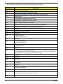
Post Checkpoints List: The list may vary accordingly depending on your BIOS
Checkpoint
Description
CFh
Test CMOS R/W functionality
C0h
Early chipset initialization: -Disable shadow RAM
-Disable L2 cache (socket 7 or below) -Program basic chipset registers
C1h
Detect memory
-Auto-detection of DRAM size, type and ECC.
-Auto-detection of L2 cache (socket 7 or below)
C3h
Expand compressed BIOS code to DRAM
C5h
Call chipset hook to copy BIOS back to E000 & F000 shadow RAM.
01h
Expand the Xgroup codes locating in physical address 1000:0
02h
Reserved
03h
Initial Superio_Early _Init switch
04h
Reserved
05h
1. Blank out screen
2. Clear CMOS error flag
06h
Reserved
07h
1. Clear 8042 interface
2. Initialize 8042 self-test
08h
1. Test special keyboard controller for Winbond 977 series Super I/O chips. 2. Enable
keyboard interface.
09h
Reserved
0Ah
1. Disable PS/2 mouse interface (optional)
2. Auto detect ports for keyboard & mouse followed by a port & interface swap (optional).
3. Reset keyboard for Winbond 977 series Super I/Q chips.
0Bh
Reserved
0Ch
Reserved
0Dh
Reserved
0Eh
Test F000h segment shadow to see whether it is R/W-able or not. If test fails, keep beeping
the speaker.
0Fh
Reserved
10h
Auto detect flash type to load appropriate flash R/W codes into the run time area in F000
for ESCD & DMI support.
11h
Reserved
12h
Use walking 1??s algorithm to check out interface in CMOS circuitry. Also set real-time
clock power status, and then check for override.
13h
Reserved
35
Chapter 4
Checkpoint
Description
14h
Program chipset default values into chipset. Chipset default values are MODBINable by
OEM customers.
15h
Reserved
16h
Initial Early_Init_Onboard_Generator switch.
17h
Reserved
18h
Detect CPU information including brand, SMI type (Cyrix or Intel) and CPU level (586 or
686)
19h
Reserved
1Ah
Reserved
1Bh
Initial interrupts vector table. If no special specified, all H/W interrupts are directed to
SPURIOUS_INT_HDLR & S/W interrupts to PURIOUS_soft_HDLR.
1Ch
Reserved
1Dh
Initial Early_PM_INIT switch.
1Eh
Reserved
1Fh
Load keyboard matrix (notebook platform)
20h
Reserved
21h
HPM initialization (notebook platform)
22h
Reserved
3Ch
Test 8254.
3Dh
Reserved
3Eh
Test 8259 interrupt mask bits for channel 1
3Fh
Reserved
40h
Test 8259 interrupt mask bits for channel 2
41h
Reserved
42h
Reserved
43h
Test 8259 functionality
44h
Reserved
45h
Reserved
46h
Reserved
47h
Initialize EISA slot
48h
Reserved
49h
1. Calculate total memory by testing the last double word of each 64K.
2. Program writes allocation for AMD K5 CPU.
4Ah
Reserved
4Bh
Reserved
Chapter 4
36
Checkpoint
Description
4Ch
Reserved
4Dh
Reserved
4Eh
1. Program MTRR of M1 CPU.
2. Initialize L2 cache for P6 class CPU & program CPU with proper cacheable range.
3. Initialize the APIC for P6 class CPU.
4. On MP platform, adjust the cacheable range to smaller one in case the cacheable
ranges between each CPU are not identical.
4Fh
Reserved
50h
Initialize USB
51h
Reserved
52h
Test all memory (clear all extended memory to 0)
53h
Reserved
54h
Reserved
55h
Display number of processors (multi-processor platform)
56h
Reserved
57h
1. Display PnP logo
2. Early ISA PnP initialization -Assign CSN to every ISA PnP device.
58h
Reserved
59h
Initialize the combined Trend Anti-Virus code.
5Ah
Reserved
5Bh
(Optional Feature) Show message for entering AWDFLASH.EXE from FDD (optional)
5Ch
Reserved
5Dh
1. Initialize Init_Onboard_Super_IO switch.
2. Initialize Init_Onboard_AUDIO switch.
5Eh
Reserved
5Fh
Reserved
60h
Okay to enter Setup utility; i.e. not until this POST stage can users enter the CMOS setup
utility.
61h
Reserved
62h
Reserved
63h
Reserved
64h
Reserved
65h
Initialize PS/2 Mouse
66h
Reserved
67h
Prepare memory size information for function call: INT 15h ax=E820h
68h
Reserved
37
Chapter 4
Checkpoint
Description
69h
Turn on L2 cache
6Ah
Reserved
6Bh
Program chipset registers according to items described in Setup& Auto configuration table.
6Ch
Reserved
6Dh
1. Assign resources to all ISA PnP devices.
2. Auto assign ports to onboard COM ports if the corresponding item in Setup is set to
“AUTO”
6Eh
Reserved
6Fh
1. Initialize floppy controller
2. Set up floppy related fields in 40: hardware.
70h
Reserved
71h
Reserved
72h
Reserved
73h
(Optional Feature) Enter AWDFLASH.EXE if:
-AWDFLASH is found in floppy drive
-ALT+F2 is pressed
74h
Reserved
75h
Detect & install all IDE devices: HDD, LS120, ZIP,CDROM....
76h
Reserved
77h
Detect serial ports & parallel ports
78h
Reserved
79h
Reserved
7Ah
Detect & install co-processor
7Bh
Reserved
7Ch
Reserved
7Dh
Reserved
7Eh
Reserved
7Fh
1. Switch back to text mode if full screen logo is supported.
-If errors occur, report errors & wait for keys
-If no errors occur or F1 key is pressed to continue: Clear EPA or customization logo.
80h
Reserved
81h
Reserved
82h
1. Call chipset power management hook.
2. Recover the text fond used by EPA logo (not for full screen logo)
3. If password is set, ask for password.
83h
Save all data in stack back to CMOS.
84h
Initialize ISA PnP boot devices.
Chapter 4
38
Checkpoint
Description
85h
1. USB final Initialization
2. NET PC: Build SYSID structure
3. Switch screen back to text mode.
4. Set up ACPI table at top of memory.
5. Invoke ISA adapter ROMs.
6. Assign IRQs to PCI devices
7. Initialize APM
8. Clear noise of IRQs
86h
Reserved
87h
Reserved
88h
Reserved
89h
Reserved
90h
Reserved
91h
Reserved
92h
Reserved
93h
Read HDD boot sector information for Trend Anti-Virus code
94h
1. Enable L2 cache
2. Program boot up speed
3. Chipset final initialization
4. Power management final initialization
5. Clear screen & display summary table
6. Program K6 write allocation
7 Program P6 class write combining.
95h
1. Program daylight saving
2. Update keyboard LED & typematic rate
96h
1. Build MP table
2. Build & update ESCD
3. Set CMOS century to 20h or 19h
4. Load CMOS time into DOS timer tick
5. Build MSIRQ routing table
FFh
Boot attempt (INT 19h)
39
Chapter 4
POST Error Messages List
If you cannot run the diagnostics program tests but did receive a POST error message, use "POST Error
Messages List" to diagnose system problems. If you did not receive any error message, look for a description
of your error symptoms in "Error Symptoms List"
NOTE:
When you have deemed it necessary to replace an FRU, and have done so, you must run a total
system check to ensure that no other activity has been affected by the change. This system check can
be done through the diagnostics program.
NOTE:
Check all power supply voltages, switch, and jumper settings before you replace the main board.
Also check the power supply voltages if you have a "system no-power" condition.
If you are unable to correct the problem by using the "BIOS Messages List" table and "Error Symptoms List"
table, go to "Undetermined Problems".
To diagnose a problem, first find the BIOS error messages in the left column. If directed to a check procedure,
replace the FRU indicated in the check procedure. If no check procedure is indicated, the first Action/FRU
listed in right column is the most likely cause.
BIOS Messages
Action/FRU
BIOS ROM checksum error - System halted
The checksum of the BIOS code in the BIOS chip
is incorrect, indicating the BIOS code may have
become corrupt. Contact your system dealer to
replace the BIOS.
CMOS Battery Failed
The CMOS battery is no longer functional. Contact
your system dealer for a replacement the BIOS.
CMOS Checksum Error- defaults loaded
Checksum of CMOS is incorrect, so the system
loads the default equipment configuration. A
checksum error may indicate that CMOS has
become corrupt. A weak battery may have caused
this error. Check the battery and replace if
necessary.
CPU at nnnn
Displays the running speed of CPU.
Display switch is set incorrectly
The display switch on the motherboard can be set
to either monochrome or color. This message
indicates the switch is set to a different setting than
indicated in Setup. Determine which setting is
correct, and then either turn off the system and
change the jumper, or enter Setup and change the
Video selection.
Press ESC to skip memory test
The user may press Esc to skip the full memory
test.
Floppy disk(s) fail
Cannot find or initialize the floppy drive controller
or the drive. Make sure the controller is installed
correctly, if no floppy drives are installed, be sure
the Diskette Drive selection in Setup is set to
NONE or AUTO.
HARD DISK initializing - Please wait a moment
Some hard drives require extra time to initialize.
HARD DISK INSTALL FAILURE
Cannot find or initialize the hard drive controller or
the drive. Make sure the controller is installed
correctly. If no hard drives are installed, be sure
the Hard Drive Selection in Setup is set to NONE.
Chapter 4
40
BIOS Messages
41
Action/FRU
Hard disk(s) diagnosis fail
The system may run specific disk diagnostic
routines. This message appears if one or more
hard disks return an error when the diagnostics
run.
Keyboard Error Or No Keyboard Present
Cannot initialize the keyboard. Make sure the
keyboard is attached correctly and no keys are
pressed during POST. To purposely configure the
system without a keyboard, set the error halt
condition in Setup to HALT ON ALL, BUT
KEYBOARD. The BIOS then ignores the missing
keyboard during POST.
Keyboard is locked out - Unlock the key
This message usually indicates that one or more
keys have been pressed during the keyboard
tests. Be sure no objects are resting on the
keyboard.
Memory Test:
This message displays during a full memory test,
counting down the memory areas being tested.
Memory test fail
If POST detects an error during memory testing,
additional information appears giving specifics
about the type and location of the memory error.
Override enabled - Defaults loaded
If the system cannot boot using the current CMOS
configuration, the BIOS can override the current
configuration with a set of BIOS defaults designed
for the most stable, minimal-performance system
operations.
Press TAB to show POST screen
System OEMs may replace the Phoenix
Technologies Award BIOS POST display with their
own proprietary display. Including this message in
the OEM display permits the operator to switch
between the OEM display and the default POST
display.
Primary master hard disk fail
POST detects an error in the primary master IDE
hard drive.
Primary slave hard disk fail
POST detects an error in the secondary master
IDE hard drive.
Secondary master hard disk fail
POST detects an error in the primary slave IDE
hard drive.
Secondary slave hard disk fail
POST detects an error in the secondary slave IDE
hard drive.
Chapter 4
Error Symptoms List
NOTE: To diagnose a problem, first find the error symptom in the left column. If directed to a check procedure,
replace the FRU indicated in the check procedure. If no check procedure is indicated, the first Action/
FRU listed in right column is the most likely cause.
Error Symptom
Action/FRU
Processor / Processor Fan
NOTE: Normally, the processor fan should be operative, and the processor clock setting should be
exactly set to match its speed requirement before diagnosing any processor problems.
Processor fan does not run but power supply fan
runs.
1. Ensure the system is not in power saving
mode.See “Power Management”in chapter2.
2.With the system power on, measure the voltage of
processor fan connector. Its reading should be
+12Vdc. Its reading should be +12Vdc. If the reading
shows normal, but the fan still does not work, then
replace a good fan.
3. Main board.
Processor test failed.
1.Processor.
2.Main board.
Main board and Memory
NOTE: Ensure the memory modules are installed properly and the contact leads are clean before
diagnosing any system problems.
Memory test failed.
1.See "Memory"
2.Main board
Incorrect memory size shown or repeated during
POST.
1.Insert the memory modules in the DIMM sockets
properly, then reboot the system.
2.Memory module.
3.Main board.
System works but fails to enter power saving mode
when the Power Management Mode is set to
Enabled.
1.Enter BIOS Setup and load default settings.In
Windows Systems, check settings in Power
Management Property of Control Panel.
2.Reload software from Recovery CD.
Blinking cursor only; system does not work.
1.Diskette/IDE drive connection/cables
2. Diskette/IDE disk drives
3.See “Undetermined Problems”.
4.Main board
Diskette Drive
NOTE: Ensure the diskette drive is auto-setting in BIOS Setup and its read/write head is clean before
diagnosing any diskette drive problems.(If only one drive is installed, please make sure the drive is
connected to master connector or the drive is set to master.)
Media and drive are mismatched.
Chapter 4
1.Ensure the diskette drive is configured correctly in
the Disk Drives of BIOS Setup.
2.Ensure the diskette drive is correctly formatted.
3.Diskette drive connection/cable
4.Diskette drive
5.Main board
42
Error Symptom
Action/FRU
Diskette drive does not work.
1.Ensure the diskette drive is not set to None in the
Disk Drives of BIOS Setup.
2.Diskette drive power
3.Diskette drive connection/cable
4.Diskette drive
5.Main board
Diskette drive read/write error.
1.Diskette.
2.Diskette drive cable.
3.Diskette drive.
4.Main board
Diskette drive LED comes on for more than 2
minutes when reading data.
1.Diskette
2.Diskette drive connection/cable
3.Diskette drive
4.Main board
Diskette drive LED fails to light, and the drive is
unable to access for more than 2 minutes.
1.Diskette
2.Diskette drive power
3.Diskette drive connection/cable
4.Diskette drive
5.Main board
Diskette drive test failed.
1.Diskette
2.Diskette drive
3.Diskette drive cable
4.Main board
Hard Disk Drive
NOTE: Ensure hard disk drive is configured correctly in BIOS Setup, cable/jumper are set correctly
before diagnosing any hard disk drive problems. (If only one drive is installed, please make sure
the drive is connected to master connector or the drive is set to master.)
Hard disk drive test failed.
1.Enter BIOS Setup and Load default settings.
2.Hard disk drive cable.
3.Hard disk drive.
4. Main board.
Hard disk drive cannot format completely.
1.Enter BIOS Setup and Load default settings.
2.Hard disk drive cable.
3.Hard disk drive.
4.Main board
Hard disk drive has write error.
1.Enter BIOS Setup and Load default settings.
2.Hard disk drive.
Hard disk drive LED fails to light, but system
operates normally.
1.With the system power on, measure the voltage of
hard disk LED connector.
2.Hard drive LED cable.
CD/DVD-ROM Drive
NOTE: Ensure CD/DVD-ROM drive is configured correctly in BIOS Setup, cable/jumper are set correctly
and its laser beam is clean before diagnosing any CD/DVD-ROM drive problems.
43
Chapter 4
Error Symptom
Action/FRU
CD/DVD-ROM drive LED doesn't come on but works
normally.
1.CD/DVD-ROM drive
CD/DVD-ROM drive LED flashes for more than 30
seconds before LED shutting off.
Software asks to reinstall disc.Software displays a
reading CD/DVD error.
1.CD/DVD-ROM may have dirt or foreign material on
it. Check with a known good disc.
2. CD/DVD-ROM is not inserted properly.
3.CD/DVD-ROM is damaged.
CD/DVD-ROM drive cannot load or eject when the
system is turned on and its eject button is pressed
and held.
1.Disconnect all cables from CD/DVD-ROM drive
except power cable, then press eject button to try to
unload the disk.
2.CD/DVD-ROM drive power.
3.CD/DVD-ROM drive
CD/DVD-ROM drive does not read and there are no
messages are displayed.
1.CD may have dirt or foreign material on it. Check
with a known good disc.
2.Ensure the CD/DVD-ROM driver is installed
properly.
3.CD/DVD-ROM drive.
CD/DVD-ROM drive can play audio CD but no
sound output.
1.Ensure the headphone jack of the CD/DVD-ROM
has an output.
2.Turn up the sound volume.
3.Speaker power/connection/cable.
4.CD/DVD-ROM drive.
Real-time clock
Real-time clock is inaccurate.
1.Ensure the information in the Standard CMOS
Feature of BIOS Setup is set correctly.
2.RTC battery.
3.Main board.
Audio
Audio software program invokes but no sound
comes from speakers.
1.Speaker power/connection/cable.
Modem
Modem ring cannot wake up system from suspend
mode.
1.For the External Modem, make sure Power on By
Ring in BIOS Setup or Power Management is set to
Enabled. For the PCI modem, make sure Wake up
by PCI card is set to Enabled.
2.If PCI modem card is used, reinsert the modem
card to PCI slot firmly or replace the modem card.
3.In Win 98, ensure the telephone application is
configured correctly for your modem and set to
receive messages and/or fax.
Data/fax modem software program invokes but
cannot receive/send data/fax
1.Ensure the modem card is installed properly.
Fax/voice modem software program invokes but has
no sound output. (Data files are received normally;
voice from modem cannot be produced, but system
sound feature works normally.)
1.Ensure the modem voice-in cable from modem
adapter card to main board
Video and Monitor
Chapter 4
44
Error Symptom
Action/FRU
Video memory test failed.Video adapter failed.
1.Remove all non-factory-installed cards.
2.Load default settings (if screen is readable).
3.Main board
Display problem:
-Incorrect colors
No high intensity
Missing, broken, or incorrect characters
Blank monitor (dark)
Blank monitor (bright)
Distorted image
Unreadable monitor
1.Monitor signal connection/cable.
2.Monitor
3.Video adapter card
4.Main board
Other monitor problems
Display changing colors.
1.Monitor signal connection/cable
2.Monitor
3.Main board
Display problem not listed above (including blank or
illegible monitor).
1.”Monitor"
2.Load default settings (if screen is readable).
3.Main board
Parallel/Serial Ports
Execute “Load BIOS Default Settings” in BIOS Setup to confirm ports presence before diagnosing any
parallel/serial ports problems.
Serial or parallel port loop-back test failed.
1.Make sure that the LPT# or COM# you test is the
same as the setting in BIOS Setup.
2.Loop-back.
3.Main board
Printing failed.
1.Ensure the printer driver is properly installed.
Refer to the printer service manual.
2.Printer.
3.Printer cable.
4.Main board.
Printer problems.
1.Refer to the service manual for the printer.
Keyboard
Some or all keys on keyboard do not work.
1.Keyboard
Power Supply
Pressing power switch does not turn off system.
(Only unplugging the power cord from electrical
outlet can turn off the system.)
1.Ensure the Soft-off by PWR-BTTN. in BIOS Setup
of Power Management is not set to Instant-off.
2.Power switch cable assembly
Pressing power switch does not turn on the system.
1.Ensure the power override switch (situated at the
back of the machine, just above the connector for
the power cable) is not set to OFF.
2.Power switch cable assembly.
45
Chapter 4
Error Symptom
Action/FRU
Executing software shutdown from Windows98 Start
menu does not turn off the system. (Only pressing
power switch can turn off the system).
1.Load default settings.
2.Reload software from Recovery CD.
No system power, or power supply fan is not
running.
1.Power Supply
2.Main board
Other Problems
Any other problems.
Chapter 4
1.Undetermined Problems
46
Undetermined Problems
If an error message is present, go to "POST Error Messages List" on page 85. If you did not receive any
messages, if the symptom is listed in "or "Error Symptoms List" on page 87. If you still cannot solve the
problem, continue with this check:
1.
Check the power supply voltage. If the voltage are correct continue with the following steps:
2.
Power off the system unit.
3.
Perform the following checks, one by one, until you have isolated the problem FRU.
4.
Load default settings in setup.
5.
Check all main board jumper positions and switch settings.
6.
Check all adapter card jumper positions.
7.
Check all device jumper positions.
8.
Check all cables and connectors for proper installation.
9.
If the jumpers, switches and voltage settings are correct, remove or disconnect the following, one at a
time:
10. Non-Acer devices
q
External devices
q
Any adapter card (modem card, LAN card or video card, if installed)
q
CD/DVD-ROM drive
q
Diskette drive
q
Hard disk drive
q
DIMM
q
Processor
q
Main board
11. Power on the system unit.
12. Repeat steps 2 through 5 until you find the failing device or adapter.
47
Chapter 4
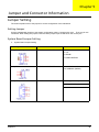
Chapter 5
Jumper and Connector Information
Jumper Setting
The section explains how to set jumper for correct configuration of the mainboard.
Setting Jumper
Use the motherboard jumpers to set system configuration options. Jumpers with more Than one pin are
numbered. When setting the jumpers, ensure that the jumper caps are Placed on the correct pins.
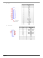
System Board Jumper Setting
1.
System Board Jumper Setting
Jumper/Header Name
Function
Definition
SYS_FAN (4 PIN)
SYSTEM FAN HEADER
1: GND
2: +5V
3: SENSE
4. PWM CONTROL
CLR_CMOS
CLEAR CMOS HEADER
1-2: CLEAR CMOS
2-3: NORMAL (Default)
BAT1(3 PIN)
BATTERY HEADER
1: Battery power output
2: RTC_SENSE#
3-5: GND
Chapter 5
48
Jumper/Header Name
FP1
Function
Front panel header
Definition
1: GND
2: F_USBPWR
3: USB_P5+
4: USB_P55: GND
6: F_USBPWR*
7: USB_P4+
8: USB_P49: FP_9(PU 5V_S0)
10: KEY
11: PWRBTNJ
12: LEDP
13: GND
14: PMSLED
2.
USB CONNECTORS (Stacked)(Black)
a.
49
REAR_USB1, REAR_USB2
Chapter 5
b.
LAN1
NOTE: Pins 1-12 for RJ-45 LAN Jack pin definition, 13-16 for LAN LED definition
3.
Audio Back Panel Connectors (Vertical)
a.
AUDIO1 (MIC IN /Pink in Color)
b.
AUDIO2 (LINE OUT /Lime in Color)
Chapter 5
50
51
c.
DCIN
d.
VGA(D-SUB)
Chapter 5
e.
HDMI
f.
eSATA CONN
Chapter 5
52
g.
53
SATA CONN
Chapter 5
h.
Chapter 5
Card reader
Pin
SD-1
SD-2
Signal Name
SD_DAT3
SD_CMD
Pin
MS-10
G1
Signal Name
GND
GND
SD-3
GND
G2
GND
SD-4
CARD_3V3
XD-1
GND
SD-5
SD_CLK
XD-2
XD_CD#
SD-6
GND
XD-3
XD_RDY
SD-7
MS_SD_DAT0
XD-4
XD_RE#
SD-8
SD_DAT1
XD-5
XD_CE#
SD-9
SD_DAT2
XD-6
XD_CLE
SD-CD1 GND
XD-7
XD_ALE
SD-CD2 SD_CD#
XD-8
XD_W E#
SD-W P1 GND
SD-W P2 SD_W P
XD-9
XD-10
XD_W P#
GND
MS-1
GND
XD-11
XD_D0
MS-2
MS_BS
XD-12
XD_D1
MS-3
MS_D1
XD-13
XD_D2
MS-4
MS_SD_DAT0
XD-14
XD_D3
MS-5
MS_D2
XD-15
XD_D4
MS-6
MS_INS#
XD-16
XD_D5
MS-7
MS_D3
XD-17
XD_D6
MS-8
CR_CLK
XD-18
XD_D7
MS-9
CARD_3V3
XD-19
CARD_3V3
54
i.
55
Spidif
Chapter 5
Chapter 6
FRU (Field Replaceable Unit) List
This chapter offers the FRU (Field Replaceable Unit) list in global configuration of the Aspire R3610 desktop
computer. Refer to this chapter whenever ordering the parts to repair or for RMA (Return Merchandise
Authorization).
NOTES:
Chapter 6
q
When ordering FRU parts, check the most up-to-date information available on your regional web
or channel. For whatever reasons a part number is changed, it will NOT be noted on the printed
Service Guide. For Acer authorized service providers, your Acer office may have a different part
number code from those given in the FRU list of this printed Service Guide. You MUST use the
local FRU list provided by your regional Acer office to order FRU parts for service.
q
To scrap or to return the defective parts, follow the local government ordinance or regulations on
how to dispose it properly, or follow the rules set by your regional Acer office on how to return it.
q
This document will be updated as more information about the FRU list becomes available.
56
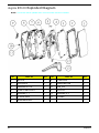
Aspire R3610 Exploded Diagram
NOTE: This section will be updated when more information becomes available.
NO
57
PART NO
QTY
NO
PART NO
QTY
1
Bot-cover
1
8
01-Main-base
1
2
Cover-pannel
1
9
POWER-BUTTON
1
3
SHEETMETAL-TOP
1
10
2009_Acer
1
4
ACER-1L-MB-LOYOUT
1
11
Top-Cover
1
5
ANTENNA_P_7
1
12
ANTENNA_B_8
1
6
1L-Power-Switch
1
13
V-STAND
1
7
SHEETMETAL-BOT
1
Chapter 6
Aspire R3610 FRU List
Category
Description
Part Number
MB
Mainboard R3610 nVidia Proprietary LF MCP7AION,W/ eSATA, W/ HDMI,S/PDIF ,Atom330
MB.SCX09.001
w/i 7012 blower (for Atom 230)
HI.10800.038
Hornet a/p/g N330 FXN PKP710G w/i sunon fan
HI.10800.043
so-DIMM GU331G0ALEPR612C6CE/DDRII800/
1GB
KN.1GB0H.010
Memory NANYA SO-DIMM DDRII 800 1GB
NT1GT64UH8D0FN-AD LF 64*16 0.07um
KN.1GB03.025
GU332G0ALEPR8H2C6CE/DDRII800/2GB
KN.2GB0H.003
Memory NANYA SO-DIMM DDRII 800 2GB
NT2GT64U8HD0BN-AD LF 128*8 0.07um
KN.2GB03.010
Memory SAMSUNG SO-DIMM DDRII 800 1GB
M470T2864EH3-CF7 LF 64*16 0.055um
KN.1GB0B.033
Memory UNIFOSA SO-DIMM DDRII 800 1GB
GU331G0ALEPR612C6F1 LF 128*8 0.065um
KN.1GB0H.014
Memory SAMSUNG SO-DIMM DDRII 800 2GB
M470T5663EH3-CF7 LF 128*8 0.055um
KN.2GB0B.018
Memory UNIFOSA SO-DIMM DDRII 800 2GB
GU332G0ALEPR8H2C6F1 LF 128*8 0.065um
KN.2GB0H.008
Cooler
Memory
HDD (SATA)
Chapter 6
58
Category
Description
Part Number
HGST 2.5" 5400rpm 160GB HTS543216L9A300
Falcon-B SATA LF F/W:C40C
KH.16007.019
SEAGATE 2.5" 5400rpm 160GB ST9160310AS
Crockett SATA LF F/W:0303
KH.16001.034
WD 2.5" 5400rpm 160GB WD1600BEVT-22ZCTO
ML160 SATA LF F/W:11.01A11
KH.16008.022
HDD HGST 2.5" 5400rpm 250GB
HTS545025B9A300 Panther B SATA LF F/
W:C60F
KH.25007.015
HDD SEAGATE 2.5" 5400rpm 250GB
ST9250315AS Wyatt SATA LF F/W:0001SDM1
KH.25001.016
HDD WD 2.5" 5400rpm 250GB WD2500BEVT22ZCT0 ML160 SATA LF F/W:11.01A11
KH.25008.021
HDD WD 2.5" 5400rpm 320GB WD3200BEVT22ZCT0 ML160 SATA LF F/W:11.01A11
KH.32008.013
HDD HGST 2.5" 5400rpm 320GB
HTS545032B9A300 Panther B SATA LF F/W:
C60F
KH.32007.007
HDD WD 2.5" 5400rpm 500GB WD5000BEVT22ZAT0 ML250 SATA LF F/W:01.01A01
KH.50008.013
HDD HGST 2.5" 5400rpm 500GB
HTS545050B9A300 Panther B SATA LF F/
W:C60F
KH.50007.009
VD56UL, Modem USB dongle 56K modem
FX.10100.001
Foxconn 802.11 b/g/n WLAN mini-card Atheros
XB91 (mini-card), 1Tx2R
NI.10200.012
Foxconn T60H976.11 Atheros XB63 WLAN
Foxconn T60H976.11 Atheros XB63 WLAN
Atheros PCI-Express WLAN 8
NI.10200.026
65W
AP.06501.026
65W (level 5) - HP-A0652R3B 2LF
AP.0650A.014
Modem
Wireless
Adapter
RF Mouse
59
Chapter 6
Category
Description
Part Number
Chicony Mouse RF2.4 MGR0919 with Receiver
MS.11200.052
mouse USB M-U0005
MS.11200.047
Neosonica mini speaker USB White
SP.10600.028
webcam+stand
PC.13400.035
USB Optical Mouse
Speaker
webcam
air mouse + controller(game pad)
Cywee 3D stick mouse Mouse Z
MS.11200.053
1L Hornet Mounting kit for a/p/g
PC.13400.041
EMEA Vista RC
RT.11300.009
EMEA Vista MCE
RT.11300.005
US Vista MCE
RT.11300.006
TC Vista MCE
RT.11300.007
SC Vista MCE
RT.11300.008
Mounting
Remote controller
receiver
Chapter 6
60
Category
Description
Part Number
Receiver w/o IR Blaster
RV.11000.007
Receiver w/ IR Blaster
RV.11000.014
Keyboard CHICONY KU-0906 USB 104KS White
US
KB.USB03.154
Keyboard CHICONY KU-0906 USB 104KS White
Traditional Chinese
KB.USB03.155
Keyboard CHICONY KU-0906 USB 104KS White
Simplified Chinese
KB.USB03.156
Keyboard CHICONY KU-0906 USB 104KS White
US International
KB.USB03.157
Keyboard CHICONY KU-0906 USB 104KS White
Arabic/English
KB.USB03.158
Keyboard CHICONY KU-0906 USB 104KS White
Thailand
KB.USB03.159
Keyboard CHICONY KU-0906 USB 105KS White
Spanish
KB.USB03.160
Keyboard CHICONY KU-0906 USB 105KS White
Portuguese
KB.USB03.161
Keyboard CHICONY KU-0906 USB 105KS White
Canadian French
KB.USB03.162
Keyboard CHICONY KU-0906 USB 105KS White
Brazilian Portuguese
KB.USB03.163
Keyboard CHICONY KU-0906 USB 109KS White
Japanese
KB.USB03.164
Keyboard CHICONY KU-0906 USB 105KS White
German
KB.USB03.165
Keyboard CHICONY KU-0906 USB 105KS White
Italian
KB.USB03.166
Keyboard CHICONY KU-0906 USB 105KS White
French
KB.USB03.167
Keyboard CHICONY KU-0906 USB 105KS White
Swedish
KB.USB03.168
Keyboard CHICONY KU-0906 USB 105KS White
UK
KB.USB03.169
USB Keyboard
61
Chapter 6
Category
Chapter 6
Description
Part Number
Keyboard CHICONY KU-0906 USB 105KS White
Dutch
KB.USB03.170
Keyboard CHICONY KU-0906 USB 105KS White
Swiss/G
KB.USB03.171
Keyboard CHICONY KU-0906 USB 105KS White
Belgium
KB.USB03.172
Keyboard CHICONY KU-0906 USB 105KS White
Icelandic
KB.USB03.173
Keyboard CHICONY KU-0906 USB 105KS White
Norwegian
KB.USB03.174
Keyboard CHICONY KU-0906 USB 104KS White
Hebrew
KB.USB03.175
Keyboard CHICONY KU-0906 USB 105KS White
Polish
KB.USB03.176
Keyboard CHICONY KU-0906 USB 105KS White
Slovenian
KB.USB03.177
Keyboard CHICONY KU-0906 USB 105KS White
Slovak
KB.USB03.178
Keyboard CHICONY KU-0906 USB 104KS White
Russian
KB.USB03.179
Keyboard CHICONY KU-0906 USB 105KS White
Hungarian
KB.USB03.180
Keyboard CHICONY KU-0906 USB 104KS White
Greek
KB.USB03.181
Keyboard CHICONY KU-0906 USB 105KS White
Danish
KB.USB03.182
Keyboard CHICONY KU-0906 USB 104KS White
Czech
KB.USB03.183
Keyboard CHICONY KU-0906 USB 105KS White
Romanian
KB.USB03.184
Keyboard CHICONY KU-0906 USB 105KS White
Turkish
KB.USB03.185
Keyboard CHICONY KU-0906 USB 105KS White
Spanish Latin
KB.USB03.186
Keyboard CHICONY KU-0906 USB 105KS White
Turkish-Q
KB.USB03.187
Keyboard CHICONY KU-0906 USB 105KS White
Arabic/French
KB.USB03.188
Keyboard CHICONY KU-0906 USB 104KS White
Kazakh
KB.USB03.189
Keyboard CHICONY KU-0906 USB 104KS White
Turkmen
KB.USB03.190
62
Category
Description
Part Number
Keyboard CHICONY KU-0906 USB 105KS White
Nordic
KB.USB03.191
Keyboard CHICONY KG-0917 RF2.4 104KS
White US
KB.RF403.097
Keyboard CHICONY KG-0917 RF2.4 104KS
White Traditional Chinese
KB.RF403.098
Keyboard CHICONY KG-0917 RF2.4 104KS
White Simplified Chinese
KB.RF403.099
Keyboard CHICONY KG-0917 RF2.4 104KS
White US International
KB.RF403.100
Keyboard CHICONY KG-0917 RF2.4 104KS
White Arabic/English
KB.RF403.101
Keyboard CHICONY KG-0917 RF2.4 104KS
White Thailand
KB.RF403.102
Keyboard CHICONY KG-0917 RF2.4 105KS
White Spanish
KB.RF403.103
Keyboard CHICONY KG-0917 RF2.4 105KS
White Portuguese
KB.RF403.104
Keyboard CHICONY KG-0917 RF2.4 105KS
White Canadian French
KB.RF403.105
Keyboard CHICONY KG-0917 RF2.4 107KS
White Brazilian Portuguese
KB.RF403.106
Keyboard CHICONY KG-0917 RF2.4 109KS
White Japanese
KB.RF403.107
Keyboard CHICONY KG-0917 RF2.4 105KS
White German
KB.RF403.108
Keyboard CHICONY KG-0917 RF2.4 105KS
White Italian
KB.RF403.109
Keyboard CHICONY KG-0917 RF2.4 105KS
White French
KB.RF403.110
Keyboard CHICONY KG-0917 RF2.4 105KS
White Swedish
KB.RF403.111
Keyboard CHICONY KG-0917 RF2.4 105KS
White UK
KB.RF403.112
Keyboard CHICONY KG-0917 RF2.4 105KS
White Dutch
KB.RF403.113
Keyboard CHICONY KG-0917 RF2.4 105KS
White Swiss/G
KB.RF403.114
Keyboard CHICONY KG-0917 RF2.4 105KS
White Belgium
KB.RF403.115
Keyboard CHICONY KG-0917 RF2.4 105KS
White Icelandic
KB.RF403.116
Wireless KB
63
Chapter 6
Category
Chapter 6
Description
Part Number
Keyboard CHICONY KG-0917 RF2.4 105KS
White Norwegian
KB.RF403.117
Keyboard CHICONY KG-0917 RF2.4 104KS
White Hebrew
KB.RF403.118
Keyboard CHICONY KG-0917 RF2.4 105KS
White Polish
KB.RF403.119
Keyboard CHICONY KG-0917 RF2.4 105KS
White Slovenian
KB.RF403.120
Keyboard CHICONY KG-0917 RF2.4 105KS
White Slovak
KB.RF403.121
Keyboard CHICONY KG-0917 RF2.4 104KS
White Russian
KB.RF403.122
Keyboard CHICONY KG-0917 RF2.4 105KS
White Hungarian
KB.RF403.123
Keyboard CHICONY KG-0917 RF2.4 104KS
White Greek
KB.RF403.124
Keyboard CHICONY KG-0917 RF2.4 105KS
White Danish
KB.RF403.125
Keyboard CHICONY KG-0917 RF2.4 104KS
White Czech
KB.RF403.126
Keyboard CHICONY KG-0917 RF2.4 105KS
White Romanian
KB.RF403.127
Keyboard CHICONY KG-0917 RF2.4 105KS
White Turkish
KB.RF403.128
Keyboard CHICONY KG-0917 RF2.4 105KS
White Spanish Latin
KB.RF403.129
Keyboard CHICONY KG-0917 RF2.4 105KS
White Turkish-Q
KB.RF403.130
Keyboard CHICONY KG-0917 RF2.4 105KS
White Arabic/French
KB.RF403.131
Keyboard CHICONY KG-0917 RF2.4 104KS
White Kazakh
KB.RF403.132
Keyboard CHICONY KG-0917 RF2.4 104KS
White Turkmen
KB.RF403.133
Keyboard CHICONY KG-0917 RF2.4 105KS
White Nordic
KB.RF403.134
64