1
User Guide
SCALERS AND SIGNAL PROCESSORS
DSC 301 HD
Digital Scaling Converter
68-2338-01 Rev. A
02 13
Precautions
Safety Instructions
• English
WARNING: This symbol,
, when used on the product, is intended to alert the user
of the presence of uninsulated dangerous voltage within the product’s enclosure
that may present a risk of electric shock.
ATTENTION: This symbol,
, when used on the product, is intended
to alert the user of important operating and maintenance (servicing)
instructions in the literature provided with the equipment.
For information on safety guidelines, regulatory compliances, EMI/EMF
compatibility, accessibility, and related topics, see the Extron Safety and Regulatory
Compliance Guide, part number 69-290-01, on the Extron website,
www.extron.com.
• Français
AVERTISSEMENT: Ce pictogramme,
, lorsqu’il est utilisé sur le
produit, signale à l’utilisateur la présence à l’intérieur du boîtier
du produit d’une tension électrique dangereuse susceptible de
provoquer un choc électrique.
ATTENTION: Ce pictogramme,
, lorsqu’il est utilisé sur le produit,
signale à l’utilisateur des instructions d’utilisation ou de maintenance
importantes qui se trouvent dans la documentation fournie avec le
matériel.
• Chinese Simplified(简体中文)
警告:
产品上的这个标志意在警告用户该产品机壳内有暴露的危险
电压,有触电危险。
注 意:
产 品 上 的 这个 标 志 意 在 提 示用 户设 备 随 附 的 用 户手 册 中 有
重要的操作和维护(维修)说明。
关于我们产品的安全指南、遵循的规范、EMI/EMF 的兼容性、无障碍
使用的特性等相关内容,敬请访问 Extron 网站 www.extron.com,参见 Extron
安全规范指南,产品编号 69-290-01。
• Chinese Traditional(繁體中文)
警告:
若產品上使用此符號,是為了提醒使用者,產品機殼內存在著
可能會導致觸電之風險的未絕緣危險電壓。
注意
若產品上使用此符號,是為了提醒使用者。
有關安全性指導方針、法規遵守、EMI/EMF 相容性、存取範圍和相關主題的詳細
資訊,請瀏覽 Extron 網站:www.extron.com,然後參閱《Extron 安全性與
法規遵守手冊》,準則編號 69-290-01。
Pour en savoir plus sur les règles de sécurité, la conformité à la réglementation, la
compatibilité EMI/EMF, l’accessibilité, et autres sujets connexes, lisez les informations de
sécurité et de conformité Extron,
réf. 69-290-01, sur le site Extron, www.extron.fr.
• Deutsch
WARNUNG: Dieses Symbol
auf dem Produkt soll den Benutzer
darauf aufmerksam machen, dass im Inneren des Gehäuses dieses
Produktes gefährliche Spannungen herrschen, die nicht isoliert
sind und die einen elektrischen Schlag verursachen können.
VORSICHT: Dieses Symbol
auf dem Produkt soll dem Benutzer in
der im Lieferumfang enthaltenen Dokumentation besonders wichtige
Hinweise zur Bedienung und Wartung (Instandhaltung) geben.
Weitere Informationen über die Sicherheitsrichtlinien, Produkthandhabung,
EMI/EMF-Kompatibilität, Zugänglichkeit und verwandte Themen finden Sie in den ExtronRichtlinien für Sicherheit und Handhabung (Artikelnummer
69-290-01) auf der Extron-Website, www.extron.de.
• Español
ADVERTENCIA: Este símbolo,
, cuando se utiliza en el producto,
avisa al usuario de la presencia de voltaje peligroso sin aislar
dentro del producto, lo que puede representar un riesgo de
descarga eléctrica.
ATENCIÓN: Este símbolo,
, cuando se utiliza en el producto, avisa
al usuario de la presencia de importantes instrucciones de uso
y mantenimiento recogidas en la documentación proporcionada
con el equipo.
Para obtener información sobre directrices de seguridad, cumplimiento de normativas,
compatibilidad electromagnética, accesibilidad y temas relacionados, consulte la Guía de
cumplimiento de normativas y seguridad de Extron, referencia 69-290-01, en el sitio Web
de Extron, www.extron.es.
• Japanese
警告: この記号
が製品上に表示されている場合は、筐体内に絶縁されて
いない高電圧が流れ、感電の危険があることを示しています。
注意: この記号
が製品上に表示されている場合は、本機の取扱説明書に記載されて
いる重要な操作と保守(整備)の指示についてユーザーの注意を喚起するものです。
安全上のご注意、法令遵守、EMI/EMF適合性、その他の関連項目に
ついては、エクストロンのウェブサイトwww.extron.comより
『 Extron Safety and Regulatory Compliance Guide 』(P/N 69-290-01) をご覧ください。
• Korean
경고: 이 기호
, 가 제품에 사용될 경우, 제품의 인클로저 내에 있는
접지되지 않은 위험한 전류로 인해 사용자가 감전될 위험이 있음을
경고합니다.
주의:
이 기호
, 가 제품에 사용될 경우, 장비와 함께 제공된 책자에 나와
있는 주요 운영 및 유지보수(정비) 지침을 경고합니다.
안전 가이드라인, 규제 준수, EMI/EMF 호환성, 접근성, 그리고 관련
항목에 대한 자세한 내용은 Extron 웹 사이트(www.extron.com)의
Extron 안전 및 규제 준수 안내서, 69-290-01 조항을 참조하십시오.
FCC Class A Notice
This equipment has been tested and found to comply with the limits for a Class A digital
device, pursuant to part 15 of the FCC rules. The Class A limits provide reasonable
protection against harmful interference when the equipment is operated in a commercial
environment. This equipment generates, uses, and can radiate radio frequency energy and,
if not installed and used in accordance with the instruction manual, may cause harmful
interference to radio communications. Operation of this equipment in a residential area is
likely to cause interference; the user must correct the interference at his own expense.
NOTE: This unit was tested with shielded I/O cables on the peripheral devices.
Shielded cables must be used to ensure compliance with FCC emissions limits.
For more information on safety guidelines, regulatory compliances,
EMI/EMF compatibility, accessibility, and related topics, see the “Extron Safety and
Regulatory Compliance Guide” on the Extron website.
Copyright
© 2013 Extron Electronics. All rights reserved.
Trademarks
All trademarks mentioned in this guide are the properties of their respective owners.
The following registered trademarks(R), registered service marks(SM), and trademarks(TM) are the property of RGB Systems, Inc. or Extron Electronics:
Registered Trademarks (®)
AVTrac, Cable Cubby, CrossPoint, eBUS, EDID Manager, EDID Minder, Extron, Flat Field,GlobalViewer, Hideaway, Inline, IP Intercom, IP Link, Key Minder, LockIt, MediaLink, PoleVault,
PURE3, Quantum, SoundField, System Integrator, TouchLink, V-Lock, VersaTools, VN-Matrix, VoiceLift, WallVault, WindoWall
Registered Service Mark(SM) : S3 Service Support Solutions
Trademarks (™)
AAP, AFL (Accu-Rate Frame Lock), ADSP (Advanced Digital Sync Processing), AIS (Advanced Instruction Set), Auto-Image, CDRS (Class D Ripple Suppression), DDSP (Digital Display
Sync Processing), DMI (Dynamic Motion Interpolation), Driver Configurator, DSP Configurator, DSVP (Digital Sync Validation Processing), FastBite, FOXBOX, IP Intercom HelpDesk,
MAAP, MicroDigital, PowerCage, ProDSP, QS-FPC (QuickSwitch Front Panel Controller), Scope-Trigger, SIS, Simple Instruction Set, Skew-Free, SpeedMount, SpeedNav, SpeedSwitch,
Triple-Action Switching, XTP, XTP Systems, XTRA, ZipCaddy, ZipClip
Conventions Used in this Guide
Notifications
The following notifications are used in this guide:
CAUTION: A caution indicates a situation that may result in minor injury.
NOTE:
A note draws attention to important information.
Software Commands
Commands are written in the fonts shown here:
^AR Merge Scene,,Op1 scene 1,1 ^B 51 ^W^C
[01] R 0004 00300 00400 00800 00600 [02] 35 [17] [03]
E X! *X1&* X2)* X2#* X2! CE}
NOTE: For commands and examples of computer or device responses
mentioned in this guide, the character “0” is used for the number zero and “O”
represents the capital letter “o.”
Computer responses and directory paths that do not have variables are written in the font
shown here:
Reply from 208.132.180.48: bytes=32 times=2ms TTL=32
C:\Program Files\Extron
Variables are written in slanted form as shown here:
ping xxx.xxx.xxx.xxx —t
SOH R Data STX Command ETB ETX
Selectable items, such as menu names, menu options, buttons, tabs, and field names are
written in the font shown here:
From the File menu, select New.
Click the OK button.
Specifications Availability
Product specifications are available on the Extron website, www.extron.com.
Contents
Introduction............................................................ 1
SIS Communication and Control..................... 20
DSC 301 HD Description..................................... 1
Key Features....................................................... 2
Inputs.............................................................. 2
Outputs........................................................... 2
General............................................................ 3
Host-to-Scaler Communications........................ 20
Scaler-initiated Messages.............................. 20
Copyright Information.................................... 20
Error Responses............................................ 21
Error Response References........................... 21
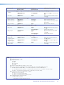
Commands and Responses.............................. 21
Using the Command and Response Tables... 21
Symbol Definitions......................................... 22
SIS Command and Response Table.................. 26
Part Numbers and Accessories......................... 36
Included Parts............................................... 36
Optional Accessories..................................... 36
Rear Panel Connections...................................... 5
Rear Panel Cabling.............................................. 5
Operation................................................................. 7
Front Panel Overview........................................... 7
The DSC 301 HD OSD Menu System —
Configuration and Adjustments........................... 8
OSD Menu Navigation Using Front Panel
Controls.......................................................... 8
Menu Overview................................................ 8
Resolutions and Refresh Rates...................... 18
Custom EDID or Custom Output Resolution.. 19
Power Save .................................................. 19
Output Rate Reset ........................................ 19
Front Panel Lockout (Executive Modes)............. 19
Warranty....................................................................
Contact Information................................................
DSC 301 HD • Contents
v
DSC 301 HD • Contents
vi
Introduction
This guide contains information about the Extron DSC 301 HD Digital Scaling Converter
with instructions for experienced installers on how to install, configure, and operate the
equipment.
In this guide the terms “digital scaler” and “scaler” are used interchangeably and refer to
the DSC 301 HD model.
This section gives a basic description and the key features of the DSC 301 HD scaler.
DSC 301 HD Description
The DSC 301 HD is a 1-inch high, half rack wide, three input, HDCP-compliant video
scaler that includes an HDMI input, configurable high resolution analog and composite
video inputs, and a single HDMI output.
The DSC 301 HD accepts a wide variety of video formats including HDMI, HDTV, RGB,
component, and standard definition video. It features advanced Extron video signal
processing with 1080i deinterlacing, EDID Minder, Key Minder, and automatic input
switching. Audio from any of three stereo inputs may be embedded onto the HDMI
output. Front panel controls, an intuitive on-screen display, plus USB and RS-232
connections provide flexible control and monitoring.
The unit can be rack mounted or installed under a desk using the optional MBU 125 rack
mounting brackets.
The DSC 301 HD features advanced video processing with the ability to scale HDMI,
HDTV, RGB, and standard definition video signals to a common high resolution output.
It accepts and outputs signals up to 1920x1200, including HDTV 1080p/60 and
2048x1080. The DSC 301 HD also features Deep Color processing and high performance
deinterlacing of 1080i to deliver optimal image quality through advanced motion
compensation. In addition, the color space and chroma subsampling of the HDMI output
can be automatically set to ensure compatibility with a connected DVI or HDMI display.
Output scan rates are available from VGA (640x480) to 1920x1200 resolution, as well as
HDTV at 720p, 1080i, 1080p/60 Hz, and 2k/60Hz.
NOTE:
list.
See the Resolution and Refresh Rate table on page 18 for a complete
The DSC 301 HD features automatic 3:2 and 2:2 pulldown detection, which maximizes
the image detail and sharpness for content sources originating from film. The scaler also
uses a digital 3D adaptive comb filter that optimizes decoding of NTSC, PAL, and SECAM
sources for integration into systems worldwide.
DSC 301 HD • Introduction
1
Key Features
Inputs
•
Video — The DSC 301 HD has the following connectors: one HDMI connector,
one 15-pin HD connector for RGBHV or HD/SD component video, and one BNC
connector for composite video.
•
Auto-Image setup — When activated, the unit automatically detects the resolution
of the incoming video signal and sets the total pixels, phase, active pixels, and active
lines, as well as the horizontal and vertical starting points.
•
Auto Input memory — When activated, the unit automatically saves input sampling
and picture settings based on the incoming signal. When the same signal is detected
again, these image settings are automatically recalled from memory.
•
Auto-switching between inputs — Auto-switching allows for simple, unmanaged
installation in locations such as in a lectern or under a conference table. When
multiple inputs are active, the switching priority is configurable.
•
HDMI, RGB, HDTV, and video scaling to HDMI — Digital and analog video sources
can all be scaled to high resolution HDMI output.
•
Clean switching — Clean cut through black and fade through black transition
effects are available to enhance presentations by eliminating distractions during input
switching.
•
Audio — The DSC 301 HD has the following connectors: three 3.5 mm stereo mini
jacks for analog audio input, and an embedded HDMI digital audio input.
•
HDMI audio embedding — Analog input audio signals can be embedded onto the
HDMI output signal.
•
Audio input gain and attenuation — Gain or attenuation can be adjusted for each
analog audio input to eliminate noticeable differences when switching between
sources.
•
Audio input assignment — Each video input can be assigned to any analog audio
input. This enables all three video inputs to share a single analog audio input. The
HDMI input can be set to pass incoming digital audio, embed the analog audio, or to
automatically embed the analog audio when no digital audio is detected.
•
Video and Audio — The DSC 301 HD has one HDMI output.
•
Selectable output — Available output rates include computer-video 640x480 up to
1920x1200, HDTV rates up to 1080p/60, and 2048x1080.
•
Output Standby Mode — Can be set to automatically mute video and sync
output to the display device when no active input signal is detected. This allows
the projector or flat-panel display to automatically enter into standby mode to save
energy and enhance lamp or panel life.
•
Aspect ratio control — The aspect ratio of the video output can be controlled by
selecting a FILL mode, which provides a full screen output, or a FOLLOW mode,
which preserves the original aspect ratio of the input signal.
•
HDCP authentication and signal presence confirmation — Provides real-time
verification of HDCP status for each digital video input and output. This allows for
simple, quick, and easy signal and HDCP verification through front panel LEDs or
RS-232, providing valuable feedback to a system operator or helpdesk support staff.
Outputs
DSC 301 HD • Introduction
2
•
HDCP Visual Confirmation — This provides a full screen green output signal when
HDCP-encrypted content is transmitted to a non-HDCP compliant display, providing
immediate visual confirmation that protected content cannot be viewed on the
display.
•
HDMI to DVI Interface Format Correction — Automatically enables or disables
embedded audio and infoframes, and sets the correct color space for proper
connection to HDMI and DVI displays.
•
AFL (Accu-RATE Frame Lock) — A patented technology exclusive to Extron that
locks the output frame rate to a designated input to eliminate stuttering caused by
frame rate conversion.
•
Audio switching transitions — The audio output level automatically ramps down
and then ramps up during switching transitions.
•
Integrated audio delay — The audio output is automatically delayed to compensate
for latency introduced by the video processing.
•
Advanced scaling engine with 30-bit processing and 1080i deinterlacing —
Image scaling and video format conversion are performed at 30-bit precision for
enhanced color accuracy and picture detail. High performance deinterlacing for 1080i
signals from HD sources delivers optimized image quality.
•
HDCP compliant — Fully supports HDCP-encrypted sources, with selectable
authorization for unencrypted content.
•
Supported HDMI — This features include data rates up to 6.75 Gbps, Deep Color,
and HD lossless audio formats
•
Key Minder — Key Minder authenticates and maintains continuous HDCP
encryption between input and output devices to ensure quick and reliable switching in
professional AV environments.
•
EDID Minder — EDID Minder automatically manages EDID communication and
ensures that all sources power up properly and reliably output content for display.
•
Image freeze control — A live image can be frozen using RS-232 serial control.
•
On-screen display — Displays status information pertaining to the currently selected
input, including resolution, format, and HDCP status, and facilitates easy system
setup and troubleshooting.
•
Power Save Mode — Can be placed in a low power standby state to conserve
energy when not in use.
•
Picture control adjustment — Used for brightness, contrast, color, tint, and detail
settings, as well as horizontal and vertical positioning, and sizing.
•
Automatic 3:2 and 2:2 pulldown detection — Advanced film mode processing
techniques that help maximize image detail and sharpness for NTSC, PAL, and HDTV
1080i sources that originated from film.
•
Quad standard, 3D composite video decoding — A temporal, 3D adaptive comb
filter provides advanced decoding of composite NTSC 3.58, NTSC 4.43, PAL, and
SECAM for integration into systems worldwide.
•
User presets — Memory presets are available for each input to store and recall
optimized image settings.
•
Internal test patterns for calibration and setup — The DSC 301 HD offers a crop
pattern, crosshatch, grayscale, color bars, alternating pixels, blue mode, and audio
pink noise.
General
DSC 301 HD • Introduction
3
•
Front panel security lockout — This feature can block all front panel control, or limit
front panel to input selection only. All functions however, are available through RS-232
control.
•
RS-232 control port — Enables the use of serial commands for complete control
and configuration or integrated into a control system. Extron products use the SIS™ Simple Instruction Set command protocol, a set of basic ASCII code commands that
allow for quick and easy programming.
•
Front-panel USB configuration port — Enables easy configuration without having
to access the rear panel.
•
1 inch (2.5 cm) high, half rack width metal enclosure
•
Includes LockIt HDMI cable lacing brackets
•
Energy-efficient external universal power supply included, replacement
PS-1210C part number 70-775-01 — Provides worldwide power compatibility, low
power consumption, and reduced operating costs.
DSC 301 HD • Introduction
4
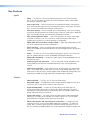
Rear Panel
Connections
This section describes how to connect cables to a DSC 301 HD scaler.
Rear Panel Cabling
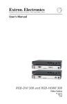
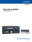
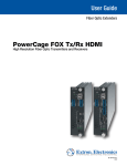
The illustration below shows the rear panel features of the DSC 301 HD.
DSC 301 HD
POWER
POWER
12V
12V
1.0A
1.0AMAX
MAX
22
11
1
DSC
DSC301
301HD
HD
INPUTS
INPUTS
33
11
22
VIDEO
VIDEO
RGB/R-Y,Y,B-Y
RGB/R-Y,Y,B-Y
HDMI
HDMI
AUDIO
AUDIO
2
3
4
5
Figure 1.
REMOTE
REMOTE
RS-232
RS-232
33
OUTPUT
OUTPUT
Tx
Tx Rx
RxGG
6
7
DSC 301 HD Rear Panel Features
a Power input — Insert the cord from the supplied 12 V, 1.0 A power source into
this 2-pole connector. The front panel control and input selection buttons light in
sequence during power-up.
b Input 1 — Connect a suitable composite video input to this BNC connector.
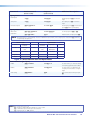
c Input 2 — Connect a suitable input to this configurable analog 15-pin HD (VGA)
connector for RGBHV, HD component video, or YUVi signals.
The analog input port can be configured to accept RGB (RGBHV, RGBs) or
component video (bi- or tri-level) signals. The default setting is for RGB. The table
below shows the pinouts for each format type on the 15-pin HD (VGA) connector. The
15-pin HD supports EDID emulation.
Pinout Table for 15-pin HD Connector
Pin
RGBHV
RGBs
Component
1
Red
Red
R-Y
2
Green
Green
Y
3
Blue
Blue
B-Y
4
No Connection
No Connection
5
No Connection
No Connection
6
Red Return
Red Return
R-Y Return
7
Green Return
Green Return
Y Return
8
Blue Return
Blue Return
B-Y Return
9
10
Ground
Ground
11
No Connection
No Connection
12
EDID/DDC
EDID/DDC
13
H Sync
C Sync
14
V Sync
15
EDID/DDC
EDID/DDC
5
1
15
11
DSC 301 HD • Rear Panel Connections
5
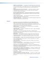
d Input 3 — Connect an HDMI source to this HDMI connector.
Audio from the HDMI input can be de-embeded from the HDMI source. This allows
the user to choose to select audio either from the HDMI input or the analog audio 3.5
mm TRS inputs. The default selection is 2-channel digital audio from the HDMI input.
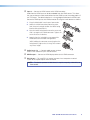
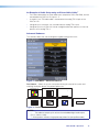
Secure the HDMI input to the HDMI connector c using the LockIt bracket as follows:
1. Plug the HDMI cable into the panel connection.
2. Loosen the HDMI connection mounting screw
from the panel enough to allow the LockIt lacing
bracket to be placed over it.
3. Place the LockIt lacing bracket onto the screw and
slide it up against the HDMI connector. Tighten the
screw to secure the bracket.
2
1
3
UT
TP
OU
4. Loosely place the included tie wrap around the
HDMI connector and LockIt lacing bracket.
While holding the connector securely against the
lacing bracket, tighten the tie wrap, then remove
any excess length.
3
4
e Audio inputs 1-3
— Connect audio sources to these
three 3.5 mm stereo mini jack TRS connectors.
f HDMI output — Connect an HDMI display device to this HDMI connector.
g RS-232 port — For serial RS-232 control, connect a host computer or control
system to the 3-pole captive screw connector.
NOTE: The default protocol is 9600 baud, 1 stop bit, no parity, 8 data bits, no
flow control.
DSC 301 HD• Rear Panel Connections
6
Operation
This section of the manual discusses the operation of a DSC 301 HD device, and is
divided into the following sections:
•
Front Panel Overview
•
The DSC 301 HD Menu System — Configuration and Adjustments
•
Front Panel Lockout (Executive Modes)
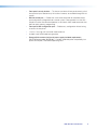
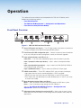
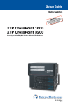
Front Panel Overview
1
4
11
22
33
HDCP
HDCP
ADJUST
ADJUST
INPUT
INPUT
CONFIG
CONFIG
OUTPUT
OUTPUT
Extron
Extron
MENU
MENU
3
2
ENTER
ENTER
5
DSC
DSC301
301HD
HD
6
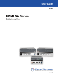
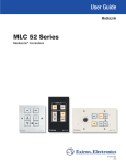
Figure 2. DSC 301 HD Front Panel Features
a Status LED (power and signal) — This LED lights amber when power is present but
no signal, and green when power and signal are both present.
b Front Panel mini USB configuration port — Connect a control system or computer
to this mini USB port for device configuration, control, and firmware upgrades.
c Input selection buttons and LEDs (1-3) —
Input LEDs — The LED of the selected input lights when the button is pressed.
Input 1 (composite video input button) — Input 1 selects the composite video
input.
Input 2 (configurable input button) — Input 2 selects the RGB (RGBHV, RGBS) or
YUV (YUV-HD, YUVp, YUVi) input.
Input 3 (HDMI/DVI button) — Input 3 selects the HDMI or DVI input signal.
d HDCP content LEDs — These LEDs indicate HDCP status for inputs and output;
• Light green when the input or connected display is HDCP encrypted.
• Remain unlit when the current input or HDMI output is not HDCP encrypted.
• Flash amber when the video output has been disabled (such as when in sync mute
or screen saver mode).
e Menu Navigation buttons (Menu and Enter) —
Menu — Press this button to access and move through the OSD menu system.
Enter — Press this button to step through the OSD submenus.
See the “The DSC 301 HD OSD Menu System — Configuration and
Adjustments” section on the next page.
g Adjustment knobs (horizontal [and vertical {) — When using the menu system,
rotate either of these two knobs to scroll through the menu options and to make any
adjustments.
DSC 301 HD • Operation
7
The DSC 301 HD OSD Menu System — Configuration and Adjustments
Scaler configuration and adjustments can be performed by using the On-screen Display
(OSD) menu or the Extron Simple Instruction Set (SIS) of commands (see the “SIS
Communication and Control” section).
The OSD menu can be seen on the connected display device.
OSD Menu Navigation Using Front Panel Controls
Menu button — Press the Menu button to activate or deactivate the main menu.
Enter button — Press the Enter button to move between the submenus of a selected
main menu item and to exit and accept the setting.
Adjust ({, [) knobs — In the menu configuration mode, rotate the Adjust horizontal
([) knob and Adjust vertical ({) knob to scroll through submenu options and to make
adjustment selections.
Menu Overview
The OSD menu has nine configuration submenus; two of which are read only information
menus. The table below shows the submenus and submenu items.
OSD Menu
Submenu
Submenu Item
Quick Setup
Auto-Image
Input x
Format
Input 2
EDID
Input 3
EDID
Output
Resolution
Audio Mute
Test
Pattern
User Presets
Recall
Save
Clear
Picture Controls
Image Position
(H and V)
Image Size
(H and V)
Brightness
Contrast
Color
Tint
Detail
Input
Auto-Image
Input x
Input
Format
Input x
Film Mode
Pixel Start
(H and V)
Active
Pixels
(H and V)
Total Pixels
Phase
Input x
HDCP
Authorized
Input x
EDID
Output
Resolution
HDMI
Format
HDCP
Notification
Input AFL
Audio
Audio Mute
Input x
Audio
Format
Input x
Gain/
Attenuation
Advanced
Test Pattern
Screen
Saver
Screen Saver
Timeout
Input x
AutoImage
Input x
Aspect
Ratio
Input x
AutoMemory
Overscan
Auto Switch
Factory
Reset
Communication
Remote Port
Device Info
Temperature
Active Input
Details
Output
Details
AFL Status
HDCP
Status
Display
Information
Firmware
Build
Details
(read only menu)
NOTE:
“Input x” refers to the selected input; for example “Input 2”.
NOTE: The Device Info menu and the Communication menu are read-only and
gives current device status.
Using each of the submenus, the video and audio inputs and the HDMI output of the
DSC 301 HD can be configured. In addition, the user can save and recall the input
configuration as an User Preset. The Advanced submenu allows the user to choose a test
pattern to aid in the system setup, as well as set up a screen saver display when there
are no active input signals. The remote control port configuration can be viewed using the
read-only Communication submenu. Elements of the device status can be viewed using
the read-only Device Info submenu. See each submenu on the following pages for details.
DSC 301 HD • Operation
8
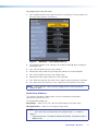
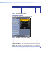
To navigate and use the OSD menu:
1. Press the Menu button once to open the menu on the display, The menu opens with
the Quick Setup submenu (see figure 3).
Figure 3.
OSD Menu — Quick Setup Submenu
2. If the desired submenu is not showing, use the Adjust knobs ({, [) to navigate to
the desired menu.
3. Press the Enter button to access the submenu.
4. Rotate either Adjust knob to cycle through the submenu to the desired option.
5. Press the Enter button to access the submenu item.
6. Rotate either Adjust knob to adjust the value as desired.
7. Press Enter to accept the new value. Press it again if action confirmation is required.
8. Press Menu to exit the sub menu. Press it again to exit and close the main menu.
NOTE: In any submenu, values that do not apply to the current input will be
shown as “N/A”.
Quick Setup Submenu
This submenu (see figure 3 above) allows the user to make basic configuration
adjustments to the DSC 301 HD.
The configurable variables are:
Auto-Image — Select this to start a one-time Auto-Image on the current input.
INx: Input Format — Select this to change the input format.
NOTES:
•
“INx” refers to the selected input; for example “Input 2”, as shown in
figure 4.
• View only for inputs 1 (composite video) and 3 (HDMI), selectable for input 2
(RGB or YUV).
DSC 301 HD • Operation
9
IN2: EDID — Select this to match the output rate or to set a discrete EDID (see the table
on page 18 for EDID data).
IN3: EDID — Select this to match the output rate or to set a discrete EDID (see the table
on page 18 for EDID data).
Output Resolution — Select this to set the resolution and refresh rate for the output.
There are 83 factory installed output resolutions and rates, and 3 custom user defined
blocks. See the table on page 18 for details.
Audio Mute — Select this to turn the audio mute option on or off.
Test Pattern — Select this to choose a suitable test pattern when setting up the
DCS 301 HD and the corresponding output display. Available patterns are: Off (no test
pattern), Crop, Alternating pixels, Color bars, Gray scale, Blue Mode, and Audio test (pink
noise).
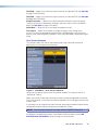
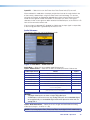
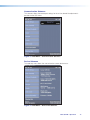
User Preset Submenu
This submenu allows the user to save centering and sizing information and picture
adjustments as a User preset for future recall.
Figure 4. OSD Menu — User Presets Submenu
Up to three user presets per input can be saved or recalled. The submenu also has a
“clear preset” setting.
Select save, recall, or clear and use the adjust knobs to select the applicable user preset.
Press Enter to recall, save or clear the preset as required. Press Enter again to confirm the
chosen action.
A user preset can be saved on one input resolution (for example saved on 480p) and later
recalled onto another resolution (for example, recalled onto 1080p).
NOTE:
If an unsaved user preset is recalled, INVALID PRESET is displayed.
An additional 128 global Input presets are available via SIS commands (see the SIS
Communication and Controls section on page 20, for commands).
DSC 301 HD • Operation
10
A summary and comparison of the User and Input Presets stored values is shown below.
User Presets
Input Presets
Color
H Image Size
Input Type
Color
H Start
H Image Size
Tint
V Image Size
Preset Name
Tint
V Start
V Image Size
Contrast
H Image Position
Audio Gain/Attenuation
Contrast
H Active
H Image Position
Brightness
V Image Position
Film Mode
Brightness
V Active
V Image Position
Detail
Preset Name
Detail
Phase
Total Pixels
Figure 5. User and Input Preset Values
Picture Controls Submenu
This submenu allows the user to adjust all of the picture settings.
Figure 6. OSD Menu — Picture Controls Submenu
Image Position — Select this to adjust the horizontal and vertical position of the image
(range depends on the current output rate).
Image Size — Select this to adjust the horizontal and vertical size of the image. The
range is limited by the output resolution (maximum size is 2x the output resolution).
Brightness and Contrast — Select this to independently adjust brightness and contrast
(range is 0 to 127, default is 64).
Color and Tint — Select this to adjust the color and tint (range is 0 to 127, default is 64).
NOTE:
Color and Tint only apply to NTSC inputs.
Detail — Select this to adjust the detail (range is 0 to 127, default is 64).
DSC 301 HD • Operation
11
Input Submenu
This submenu allows the user to configure the active input.
Figure 7. OSD Menu — Input Submenu
Auto-Image — Select this to start a one-time Auto-Image on the active input.
Input x: Input Format — Select this to change the active input format.
NOTE: Only input 2 can be changed (RGB or YUV). Input 1 is always composite
video and input 3 is always HDMI.
Input x: Film Mode — Select this to turn Film Mode on (auto detect mode) or off.
(Pixel) Start — Select this to adjust the horizontal and vertical pixel start (range is 0 to
+255, default is 128).
Active (pixels) — Select this to adjust the horizontal and vertical active pixels (range is
dependant on input).
Total Pixels and Phase — Select this to set the number of active pixels and the phase
value.
Input x: HDCP Authorized — Select this to turn the HDCP Authorized on (default) or off.
NOTE:
Applicable to HDMI input 3 only.
When disabled (off) the DSC 301 HD will not display content that requires HDCP, and
displays ether a blank screen or a warning message from the input source.
Input x: EDID — Select this to change the EDID (resolution and refresh rate) for the active
input. Set to either match output rate, or a custom user-defined EDID, or a factory setting
(see table on page 18 for EDID data).
DSC 301 HD • Operation
12
Output Submenu
This submenu allows the user to configure the output.
Figure 8. OSD Menu — Output Submenu
Resolution — Select this to change the resolution and refresh rate for the connected
output display (see the table on page 18 for details).
HDMI Format — Select this to set the HDMI output format. Choices are :
•
•
•
•
•
•
•
•
Auto — (based on sink EDID), default
DVI RGB 444
HDMI RGB 444 Full
HDMI RGB 444 Limited
HDMI YUV 444 Full
HDMI YUV 444 Limited
HDMI YUV 422 Full
HDMI YUV 422 Limited
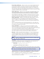
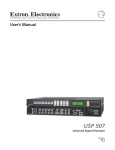
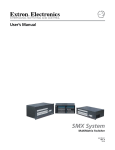
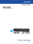
HDCP Notification — Select this to turn HDCP Notification on (default) or off.
The HDCP Notification provides a means of determining if HDCP content restrictions
are preventing a video signal from passing. The DSC 301 HD has the ability to notify the
user that they are currently trying to view HDCP protected content through a non-HDCP
compliant HDMI or DVI display. The options presented to the user during this scenario are
the ability to show a green screen with a moving “OSD bug” reading “HDCP CONTENT,”
or to disable this message, and instead output muted (black) video on non-HDCP
compliant displays.
Figure 9. Green HDCP Notification Screen
DSC 301 HD • Operation
13
Input AFL — Select this to turn the Extron Accu-Rate Frame Lock (AFL) on or off.
When enabled, this mode locks the output vertical refresh rate to the vertical refresh rate
of the currently selected input using Accu-Rate Frame Lock technology. This ensures
no frames of the input are repeated or dropped due to frame rate conversion. Input AFL
mode will cause glitches and/or interruptions in the output sync when a new input is
selected, or when a new signal has been routed to the selected input, as the DSC 301 HD
locks to the new vertical refresh rate.
If no input signal is detected (AFL disabled), or if locking to the input signal is not possible,
a free running pixel clock is generated by the DSC 301 HD.
Audio Submenu
This submenu allows the user to configure the audio.
Figure 10.OSD Menu — Audio Submenu
Audio Mute — Select this to turn global Audio Mute on or off
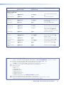
Input x: Audio Format — Select this to select the audio input format. Choices are:
Audio Input format
Details
Inputs
None
Mutes all audio for selected input
All
Analog TRS 1
Sets selected input to analog TRS 1 (default for input 1)
All
Analog TRS 2
Sets selected input to analog TRS 2 (default for input 2)
All
Analog TRS 3
Sets selected input to analog TRS 3
All
LPCM-2Ch Digital
Sets selected input to 2Ch digital audio (default for input 3)
Input 3 only
Multi-Ch Digital
Sets selected input to Multi-Ch digital audio
Input 3 only
LPCM-2Ch Auto (TRS 3)
Sets selected input to use 2Ch digital audio (when present),
else use analog TRS 3
Input 3 only
Multi-Ch Auto (TRS 3)
Sets selected input to use Multi-Ch digital audio
(when present), else use analog TRS 3
Input 3 only
NOTES:
• Multiple video inputs can share a single TRS audio input.
• HDMI Input 3 can be set to use any analog TRS input, or to embedded digital,
or to automatically use embedded digital audio when present or when not use
analog TRS 3.
Input x: Gain/Attenuation — Select this to set the gain and attenuation for analog
audio inputs (range is -18 dB to +12 dB).
NOTE: For analog inputs TRS1, TRS2, and TRS3, or for digital “Auto” modes only
DSC 301 HD • Operation
14
An Example of Audio Setup using an Extron Cable Cubby®
•
The Extron cable cubby has three video inputs (composite, RGB, and HDMI), and are
connected to the DCS 301 HD, inputs 1-3.
•
A single 3.5 mm TRS audio cable is connected to the analog TRS 3 input on the
DSC 301 HD.
•
Configure input 1 and input 2 to use audio from the analog TRS 3 input.
•
Configure input 3 to LPCM-2Ch Auto to use digital audio when present, or when not
present, to use analog TRS 3.
Advanced Submenu
This submenu allows the user to configure the global settings for the unit.
Figure 11.OSD Menu — Advanced Submenu
Test Pattern — Select this to use a test pattern during the setup of the system and
checking the display device. Test pattern options are:
COLOR BARS (8)
CROP
CROSSH ATCH
ALT PIXELS
GRAYSCALE
BLUE MODE
AUDIO TEST
Figure 12.Test Pattern Options
NOTES:
•
The audio test outputs pink noise on the embedded digital audio output
(Ch 1/2, 48kHz, 16 bit).
• All test patterns include a single pixel crop pattern line (except Blue mode).
DSC 301 HD • Operation
15
Screen Saver and Timeout — Select the screen saver to mute the video output when
no active video is detected. The screen saver can be set to a black (default) or a blue
background for a specific (time-out) duration, before the output sync is disabled. The
time-out duration can be set to Never (default), or to any duration from 1-500 seconds.
The screen saver option allows connected display devices to go into a low power standby
mode when the DSC 301 HD has no active input.
Input x: Auto-Image — Select this to turn the per-input Auto-Imaging mode on or off.
Auto-Image automatically attempts to size and position the image to Fill (or Follow the
native aspect ratio of the input) the screen every time a new input signal is detected.
When enabled, Auto Image mode is activated by switching physical inputs on the DSC
(e.g. IN2 to IN3), or by any interruption in input sync, even if the same input resolution is
detected (e.g. disconnecting and reconnecting the same input), or by a power cycle.
Input x: Aspect Ratio — Select this to set the per-input Aspect Ratio to FILL (fills the
entire output raster) or to FOLLOW (follows the native aspect ratio of the input).
When in Fill mode, if an Aspect Ratio adjustment for a single input rate is desired, the
correct size and center can be manually set up under Picture Controls (Image Size and
Position).
When in the Follow mode, each input rate will be displayed with its native aspect ratio
(4:3, 5:4, 15:9, 16:9, 16:10) with the correct letter box or pillar box settings visible under
the Image Size and Center Picture Controls.
Input x: Auto Memory — Select this to turn the per-input Auto Memory on or off.
The DSC 301 HD has 32 Auto Memory locations per input, for RGB/YUV and HDMI
inputs. YUV and RGB signals on the same input have unique Auto Memories; for example
720p YUV and 720p RGB are stored with unique Auto Memory settings.
Auto memory locations store the same Input Config and Picture Control values as an
Input Preset, except for Input Type, Preset Name, Film Mode, or Audio Gain/Att.
Overscan — Select this to set the overscan mode (0%, 2.5% or 5.0%) per input type.
This zooms and crops SMPTE inputs to mask edge effects and ancillary data that are
common in broadcast signals. Issuing an Auto‑Image with overscan enabled, runs an
Auto Phase routine (YUV and RGB only) and centers and sizes the input according to
table values.
NOTE: Overscan is valid only on SMPTE input rates (NTSC, PAL, SECAM, 480p,
576p, 720p, 1080i, or 1080p, or 2k).
Auto Switch — Select this to turn the Auto Switch mode on or off, and to set the priority.
The Auto Switch setting allows for basic, unmanaged, input switching based on the
presence of active input signals. Auto Switch mode options are:
• disabled (off)
•
setting priority to “high to low” (input 3 to input 1)
•
setting priority to “low to high” (input 1 to input 3).
Factory Reset — This resets the device back to factory defaults (retains current firmware).
NOTE: “FACTORY RESET” is displayed on the OSD for 1 minute after the reset to
allow time for the display device to sync with the DSC 301 HD output.
To reset the DSC 301 HD to factory setting, including original shipped firmware, press and
hold the Enter button for 20 seconds while applying power. The message “FIRMWARE
RESET” is displayed on the OSD to indicate the reset is completed.
When a FIRMWARE RESET is applied, the loaded current firmware is deleted and only the
factory firmware remains on the device.
DSC 301 HD • Operation
16
Communication Submenu
This submenu allows the remote port settings for the unit to viewed. No adjustment is
possible via the OSD menu.
Figure 13.OSD Menu — Communication Submenu
Device Submenu
This read-only menu allows the user to view the current device status.
Figure 14.OSD Menu — Device Info Submenu
DSC 301 HD • Operation
17
The viewable device status information is:
• device internal temperature (in degrees F and C)
• the current active input details (resolution, signal format, and total lines)
• output resolution and refresh rate and output format
• AFL status (locked or disabled)
• HDCP status (input status and HDMI output status)
• Display Info (resolution and refresh rate)
• Firmware build details
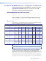
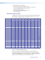
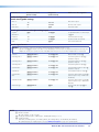
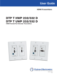
Resolutions and Refresh Rates
In addition to the 83 factory rates, there are also three custom, user-defined or captured
rates available (C1 - C3). When no rate is captured or uploaded to any of the custom
slots, they revert to the default setting — 720p/60 Hz.
Resolution
23.98 Hz
24 Hz
25 Hz
Custom 1 through 3
29.97 Hz
30 Hz
50 Hz
59.94 Hz
60 Hz
75 Hz
For captured or uploaded EDID tables
640 x 480
X
X
X
800 x 600
X
X
X
852 x 480
X
X
X
1024 x 768
X
X
X
1024 x 852
X
X
X
1024 x 1024
X
X
X
1280 x 768
X
X
X
1280 x 800
X
X
X
1280 x 1024
X
X
X
1360 x 765
X
X
X
1360 x 768
X
X
X
1365 x 768
X
X
X
1366 x 768
X
X
X
1365 x 1024
X
X
X
X
1440 x 900
X
X
1400 x 1050
X
X
1600 x 900
X
X
1680 x 1050
X
X
1600 x 1200
X
X
1920 x 1200
X
480p
576p
X
X
X
X
X*
X
720p
X
X
X
X
X
X
X
1080p
1080i
X
X
X
X
X
X
X
X
2048 x 1080
X
X
X
X
X
X
X
X
* = default value
Figure 15.Resolution and Refresh Rates
When a new custom rate is captured or uploaded, the On-screen Display (OSD)
dynamically updates with the new rate for that custom slot. For example, if a custom
480p EDID is uploaded to slot C1, the LCD would read “C1: 720x480”. These three
custom slots are shared between custom output resolutions (based on preferred timings 1
block) and custom EDID tables, which can be assigned to any input.
DSC 301 HD • Operation
18
Custom EDID or Custom Output Resolution
The user has the ability to capture EDID or upload EDID files to make custom EDID
available for emulation on inputs, or for the generation of custom output resolutions. The
user can import a 128 or 256 byte EDID “.bin” file from a PC or can capture the EDID from
an attached sink (display) device. This EDID can then be saved and stored in one of three
custom EDID slots, which are then available for custom EDID emulation or custom output
rate generation (custom rate based on the EDIDs preferred timings). These functions are
available via SIS (see the table on page 18).
Power Save
The DSC 301 HD has a power save mode that allows the user the ability to put the unit
into a low power state, via SIS command (see “Power Save Mode” on page 31). This
state effectively cuts the power consumption of the DSC in half. While in this mode, no
audio or video input processing takes place, the HDMI output and all front panel LEDs are
disabled.
The user has the ability to exit Power Save mode via any front panel button press, or by
disabling Power Save via SIS command.
The Power Save state is entered instantly after the associated command has been
received, but 5-10 seconds are required to resume from the Power Save state.
Output Rate Reset
If an output image cannot be displayed due to an incompatible output rate, the
DSC 301 HD can be reset via the front panel to either 1024x768 @60 Hz or 720p @60Hz.
To set the rate or toggle between 1024x768 @60 Hz and 720p @60Hz :
Press and hold inputs 1 and 3 simultaneously for approximately 3 seconds. The output
rate becomes 1024x768 @60 Hz. Again, press and hold inputs 1 and 3 simultaneously for
another 3 seconds and the output rate becomes 720p @60 Hz.
NOTE: The output rate will subsequently toggle between 1024x768 @60 Hz and
720p @60Hz each time inputs 1 and 3 are simultaneously pressed and held
down for 3 seconds.
Front Panel Lockout (Executive Modes)
The DSC 301 HD has three modes of front panel security lock that limit the operation of
the unit from the front panel.
Executive mode 0 (disabled) — The front panel is fully unlocked. This is the default
setting.
Executive mode 1 (enabled) — The front panel is completely locked. This mode can
only be enabled and disabled using SIS commands.
NOTE: When Executive mode 1 is implemented and a front panel button is
pressed, an OSD message indicates that Executive Mode 1 is enabled.
Executive mode 2 (enabled) — The front panel is locked except for input switching. This
mode can be enabled and disabled using front panel buttons or SIS commands.
To prevent accidental changes to settings, press the Menu and Next buttons
simultaneously for 2 seconds to enable front panel lockout mode (Executive Mode 2). An
OSD message is displayed indicating Executive Mode 2 is enabled.
To unlock it via the front panel, press the Menu and Next buttons simultaneously for 2
seconds. An OSD message is displayed indicating Executive Mode 2 is disabled.
DSC 301 HD • Operation
19
SIS Communication
and Control
The DSC 301 HD can be configured and controlled via a host computer or other device
(such as a control system) attached to the rear panel RS-232 connector or the front panel
USB port. Control is made using the Extron Simple Instruction Set (SIS) of commands.
Commands can be entered using a Telnet application such as the Extron DataViewer,
available at www.extron.com. See the DataViewer Help file for use.
This section describes SIS communication and control. Topics that are covered include:
•
Host to Scaler Communications
•
Commands and Responses
The scaler uses a protocol of 9600 baud, 1 stop bit, no parity, and no flow
control and the rear panel remote port RS-232 captive screw connector has
the pin assignments as shown at right.
REMOTE
RS-232
Tx Rx G
Host-to-Scaler Communications
SIS commands consist of one or more characters per field. No special characters are
required to begin or end a command sequence. When the DSC 301 HD determines that a
command is valid, it executes the command and sends a response to the host device.
All responses from the scaler to the host end with a carriage return and a line feed
(CR/LF = ]), indicating the end of the response character string (one or more
characters).
Scaler-initiated Messages
When a local event such as a front panel selection or adjustment takes place, the
DSC 301 HD scaler responds by sending a message to the host. No response is required
from the host. Example scaler-initiated messages are listed here.
•
In X! All
] (where X! is the input number during an input switch).
•
Reconfig
] The DSC 301 HD sends this response when a new signal is detected.
•
X@ ] The DSC 301 HD sends this response when a hot plug event on
output X@ is detected.
HplgO
Copyright Information
] © Copyright 2013, Extron Electronics, DSC 301 HD, Vx.xx, 60-1253-01]
The copyright message is displayed upon connecting to the product via USB or RS-232.
Vx.xx is the firmware version number.
DSC 301 HD • SIS Communication and Control
20
Error Responses
When the DSC 301 HD receives a valid command, it executes the command and sends
a response to the host device. If the unit is unable to execute the command because the
command contains invalid parameters, it returns an error response to the host.
Error Numbers
E01 — Invalid input number
E10 — Invalid command
E11 — Invalid preset number
E13 — Invalid parameter
E14 — Not valid for this configuration
E17 — Invalid command for signal type
E22 — Busy
E25 — Device not present
Error Response References
= Commands that give an E14 (invalid command for this configuration) error if sent to a
product whose current configuration does not support the command
14
Commands and Responses
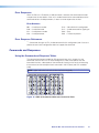
Using the Command and Response Tables
The command and response table for SIS commands later in this chapter lists the
commands that the DSC 301 HD scaler recognizes as valid, the responses that are
returned to the host, a description of the command’s function or the results of executing
the command, and an example of each command in ASCII (Telnet) and URL encoded
(web).
NOTE: Upper and lower case text can be used interchangeably.
ASCII to HEX Conversion Table
Space
•
Figure 16.ASCII to Hexadecimal Character Conversion Table
DSC 301 HD • SIS Communication and Control
21
Symbol Definitions
• = Space
] = Carriage return with line feed
¦ or} = Carriage return with no line feed
E or W = Escape
14
= Superscripts indicate the error message displayed if the command is entered incorrectly or
with invalid parameters. See “Error Response References” on page 21.
X! = Input selection, 1-3
X@ = Output selection, 1 = HDMI
X# = Input video format:
1 = RGB
2 = YUV
3 = Composite
4 = HDMI
X$ = Horizontal or vertical start — 0 to 255 (default midpoint = 128)
X% = Pixel phase — 0 to 63 (default = 31)
X^ = Total pixels — (±512 of the default value)
X& = Active pixels — (±512 of the default value)
X* = Active lines — (±256 of the default value)
X( = Enable or disable; 0 = Off or disable, 1 = On or enable
X1) = Input standard:
0 = No signal detected
3 = NTSC 4.43
1 = NTSC 3.85
4 = SECAM
2 = PAL
- = N/A (occurs when input is an active RBG, YUV [but not NTSC/PAL], or HDMI signal
X1! = Internal temperature (in degrees Celsius)
X1@ = Horizontal and vertical frequencies (format is three-digit with single decimal and leading zeros
for example, 075.3)
X1# = Text label or preset name: up to 16 characters
NOTE: User and input presets saved without a name are saved with the default names
“User Preset xx” (for example, User Preset 12) or Input Preset xxx (for example
Input Preset 006).
X1$ = Picture adjustment — 0 to 127 (default 64)
X1% = Horizontal and vertical position, range depends on resolution, with leading “+” or “-”,
for example, “-1075”
X1^ = Horizontal and vertical size, range range depends on resolution
DSC 301 HD • SIS Communication and Control
22
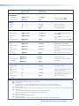
X1& = Scaler resolution or EDID emulation:
0 = Automatic: match current output resolution (default for EDID emulation) OSD reads
“Match Output”
1 = Output #1 (HDMI connector — available for Export EDID commands only)
2 = Custom EDID or output rate #1
3 = Custom EDID or output rate #2
4 = Custom EDID or output rate #3
SIS variables for EDID resolution and refresh rate combination (where X1& = 10 through 92)
Resolution
60 Hz
75 Hz
640x480
23.98 Hz
24 Hz
25 Hz
29.97 Hz
30 Hz
50 Hz
10
59.94 Hz
11
12
800x600
13
14
15
852x480
16
17
18
1024x768
19
20
21
1024x852
22
23
24
1024x1024
25
26
27
1280x768
28
29
30
1280x800
31
32
33
1280x1024
34
35
36
1360x765
37
38
39
1360x768
40
41
42
1365x768
43
44
45
1366x768
46
47
48
1365x1024
49
50
51
1440x900
52
53
54
1400x1050
55
56
1600x900
57
58
1680x1050
59
60
1600x1200
61
62
1920x1200
63
64
480p
576p
65
66
71
72
73*
74
75
76
67
720p
68
69
70
1080i
1080p
77
78
79
80
81
82
83
84
2048x1080 2k
85
86
87
88
89
90
91
92
* Default output resolution
Figure 17. SIS Command EDID Table
X1* = Test patterns:
0 = Off (default)
1 = Crop
2 = Alternating pixels
3 = Crosshatch
4 = Color bars
5 = Grayscale
6 = Blue mode
7 = Audio Test (crop pattern, OSD text “Audio Test”, pink noise; Ch 1/2, 48 kHz, 24 bit)
X1( = User presets — 1 to 3 (for each input)
X2) = Input presets — 1 to 128 (global for device)
DSC 301 HD • SIS Communication and Control
23
X2! = On-screen menu time-out or screen saver sync timeout, (default = 60 seconds)/output sync
time-out (default = 501 - never)
0 = OSD never displayed or output sync is instantly disabled with no active input
1 to 500 = 1 second increments
501 = OSD never times out, output sync is never times out
X2@ = Executive mode status:
0 = Off or disable, (default)
1 = Exec Mode 1 — Complete front panel lockout
2 = Exec Mode 2 — Partial front panel lockout (only input selection available)
X2# = Overscan (applied to SMPTE [NTSC, PAL, SECAM, 480p, 576p, 720p, 1080i, 1080p]
input rates):
0 = 0.0% (default for RGB, HDMI) — a “true” Auto-Image will be executed on SMPTE inputs.
1 = 2.5% (default for YUV, composite) — an Auto-Image command snaps to a 2.5% table;
no true Auto-Image.
2 = 5.0% an Auto-Image command snaps to a 5.0% table; no true Auto-Image.
X2$ = Aspect ratio:
1 = Fill: each input rate will automatically fill the entire output raster (default)
2 = Follow: each input rate will be displayed with its native aspect ratio
X2% = Screen saver mode:
1 = Black screen (default)
2 = Blue output
X2^ = Video mute;
0 = Off or disable
1 = On or enable (mute to black)
2 = mute all output sync and video
X2& = Auto-Image threshold value, 0 (black) though 100 (white), default = 25
X2* = HDCP status (valid only on TMDS inputs or outputs):
0 = No sink or source detected
1 = Sink or source detected with HDCP
2 = Sink or source detected but no HDCP is present
X2( = Video switching effect:
0 = Cut (audio ramps-down and ramps-up between inputs)
1 = Fade thought black (default) (audio ramps-down and ramps-up between inputs)
X3! = HDMI output format:
0 = Auto (default), based on sink EDID
1 = DVI
2 = HDMI RGB “Full”
3 = HDMI RGB “Limited”
4 = HDMI 444 YUV “Full”
5 = HDMI 444 YUV “Limited”
6 = HDMI 422 YUV “Full”
7 = HDMI 422 YUV “Limited”
X3@ = Auto switch mode:
0 = Disable (default)
1 = Gives priority to the highest input (3 then 2 then 1)
2 = Gives priority to the lowest input (1 then 2 then 3)
X3# = Audio gain and attenuation: -18 through + 12 dB, (with leading “+” or “–“)
DSC 301 HD • SIS Communication and Control
24
X3$ = Audio input type:
0 = None, input is muted
1 = Analog, (TRS 1)
2 = Analog, (TRS 2)
3 = Analog, (TRS 3)
4 = LPCM-2Ch, (embedded in HDMI input, LPCM-2Ch audio requested from source
via EDID)
5 = Multi-Ch, (embedded in HDMI input, all audio formats allowed via EDID)
6 = LCPM-2Ch Auto, (LCPM 2Ch audio requested from source via EDID).
Scaler uses embedded digital audio when present, or defaults to TRS input 3
7 = Multi-Ch Auto, (Multi-Ch audio is requested from source via EDID).
Scaler uses embedded digital audio when present, or defaults to TRS input 3
NOTE: Inputs 1 and 2 can only be set to X3$ = 0, 1, 2 or 3; attempting to set these inputs
to a digital format gives an “E14” error message.
X3% = Video signal status
0 = Video / TMDS signal not detected
1 = Video / TMDS signal detected
X3^ = Power Save mode
0 = Full power mode (Default)
1 = Low power state
X3& = Screen saver status
0 = Active input detected; timer not running
1 = No active input; timer is running; output sync still active
2 = No active input; timer has expired; output sync disabled
X3* = Input AFL
0 = Disabled; (default); free running pixel clock is generated internally
1 = Input lock enabled; locks output vertical to the selected input vertical refresh rate.
X3( = Input AFL status
0 = Input signal AFL disabled
1 = Input signal AFL enabled, but cannot lock to applied input signal. Device defaults to
set output rate/refresh
2 = Input signal AFL enabled, output locked to applied input signal
X4) = HDMI input HDCP authorization status:
0 = Block HDCP encryption
1 = Allow HDCP encryption (default for input 3)
The command and response tables for SIS commands start on the next page
DSC 301 HD • SIS Communication and Control
25
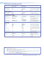
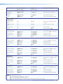
SIS Command and Response Table
Command
ASCII Command
(host to scaler)
Response
(scaler to host)
Additional Description
Input selection
Video and audio
X!!
InX!•All]
Select video and audio from input X!.
View current input
!
X!]
View current selected input X! (video
only).
Set video format
X!*X#\
TypX!*X#]
Set input X! to format X#.
View set format
X!\
X#]
View set video format of input X!.
Input video format
Input EDID (VGA and HDMI)
Assign EDID to
input
EAX!*X1&EDID}
EdidAX!*X1&]
Assign EDID resolution and refresh rate
X1& for input X!.
View assigned EDID
data
EAX!EDID}
X1&]
View assigned EDID resolution and
refresh rate X1& for input X!.
(Verbose mode response)
Save an output
EDID to custom slot
ESX@*X1&EDID}
EdidSX@*X1&]
Save output X@ EDID to X1&. (Valid for
X1& = 2, 3, 4 only and X@ = 1 only.)
Enable
X!*1A
ImgX!*1]
Activate Auto-Image for input X!.
Disable
X!*0A
ImgX!*0]
Turn Auto-Image off for input X!.
View
X!A
X(]
View Auto-Image setting X( for X!.
Execute
A
Img]
Execute an Auto-Image to the selected
input (follows current aspect setting).
Execute and Fill
1*A
Img1]
Execute an Auto-Image and fill entire
output.
Execute and Follow
2*A
Img2]
Execute an Auto-Image and follow the
aspect ratio of the input.
EdidAX!*X1&]
Auto-Image
Auto-Image threshold value (luminosity value which the scaler defines as active video for Auto-Image)
Set value
EX2&ALVL}
View
EALVL}
AlvlX2&]
X2&]
Set global Auto-Image luminosity
value X2&.
View global Auto-Image luminosity
value X2&.
NOTE: X! = Input number: 1 to 3
X@ = Output selection: 1 = HDMI
X# = Input video format: 1 = RGB, 2 = YUV, 3 = Composite, 4 = HDMI
X( = Enable/Disable: 0 = Off or disable, 1 = On or enable
X1& = Scaler resolution or EDID emulation, 0 = Automatic: match current output resolution (default), 2 = Custom EDID or output rate
#1, 3 = Custom EDID or output rate #2, 4 = Custom EDID or output rate #3.
For variables 10-92, see the SIS EDID table on page 23.
X2& = Auto-Image threshold value: 0 (black) though 100 (white), default = 25
DSC 301 HD • SIS Communication and Control
26
Command
ASCII Command
(host to scaler)
Response
(scaler to host)
Additional Description
Horizontal start
Specify a value
EX$HSRT}
HsrtX!*X$]
Set horizontal location of first active
pixel for current input.
Increment value
E+HSRT}
HsrtX!*X$]
Increment horizontal start position.
Decrement value
E-HSRT}
HsrtX!*X$]
Decrement horizontal start position.
View
EHSRT}
X$]
Show horizontal location of first active
pixel for current input.
Specify a value
EX$VSRT}
VsrtX!*X$]
Set vertical location of first active pixel
for current input.
Increment value
E+VSRT}
VsrtX!*X$]
Increase vertical start.
Decrement value
E-VSRT}
VsrtX!*X$]
Decrease vertical start.
View
EVSRT}
X$]
Show vertical location of first active
pixel for current input.
Vertical start
Pixel phase (available only for RGB and YUV input signals)
Specify a value
EX%PHAS}
PhasX!*X%]
Adjust the pixel phase to specified
value X% for current input.
Increment value
E+PHAS}
PhasX!*X%]
Increase the pixel phase.
Decrement value
E-PHAS}
PhasX!*X%]
Decrease the pixel phase.
View
EPHAS}
X%]
Show pixel phase for current input.
Total pixels (available only for RGB and YUV input signals)
Specify a value
EX^TPIX}
TpixX!*X^]
Adjust the total pixels to specified
value X^ for current input.
Increment value
E+TPIX}
TpixX!*X^]
Increase the total pixels.
Decrement value
E-TPIX}
TpixX!*X^]
Decrease the total pixels.
View
ETPIX}
X^]
Show the total pixels for current input.
Specify a value
EX&APIX}
ApixX!*X&]
Adjust the active pixels to a specified
value X& for current input.
Increment value
E+APIX}
ApixX!*X&]
Increase the active pixels.
Decrement value
E-APIX}
ApixX!*X&]
Decrease the active pixels.
View
EAPIX}
X&]
Show active pixels for current input.
Specify a value
EX*ALIN}
AlinX!*X*]
Adjust the active lines to a specified
value X* for current input.
Increment value
E+ALIN}
AlinX!*X*]
Increase the active lines.
Decrement value
E-ALIN}
AlinX!*X*]
Decrease the active lines.
View
EALIN}
X*]
Show the active lines for current input.
Active pixels
Active lines
NOTE: X!
X$
X%
X^
X&
X*
= Input selection: 1 to 3
= Horizontal or vertical start: 0 to 255 (default midpoint = 128)
= Pixel phase: 0 to 63 (default = 31)
= Total pixels: ±512 of the default value
= Active pixels: ±512 of the default value
= Active lines: ±256 of the default value
DSC 301 HD • SIS Communication and Control
27
Command
ASCII Command
(host to scaler)
Response
(scaler to host)
Additional Description
3:2, 2:2, and 24:1 Film Mode detect
Enable auto
detection
EX!*1FILM}
FilmX!*1]
Enable Auto Film Mode detection.
Disable
EX!*0FILM}
FilmX!*0]
Disable Film Mode detection.
View
EX!FILM}
X(]
View the current Film Mode setting.
Picture Adjustments
Video mute
Mute output to
black
1B
Vmt1]
Mutes video and displays black video
on output.
Mute all sync and
video
2B
Vmt2]
Mutes sync and video output.
Unmute output
0B
Vmt0]
Unmutes output.
View
B
X2^]
View the mute status X2^.
Set a specific value
EX1$COLR}
ColrX!*X1$]
Set color level to X1$ for current input.
Increment value
E+COLR}
ColrX!*X1$]
Increment color level.
Decrement value
E-COLR}
ColrX!*X1$]
Decrement color level.
View
ECOLR}
X1$]
View current setting for current input.
Set a specific value
EX1$TINT}
TintX!*X1$]
Set tint level to X1$ for current input.
Increment value
E+TINT}
TintX!*X1$]
Increment tint level.
Decrement value
E-TINT}
TintX!*X1$]
Decrement tint level.
View
ETINT}
X1$]
View current setting for current input.
Set a specific value
EX1$CONT}
ContX!*X1$]
Set contrast level to X1$ for current
input.
Increment value
E+CONT}
ContX!*X1$]
Increment contrast level.
Decrement value
E-CONT}
ContX!*X1$]
Decrement contrast level.
View
ECONT}
X1$]
View current setting for current input.
Set a specific value
EX1$BRIT}
BritX!*X1$]
Set brightness level to X1$ for current
input.
Increment value
E+BRIT}
BritX!*X1$]
Increment brightness level.
Decrement value
E-BRIT}
BritX!*X1$]
Decrement brightness level.
View
EBRIT}
X1$]
View current setting for current input.
Set detail level
EX1$HDET}
HdetX!*X1$]
Specify detail level to X1$ for current
input.
Increment value
E+HDET}
HdetX!*X1$]
Increase the detail level.
Decrement value
E-HDET}
HdetX!*X1$]
Decrease the detail level.
View detail value
EHDET}
X1$]
Show detail setting for current input.
Color
Tint
Contrast
Brightness
Detail filter
NOTE: X!
= Input selection: 1 to 3
X( = Enable/disable: 0 = Off/disable, 1 = On/enable
X1$ = Picture adjustment: 0 to 127 (default 64)
X2^ = Video mute: 0 = Off/disable, 1 = On/enable (mute to black), 2 = mute output sync and video
DSC 301 HD • SIS Communication and Control
28
Command
ASCII Command
(host to scaler)
Response
(scaler to host)
Additional Description
Horizontal position (image)
Specific value
EX1%HCTR}
HctrX1%]
Set horizontal position to X1%.
Increment value
E+HCTR}
HctrX1%]
Shift image right.
Decrement value
E-HCTR}
HctrX1%]
Shift image left.
View
EHCTR}
X1%]
View the horizontal position value X1%.
Vertical position (image)
Specific value
EX1%VCTR}
VctrX1%]
Set vertical position to X1%.
Increment value
E+VCTR}
VctrX1%]
Shift image down.
Decrement value
E-VCTR}
VctrX1%]
Shift image up.
View
EVCTR}
X1%]
View the vertical position value X1%.
Horizontal size (image)
Specific value
EX1^HSIZ}
HsizX1^]
Set horizontal sizing to X1^.
Increase size
E+HSIZ}
HsizX1^]
Widen the image.
Decrease size
E-HSIZ}
HsizX1^]
Make the image narrower.
View
EHSIZ}
X1^]
View horizontal sizing value X1^.
Vertical size (image)
Specific value
EX1^VSIZ}
VsizX1^]
Set vertical sizing to X1^.
Increase size
E+VSIZ}
VsizX1^]
Make the image taller.
Decrease size
E-VSIZ}
VsizX1^]
Make the image shorter.
View
EVSIZ}
X1^]
View vertical sizing value X1^.
Compound Image Position and Size
Specific value
EX1%*X1%*X1^*X1^XIMG}
XimgX1%*X1%*X1^*X1^]
Set x, y position and x, y size for
image.
View
EXIMG}
X1%*X1%*X1^*X1^]
View x, y position and x, y size for
image.
Recall preset
1*X1(.
1RprX1(]
Recall user preset X1( for selected
input.
Save preset
1*X1(,
1SprX1(]
Save user preset X1( for selected input.
Delete/clear preset
EX1*X1(PRST}
PrstX1*X1(]
Clears user preset X1(, and sets user
preset X1( name to [unassigned].
Write name
E1*X1(,X1#PNAM}
Pnam1*X1(,X1#]
Set the user preset X1( to X1#.
Read name
E1*X1(PNAM}
X1#]
Read the name for user preset X1(.
Presets
User presets
User preset name
NOTE:
Unassigned presets = “[unassigned]”. To restore a default user preset name, enter a single space character for X1#. Valid only
for previously saved presets.
NOTE: X1#
= Text label/preset name, up to 16 characters
X1% = Horizontal or vertical position: -2200 to +2200
X1^ = Horizontal or vertical size: 0000 to 4400
X1( = User preset, 1-3 for each input
DSC 301 HD • SIS Communication and Control
29
Command
ASCII Command
(host to scaler)
Response
(scaler to host)
Additional Description
Input presets
Recall preset
2*X2).
2RprX2)]
Recall input preset X2) for selected
input.
Save preset
2*X2),
2SprX2)]
Save input preset X2) for selected
input.
Delete/clear preset
EX2*X2)PRST}
PrstX2*X2)]
Clears input preset X2), and sets input
preset X2) name to [unassigned].
Write name
E2*X2),X1#PNAM}
Pnam2*X2),X1#]
Set the input preset X2) to X1#.
Read name
E2*X2)PNAM}
X1#]
Read the name for input preset X2).
Input preset name
NOTE: Unassigned presets = “[unassigned]”. To restore a default user preset name, enter a single space character for X1#. Valid only
for previously saved presets.
User Presets
Input Presets
Color
H/V Image
Position
Color
H/V Image
Position
Input Type
H Start
Tint
H/V Image
Size
Tint
H/V Image
Size
Audio Gain/
Attenuation
V Start
Contrast
Preset Name
Contrast
Preset Name
Film Mode
H Active
Total Pixels
V Active
Brightness
Brightness
Detail
Detail
Phase
Figure 18. Values Saved in User and Input Presets
Auto memories (per input)
Enable
EX!*1AMEM}
AmemX!*1]
Set auto memory on. Previous settings
for incoming signal are auto recalled.
Disable
EX!*0AMEM}
AmemX!*0]
Set auto memory off. Manual recall
of input presets needed to configure
input.
View setting
EX!AMEM}
X(]
View current auto memory for input
X!.
NOTE: X!
= Input selection: 1 to 3
X( = Enable or disable: 0 = Off or disable, 1 = On or enable
X1# = Text label or preset name, up to 16 characters
X2) = Input presets, 1-128 (global)
DSC 301 HD • SIS Communication and Control
30
Command
ASCII Command
(host to scaler)
Response
(scaler to host)
Additional Description
Output Configuration
Output scaler rate
Set output rate
EX1&RATE}
RateX1&]
Select output resolution and refresh
rate.
View output rate
ERATE}
X1&]
Show selected output rate.
HDMI output format
Set format
EX3!VTPO}
VtpoX3!]
View setting
EVTPO}
X3!]
Set output color space/format for the
HDMI output X3!.
Show current HDMI format.
Power save off
E0PSAV}
Psav0]
DSC runs in full power mode (default).
Power save on
E1PSAV}
Psav1]
DSC enters low power mode. Can
only be exited using E0PSAV}
command or front panel button press.
View setting
EPSAV}
X3^]
View power save status.
Power save mode
Screen saver mode (action that takes place when no signal is detected on the selected input)
Set mode
EMX2%SSAV}
SsavMX2%]
Sets the screen saver mode to X2%
(default: 1 = black)
View mode
EMSSAV}
X2%]
View the current screen saver mode.
Set sync time out
duration
ETX2!SSAV}
SsavTX2!]
Sets sync time out duration to X2!
seconds (default: 501 = never).
View sync time out
duration
ETSSAV}
X2!]
View sync time out duration X2!.
View screen saver
status
ESSSAV}
X3&]
View the screen saver status X3&.
NOTE: X1&
X2!
X2%
X3!
X3^
X3&
= Scaler resolution or EDID emulation:
Examples: 1024x768/60, 720p/60, 1080p/60, 1920x1200/60. See SIS command EDID table on page 18 for full details.
= On-screen menu time-out: (default = 60 seconds), output sync time-out (default = 501 - never)
0 = OSD never displayed/output sync is instantly disabled with no active input,
1 to 500, in 1 second increments, 501 = OSD never times out/output sync never times out
= Screen saver mode: 1 = Black screen (default), 2 = Blue screen with OSD text
= HDMI output format:
0 = Auto (default)
1 = DVI
2 = HDMI RGB “Full”
3 = HDMI RGB “Limited”
4 = HDMI 444 YUV “Full”
5 = HDMI 444 YUV “Limited”
6 = HDMI 422 YUV “Full”
7 = HDMI 422 YUV “Limited” See command description for full details.
= Power save mode: 0 = Full power mode (default), 1 = Low power state
= Screen saver status: 0 = Active input detected; timer not running, 1 = No active input; timer is running;
output sync still active, 2 = No active input; timer has expired; output sync disabled
DSC 301 HD • SIS Communication and Control
31
Command
ASCII Command
(host to scaler)
Response
(scaler to host)
Additional Description
Audio Configuration
Audio mute (global setting)
Mute on
1Z
Amt1]
Mute audio output.
Mute off
0Z
Amt0]
Un-mute audio output.
View status
Z
X(]
View mute status.
Audio gain and attenuation (per analog input)
Set gain/
attenuation
X3#G
AudX3#]
Set gain/attenuation on current input
to X3# dB.
Increment
+G
AudX3#]
Increment audio level (up).
Decrement
-G
AudX3#]
Decrement audio level (down).
View
G
X3#]
View current audio level.
Audio input format
NOTES: • Selects between analog (3.5 mm TRS) or digital (embedded in HDMI input) audio sources.
• Inputs 1 and 2 X3$ can only be set to 0, 1, 2, or 3; attempting to set these inputs to a digital format yields an E14 response.
• Digital auto modes (6 or 7) detect and use embedded audio when present, or use TRS 3 if digital audio is not detected
Set None
EIX!*0AFMT}
AfmtIX!*0]
Mutes all audio for input X!.
Set Analog TRS 1
EIX!*1AFMT}
AfmtIX!*1]
Select analog audio for input X!
(default for input 1).
Set Analog TRS 2
EIX!*2AFMT}
AfmtIX!*2]
Select analog audio for input X!
(default for input 2).
Set Analog TRS 3
EIX!*3AFMT}
AfmtIX!*3]
Select analog audio for input X!.
Set LPCM-2Ch
EIX!*4AFMT}
AfmtIX!*4]
Select LPCM-2Ch audio for input X!
(default for input 3).
Set Multi-Ch
EIX!*5AFMT}
AfmtIX!*5]
Select Multi-Ch audio for input X!.
Set LPCM-2Ch
Auto
EIX!*6AFMT}
AfmtIX!*6]
Select auto detect audio for input X!
(valid for input 3 only — EDID set to
LPCM-2Ch).
Set Multi-Ch Auto
EIX!*7AFMT}
AfmtIX!*7]
Select auto detect audio for input X!
(valid for inputs 3 only — EDID set to
Multi-Ch).
View audio type
EIX!AFMT}
X3$]
View the audio input type X3$ for
input X!.
NOTE:
X! = Input selection: 1 to 3
X( = Enable or disable:
0 = Off or disable, 1 = On or enable
X3# = Audio gain and attenuation: -18 through + 12 dB, (with leading “+” or “–“)
X3$ = Audio Input type:
0 = None, 1 = Analog TRS 1, 2 = Analog TRS 2, 3 = Analog TRS 3, 4 = LPCM-2Ch, 5 = Multi-Ch,
6 = LPCM-2Ch Auto, 7 = Multi-Ch Auto. See the command description on page 25 for variable details.
DSC 301 HD • SIS Communication and Control
32
Command
ASCII Command
Response
(host to scaler)
(scaler to host)
Additional Description
Advanced Configuration
Test pattern
Set test pattern
EX1*TEST}
TestX1*]
Set the test pattern to X1*.
View test pattern
ETEST}
X1*]
View the current test pattern.
Enable
1F
Frz1]
Freeze selected input.
Disable
0F
Frz0]
Unfreeze selected input.
View
F
X(]
Show the freeze status.
Freeze
Input aspect ratio (per input)
Enable Fill mode
EX!*1ASPR}
AsprX!*1]
Sets input X! to always fill the entire
raster (default).
Enable Follow
mode
EX!*2ASPR}
AsprX!*2]
Sets input X! to preserve its native
aspect.
View aspect setting
EX!ASPR}
X2$]
View aspect ratio setting for input X!.
Disable
E0AUSW}
Ausw0]
Manual switching only (default).
Priority to highest
active
E1AUSW}
Ausw1]
Gives priority to the highest numbered
active input.
Priority to lowest
active
E2AUSW}
Ausw2]
Gives priority to the lowest numbered
active input.
View setting
EAUSW}
X3@]
View the current auto switch mode.
Auto switch mode
Video effect
Cut
E0SWEF}
Swef0]
Sets the switch to cut.
Fade though black
E1SWEF}
Swef1]
Sets the switch to fade through black.
View setting
ESWEF}
X2(]
View setting.
Front panel security lockout (Executive Mode)
Enable Executive
mode 1
1X
Exe1]
Lock entire front panel.
Enable Executive
mode 2
2X
Exe2]
Limited front panel adjustments (input
selection) can be made.
Disable Executive
mode
0X
Exe0]
Unlock front panel controls. All front
panel adjustments can be made.
View Executive
mode status
X
X2@]
View the current status.
NOTE: X!
= Input selection: 1 to 3
X( = Enable or disable: 0 = Off/ or disable, 1 = On or enable
X1* = Test patterns:
0 = Off (default), 1 = Crop, 2 = Alternating pixels, 3 = Crosshatch, 4 = Color bars, 5 = Grayscale
6 = Blue mode, 7 = Audio Test (crop pattern, OSD text “Audio Test”, pink noise; Ch 1/2, 48 kHz, 24 bit)
X2@ = Executive mode:
0 = Off or disable (default), 1 = Exec mode 1 (complete panel lockout), 2 = Exec mode 2 (partial lockout- input switching only).
X2$ = Aspect ratio:
1 = Fill; each input rate will automatically fill the entire output raster (default)
2 = Follow; each input rate will be displayed with its native aspect ratio
X2( = Video switching effect:
0 = Cut, 1 = Fade through black (default)
X3@ = Auto switch mode:
0 = Disable (default), 1 = Priority to highest numbered input, 2 = Priority to lowest numbered input
DSC 301 HD • SIS Communication and Control
33
Command
ASCII Command
(host to scaler)
Response
(scaler to host)
Additional Description
Overscan mode (applies only to SMPTE [NTSC, PAL, SECAM, 480p-1080p 50/60] input rates)
Set value
EX#*X2#OSCN}
OscnX#*X2#]
Set input format X# to overscan mode
X2#.
View status
EX#OSCN}
X2#]
Show overscan mode status for input
format X#.
HDCP notification (green screen/message)
Enable notification
EN1HDCP}
HdcpN1]
Enable the HDCP notification.
Disable notification
EN0HDCP}
HdcpN0]
Disable the HDCP notification; instead
mute output.
Query notification
ENHDCP}
X(]
Query the HDCP notification.
HDCP status (valid for HDMI input and HDMI ouput only)
Query input
EIX!HDCP}
Query output
EOX@HDCP}
X2*]
HdcpIX!*X2*]
X2*]
HdcpOX@*X2*]
Query the HDCP status of the current
input X!.
(verbose mode response)
Query the HDCP status of the HDMI
output X@.
(verbose mode response)
HDCP input authorization (valid for HDMI input only)
Enable HDCP
encryption support
EEX!*1HDCP}
HdcpEX!*1]
Enable HDCP encryption support for
input X! (default).
Disable HDCP
encryption support
EEX!*0HDCP}
HdcpEX!*0]
Disable HDCP encryption support for
input X!.
Query encryption
support status
EEX!HDCP}
X4)]
Query HDCP encryption support status
for input X!.
NOTE: X!
= Input selection: 1 to 3
X@ = Output selection: 1 = HDMI
X# = Input video format:
1 = RGB
2 = YUV
3 = Composite
4 = HDMI
X( = Enable or disable: 0 = Off or disable, 1 = On or enable
X2# = Overscan (applied to SMPTE [NTSC, PAL, SECAM, 480p, 576p, 720p, 1080i, 1080p] input rates):
0 = 0.0% (default for RGB, HDMI) — a “true” Auto-Image will be executed on SMPTE inputs.
1 = 2.5% (default for YUV, composite) — an Auto-Image command snaps to a 2.5% table; no true Auto-Image.
2 = 5.0% — an Auto-Image command snaps to a 5.0% table; no true Auto-Image.
X2* = HDCP status (valid only on TMDS inputs or outputs):
0 = No sink or source detected
1 = Sink or source detected with HDCP
2 = Sink or source detected but no HDCP is present
X4) = HDMI input HDCP authorization status:
0 = Block HDCP encryption
1 = Allow HDCP encryption (default for input 3)
DSC 301 HD • SIS Communication and Control
34
Command
ASCII Command
(host to scaler)
Response
(scaler to host)
Additional Description
AFL
Disable AFL
EOGLOK}
Glok0]
Disables global input lock/AFL
(default).
Enable input lock
E1GLOK}
Glok1]
Locks the output refresh rate to the
refresh rate of the selected input.
View AFL setting
EGLOK}
X3*]
View the current input lock/AFL
setting.
View AFL status
E41STAT}
X3(]
41Stat•X3(]
View the current input lock/AFL status.
(verbose mode response)
X3%*X3%*X3%]
Input 1*2*3.
Video signal presence
View signal presence
E0LS}
On-Screen menu configuration
Menu time-out
NOTE: Setting the time-out to
501 disables the OSD time-out (never times out). Setting the time-out to 0 disables the OSD.
Set menu time-out
EX2!MDUR}
MdurX2!]
Set the OSD to X2! seconds
View time-out
EMDUR}
X2!]
View time-out settings
EZXXX}
Zpx]
Reset commands
Reset all device
settings to factory
default settings 24
Information request
General information
I/i
VidX!•TypX#•StdX1)•BlkX2^•HrtX1@•VrtX1@]
Query firmware
version
Query full firmware
version
Query Boot Loader
version, factory
firmware version,
and current
firmware version.
Query part number
Q/q
x.xx]
View firmware version.
*Q/*q
x.xx.xxxx]
View full firmware version details.
0Q
x.xx-x.xx.xxxx-x.
xx.xxxx]
View boot loader version, view factory
firmware version, view current firmware
version.
N/n
60-1253-01]
View part number.
View internal
temperature
E 20STAT}
Stat20•X1!]
Temperature in degrees Celsius.
NOTE: X!
= Input selection: 1 to 3
X# = Input video format: 1 = RGB, 2 = YUV, 3 = Composite, 4 = HDMI
X1) = Input standard output selection: 0 = No signal detected, 1 = NTSC 3.85, 2 = PAL, 3 = NTSC 4.43, 4 = SECAM
- = N/A (occurs when input is an active RBG, YUV [but not NTSC/PAL], or an HDMI signal)
X1! = Internal temperature (in degrees Celsius)
X1@ = Horizontal and vertical frequencies (format is three-digit with single decimal and leading zeros for example, 075.3
X2! = On-screen menu time-out: (default = 60 seconds), output sync time-out (default = 501 - never),
0 = OSD never displayed and output sync is instantly disabled with no active input,
1 to 500, in 1 second increments,
501 = OSD never times out/output sync never times out
X2^ = Video mute; 0 = Off or disable, 1 = On or enable (mute to black), 2 = mute all output sync and video
X3% = Video signal status: 0 = Video or TMDS not detected, 1 = Video/TMDS detected
X3* = Input AFL: 0 = Disabled (default), 1 = Input signal AFL enabled. See command description on page 25 for variable details.
X3( = Input AFL status: 0 = Input signal lock disabled, 1 = Input signal lock enabled, but cannot lock to applied input signal.
2 = Input signal lock enabled, output locked to applied input signal. See command description on page 25 for variable details.
DSC 301 HD • SIS Communication and Control
35
Part Numbers and Accessories
Included Parts
Description
Part Number
DSC 301 HD
60-1253-01
Rubber feet (not attached) (4)
IEC power cord (1)
LockIt HDMI Cable Lacing Bracket (1)
101-020-01
Tweeker (1)
DSC 301 HD Setup Guide
Optional Accessories
Description
Part Number
MBD 129
70-077-02
MBU 125
70-077-01
PS 124
60-1022-01
RFF 052
70-972-01
RSB 126
60-604-11
RSU 129
60-190-01
USB CFG Cable
26-654-06
DSC 301 HD • Reference Information
36
DSC 301 HD • Reference Information
37
Extron Warranty
Extron Electronics warrants this product against defects in materials and workmanship for a period of three years
from the date of purchase. In the event of malfunction during the warranty period attributable directly to faulty
workmanship and/or materials, Extron Electronics will, at its option, repair or replace said products or components,
to whatever extent it shall deem necessary to restore said product to proper operating condition, provided that it is
returned within the warranty period, with proof of purchase and description of malfunction to:
USA, Canada, South America,
and Central America:
Extron Electronics
1230 South Lewis Street
Anaheim, CA 92805
U.S.A.
Japan:
Extron Electronics, Japan
Kyodo Building, 16 Ichibancho
Chiyoda-ku, Tokyo 102-0082
Japan
Europe and Africa:
Extron Europe
Hanzeboulevard 10
3825 PH Amersfoort
The Netherlands
China:
Extron China
686 Ronghua Road
Songjiang District
Shanghai 201611
China
Asia:
Extron Asia Pte Ltd
135 Joo Seng Road, #04-01
PM Industrial Bldg.
Singapore 368363
Singapore
Middle East:
Extron Middle East
Dubai Airport Free Zone
F12, PO Box 293666
United Arab Emirates, Dubai
This Limited Warranty does not apply if the fault has been caused by misuse, improper handling care, electrical
or mechanical abuse, abnormal operating conditions, or if modifications were made to the product that were not
authorized by Extron.
NOTE: If a product is defective, please call Extron and ask for an Application Engineer to receive an RA (Return
Authorization) number. This will begin the repair process.
USA: 714.491.1500 or 800.633.9876
Asia:65.6383.4400
Europe:31.33.453.4040
Japan:81.3.3511.7655
Units must be returned insured, with shipping charges prepaid. If not insured, you assume the risk of loss or damage
during shipment. Returned units must include the serial number and a description of the problem, as well as the
name of the person to contact in case there are any questions.
Extron Electronics makes no further warranties either expressed or implied with respect to the product and its quality,
performance, merchantability, or fitness for any particular use. In no event will Extron Electronics be liable for direct,
indirect, or consequential damages resulting from any defect in this product even if Extron Electronics has been
advised of such damage.
Please note that laws vary from state to state and country to country, and that some provisions of this warranty may
not apply to you.
Extron Headquarters
Extron Europe
Extron Asia
Extron Japan
+1.800.633.9876 (Inside USA/Canada Only)
Extron USA - West
Extron USA - East
+1.714.491.1500+1.919.850.1000
+1.714.491.1517 FAX
+1.919.850.1001 FAX
+800.3987.6673
(Inside Europe Only)
+31.33.453.4040
+31.33.453.4050 FAX
800.3987.6673
(Inside Asia Only)
+65.6383.4400
+65.6383.4664 FAX
+81.3.3511.7655
+81.3.3511.7656 FAX
Extron China
+4000. 398766
(Insidse China Only)
+86.21.3760.1568
+86.21.3760.1566 FAX
Extron Middle East
Extron Korea
Extron India
+971.4.299.1800
+971.4.299.1880 FAX
+82.2.3444.1571
+82.2.3444.1575 FAX
1800.3070.3777
(Inside India Only)
+91.80.3055.3777
+91.80.3055.3737 FAX
© 2013 Extron Electronics All rights reserved. www.extron.com