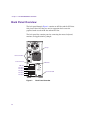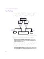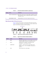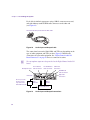
1
®
™
Avid Nitris DNA
Setup Guide
®
for the HP Workstation xw8000 System
®
on Windows XP
m a k e m a n a g e m ove | m e d i a ™
Avid
®
Copyright and Disclaimer
Product specifications are subject to change without notice and do not represent a commitment on the part
of Avid Technology, Inc. The software described in this document is furnished under a license agreement.
You can obtain a copy of that license by visiting Avid's Web site at www.avid.com. The terms of that license
are also available in the product in the same directory as the software. The software may not be reverse
assembled and may be used or copied only in accordance with the terms of the license agreement. It is
against the law to copy the software on any medium except as specifically allowed in the license
agreement.
No part of this document may be reproduced or transmitted in any form or by any means, electronic or
mechanical, including photocopying and recording, for any purpose without the express written permission
of Avid Technology, Inc.
Copyright © 2003 Avid Technology, Inc. and its licensors. All rights reserved.
The Avid DS and Avid DS Nitris application uses JScript and Visual Basic Scripting Edition from Microsoft
Corporation.
Attn. Government User(s). Restricted Rights Legend
U.S. GOVERNMENT RESTRICTED RIGHTS. This Software and its documentation are “commercial
computer software” or “commercial computer software documentation.” In the event that such Software or
documentation is acquired by or on behalf of a unit or agency of the U.S. Government, all rights with
respect to this Software and documentation are subject to the terms of the License Agreement, pursuant to
FAR §12.212(a) and/or DFARS §227.7202-1(a), as applicable.
Trademarks
888 I/O, Adrenaline, AirPlay, AirSPACE, AirSPACE HD, AniMatte, AudioSuite, AudioVision, AutoSync, Avid,
Avid DNA, AVIDdrive, AVIDdrive Towers, AvidNet, AvidNetwork, AVIDstripe, Avid Mojo, Avid Unity,
Avid Xpress, AVoption, AVX, CamCutter, ChromaCurve, ChromaWheel, DAE, D-Fi, D-fx, Digidesign,
Digidesign Audio Engine, Digidesign Intelligent Noise Reduction, DigiDrive, Digital Nonlinear Accelerator,
DigiTranslator, DINR, D-Verb, Equinox, ExpertRender, FieldPak, Film Composer, FilmScribe, FluidMotion,
HIIP, HyperSPACE, HyperSPACE HDCAM, IllusionFX, Image Independence, Intraframe, iS9, iS18, iS23,
iS36, Lo-Fi, Magic Mask, make manage move | media, Marquee, Matador, Maxim, MCXpress,
Media Composer, MediaDock, MediaDock Shuttle, Media Fusion, Media Illusion, MediaLog, Media Reader,
Media Recorder, MEDIArray, MediaShare, Meridien, MetaSync, NaturalMatch, Nearchive, NetReview,
NewsCutter, Nitris, OMF, OMF Interchange, OMM, Open Media Framework, Open Media Management,
ProEncode, Pro Tools, QuietDrive, Recti-Fi, RetroLoop, rS9, rS18, Sci-Fi, Softimage, Sound Designer II,
SPACE, SPACEShift, Symphony, the Avid|DS logo, Trilligent, UnityRAID, Vari-Fi, Video Slave Driver,
VideoSPACE, Xdeck, and XSI are either registered trademarks or trademarks of Avid Technology, Inc. in
the United States and/or other countries.
Adaptec is a trademark which may be registered in some jurisdictions. ATTO is a trademark of ATTO
Technology, Inc. FIRE GL is a trademark of ATI Technologies, Inc. HP is a registered trademark of
Hewlett-Packard Company. Mac OS is a trademark of Apple Computer, Inc., registered in the U.S. and
other countries. OpenGL is a registered trademark of Silicon Graphics, Inc. UNIX is a registered trademark
of The Open Group in the U.S. and other countries. Wacom is a registered trademark of Wacom Company,
Ltd. in the United States and/or other countries. Windows is either a registered trademark or trademark of
Microsoft Corporation in the United States and/or other countries. All other trademarks contained herein
are the property of their respective owners.
GOT FOOTAGE?
Editors — Filmmakers — Special Effects Artists — Game Developers — Animators — Educators —
Broadcasters — Content creators of every genre — Just finished an incredible project and want to
share it with the world?
Send us your reels and we may use your footage in our show reel or demo!*
For a copy of our release and Avid’s mailing address, go to www.avid.com/footage.
*Note: Avid cannot guarantee the use of materials submitted.
Avid Nitris DNA Setup Guide for the HP Workstation xw8000 System on Windows XP •
0130-05571-01 • September 2003
2
Contents
Using This Guide . . . . . . . . . . . . . . . . . . . . . . . . . . . . . . . . . . . . . 9
Who Should Use This Guide . . . . . . . . . . . . . . . . . . . . . . . . . . . . . . . . . . 9
Symbols and Conventions . . . . . . . . . . . . . . . . . . . . . . . . . . . . . . . . . . . 11
Using the Mouse, Pen, and Keyboard . . . . . . . . . . . . . . . . . . . . . . . 12
Customizing the Pen or Mouse . . . . . . . . . . . . . . . . . . . . . . . . . . . . 13
If You Need Help . . . . . . . . . . . . . . . . . . . . . . . . . . . . . . . . . . . . . . . . . . 13
Accessing the Online Documentation . . . . . . . . . . . . . . . . . . . . . . . 13
If You Have Documentation Comments. . . . . . . . . . . . . . . . . . . . . . 14
How to Order Documentation . . . . . . . . . . . . . . . . . . . . . . . . . . . . . 14
Avid Educational Services . . . . . . . . . . . . . . . . . . . . . . . . . . . . . . . . 14
Avid DS Customer Support . . . . . . . . . . . . . . . . . . . . . . . . . . . . . . . . . . 15
E-mail Support . . . . . . . . . . . . . . . . . . . . . . . . . . . . . . . . . . . . . . . . . 15
Web Support . . . . . . . . . . . . . . . . . . . . . . . . . . . . . . . . . . . . . . . . . . 15
FTP Support. . . . . . . . . . . . . . . . . . . . . . . . . . . . . . . . . . . . . . . . . . . 15
Mailing List . . . . . . . . . . . . . . . . . . . . . . . . . . . . . . . . . . . . . . . . . . . . 16
Chapter 1
Avid DS Overview and Site Preparation . . . . . . . . . . . . . . . . . 17
Package Contents . . . . . . . . . . . . . . . . . . . . . . . . . . . . . . . . . . . . . . . . . 17
Hardware . . . . . . . . . . . . . . . . . . . . . . . . . . . . . . . . . . . . . . . . . . . . . 17
Software. . . . . . . . . . . . . . . . . . . . . . . . . . . . . . . . . . . . . . . . . . . . . . 18
Documentation. . . . . . . . . . . . . . . . . . . . . . . . . . . . . . . . . . . . . . . . . 19
Site Planning . . . . . . . . . . . . . . . . . . . . . . . . . . . . . . . . . . . . . . . . . . . . . 21
Environmental Requirements. . . . . . . . . . . . . . . . . . . . . . . . . . . . . . 21
Electrical Requirements . . . . . . . . . . . . . . . . . . . . . . . . . . . . . . . . . . 22
Space Requirements . . . . . . . . . . . . . . . . . . . . . . . . . . . . . . . . . . . . 23
Additional Equipment . . . . . . . . . . . . . . . . . . . . . . . . . . . . . . . . . . . . . . . 25
Chapter 2
Avid DS Hardware Overview. . . . . . . . . . . . . . . . . . . . . . . . . . . 27
Back Panel Overview . . . . . . . . . . . . . . . . . . . . . . . . . . . . . . . . . . . . . . . 28
Workstation Boards . . . . . . . . . . . . . . . . . . . . . . . . . . . . . . . . . . . . . 29
3
Port Locations. . . . . . . . . . . . . . . . . . . . . . . . . . . . . . . . . . . . . . . . . . 31
Disk Subsystem . . . . . . . . . . . . . . . . . . . . . . . . . . . . . . . . . . . . . . . . . . . 32
System Inputs and Outputs. . . . . . . . . . . . . . . . . . . . . . . . . . . . . . . . . . . 33
Signal Flow . . . . . . . . . . . . . . . . . . . . . . . . . . . . . . . . . . . . . . . . . . . . . . . 34
Capture Mode . . . . . . . . . . . . . . . . . . . . . . . . . . . . . . . . . . . . . . . . . . 34
Playback Mode . . . . . . . . . . . . . . . . . . . . . . . . . . . . . . . . . . . . . . . . . 34
House Sync. . . . . . . . . . . . . . . . . . . . . . . . . . . . . . . . . . . . . . . . . . . . . . . 35
Tri-level Sync . . . . . . . . . . . . . . . . . . . . . . . . . . . . . . . . . . . . . . . . . . 35
Sync Topology . . . . . . . . . . . . . . . . . . . . . . . . . . . . . . . . . . . . . . . . . 36
Installing and Removing the Avid Fan. . . . . . . . . . . . . . . . . . . . . . . . . . . 37
Chapter 3
Assembling the System . . . . . . . . . . . . . . . . . . . . . . . . . . . . . . 39
Before Assembling the System . . . . . . . . . . . . . . . . . . . . . . . . . . . . . . . . 40
Connecting the Keyboard, Mouse, and Graphic Tablet . . . . . . . . . . . . . 41
Connecting the Monitors . . . . . . . . . . . . . . . . . . . . . . . . . . . . . . . . . . . . . 42
Connecting the Avid Nitris DNA . . . . . . . . . . . . . . . . . . . . . . . . . . . . . . . 43
Avid Nitris DNA Front Panel . . . . . . . . . . . . . . . . . . . . . . . . . . . . . . . 43
Nitris DNA Rear Panel . . . . . . . . . . . . . . . . . . . . . . . . . . . . . . . . . . . 44
Connecting the SCSI Local Storage Systems. . . . . . . . . . . . . . . . . . . . . 52
Avid MediaDock LVD . . . . . . . . . . . . . . . . . . . . . . . . . . . . . . . . . . . . 52
Avid MediaDock Ultra320 . . . . . . . . . . . . . . . . . . . . . . . . . . . . . . . . . 54
Connecting the Fibre Channel Local Storage. . . . . . . . . . . . . . . . . . 55
Avid Unity MediaNetwork . . . . . . . . . . . . . . . . . . . . . . . . . . . . . . . . . 56
Connecting the Machine Control Cable . . . . . . . . . . . . . . . . . . . . . . . . . 56
Connecting the USB-to-MIDI Converter . . . . . . . . . . . . . . . . . . . . . . . . . 57
Connecting Peripheral Devices. . . . . . . . . . . . . . . . . . . . . . . . . . . . . . . . 58
Video Connections . . . . . . . . . . . . . . . . . . . . . . . . . . . . . . . . . . . . . . 58
Audio Connections . . . . . . . . . . . . . . . . . . . . . . . . . . . . . . . . . . . . . . 59
Connecting the Application Key (Dongle) . . . . . . . . . . . . . . . . . . . . . . . . 61
Chapter 4
Rack Mounting the Avid Nitris DNA Enclosure. . . . . . . . . . . . 63
Equipment Environmental and Safety Guidelines. . . . . . . . . . . . . . . . . . 64
Installing the Avid Nitris DNA in a Rack . . . . . . . . . . . . . . . . . . . . . . . . . 64
Attaching the Rack Nuts to the Rack . . . . . . . . . . . . . . . . . . . . . . . . 65
Securing the Avid Nitris DNA in a Rack . . . . . . . . . . . . . . . . . . . . . . 66
4
Appendix A
Regulatory and Safety Notices . . . . . . . . . . . . . . . . . . . . . . . . . 69
Warnings and Cautions . . . . . . . . . . . . . . . . . . . . . . . . . . . . . . . . . . . . . 69
FCC Notice . . . . . . . . . . . . . . . . . . . . . . . . . . . . . . . . . . . . . . . . . . . . . . . 70
Canadian ICES-003 . . . . . . . . . . . . . . . . . . . . . . . . . . . . . . . . . . . . . . . . 70
European Union Notice . . . . . . . . . . . . . . . . . . . . . . . . . . . . . . . . . . . . . 71
Australia and New Zealand EMC Regulations . . . . . . . . . . . . . . . . . . . . 73
Taiwan EMC Regulations . . . . . . . . . . . . . . . . . . . . . . . . . . . . . . . . . . . . 74
Index . . . . . . . . . . . . . . . . . . . . . . . . . . . . . . . . . . . . . . . . . . . . . . 75
5
Figures
6
Figure 1
Avid DS System Configuration . . . . . . . . . . . . . . . . . . . . . 23
Figure 2
Back Panel Overview . . . . . . . . . . . . . . . . . . . . . . . . . . . . 28
Figure 3
Avid Nitris Base Board Connections. . . . . . . . . . . . . . . . . 30
Figure 4
ATTO Fibre Channel Connection . . . . . . . . . . . . . . . . . . . 31
Figure 5
Mouse, Keyboard, and Application Key Connections. . . . 31
Figure 6
Placing the Fan Into the System . . . . . . . . . . . . . . . . . . . 37
Figure 7
Lowering Fan Into Place. . . . . . . . . . . . . . . . . . . . . . . . . . 38
Figure 8
Plugging the Fan . . . . . . . . . . . . . . . . . . . . . . . . . . . . . . . 38
Figure 9
Connecting the Keyboard, Mouse, and Wacom Tablet . . 41
Figure 10
ATI FIRE GL X1 Board Slot Location . . . . . . . . . . . . . . . . 42
Figure 11
Avid Nitris DNA Front Panel . . . . . . . . . . . . . . . . . . . . . . . 43
Figure 12
Nitris DNA Rear Panel . . . . . . . . . . . . . . . . . . . . . . . . . . . 45
Figure 13
Connecting the Avid Nitris DNA . . . . . . . . . . . . . . . . . . . . 46
Figure 14
HD Video I/O Board Connectors . . . . . . . . . . . . . . . . . . . 47
Figure 15
Eight-Channel Audio I/O Board Connectors. . . . . . . . . . . 48
Figure 16
SD Video I/O Board Connectors . . . . . . . . . . . . . . . . . . . 49
Figure 17
SCSI Connections at the Rear of the System . . . . . . . . . 52
Figure 18
ATTO 3300 Fibre Channel Board Slot Location . . . . . . . . 55
Figure 19
dataMate Adapter . . . . . . . . . . . . . . . . . . . . . . . . . . . . . . . 56
Figure 20
USB-to-MIDI Converter . . . . . . . . . . . . . . . . . . . . . . . . . . 57
Figure 21
Connecting Video Devices . . . . . . . . . . . . . . . . . . . . . . . . 59
Figure 22
Audio Input and Output Cable . . . . . . . . . . . . . . . . . . . . . 60
Figure 23
Audio Input and Output Connections . . . . . . . . . . . . . . . . 60
Figure 24
Audio Monitoring Connection . . . . . . . . . . . . . . . . . . . . . . 61
Figure 25
Parallel Port Location . . . . . . . . . . . . . . . . . . . . . . . . . . . . 62
Figure 26
Positioning the Avid Nitris DNA . . . . . . . . . . . . . . . . . . . . 65
Figure 27
Attaching Rack Nuts onto the Rack Enclosure. . . . . . . . . 66
Figure 28
Installing an Avid Nitris DNA. . . . . . . . . . . . . . . . . . . . . . . 67
Tables
Table 1
System Hardware . . . . . . . . . . . . . . . . . . . . . . . . . . . . . . .18
Table 2
Avid DS Documentation. . . . . . . . . . . . . . . . . . . . . . . . . . .19
Table 3
Electrical Specifications . . . . . . . . . . . . . . . . . . . . . . . . . . .22
Table 4
Hardware Component Dimensions . . . . . . . . . . . . . . . . . .24
Table 5
Additional Equipment. . . . . . . . . . . . . . . . . . . . . . . . . . . . .25
Table 6
HP Workstation xw8000 Slot Configurations . . . . . . . . . . .29
Table 7
Disk Drive Information . . . . . . . . . . . . . . . . . . . . . . . . . . . .32
Table 8
System Inputs and Outputs . . . . . . . . . . . . . . . . . . . . . . . .33
Table 9
HD Formats . . . . . . . . . . . . . . . . . . . . . . . . . . . . . . . . . . . .35
Table 10
Avid Nitris DNA LEDs . . . . . . . . . . . . . . . . . . . . . . . . . . . .43
Table 11
HD Video I/O Board Identifiers . . . . . . . . . . . . . . . . . . . . .47
Table 12
Eight-Channel Audio I/O Board Identifiers. . . . . . . . . . . . .48
Table 13
SD Video I/O Board Identifiers. . . . . . . . . . . . . . . . . . . . . .50
7
8
Using This Guide
Congratulations on your purchase of an Avid® DS system. You can use
your system to create broadcast-quality output incorporating every
possible production element from full-speed, high-resolution footage to
multimedia artwork and animation, to computer-generated effects and
titling.
n
The documentation describes the features and hardware of all models.
Therefore, your system might not contain certain features and hardware
that are covered in the documentation.
Who Should Use This Guide
This guide is intended for anyone who is setting up an Avid DS Nitris
system for the first time, for anyone who might be moving a system, and
for anyone who might be attempting to solve problems that can arise with
the system hardware. This guide is not designed for someone who is
installing board sets in the system.
The information provided in this guide will help you to understand the
components that are part of a system, to connect the components for proper
system functionality, to configure and test the system after installation, and
to troubleshoot basic problems that can arise during daily operation.
Using This Guide
The Contents that precedes this section lists the topics included in the
guide. They are presented with the following overall structure:
•
Chapter 1, “Avid DS Overview and Site Preparation,” provides an
overview of the Avid Nitris DNA hardware, software, and
documentation included with your Avid DS Nitris workstation and the
information you need to prepare your site for the Avid Nitris DNA
system.
•
Chapter 2, “Avid DS Hardware Overview,” provides an overview of
the Avid Nitris DNA hardware included with your Avid DS Nitris
workstation.
•
Chapter 3, “Assembling the System,” provides the instructions you
need to assemble the Avid DS system.
•
Chapter 4, “Rack Mounting the Avid Nitris DNA Enclosure,” provides
the instructions for installing the Avid Nitris DNA enclosure in an
industry-standard rack.
•
Appendix A, “Regulatory and Safety Notices,” provides regulatory
and safety notices for the system.
An Index at the end of this guide helps you locate the information you
need.
10
Symbols and Conventions
Symbols and Conventions
Unless noted otherwise, the material in this document applies to the
Windows XP operating system. Avid DS Nitris documentation uses the
following symbols and conventions:
Symbol or
Convention
Meaning or Action
n
A note provides important related information, reminders,
recommendations, and strong suggestions.
c
A caution means that a specific action you take could cause
harm to your computer or cause you to lose data.
w
A warning describes an action that could cause you physical
harm. Follow the guidelines in this document or on the unit
itself when handling electrical equipment.
>
This symbol indicates menu commands (and subcommands)
in the order you select them. For example, File > Import
means to open the File menu and then select the Import
command.
t
This symbol indicates a single-step procedure. Multiple
arrows in a list indicate that you perform one of the actions
listed.
Margin tips
In the margin, you will find tips that help you perform tasks
more easily and efficiently.
Italic font
Italic font is used to emphasize certain words and to indicate
variables.
Courier Bold Courier Bold font identifies text that you type.
font
Bold font
Bold indicates a user interaction.
11
Using This Guide
Using the Mouse, Pen, and Keyboard
In Avid DS Nitris, you can use a two-button mouse (with wheel) or a pen
and tablet. The left and right mouse buttons perform different operations.
Unless otherwise stated, use the left mouse button.
The mouse and pen operate slightly differently. All the procedures in this
guide are documented for the mouse. You can, however, easily use a pen or
the keyboard. The following table shows the terms relating to the mouse,
pen, and keyboard.
This Term
Means This with a Mouse Means This with a Pen
Click
Quickly click and release the
left mouse button. Always
use the left mouse button
unless otherwise stated.
Double-click Click the left mouse button
twice rapidly.
12
Tap the tablet once with the tip of
the pen, or touch the pen to the
tablet with enough pressure to
click.
Quickly tap the tablet twice in the
same screen pixel or press the F5
key to go from single to doubleclick.
Right-click
Quickly click and release the Press the top portion of the switch
right mouse button.
on the side of the pen or press the
F6 key to go from left to rightclick.
Drag
Click and hold the left mouse Press the pen to the tablet while
button or the wheel while you moving the pen.
move the mouse.
Alt+key,
Ctrl+key,
Shift+key,
etc.
Press and hold the first key while you press the second key. For
example, “Press Alt+F1” means to press and hold the Alt key
while you press the F1 key.
If You Need Help
Customizing the Pen or Mouse
By customizing the pen, you can adjust the click pressure, switch
functions, and other features. For information on customizing the pen,
refer to the documentation provided with your Avid DS Nitris system.
You can also customize the mouse. For example, you can select lefthanded configuration or change the double-click speed. For information on
customizing the mouse, refer to the Windows online Help.
If You Need Help
If you are having trouble using Avid DS Nitris:
1. Retry the action, carefully following the instructions given for that task
in this guide. It is especially important to check each step of your
workflow.
2. Check for the latest information that might have become available
after the documentation was published in one of two locations:
-
If release notes are available, they ship with your application.
-
If ReadMe files are available, they are supplied in your Avid
application folder. ReadMe files are also available from Help.
3. Check the documentation that came with your Avid application or
your hardware for maintenance or hardware-related issues.
4. See “Avid DS Customer Support” on page 15.
5. For Technical Support, please call 800-800-AVID (800-800-2843).
Accessing the Online Documentation
The online library contains all the Avid DS Nitris documentation in PDF
format. If it was installed on your workstation, you can access it from the
Help menu in Avid DS Nitris.
n
You will need Adobe® Acrobat® Reader® installed to view the
documentation online.
13
Using This Guide
To access the online library, do one of the following:
t
In Avid DS Nitris, select Help > Online Library.
t
Insert the Drivers CD into your CD-ROM drive, and select Online
Library from the main menu.
To install Adobe Acrobat Reader:
1. Insert the Drivers CD into your CD-ROM drive.
2. Select the required workstation and choose Utilities.
If You Have Documentation Comments
We’d appreciate any comments or suggestions you may have about the
Avid DS Nitris documentation.
Please e-mail your documentation comments to:
[email protected]
Include the title of the document, its part number, and the specific section
you are commenting on in all correspondence.
How to Order Documentation
To order additional copies of this documentation from within the
United States, call Avid Sales at 800-949-AVID (800-949-2843). If you
are placing an order from outside the United States, contact your local
Avid representative.
Avid Educational Services
For information on courses/schedules, training centers, certifications,
courseware, and books, please visit www.avid.com/training or call
Avid Sales at 800-949-AVID (800-949-2843).
14
Avid DS Customer Support
Avid DS Customer Support
The following sections describe various Avid DS Customer Support
options.
E-mail Support
The e-mail address for Avid DS Customer Support is:
[email protected].
You can use it for sending bug reports, usability questions, and avidds.cab
audit reports for system analysis. All e-mails are logged in the support
database and assigned a case number. Send one support request per e-mail.
n
It is mandatory that you include your SID number in the body of your
e-mail message for verification of your maintenance contract and case
logging, otherwise, response will be delayed.
Web Support
The Avid DS Customer Support and Download sections at
http://www.softimage.com/avidds provide quick access to a wide range
of resources from the Avid DS teams and user community. Downloads,
including presets, drivers, and Quick Fix Engineering (QFE), provide the
latest solutions for use with your Avid DS Nitris system. Online
documentation, tutorials, and Knowledge Base articles ensure that you get
the most out of your work with Avid DS Nitris. It's like having a dedicated
Avid DS Customer Support engineer sitting at your desk!
FTP Support
For troubleshooting purposes, an FTP server is available for uploading
large files for Avid DS Customer Support personnel to examine. You can
upload a project’s archive, media files, or other large piece of data. Simply
zip the files to upload and use a short name for easy retrieval, such as
archive.zip or Case274877.zip. You can use a Windows Command Prompt
or an FTP application to upload files to our server.
15
Using This Guide
Command Prompt Commands
Command
Description
Site access
ftp ftp.softimage.com [Enter]
Folder access
cd incoming [Enter]
User name
anonymous [Enter]
Password
“your e-mail address” [Enter]
Transfer mode
bin [Enter]
Upload command
Put “path:\file name” [Enter]
Once the file upload is complete, send an e-mail to [email protected]
to inform Avid DS Customer Support as there is no automatic notification
when a file is uploaded on the FTP server. Please provide the complete and
exact file name (case sensitive) to retrieve.
Mailing List
Although the Avid DS mailing list is frequently monitored by Avid
employees, it is not part of the official support channels. You are invited to
send your support requests to any of the above channels when required.
If you have an e-mail account, you can join the worldwide network of
Avid DS users exchanging ideas. The mailing list has proven to be quite
useful for users, with a constant stream of new subscribers.
To subscribe, send an e-mail to [email protected] with the
following text in the body of your message: subscribe ds. You can get
further information on using the automated list server by e-mailing
[email protected] with “help” as your message.
You can also go to http://www.avid.com/support/forums.html, which is
also a great source of information on the Avid Web site for Avid DS.
16
Chapter 1
Avid DS Overview and Site
Preparation
This chapter provides an overview of the Avid DS hardware, software, and
documentation included with your Avid DS for HP Workstation xw8000
system and the information you need to prepare your site for the Avid DS
hardware.
This chapter contains the following sections:
•
Package Contents
•
Site Planning
•
Additional Equipment
Package Contents
Your Avid DS system contains hardware, software, and documentation.
Hardware
After carefully unpacking the hardware, verify all of the items on the
packing slip before setting up your workstation. Make sure that you write
down the serial number of all the devices.
Chapter 1 Avid DS Overview and Site Preparation
A typical Avid DS system includes the hardware listed in Table 1.
Table 1
System Hardware
Device
Device, cables, and accessories
HP Workstation xw8000
Base unit, keyboard, mouse, two optical cables, power cable, and
rackmount kit (optional)
Flat-panel monitors (21-inch monitors Two 18-inch flat-panel monitors, two monitor cables and two
from previous Avid DS systems are also VGA to DVI adapters, and two power cables
supported)
Avid MediaDock™ LVD or
Avid MediaDock Ultra320
local storage system
MediaDock LVD or MediaDock Ultra320 enclosure with LVD or
Ultra320 shuttle drives and power cables
(Option) Avid MEDIArray II™ local
storage
Fibre Channel controller board, an Avid MEDIArray II enclosure
with a minimum of four Fibre Channel drives for standard
definition (SD) or eight drives for high definition (HD) storage,
and a power cord
(Option) Avid Unity™ MediaNetwork
Fibre Channel storage system
Fibre Channel controller board. Enclosures depend on the
Avid Unity MediaNetwork system ordered
Avid Nitris™ Digital Nonlinear
Accelerator (DNA)
Avid Nitris DNA, digital interlink cable, three audio harness
cables, and a power cable
Avid installs two PCI boards in the HP xw8000 system that
support the Avid Nitris DNA.
(Option) Wacom® tablet
Tablet, pen and stand, USB cable, and 4D mouse
DataMate RS-232 to RS-422
convertor for deck control
Convertor, an RS-232 cable, and an RS-422 cable
Software
Most of the software that you receive on CD-ROM is also installed on your
workstation’s hard drive.
n
18
Keep the Software, Drivers, and Recovery CD-ROMs in a safe place in
case you need to reinstall the software or any of the drivers.
Package Contents
The Avid DS software package contains:
•
Avid DS Software CD-ROM
•
Avid DS Drivers CD-ROM
•
An Avid DS Recovery CD-ROM for the xw8000 system
•
Software protection key (dongle)
Your xw8000 system comes with the following software components preinstalled:
n
•
Windows XP Professional and Windows XP Service Pack 1 software
•
Avid Nitris DNA software
•
Wacom Technology software
•
ATI FIRE GL™ X1 software
The documentation for the software components is also shipped with the
system.
Documentation
Table 2 describes the complete Avid DS documentation set.
Table 2
Avid DS Documentation
Document
Format
Version
Description
Release Notes
Online/Print
7.0
Describes known problems and provides
workarounds. Also describes and includes video
presentations of the new features in v7.0 of
Avid DS.
Setup Guide (this
document)
Online/Print
7.0
Provides an overview of the Avid DS system and
describes how to connect the different sections of
system.
19
Chapter 1 Avid DS Overview and Site Preparation
Table 2
Avid DS Documentation (Continued)
Document
Format
Version
Description
Installation &
Administration Guide
Online/Print
7.0
Provides information on installing and upgrading
the current version of Avid DS and its components.
Also contains workstation administration tasks and
troubleshooting information.
Getting Started Guide
Online/Print
7.0
Contains quick step-by-step instructions to help you
get started on the basic post-productions tasks.
Compositing &
Effects Guide
Online/Print
7.0
Describes the basic types of effects in Avid DS and
shows you how to apply them to your media.
There’s also information on when and how to
process effects.
Capture and Output
Guide
Online/Print
7.0
Describes the processes of capturing material into
the Avid DS system and outputting a finished
sequence.
Editing Guide
Online/Print
7.0
Describes the work processes of Avid DS. It shows
you how to work with your media and perform basic
and advanced editing.
Help
Online
7.0
Contains the complete set of task and reference
information on Avid DS.
Reference Guide
Online
7.0
Contains printable reference information on layouts,
views, parameters in property editors and dialog
boxes, and commands in toolbars and pop-up menus
Keyboard Shortcuts
Online
7.0
Contains all the Avid DS keyboard shortcuts. You
can print it and slide it under the cover sheet of your
graphic tablet.
Online Library
Online
7.0
The complete set of Avid DS books in Acrobat PDF
format with a search index across all books.
Vendor documentation
Print
—
Guides from the vendors of the various hardware
and software components that comprise your
Avid DS workstation.a
a. For details on setting up, handling, and maintaining these components, see the documentation included with
each of them.
20
Site Planning
Site Planning
When preparing your site, you must consider the environmental, electrical,
and space requirements for your Avid DS workstation, as well as any
additional equipment that you may need to purchase and its requirements.
Environmental Requirements
The site you choose for your Avid DS workstation should meet the
following environmental requirements:
•
Clean and dust free
•
Free from significant temperature or humidity changes
•
Sturdy, level, and not subject to vibration
•
Away from radio frequency emissions, high-traffic, or high-noise areas
•
Provides adequate space in front of and behind the workstation
components, so that you can connect cables and service your
workstation. This also provides adequate airflow for cooling.
•
A minimum clearance of 3 inches (7.6 cm) for the side and back panels
of the deskside base unit
•
A table (or other surface) that is at least 60 inches wide by 48 inches
deep (150 cm × 120 cm) for the editing workstation
21
Chapter 1 Avid DS Overview and Site Preparation
Electrical Requirements
Your site should meet the following electrical requirements:
n
•
Adequate power for each workstation component, so that extension
cords are not needed.
•
At least two 15-amp circuits available: one for the workstation, Nitris
DNA, and accessories and one for the Avid MediaDock LVD storage
system.
•
Site is away from major electrical equipment, such as motors, air
conditioners, or elevators.
•
Site is not subject to static electrical buildup.
•
Uses an uninterruptible power supply (UPS) to protect your
workstation from sudden power surges or losses, and to save you from
the resulting loss of work.
Plug only your Avid DS equipment into the power strip. Do not plug in
coffee makers, radios, lights, or other such devices.
Table 3 describes the electrical specifications for the Avid DS system.
Table 3
Electrical Specifications
Component
Voltage
Frequency
HP Workstation xw8000
100 to 250 V ac auto-ranging
50 to 60 Hz
Monitors
100 to 250 V ac
50 to 60 Hz
Avid Nitris DNA
100 to 240 V ac
50 to 60 Hz
Avid MediaDock LVD and
Avid MediaDock Ultra320 storage systems
90 to 264 V ac
50 to 60 Hz
Avid MEDIArray Fibre Channel storage
(included with SD version of Avid DS only)
100 to 240 V ac
50 to 70 Hz
Wacom tablet
120 V ac (North America)
220 V ac (International)
60 Hz
22
Site Planning
Space Requirements
Your workstation includes either a tower or rackmount base unit, the video
storage array, and two flat-panel monitors. You can place the workstation
base unit and the video storage enclosure next to your work area or in a
rack as shown in Figure 1.
n
You can also monitors from previous Avid DS systems.
HD or NTSC/PAL
video monitor
Left monitor
Right monitor
Avid Nitris DNA
HP Workstation
xw8000
Speaker
Speaker
a
0
-6
IN
Nitris
HD
SD
HD
ANA REF
SD
REF LOCK
PULL
DOWN
LTC
DIG
SDI
-18
ANA
-42
1
2
3
4
5
6
7
8
9
10
11
12 13
14 15
16
VIDEO
0
OUT
-6
-18
-42
Wacom tablet
Keyboard
Mouse
Avid MediaDock or
MEDIArray storage
Figure 1
Avid DS System Configuration
The speakers and video monitor are purchased separately. The video
monitor and the computer monitors should be placed at least 12 inches
(30 cm) apart. Placing them closer together may cause synchronization
interference on the computer monitors.
If you purchase the optional rackmount kit for the base unit, it mounts in a
standard 19-inch (48.26 cm) equipment rack. The Avid Nitris DNA,
MEDIArray, and MediaDock LVD storage system can also be mounted in
the same or another equipment rack. For information on mounting the Avid
Nitris DNA, see Chapter 4.
23
Chapter 1 Avid DS Overview and Site Preparation
Table 4 lists the dimensions of the major hardware components.
Table 4
Hardware Component Dimensions
Dimensions
(Inches)
Dimensions
(Centimeters)
HP Workstation xw8000
Rackmount configuration — Rack Units: 5
Height: 17.7
Depth: 20.3
Width: 8.3
Height: 44.9
Depth: 51.5
Width: 21.0
18-inch flat-panel monitors (with stand)
Height: 15.9
Width: 15.7
Depth: 7.9
Height: 40.3
Width: 39.8
Depth: 7.4
Avid Nitris DNA
Rackmount configuration — Rack Units: 3
Height: 5.3
Width: 17.6
Depth: 13
Height: 13.5
Width: 44.7
Depth: 33.02
Avid MediaDock Ultra320
Tower configuration
(SD and HD version of Avid DS only)
Height: 21.5
Width: 10.5
Depth: 21.5
Height: 54.6
Width: 26.7
Depth: 54.6
Avid MediaDock Ultra320
Rackmount configuration — Rack Units: 2
(SD and HD version of Avid DS only)
Height: 3.5
Width: 17.6
Depth: 20.3
Height: 89
Width: 44.7
Depth: 51.5
Avid MediaDock LVD
Tower configuration
Height: 18.8
Width: 10.5
Depth: 17.6
Height: 47.7
Width: 26.7
Depth: 44.7
Avid MediaDock LVD
Rackmount configuration — Rack Units: 2
Height: 5.3
Width: 17.6
Depth: 17.4
Height: 13.5
Width: 44.7
Depth: 44.2
Avid MEDIArray
Tower configuration
(SD version of Avid DS only)
Height: 26.8
Width: 9.8
Depth: 29.4
Height: 68.0
Width: 24.9
Depth: 74.7
Avid MEDIArray
Rackmount configuration — Rack Units: 3
(SD version of Avid DS only)
Height: 6.1
Width: 17.5
Depth: 24.0
Height: 15.45
Width: 44.5
Depth: 60.9
Wacom tablet
Width: 9.0
Depth: 12.0
Width: 22.9
Depth: 30.5
Hardware component
24
Additional Equipment
Additional Equipment
Table 5 lists he additional peripherals and cables required for a typical
Avid DS workstation.
Table 5
Additional Equipment
Device
Description
House sync generator
The house sync must have the same video format as
your video equipment, as well as the project that you
create in Avid DS.
You will need a tri-level sync generator for HD
projects.
Video monitor
HD or NTSC/PAL
HD video cable
Use high-quality video cable certified for HDTV.
Videotape recorder
(VTR)
VTRs connect to the base unit through an RS-422
cable and RS-232 signal converter.
For a list of approved HD VTRs, contact your Avid DS
reseller.
Video distribution
amplifier
Distributes the house sync signal between separate
devices including the Avid Nitris DNA equipment.
Digital waveform
monitor
Measures the luminance and chrominance video
signals
Speakers and amplifier
Analog and/or digital audio equipment and converters
for converting audio signals
USB-MIDI
The USB port provides control of external controllers,
such as the JL Cooper MCS-3800. MIDI control
requires a separately purchased cable and the proper
MIDI driver.
25
Chapter 1 Avid DS Overview and Site Preparation
26
Chapter 2
Avid DS Hardware Overview
This chapter provides an overview of the Avid DS hardware included with
your Avid DS workstation.
This chapter contains the following sections:
•
Back Panel Overview
•
Disk Subsystem
•
System Inputs and Outputs
•
Signal Flow
•
House Sync
•
Installing and Removing the Avid Fan
Chapter 2 Avid DS Hardware Overview
Back Panel Overview
The back panel shown in Figure 2 contains an AGP slot and five PCI slots.
Only four of these PCI slots are used as expansion slots because the
graphics board uses the AGP slot and one PCI slot.
The back panel also contains ports for connecting the mouse, keyboard,
monitors, and application key (dongle).
Dongle
Port connections
SCSI Channel A
Monitors
AGP slot
PCI Slot 1
PCI Slot 2
PCI Slot 3
SCSI Channel B
PCI Slot 4
PCI Slot 5
Figure 2
28
Back Panel Overview
Back Panel Overview
Workstation Boards
Figure 2 shows the location of boards in the expansion slots of a deskside
workstation.
Table 6 describes the location and function of each expansion board
installed in the workstation. Expansion boards are installed in the
workstation’s PCI and AGP slots. For details on board specifications and
configuration, see the vendor documentation.
Table 6
HP Workstation xw8000 Slot Configurations
Slot
Board Information
Description
AGP slot
ATI FIRE GL X1 256 MB
graphics boarda
Processes input from the Avid Nitris Base board,
handles OpenGL® processing, and outputs video
signal to workstation monitor(s)
PCI slot 1
Empty
None (space used by ATI FIRE GL X1)
PCI slot 2
Not used
None
PCI slot 3
Avid Nitris Base board
Processes video capture, playback I/O, and
hardware effects for the Avid Nitris DNA and
routes video to the ATI FIRE GL X1 graphics
board
PCI slot 4
Avid Nitris Codec board
Performs the HD compression and 10-bit formats
for the Avid Nitris Base board.
PCI slot 5
ATTO™ optical Fibre Channel Processes input and output to the Fibre Channel
storage on Avid Unity™ MediaNetwork or local
board when connected to
Avid Unity™ MediaNetwork storage.
(SD) or local storage (SD or
HD)
a. On a rack mount workstation, the AGP slot is to the left, and the PCI slot 5 is to the right when
viewing the back of the workstation base unit.
29
Chapter 2 Avid DS Hardware Overview
Rear SCSI Connectors
SCSI channels at the rear of the system, A and B, replace the Adaptec™
39160 SCSI board used in previous Avid DS systems. These channels
allow you to use the HD version of Avid DS with Avid MediaDock LVD
Avid MediaDock Ultra series, or other Avid DS supported SCSI storage
devices.
n
As drive size and drive speed improve, some Fibre Channel devices and
LVD shuttles will be available for use, while some might be discontinued.
For more product information contact Avid Sales and Product Information
at 800-949-2843.
For more information on a specific expansion board, see the
manufacturer’s documentation.
Avid Nitris Base Board Connections
The following illustration shows the connections on the Avid Nitris Base
board. For information on connecting your video and audio equipment to
the Avid Nitris Base board, see “Connecting Peripheral Devices” on
page 58.
ris
Nit e
s
Ba
The Avid Nitris Base board is labeled
Digital interlink cable (Avid Nitris Base board)
Figure 3
c
30
Avid Nitris Base Board Connections
There is a similar connector on the Nitris Codec board which is
currently not used. Make sure you connect the digital interlink cable
to the board labeled “Nitris Base.”
Back Panel Overview
ATTO Optical Fibre Channel Board Connector
Figure 4 shows the connector on the ATTO optical Fibre Channel board.
This is the storage adapter included with SD versions of Avid DS that use
the Avid Unity MediaNetwork or SD or HD versions of Avid DS that use
local storage. For more information on the ATTO board, see the
instructions that ship with Avid Unity MediaNetwork.
Figure 4
ATTO Fibre Channel Connection
Port Locations
The back panel also contains ports for connecting the mouse, keyboard,
and application key (dongle). See Figure 5.
Mouse
Keyboard
Dongle
Figure 5
Mouse, Keyboard, and Application Key Connections
31
Chapter 2 Avid DS Hardware Overview
Disk Subsystem
In a standard configuration, one Integrated Drive Electronics (IDE)
disk drive is installed in the base unit, and eight SCSI disk drives are
installed in the Avid MediaDock LVD or 12 SCSI disk drives in a
MediaDock Ultra320. The system disk drive is formatted with two
partitions for storing operating system files, project files, and audio files.
The Avid MediaDock LVD drives are formatted as a striped volume for
video file storage.
Disk striping is a hardware capability that speeds up data I/O from disk
storage. The workstation divides the data into pieces, and spreads the
pieces across the disks in the striped volume. Because the workstation
transfers data to multiple drives in smaller chunks than would be
transferred to a single drive, the data transfer rate is accelerated.
Table 7 summarizes disk drive information for a standard configuration.
Table 7
Disk Drive Information
Drive Label
Description
Contents
Format
C
System
A partition of the primary system disk
Operating system NTFS
software
D
Video storage
Local SCSI or local Fibre Channel storage Video files
for SD or HD versions
NTFS
Avid Unity MediaNetwork
Workspaces
Avid Unity file
system
F
Projects
A partition of the primary system disk
Audio and
project-related
files
NTFS
G
DVD-ROM
—
—
—
32
System Inputs and Outputs
System Inputs and Outputs
Table 8 describes the system inputs and outputs. For instructions on
connecting peripherals and various video equipment to your workstation,
see Chapter 3.
Table 8
System Inputs and Outputs
Input/output
Description
Video Input
HD and SD SDI via BNC connectors
SD component via BNC connectors
SD composite via BNC connector
SD S-Video via an S-Video connector
Video Output
HD and SD SDI via BNC connectors
HD and SD component via BNC connectors
SD composite via BNC connectors
SD S-Video via an S-Video connector
Audio Analog Input
8 analog audio input channels with adjustable gain controls
Audio Analog Output
8 analog audio output channels with adjustable gain controls
Audio Digital I/O
8 AES/EBU digital input and output channels
Optical Digital I/O
ADAT and S/PDIF multichannel optical digital interface (ODI)
USB
Used to interfaces with a USB-to-MIDI converter
The MIDI/game port (located on the USB-to-MIDI converter) provides
MIDI control of external controllers, such as the JL Cooper MCS-3800.
MIDI control requires a separately purchased cable and the proper
MIDI driver.
Sync Input
SD sync input via BNC connector
HD tri-level sync input via BNC connector
RS-232 Remote
DB-9 connector that connects the RS-232 to RS-422 convertor. Use the
supplied cable only
SCSI rear connectors
68-pin connectors for the Avid MediaDock LVD and Avid MediaDock
Ultra320 storage systems
33
Chapter 2 Avid DS Hardware Overview
Signal Flow
The following sections provide an overview of the signal flow during
capture and playback. The Avid DS software controls the process.
Capture Mode
Capture mode lets you use Avid DS to capture video and audio from the
VTR.
•
The video output of the VTR goes through the Avid Nitris DNA to the
Nitris Base board, then to the Nitris Codec board, and from there to the
video storage array.
•
The video output of the Nitris Base board goes to the graphics board
and then to the workstation monitors, where it is displayed as video-ina-window.
•
The control signal from the serial port goes to the VTR to control
device operation (the supplied RS-232/RS-422 convertor and cable
must be connected to the workstation).
•
The sync signal from the house sync goes through the Avid
Nitris DNA to the Nitris Base board.
Playback Mode
Playback mode lets you use Avid DS to record video on the VTR.
34
•
The video stored on the video storage array goes through the Nitris
Codec board, the Nitris Base board, the Avid Nitris DNA, and then
goes to the VTR and video monitor.
•
The video output of the Avid Nitris Base board goes to the graphics
board and then to the workstation monitors, where it displays as videoin-a-window. It is also sent back to the Avid Nitris DNA for a Client
monitor.
•
The control signal from the serial port goes to the VTR to control
device operation.
•
The sync signal from the house sync goes through the Avid
Nitris DNA.
House Sync
House Sync
Whenever you use more than one video device, you must have video
synchronization. If the devices are not in sync, a monitor will show rolling,
tearing, or incorrect colors in the picture whenever you transfer the video
between devices.
A sync generator or house sync provides the synchronizing composite
signal to all other devices (video and audio) that must lock to the main
video program. This analog composite reference video signal, called
“color black” or “black-burst” video, is a timing pulse that is added to a
composite video signal and contains horizontal, vertical, and color
synchronizing information.
Tri-level Sync
In the case of HD video devices, you need a tri-level sync. Tri-level sync
could be considered synonymous to black-burst video in that it is simply
the reference synchronizing information from the facility’s master
generator.
Each HD format needs a specific tri-level sync. You must use the proper
tri-level sync to synchronize your VTR and the Nitris DNA video
subsystem for all the HD formats supported by Avid DS.
n
To make sure the configuration you are using is properly synced, read the
documentation that ships with your video subsystem.
Table 9 shows the HD formats currently supported by Avid DS and their
relevant frame rates.
Table 9
HD Formats
HD format
Supported frame rates (fps)
1080i Interlaced
30.00 fps, 29.97 fps, 25.00 fps
1080Psf Progressive 30.00 fps, 29.97 fps, 25.00 fps, 24.00 fps, 23.976 fps
720 Progressive
59.94 fps, 60 fps
35
Chapter 2 Avid DS Hardware Overview
Sync Topology
When you sync analog and digital video/audio devices, it is always
preferable to feed every component with a separate black-burst or tri-level
sync signal in a star pattern. Avoid looping the reference signal, by
terminating any unused loop out with a 75 ohm terminator.
Master house
sync generator
NTSC/PAL
black-burst
generator
Tri-level sync
generator
Video
Distr.
Amp
To analog
Reference In
To SD Sync
SD VTR
Video
Distr.
Amp
To HD Tri-level
Sync
Avid Nitris DNA
To HD
Reference In
HD VTR
A typical star pattern sync topology
You also need to verify the following to make sure your topology is
correct:
36
•
Distance between distribution Amplifier (DA): If your DA feeds
multiple machines that are far apart, the stability and strength of the
signal it sends will be crucial.
•
Quality of the devices: A good DA in a star pattern topology will be
necessary to ensure that every device is properly referenced. A tri-level
sync signal could be distributed by an analog video distribution
amplifier.
•
Analog video routing switchers: The Nitris DNA has separate inputs
for the SD and HD sync, consider using an analog routing switcher to
select between the various tri-level sync signals.
Installing and Removing the Avid Fan
Installing and Removing the Avid Fan
The documentation that ships with the HP Workstation xw8000 system
explains how to install optional equipment. However, Avid requires an
extra fan in the HP Workstation xw8000 system for cooling the Avid board
set. The following procedure describe how to install the fan Avid has added
to the HP Workstation xw8000 system. Reverse the procedure for
removing the fan.
c
Before you install or remove the fan, you must make sure the system
was turned off in a proper manner, the power cord is removed from
the rear of the system, and you follow the proper grounding
techniques.
To install and remove the fan:
1. Lay the system on its right side.
2. Unlock the left side cover using the keys attached to the rear of the
system.
3. Remove the side cover by pulling out the latch to release the cover and
removing it from the system.
4. Place the fan into the two slots located at the rear of the system. Make
sure that the round SCSI cable is under the higher portion of the fan
(see Figure 6).
Slots
High portion of fan
Round SCSI cable
Figure 6
Placing the Fan Into the System
37
Chapter 2 Avid DS Hardware Overview
5. Lower the other end of the fan, pushing it down and towards the rear of
the system until you have a pressure fit, carefully watching for the
cables on the side of the system (see Figure 7).
Cables
Figure 7
Lowering Fan Into Place
6. Connect the power plug (see Figure 8).
n
Avid uses one of the power plugs available for internal disks.
Fan plug
Figure 8
Plugging the Fan
7. Reverse the procedure for removing the fan.
38
Chapter 3
Assembling the System
This chapter provides the instructions you need to assemble the Avid DS
system. This chapter contains the following sections:
•
Before Assembling the System
•
Connecting the Keyboard, Mouse, and Graphic Tablet
•
Connecting the Monitors
•
Connecting the Avid Nitris DNA
•
Connecting the SCSI Local Storage Systems
•
Connecting the Machine Control Cable
•
Connecting the USB-to-MIDI Converter
•
Connecting Peripheral Devices
•
Connecting the Application Key (Dongle)
Chapter 3 Assembling the System
Before Assembling the System
Before setting up your system, see the Release Notes to make sure that
there are no changes, additions, or deletions to the procedures in
this chapter.
The required expansion boards are installed and configured for Avid DS.
You should not remove or modify these boards.
For detailed instructions on setting up the base unit hardware, see the setup
sheet provided with the HP Workstation xw8000. For a rackmount
workstation, you must install the base unit into a standard rack before
connecting the hardware.
To prevent equipment damage that may be caused by static electricity, do
all of the following before making any connections:
40
•
Turn off all devices.
•
Always use anti-static prevention.
•
Always connect devices to a properly grounded outlet.
•
Touch the metal casing of the device before handling the boards.
Connecting the Keyboard, Mouse, and Graphic Tablet
Connecting the Keyboard, Mouse, and Graphic Tablet
The keyboard and mouse come with attached cables for connecting them
to the back panel of your workstation. The Wacom graphic tablet comes
with a USB cable. Figure 9 shows the keyboard, mouse, and Wacom tablet
connections on a deskside workstation. For more information, see the
Wacom documentation.
Keyboard
Mouse
Wacom
tablet
Figure 9
Connecting the Keyboard, Mouse, and Wacom Tablet
To connect the keyboard and mouse:
1. In the base unit, connect the keyboard to the top-left or bottom
mini-DIN port.
2. Connect the mouse to the top-right or top mini-DIN port in the base
unit.
n
On a rackmount workstation, the keyboard port is on the bottom when
viewing the back of the workstation base unit and the mouse is to the top.
To connect the Wacom tablet:
t
Connect the USB cable from the Wacom tablet to one of the USB ports
on the back panel of the base unit (the tablet receives power through
the USB port). If needed, the Wacom tablet can also plug into one of
the front USB ports on the workstation.
41
Chapter 3 Assembling the System
Connecting the Monitors
Your workstation comes with two monitors for Avid DS. You can
purchase either standard high-resolution flat-panel monitors or VGA
monitors. The monitors connect to the ATI FIRE GL X1 board (see
Figure 10). The ATI FIRE GL X1 board takes up two slots in the xw8000
system: the AGP slot and PCI slot 1.
Connector for
left monitor
Connector for right monitor
AGP slot
PCI slot 1
Figure 10
n
ATI FIRE GL X1 Board Slot Location
On a rackmount workstation, the ATI FIRE GL X1 board is to the left when
viewing the back of the workstation base unit.
Each monitor comes with a video cable and a power cable. Depending
upon the monitor, you might receive a VGA-to-DVI adapter. Avid
recommends that you use the DVI connectors on the monitor if available.
For more information regarding the ATI FIRE GL X1 board and monitors,
see the documentation.
The driver for the ATI FIRE GL X1 board should be installed on your
system, but is also located on the Avid DS Drivers CD-ROM. Unique
video property settings and system BIOS are used in your Avid DS Nitris
system. For more information consult, your Avid representative.
To connect the monitors:
1. Verify that the power switches on the monitor and the base unit are in
the Off position, and then connect these devices to a power source.
2. Attach one end of the cable to the monitor. Use adapter if needed.
3. Attach the other end of the cable to the appropriate DVI connector as
shown in Figure 10. Use adapter if needed.
42
Connecting the Avid Nitris DNA
Connecting the Avid Nitris DNA
The Avid DS workstation also includes the Avid Nitris DNA, which
provides the high definition and standard definition input and output from
your workstation. The front panel of the Nitris DNA has several status
LEDs, audio meters, and a power switch.
Avid Nitris DNA Front Panel
Figure 11 and Table 10 show and describe the Avid Nitris DNA LEDs, and
power switch.
Status LEDs
Audio meters
a
0
-6
IN
Nitris
HD
SD
HD SD
ANA REF REF LOCK
PULL
DOWN
LTC
DIG SDI
-18
ANA
-42
1
2
3
4
5
6
7
8
9
10 11 12 13 14 15 16
VIDEO
0
OUT
-6
-18
-42
Power switch
LED
Power LEDs
LEDs
Figure 11
Avid Nitris DNA Front Panel
Table 10
Avid Nitris DNA LEDs
Status When Lit
VIDEO
HD
The Nitris DNA is in High Definition (HD) mode (as opposed to SD). The light will be
illuminated when the system is set to ingest HD source media and the signal is present
from the source.
SD
The Nitris DNA is in Standard Definition (SD) mode. The light will be illuminated when
the system is set to ingest SD source media and the signal is present from the source.
43
Chapter 3 Assembling the System
Table 10
Avid Nitris DNA LEDs (Continued)
LED
Status When Lit
HD REF
Blinks when a High Definition Reference signal is connected and constantly on when the
Nitris DNA is locked to the incoming Reference signal.
SD REF
Blinks when a Standard Definition Reference signal is connected and constantly on when
the Nitris DNA is locked to the incoming Reference signal.
Lock
The Nitris DNA has a valid house sync input signal and is locked to it (for capture). This
LED blinks if it detects a sync signal that is not valid.
AUDIO
Pull Down
Lit when Pull Down is selected in the application.
LTC
Lit when LTC IN is present on the input to the Nitris DNA.
DIG
Lit when a digital input is selected in the application.
SDI
Lit when a serial digital audio interface input is selected in the application.
ANA
Lit when an analog input is selected in the application.
Power LEDs
LEDs around the power button light when the Nitris DNA is on.
Yellow is displayed when no signal is detected from the Nitris Base board.
Green is displayed when the Nitris Base board signal is detected.
Nitris DNA Rear Panel
The Nitris DNA rear panel (see Figure 12) contains the following
video I/O and audio I/O boards:
44
•
HD Video I/O board — Provides HD SDI I/O, HD monitor,
HD component, and a HD trilevel sync connections for video
equipment.
•
Eight-channel audio I/O board — Provides two microphone inputs,
eight analog I/O channels, two S/PDIF audio I/O channels, eight
AES/EBU audio I/O channels, and eight channels of optical ADAT.
Connecting the Avid Nitris DNA
•
SD Video I/O board — Provides analog and digital I/O connections
for video equipment, and connects the Avid Nitris DNA to the system
using the digital interlink cable. It also provides locations for syncing
equipment to the Nitris DNA.
HD video I/O board
HD SDI IN
HD SDI OUT
OUT 1
Eight-channel I/O audio board
HD COMPONENT OUT
HD MONITOR OUT
OUT 2
Y
NITRIS HD
ANALOG AUDIO IN
S/P DIF
ANALOG AUDIO OUT
MIC 1
MIC 2
1
2
3
4
5
GAIN
6
7
8
1
2
3
4
5
6
7
Y
PB
PR
CV S-VIDEO
Y
PB
PR
OPTICAL
IN
OUT
8
SDI
CV 1
SD SYNC
AES/EBU
IN/OUT
OUT
ANALOG OUT
S-VIDEO
HD TRILEVEL
SYNC
DAE
OUT 1
IN
LTC
1
SYSTEM
CV 2
OUT 2
IN
OUT
2
SD video I/O board
Figure 12
n
MONITOR OUT
ANALOG IN
PR
DIGITAL AUDIO
IN
GAIN
PB
Power cord
connector
Nitris DNA Rear Panel
If you select a downconvert format, you can output HD playback and SD
downconvert simultaneous through the Avid Nitris DNA. As a result, you
can monitor SD output or create an SD master at the same time you are
outputting an HD master. Some HD media formats are not compatible with
SD resized outputs.
The back panel of the Nitris DNA shown in Figure 12 has several
connectors that provide the following:
•
Digital interlink cable transfers video signal data between the
workstation’s Avid Nitris Base board and the Avid Nitris DNA
•
HD video inputs from a VTR or other device
•
HD video outputs to VTRs or monitors
•
Standard definition video inputs from a VTR or other device
•
Standard definition video outputs to VTRs or monitors
45
Chapter 3 Assembling the System
•
Two tip/ring/sleeve (TRS) jacks on the SD video I/O board for audio
monitoring
•
SD sync or HD tri-level sync inputs for the incoming house sync signal
•
Monitoring inputs and outputs for composite, component (Y, Pb, and
Pr), and S-Video monitors, and SDI
To connect the Avid Nitris DNA to the workstation (see Figure 13):
1. Make sure that the power switch on the Nitris DNA is Off.
2. Attach the power cord to the power connector at the back of the
Nitris DNA and plug it into a power outlet.
3. Plug one end of the digital interlink cable into the SYSTEM connector
at the back of the Nitris DNA.
4. Plug the other end of the digital interlink cable into the digital interlink
connector on the Avid Nitris Base board.
5. Make sure both ends of the cable are secure.
HD SDI IN
HD SDI OUT
OUT 1
HD COMPONENT OUT
HD MONITOR OUT
OUT 2
Y
NITRIS HD
ANALOG AUDIO IN
ANALOG AUDIO OUT
GAIN
GAIN
S/P DIF
MIC 2
1
2
3
4
5
6
7
1
2
3
4
5
7
Y
PB
PR
CV S-VIDEO
Y
PB
PR
S-VIDEO
Power
connector
OPTICAL
IN
OUT
8
SDI
ANALOG OUT
CV 1
SD SYNC
AES/EBU
IN/OUT
OUT
6
HD TRILEVEL
SYNC
DAE
OUT 1
IN
LTC
1
SYSTEM
CV 2
OUT 2
IN
OUT
2
MONITOR OUT
ANALOG IN
8
PR
DIGITAL AUDIO
IN
MIC 1
PB
Avid Nitris DNA
System connector
Avid Nitris DNA
base board connector
Digital interlink cable
Figure 13
46
Connecting the Avid Nitris DNA
Connecting the Avid Nitris DNA
HD Video I/O Board Connectors
Figure 14 shows the connections on the HD video I/O board. Table 11
describes the function of each connector. You select which inputs to use
from the Capture tool when inputting. Use the Output tool to select the
outputs.
n
The HD Monitor and HD Component outputs cannot be used at the same
time. Select one of the two in the Output tool.
1
2
HD SDI IN
3
4
HD SDI OUT
OUT 1
5
HD MONITOR OUT
OUT 2
NITRIS HD
Figure 14
HD Video I/O Board Connectors
Table 11
HD Video I/O Board Identifiers
6
7
8
HD COMPONENT OUT
Y
PB
PR
HD TRILEVEL
SYNC
Number Label
Function
1
HD SDI IN
High-Definition Serial Digital Interface input, BNC connector.
2
HD SDI OUT 1
High-Definition Serial Digital Interface output number 1, BNC
connector.
3
HD SDI OUT 1
High-Definition Serial Digital Interface output number 2, BNC
connector.
4
HD MONITOR OUT
High-Definition component analog RGB video signal on a
15-pin connector: compatible with multisync computer
monitors.
5
Y, HD COMPONENT OUT
HD analog component video output, Y color difference signal,
BNC connector; connects to analog video input of a monitor or
waveform /vector.
6
PB, HD COMPONENT OUT HD analog component video output, PB color difference signal,
BNC connector; connects to analog video input of a monitor or
waveform /vector.
47
Chapter 3 Assembling the System
Table 11
HD Video I/O Board Identifiers (Continued)
Number Label
Function
7
PR, HD COMPONENT OUT HD analog component video output, PR color difference signal,
BNC connector; connects to analog video input of a monitor or
waveform /vector.
8
HD TRILEVEL SYNC
High-Definition video reference input for tri-level sync.
Eight-Channel Audio I/O Board Connectors
Figure 15 shows the connections on the eight-channel audio I/O board.
Table 12 describes the function of each connector. You select which audio
inputs to use from the Capture tool when inputting.
Gain adjustments
ANALOG AUDIO IN
S/P DIF
ANALOG AUDIO OUT
DIGITAL AUDIO
IN
GAIN
MIC 1
MIC 2
1
1
2
2
3
4
5
GAIN
6
7
8
3
1
2
3
4
4
5
AES/EBU
IN/OUT
OUT
6
7
OPTICAL
IN
OUT
8
5
6
7
Figure 15
Eight-Channel Audio I/O Board Connectors
Table 12
Eight-Channel Audio I/O Board Identifiers
8
9
Number
Label
Function
1
MIC 1
2
MIC 2
Microphone (MIC) inputs, two female XLR connectors. The
analog microphone connectors accept powered or 48 V
phantom power microphones. The audio input and
microphone are selected in the software.
3
ANALOG IN
Channels 1 - 8 Professional level audio input, 25-pin
DSUB connector; a color coded DB25 to XLR cable is
provided.
—
Gain
Gain controls for the 8 audio inputs.
48
Connecting the Avid Nitris DNA
Table 12
Eight-Channel Audio I/O Board Identifiers (Continued)
Number
Label
Function
4
ANALOG OUT
Channels 1 - 8 Professional level audio output, 25-pin
DSUB connector; a color coded DB25 to XLR cable is
provided.
—
Gain
Gain controls for the 8 audio outputs.
5
S/PDIF IN
S/PDIF digital input, white phono (RCA) jack.
6
S/PDIF OUT
S/PDIF digital output, red phono (RCA) jack.
7
AES/EBU IN/OUT
Channels 1 - 8 AES/EBU digital input and output, 25-pin
DSUB-connector; a color coded DB25 to XLR cable is
provided.
8
ADAT IN
8 optical channels input.
9
ADAT OUT
8 optical channels output.
SD Video I/O Board Connectors
Figure 16 shows the connections on the SD video I/O board. Table 13
describes the function of each connector.
10
SDI
ANALOG OUT
CV 1
SD SYNC
Y
PB
PR
CV
S-VIDEO
Y
PB
PR
S-VIDEO
20
16
DAE
OUT 1
IN
LTC
1
SYSTEM
CV 2
OUT 2
1
2
3
4
Figure 16
5
6
7
8
9
11
12
13
IN
15
17
OUT
18
2
19
MONITOR OUT
ANALOG IN
14
21
SD Video I/O Board Connectors
All analog video outputs are available during capture and playback to be
used as a client monitor.
49
Chapter 3 Assembling the System
Table 13
SD Video I/O Board Identifiers
Number Label
Function
1
SD SYNC
Standard-definition video reference (REF) input for a black burst
or house sync signal, BNC connector.
2
Y, ANALOG IN
(component)
SD analog component video input, Y luma, BNC connector;
connects to the Y video output of decks.
3
PB, ANALOG IN
(component)
SD analog component video input, PB color difference signal,
BNC connector; connects to the B-Y video output of decks.
4
PR, ANALOG IN
(component)
SD analog component video input, PR color difference signal,
BNC connector; connects to R-Y video output of decks.
5
CV, ANALOG IN
(composite)
Composite video input, BNC connector. Connects to analog video
output of decks.
6
S-VIDEO, ANALOG IN
S-Video input, 4-pin connector. Connects to analog video output
of decks.
7
Y, ANALOG OUT
(component)
SD analog component video output, Y luma, BNC connector;
connects to Y video input of decks. The component analog output
connectors can also be connected to a monitor or waveform/vector.
8
PB, ANALOG OUT
(component)
SD analog component video output, PB color difference signal,
BNC connector; connects to B-Y video input of decks. The
component analog output connectors can also be connected to a
monitor or waveform/vector.
9
PR, ANALOG OUT
(component)
SD analog component video output, PR color difference signal,
BNC connector; connects to R-Y video input of decks. The
component analog output connectors can also be connected to a
monitor or waveform/vector.
10
CV 1, ANALOG OUT
(composite)
Composite video output, BNC connector. Connects to analog
video input of decks or monitor.
11
CV 2, ANALOG OUT
(composite)
Composite video output, BNC connector. Connects to analog
video input of decks or monitor.
50
Connecting the Avid Nitris DNA
Table 13
Number Label
SD Video I/O Board Identifiers (Continued)
Function
12
S-VIDEO, ANALOG OUT Super-video output, 4-pin connector. Connects to analog video
input of decks.
13
SDI IN
Serial Digital Interface input, BNC connector.
14
SDI OUT1
Serial Digital Interface output number 1, BNC connector.
15
SDI OUT2
Serial Digital Interface output number 2, BNC connector.
16
DAE
Digital Audio Extraction (DAE) interface, 9-pin DSUB connector.
DAE will not be supported in the initial release of the Nitris DNA.
17
SYSTEM
Audio, video, and communication I/O connector from the Avid DS
system.
18
LTC IN
Longitudinal timecode input, female connector. Can be used in
place of 9-pin deck control when deck control is not required.
19
LTC OUTa
Longitudinal timecode output, male connector. Master clock used
to stripe tapes and synchronize systems to the house master clock
(SMPTE for NTSC, and EBU for PAL).
20
Monitor OUT 1
21
Monitor OUT 2
1/4-inch audio tip/ring/sleeve (TRS) jacks that each output one
channel (left/right) of audio to speakers. The audio feeding this
connection is from the incoming or outgoing audio.
TRS jack provides balanced professional level
c This
audio to your speaker system. Do not use 1/4 mono
cables in this connector, your output levels might be too
high.
a. Not available for use at this time.
51
Chapter 3 Assembling the System
Connecting the SCSI Local Storage Systems
Avid DS supports two standalone, local SCSI storage systems:
•
Avid MediaDock LVD
•
Avid MediaDock Ultra320
Both of these storage systems connect to the two SCSI channels at the rear
of the xw8000 system (see Figure 17) and must be striped to provide the
needed throughput. For striping information, see the Avid DS Installation
& Administration Guide.
SCSI channel A
SCSI channel B
Figure 17
n
SCSI Connections at the Rear of the System
The connections at the rear of the xw8000 system are HD68-pin
connectors. If you are going to use SCSI devices for standalone storage,
you must order the cables separately when you order your Avid DS system.
Avid MediaDock LVD
The Avid MediaDock LVD has eight slots for LVD shuttle drives. You can
use them in either single-bus or dual-bus configurations. The number of
MediaDock LVD enclosures you need depends upon how the devices are
configured. Avid DS only supports two configurations for the Avid
MediaDock LVD.
52
Connecting the SCSI Local Storage Systems
•
Single MediaDock LVD — For a single MediaDock configuration,
the Avid MediaDock LVD is used in a dual-bus configuration. In this
configuration, the slots are shared between bus A and bus B — for
example, the four top slots on SCSI bus channel A and the four bottom
slots on SCSI bus channel B. In this configuration you can have a
maximum of eight drives, four each on each SCSI bus.
•
Dual MediaDock LVD — If you need extra storage, you can connect
two Avid MediaDock LVD enclosures to your Avid DS workstation.
For the two-enclosure configuration, each Avid MediaDock is in a
single bus configuration. In this configuration, all eight slots are on
one bus in each Avid MediaDock and each MediaDock is connected to
a different SCSI channel. In this configuration, you can use a
maximum of 16 drives, 8 in each MediaDock located on each SCSI
bus.
Avid recommends that you stripe the SCSI drives across both SCSI bus
channels. For striping information, see the Avid DS Installation &
Administration Guide.
For complete installation instructions, see the documentation that ships
with the Avid MediaDock LVD.
c
Do not use the Avid MediaDock LVD Manager software that comes
with the MediaDock. This utility is not supported on the Windows XP
operating system at the present time and might cause problems with
other applications.
Make sure that you do not terminate the I/O modules with SCSI
terminators. The I/O and ESM modules have internal termination.
At this time, the Avid MediaDock LVD supports 36-GB, 73-GB, and
146-GB drives. You cannot mix drives within an Avid MediaDock LVD
enclosure.
n
Avid typically supports newer drives as they become available. For the
latest list of supported drives, see your Avid DS sales representative.
53
Chapter 3 Assembling the System
Avid MediaDock Ultra320
The Avid MediaDock Ultra320 enclosure has 12 slots for the shuttle
drives. The Avid MediaDock Ultra320 can be configured in either a singlebus or a dual-bus configurations. Avid DS supports both configurations.
Avid recommends that you stripe the SCSI drives across both SCSI bus
channels. For striping information see the Avid DS Installation &
Administration Guide.
The Avid MediaDock Ultra320 has the capability of using a minimum of 8
and a maximum of 12 SCSI drives in the Avid DS configuration. At this
time Avid DS supports the following two configurations of the Avid
MediaDock Ultra320:
n
•
Single enclosure—using Avid MediaDock Ultra320 enclosure in the
dual-bus configuration. The dual-bus configuration is half the drives
attached to SCSI channel A and the other half connected to SCSI
channel B.
•
Dual enclosures—one Avid MediaDock Ultra320 enclosure attached
to each SCSI channel.
For installation procedures and special instructions on switching between
single and dual modes, see the documentation that ships with the Avid
MediaDock Ultra320.
The Avid MediaDock Ultra320 enclosure can be used in a dual-bus
configuration. In this configuration, the slots are shared between SCSI bus
channel A and SCSI bus channel B. For example, six drives are connected
to SCSI bus channel A and the remaining six drives are connected to SCSI
bus channel B. In this configuration, you can have a maximum of 12
drives, 6 each on each SCSI bus.
n
54
Avid typically supports newer drives as they become available. For the
latest list of supported drives, see your Avid DS sales representative.
Connecting the SCSI Local Storage Systems
Connecting the Fibre Channel Local Storage
Avid DS supports the MEDIArray II Fibre Channel storage system
(MEDIArray II) for use with HD or SD local storage. The MEDIArray II
connects to an optional ATTO 3300 optical Fibre Channel board located in
PCI slot 5 of the xw8000 system (see Figure 18).
ATTO 3300
Fibre channel
controller
Figure 18
ATTO 3300 Fibre Channel Board Slot Location
The MEDIArray II holds 14 Fibre Channel drives in slot 0 to slot 13. Avid
supports a minimum of three configurations of the MEDIArray II:
n
•
Single enclosure — using 73-Gb or 146-GB drives (you can not mix
different drive sizes within the same enclosure)
•
Dual enclosure — using 146-GB drives only
•
Six enclosure — using 146-GB drives only
The Fibre Channel drives are designed specifically for the MEDIArray II
enclosure and are not interchangeable with any other enclosure.
For complete installation instructions, see the documentation that ships
with the MEDIArray II.
n
Avid typically supports newer drives as they become available. For the
latest list of supported storage drives and enclosure, see your Avid DS
sales representative.
55
Chapter 3 Assembling the System
Avid Unity MediaNetwork
Avid Unity MediaNetwork is the facility-class media network for content
creators that lets you share a single storage between multiple workstations.
You cannot use Avid Unity MediaNetwork and local Fibre Channel
storage in the same system, because Avid Unity MediaNetwork uses the
same optional ATTO 3300 fibre channel board installed in your Avid DS
workstation in PCI slot 5 to connect to MediaNetwork (see Figure 18).
Set up and installation instructions for the Avid Unity MediaNetwork ship
with the Avid Unity MediaNetwork hardware. A specific driver for the
Fibre Channel board might be needed for Avid Unity MediaNetwork.
Make sure you read all of the instructions that ship with the equipment. For
information on configuring the Avid DS software for use with the Avid
Unity MediaNetwork, see the Avid DS Installation & Administration
Guide and your Avid Unity documentation.
Connecting the Machine Control Cable
A machine control cable kit is included with the system. It includes the
dataMate DM7015 or Rosetta Stone adapter (see Figure 19), a 3-foot
(.92-meter) RS-232 cable, and a 10-foot (3.05-meter) RS-422 cable. The
adapter converts an RS-232 signal to an RS-422 signal to control a VTR
from your Avid DS workstation. The 10-foot cable is a 9-pin male-to-male
data cable. The 3-foot cable is a 9-pin male-to-female data cable.
The adapters include two diagnostic LEDs (power and data). The power
LED glows steadily when the adapter is receiving adequate power through
the serial port. The data LED flashes whenever data is being transmitted or
received. This helps you confirm that the serial port is active.
RS-422 cable
to VTR
RS-232 cable
to workstation
Figure 19
56
dataMate Adapter
Connecting the USB-to-MIDI Converter
To assemble the machine control cable
1. Attach the RS-232 cable end of the adapter to the RS-232 connector on
the PC.
2. Attach the RS-422 cable end of the adapter to the RS-422 connector on
the VTR.
n
The adapter label shows the proper orientation.
Connecting the USB-to-MIDI Converter
If you are using a JL Cooper controller in an HP Workstation xw8000
system you must install a USB-to-MIDI converter (see Figure 20). The
MIDISPORT 2x2 by M-AUDIO has been tested with the Avid DS system.
You need a USB cable that connects to a USB port on the Avid DS system.
Only connect the USB-to-MIDI converter if you are going to use it.
n
Before you use the USB-to-MIDI converter, you must install the latest
revision of the driver. Go to www.midiman.net and install the latest
revision for the MIDISPORT 2x2.
Front
Button (In position)
Cable to USB
port on system
Rear
Figure 20
USB-to-MIDI Converter
To connect the USB-to-MIDI converter to a port on the system
1. Locate the MIDI converter USB cable.
2. Connect the device connector of the USB cable to the device connector
at the rear of the USB-to-MIDI converter.
3. Connect the USB connector of the USB cable to a USB port at the rear
of the PC.
4. Press In the USB/MIDI Thru button, at the front of the USB-to-MIDI
converter, to allow the device to act as a USB-to-MIDI converter.
57
Chapter 3 Assembling the System
Connecting Peripheral Devices
Peripheral devices, such as VTRs and DATs, connected to your
workstation allow you to capture and output video/audio material. You can
control this equipment remotely with Avid DS.
Video Connections
You can connect HD VTRs and video monitors to your workstation.
Although Avid recommends you use a house sync, Avid DS can capture
and output by using an internal sync signal generated by the Avid
Nitris DNA.
The following procedures and illustrations explain each of these variations.
For more information, see the documentation that comes with your
peripheral devices.
To connect video devices (see Figure 21):
1. Connect the HD In on the Avid Nitris DNA to the HD Out on the
VTR.
2. Connect one of the HD Outs, on the Avid Nitris DNA to the HD In on
the VTR.
3. Connect the other HD Out on the Avid Nitris DNA to the HD In on the
video monitor.
4. Set the VTR transport switch to Remote.
5. Plug the RS-232 end of your machine control cable into the serial port
on your workstation.
6. Plug the other end of the cable into the REMOTE IN port on the VTR.
n
58
You should not substitute any other cable for the machine control cable.
The supplied machine control cable is an RS-232 to RS-422 converter.
Connecting Peripheral Devices
7. Plug one end of a BNC sync cable into the Avid Nitris DNA’s SD sync
or HD tri-level input and the other into the house sync.
RS-232 cable serial port
RS-232 to
RS-422
adapter
USB cable
RS-422
cable to VTR
Digital interlink cable
HD SDI IN
Avid Nitris DNA
HD SDI OUT
OUT 1
Digital VTR
HD COMPONENT OUT
HD MONITOR OUT
OUT 2
Y
NITRIS HD
ANALOG AUDIO IN
S/P DIF
ANALOG AUDIO OUT
MIC 2
1
2
3
4
5
GAIN
6
7
1
8
2
3
4
5
PR
CV S-VIDEO
Y
PB
PR
AES/EBU
IN/OUT
OPTICAL
IN
OUT
OUT
6
7
8
SDI
ANALOG OUT
CV 1
PB
S-VIDEO
HD TRILEVEL
SYNC
DAE
OUT 1
IN
LTC
1
SYSTEM
CV 2
OUT 2
House
sync
Figure 21
IN
OUT
2
MONITOR OUT
ANALOG IN
Y
PR
DIGITAL AUDIO
IN
GAIN
MIC 1
SD SYNC
PB
Video
monitor
Connecting Video Devices
Audio Connections
Avid provides three audio cable harnesses with the Avid Nitris DNA. Each
cable is color coded and labeled for Avid Nitris DNA connections. The
cables are identified as follow:
•
Line In Balanced (blue)
•
Line Out Balanced (red)
•
AES/EBU I/O (yellow)
59
Chapter 3 Assembling the System
Each cable is similar in appearance using a DB-25 connector on one end,
and eight industry-standard XLR audio connectors on the other end
(see Figure 22).
Avid audio I/O cables provided with the Nitris DNA
Figure 22
Audio Input and Output Cable
The connections between the Nitris DNA and VTR vary depending on the
type of audio equipment and VTR you have. Figure 23 identifies the
connections for your audio equipment. See “Eight-Channel Audio I/O
Board Connectors” on page 48 for exact connector locations.
n
Two microphone inputs are also provided on the Eight-Channel Audio I/O
board.
Microphone inputs
Line In Balance
cable connection
S/PDIF I/O
connections
Line Out Balance
cable connection
AES/EBU I/O
cable connection
HD SDI IN
HD SDI OUT
OUT 1
HD COMPONENT OUT
HD MONITOR OUT
OUT 2
Nitris DNA
Y
NITRIS HD
ANALOG AUDIO IN
GAIN
MIC 2
1
2
3
4
5
GAIN
6
7
1
2
3
4
5
7
Y
PB
PR
CV S-VIDEO
PB
PR
S-VIDEO
DAE
OUT 1
IN
LTC
1
SYSTEM
CV 2
OUT 2
To SD sync or HD
House
tri-level sync the
sync
input of the Avid
Nitris DNA and VTR
Input
from VTR
Optical I/O
connections
8
SDI
ANALOG OUT
Y
HD TRILEVEL
SYNC
OPTICAL
IN
OUT
OUT
6
CV 1
SD SYNC
AES/EBU
IN/OUT
IN
OUT
2
MONITOR OUT
ANALOG IN
8
PR
DIGITAL AUDIO
IN
MIC 1
PB
S/P DIF
ANALOG AUDIO OUT
Output
to VTR
VTR or audio device
Figure 23
60
Audio Input and Output Connections
Connecting the Application Key (Dongle)
To connect your audio equipment:
1. Make sure that the power switch on the Nitris DNA is Off.
2. Connect the audio output ports on the Nitris DNA to the input ports on
the VTR or audio device.
3. Connect the audio input ports on the Nitris DNA to the output ports on
the VTR or audio device.
The Nitris DNA provides two balanced ¼-inch audio TRS jacks for
monitoring your audio. The Monitor Out jacks are on the SD Video I/O
board. When you play a sequence, the audio tracks are mixed down to
stereo when heard through the monitor speakers (see Figure 24).
c
These TRS jacks provide balanced professional level audio to your
speaker system. Do not use 1/4 mono cables in this connector, your
output levels might be too high.
Nitris DNA
Speakers
HD SDI IN
HD SDI OUT
OUT 1
HD COMPONENT OUT
HD MONITOR OUT
OUT 2
Y
NITRIS HD
ANALOG AUDIO IN
S/P DIF
ANALOG AUDIO OUT
MIC 2
1
2
3
4
5
GAIN
6
7
2
3
4
5
7
Y
PB
PR
CV S-VIDEO
Y
PB
PR
OPTICAL
IN
OUT
8
SDI
ANALOG OUT
CV 1
SD SYNC
AES/EBU
IN/OUT
OUT
6
S-VIDEO
HD TRILEVEL
SYNC
DAE
OUT 1
IN
LTC
1
SYSTEM
CV 2
OUT 2
IN
OUT
2
MONITOR OUT
ANALOG IN
1
8
PR
DIGITAL AUDIO
IN
GAIN
MIC 1
PB
Output to monitoring
speakers
Figure 24
Audio Monitoring Connection
Connecting the Application Key (Dongle)
The software application key (dongle) provides copy protection for the
software that is installed on the parallel port of your workstation (see
Figure 25). Avid DS will not start unless the dongle identification number
matches the information in the license file on your workstation’s hard
drive.
61
Chapter 3 Assembling the System
The parallel port dongle does not require batteries because it receives
power from the system’s parallel port. Before you attach the dongle, verify
that the parallel port is active.
Parallel port
Figure 25
Parallel Port Location
Your workstation is delivered with a license file already on the hard drive.
This license file was used for testing before shipment. Your Avid DS
reseller will provide a valid license file for your dongle. For more
information, see the Avid DS Installation & Administration Guide.
To install the application key (dongle):
1. Attach the dongle to the parallel (LPT1) port on the back of the
workstation.
2. Start the workstation and log in as an Administrator.
3. Right-click My Computer and select Device Manager.
4. Select Ports (COM & LPT) and select ECP Printer Port (LPT1).
5. Right-click in ECP Printer Port (LPT1) and select Properties.
6. Click the General tab and verify that the Device Status says “This
device is working properly.” If not, go to step 7.
7. Close the dialog box, right-click ECP Printer Port (LPT1), and select
Enable.
62
Chapter 4
Rack Mounting the
Avid Nitris DNA Enclosure
This section provides the information for mounting the Avid Nitris DNA
in a 19-inch (483-mm) National Electrical Manufacturers Association
(NEMA) or Electronics Industries Association (EIA) rack. Avid
recommends that you mount your Avid Nitris DNA in a rack before you
connect any cables.
n
If you need to rack mount the HP Workstation xw8000 system, a rackmount kit is available from HP. Installation instructions are included with
the kit. The HP Workstation xw8000 system requires 5 rack units.
This section contains the following sections:
•
Equipment Environmental and Safety Guidelines
•
Installing the Avid Nitris DNA in a Rack
Chapter 4 Rack Mounting the Avid Nitris DNA Enclosure
Equipment Environmental and Safety Guidelines
When you install the Avid Nitris DNA in a rack, you must take the
following precautions:
•
Elevated Operating Ambient Temperature — When the
Avid Nitris DNA is installed in a closed or multiunit rack assembly,
the operating ambient temperature of the rack environment might be
greater than the room ambient temperature. Therefore, consider
installing the equipment compatible with the manufacturer’s
maximum ambient temperature of 104°F (40°C).
•
Reduced Airflow — Do not compromise the amount of airflow
required for safe operation of the equipment.
•
Mechanical Loading — Avoid a hazardous condition due to an
uneven mechanical loading.
•
Circuit Overloading — Consider connecting the equipment to the
supply circuit and the effect that overloading of circuits might have on
overcurrent protection and supply wiring. Use appropriate equipment
nameplate ratings.
•
Reliable Earthing — Maintain reliable earthing of rack-mount
equipment. Give particular attention to supply connections other than
direct connections to the branch circuit (for example, the use of power
strips).
Installing the Avid Nitris DNA in a Rack
The Avid Nitris DNA is designed for 19-inch (483-mm) rack enclosures
and requires three EIA rack units (3U), or 5 ¼ inches (133.4 mm) of rack
space. The Avid Nitris DNA provides rack nuts for those rack enclosures
that do not have threaded holes. Rack-nut clips position the rack nuts at the
holes of the rack and are used to secure the rack components in place.
w
64
To ensure the stability of the rack enclosure, start from the bottom
when you install the rack components in the rack enclosure.
Installing the Avid Nitris DNA in a Rack
Attaching the Rack Nuts to the Rack
Install the rack nuts where the Avid Nitris DNA front panel will secure to
the rack enclosure.
To attach the rack nuts to the rack enclosure:
1. Select the lowest position in the rack where you can mount the
Avid Nitris DNA. Position the support rails so the bottom of each rail
is at the baseline of a U-alignment position (see Figure 26).
Rack mounting rail
5/8 in
Rack mounting rail
hole spacing
5/8 in
1/2 in
5/8 in
1 3/4 in
3U
5/8 in
1/2 in
5/8 in
1 3/4 in
2U
Avid Nitris DNA
5/8 in
1/2 in
1 3/4 in
1U
5/8 in
5/8 in
EIA rack unit
Figure 26
1/2 in
Baseline of Avid Nitris DNA is at
U-alignment position between
two 1/2-inch holes.
Positioning the Avid Nitris DNA
65
Chapter 4 Rack Mounting the Avid Nitris DNA Enclosure
2. From the inside of the enclosure rail, slide the rack-nut clip over the
hole you want to use (see Figure 27). If your rack enclosure has
threaded holes, continue with step 4.
3. Attach a rack-nut clip for each front and rear hole in the support rails.
Each front support rail needs 3 rack-nut clips.
Rack-nut clip slid
over hole
Rack enclosure
mounting rail
Figure 27
Attaching Rack Nuts onto the Rack Enclosure
Securing the Avid Nitris DNA in a Rack
The Avid Nitris DNA is secured in the front mounting rails of the rack
with four rackmount screws. If your rack has threaded holes, you might
have your own rack screws. If your rack does not have threaded holes,
install the rack nuts included with the Avid Nitris DNA (see “Attaching the
Rack Nuts to the Rack” on page 65).
c
66
You should have someone helping you to lift the Avid Nitris DNA
enclosure.
Installing the Avid Nitris DNA in a Rack
To secure the Avid Nitris DNA into the rack.
1. From the front of the rack, position the Avid Nitris DNA so that it is
flush against the front mounting rails (see Figure 28).
Front mounting rail
a
16
15
14
0
13
-6
12
11
-18
-42
8
7
6
5
4
IN
3
9
10
0
-6
-18
-42
2
1
SD
I
A
AN
DIG
LL
PU
WN
DO
A
AN
SD
F
HD RE
F
RE
LO
LTC
OU
T
CK
SD
HD
EO
VID
ris
Nit
Screws
Figure 28
Installing an Avid Nitris DNA
2. Align the holes in the Avid Nitris DNA with the holes in the front
mounting rail. From the front of the rack enclosure, insert the screws
through the Avid Nitris DNA and front mounting rail, and tighten.
67
Chapter 4 Rack Mounting the Avid Nitris DNA Enclosure
68
Appendix A
Regulatory and Safety
Notices
Warnings and Cautions
w
Never install equipment if it appears damaged.
w
Disconnect the power cord before servicing unit.
w
w
Only perform the services explicitly described in this document. For
services or procedures not outlined in this document, speak with
authorized Avid service personnel.
“CLASS 1 LED PRODUCT”
c
Follow all warnings and cautions in the procedures.
c
Operate the device within its marked electrical ratings and product
usage instructions.
Appendix A Regulatory and Safety Notices
FCC Notice
This device complies with Part 15 of the FCC Rules. Operation is subject
to the following two conditions:
1. This device may not cause harmful interference.
2. This device must accept any interference received, including
interference that may cause undesired operation.
This equipment has been tested and found to comply with the limits for a
Class A digital device, pursuant to Part 15 of the FCC Rules. These limits
are designed to provide reasonable protection against harmful interference
when the equipment is operated in a commercial environment. This
equipment generates, uses, and can radiate radio frequency energy and, if
not installed in accordance with the instruction manual, may cause harmful
interference to radio communications. Operation of this equipment in a
residential area is likely to cause harmful interference in which case the
user will be required to correct the interference at his own expense.
Canadian ICES-003
This Class A digital apparatus meets all requirements of the Canadian
Interference Causing Equipment Regulations.
Cet appareil numérique de la classe A respecte toutes les exigences du
Règlement sur le matériel brouilleur du Canada.
70
European Union Notice
European Union Notice
Declaration of Conformity
(According to ISO/IEC Guide 22 and EN 45014)
Application of Council 73/23/EEC, 89/336/EEC.
Directives:
Standards to which
Conformity is
Declared:
EN60950:1999 Third Edition
CISPR 22:1997 / EN55022:1994 + A1:1995 +
A2:1997 Class A
EN55024:1998/EN61000 — 3-2, 4-2, 4-3, 4-4, 4-5,
4-6, 4-8, 4-11
Manufacturer’s Name: Avid Technology, Inc.
1925 Andover Street
Tewksbury, MA 01876, USA
European Contact:
Nearest Avid Sales and Service Office or
Avid Technology International B.V.
Sandyford Business Center
Unit 3,
Dublin 18, Ireland
Type of Equipment:
Information Technology Equipment
71
Appendix A Regulatory and Safety Notices
Product Name:
Products for the Windows NT, Windows 2000, or
Windows XP Operating System: Avid Adrenaline
DNA, Avid Nitris DNA, Avid Equinox
Break-Out-Box, Avid DS, Avid Xpress,
Avid Xpress DV, Film Composer, Media Composer,
MediaDock 2+, MediaDock LVD, MediaDrive,
MediaRAID, MEDIArray, MEDIArray Drive,
MEDIArray II, MEDIArray II Drive, Meridien I/O
box, NewsCutter, NewsCutter DV, NewsCutter XP,
Symphony
Products for the Mac OS X Operating System: Avid
Adrenaline DNA, Avid Xpress, Avid Xpress DV,
Film Composer, Media Composer, MediaDock 2+,
MediaDock LVD, MediaDrive, MediaRAID,
MEDIArray, MEDIArray Drive, MEDIArray II,
MEDIArray II Drive, Meridien I/O box, Symphony
Products for the UNIX Operating System: AirPlay,
VideoSPACE
Products for MediaNetwork and Workgroups:
Avid ProEncode, Avid Unity MediaManager,
Avid Unity MediaNetwork, Avid Unity
TransferManager, LANserver, LANserver EX,
MEDIArray, MEDIArray Drive, MEDIArray II,
MEDIArray II Drive, Nearchive, PortServer, Xdeck
Base Model Numbers: None
Product Options:
All
Year of Manufacture:
2003
(1) Products for the Windows NT, Windows 2000, or Windows XP
Operating System: products were tested in a typical Avid Adrenaline
DNA, Avid Nitris DNA, Avid Equinox Break-Out-Box, Avid DS,
Avid Xpress, Avid Xpress DV, Film Composer, Media Composer,
MediaDock 2+, MediaDock LVD, MediaDrive, MediaRAID, MEDIArray,
MEDIArray Drive, MEDIArray II, MEDIArray II Drive, Meridien I/O
box, NewsCutter, NewsCutter DV, NewsCutter XP, or Symphony
configuration.
72
Australia and New Zealand EMC Regulations
(2) Products for the Mac OS X Operating System: products were tested in
a typical Avid Adrenaline DNA, Avid Xpress, Avid Xpress DV,
Film Composer, Media Composer, MediaDock 2+, MediaDock LVD,
MediaDrive, MediaRAID, MEDIArray, MEDIArray Drive, MEDIArray
II, MEDIArray II Drive, Meridien I/O box, or Symphony configuration.
(3) Products for the UNIX Operating System: products were tested in an
AirPlay or VideoSPACE configuration.
(4) Products for MediaNetwork and Workgroups: products were tested in a
typical Avid ProEncode, Avid Unity MediaManager, Avid Unity
MediaNetwork, Avid Unity TransferManager, LANserver, LANserver EX,
MEDIArray, MEDIArray Drive, MEDIArray II, MEDIArray II Drive,
Nearchive, PortServer, or Xdeck configuration.
I, the undersigned, hereby declare that the equipment specified above
conforms to the above Directives and Standards.
George R. Smith, Director of Hardware Engineering
Australia and New Zealand EMC Regulations
N1709
John Kells, Australian Operations Manager
Avid Technology (Australia)
Unit B
5 Skyline Place
French Forest NSW 2086
Australia
Phone: 61-2-8977-4800
73
Appendix A Regulatory and Safety Notices
Taiwan EMC Regulations
Taiwan EMC Regulations BSMI Class A EMC Warning
74
Index
A
AES/EBU connection 44
Analog connectors 50
application key (dongle), attaching 61
attaching application key 61
ATTO board connections 31
audio
connections 59
LEDs 44
Australia EMC regulations 73
Avid Nitris DNA
base board connections 30
connecting 43, 46
front panel 43
installing in rack 67
PCI 30
rear panel 44
B
back panel, workstation 28
board
ATTO board connections 31
audio I/O board connectors 48
Avid Nitris board connections 30
eight-channel audio I/O 44
HD video I/O 44, 47
SD video I/O 45, 49
signal flow, capture/playback 34
workstation 29
C
cables 46
machine control 56
Canadian interference causing equipment
regulations 70
capture, signal flow 34
cautions 69
computer monitors, connecting 42
connecting hardware 41
audio devices 59
Avid Nitris DNA 46
computer monitors 42
keyboard 41
monitors 42
mouse 41
peripheral devices 58
tablet 41
video devices 58
WACOM tablet 41
connector
analog 50
ATTO 31
audio I/O 48
HD video I/O 47
LTC 51
Index 1 A B C D
E
F G H
SD video I/O 49
SDI 51
S-video 51
sync 50
contents, Avid DS system
documentation 19
hardware 17
package contents 17
software 18
D
devices
audio, connecting 59
peripheral, connecting 58
dimensions
hardware 24
documentation 19
dongle (application key)
attaching 61
Drives 32
I
J
K L M N O P Q R S
T U V W X Y Z
G
graphic tablet, connecting 41
graphics board 42
H
hardware 17
dimensions 24
specifications 24
hardware, connecting 41
computer monitors 42
keyboard 41
monitors 42
mouse 41
tablet 41
Wacom tablet 41
HD trilevel sync 44
HD video I/O board 44, 47
house sync 25
I
E
EIA rack units 64
eight-channel audio I/O board
connectors 48
identifying 44
electrical requirements 22
specifications 22
environmental requirements 21
European Union notice 71
F
fan, removing and installing 37
FCC notice 70
Fibre Channel local storage 55
76
input and outputs, system 33
installing
Avid Nitris DNA in a rack 64
the fan 37
K
key, software protection 61
keyboard, connecting 41
L
LEDs 43
license file 62
LTC connector 51
1 A B C D E
F G H
I
J
K L M N O P Q R S
T U V W X Y Z Index
M
R
machine control cable 56
MediaDock LVD 32, 52
MediaDock Ultra320 52, 54
MediaNetwork 56
MEDIArray II 55
Monitor Out speakers 61
monitors, connecting 42, 42
mouse, connecting 41
rack-mount
installation 64
positioning 65
rack nuts 65
securing the Avid Nitris DNA in 66
regulatory information 70
removing the fan 37, 37
requirements 21–24
electrical 22
environmental 21
space 23
N
New Zealand EMC regulations 73
S
O
optical ADAT 44
output simultaneously 45
outputs and inputs, system 33
P
package contents
documentation 19
hardware 17
software 18
peripherals devices 58
planning, site 21–24
electrical requirements 22
environmental requirements 21
space requirements 23
playback, signal flow 34
port locations 31
power switch 43
safety information 70
SCSI storage systems 52
SD video I/O board 49
SDI connector 51
signal flow 34
capture 34
playback 34
simultaneous output 45
site planning requirements 21–24
electrical 22
environmental 21
space 23
software 18
space requirements 23
Speakers 61
specifications
electrical 22
hardware 24
storage
MediaDock LVD 52
MediaDock Ultra320 52, 54
S-video connector 51
sync
connector 50
77
Index 1 A B C D
E
F G H
house 35
output 46
topology 36
system contents 17
documentation 19
hardware 17
software 18
system inputs/outputs 33
system requirements 21–24
electrical 22
environmental 21
space 23
T
tablet, connecting 41
Taiwan EMC regulations 74
U
Unity
See Avid Unity MediaNetwork 56
USB-to-MIDI converter 57
V
video devices, connecting 58
video LEDs 43
W
Wacom tablet, connecting 41
warnings 69
workstation
back panel overview 28
boards 29, 34
port locations 31
78
I
J
K L M N O P Q R S
T U V W X Y Z