1
PMX84
Programmable
Matrix Switcher
Operation Manual
®
Biamp Systems, 10074 S.W. Arctic Drive, Beaverton, Oregon 97005 U.S.A. (503) 641-7287 http://www.biamp.com
an affiliate of Rauland-Borg Corp.
PMX84
TABLE OF CONTENTS
INTRODUCTION
Front & Rear Panel Features
pgs. 2 & 3
Remote Controls
pgs. 4 & 5
Logic Inputs
pgs. 6 & 7
Logic Outputs
pgs. 8 & 9
Configuration - PC Control Software pgs. 10~12
Computer Control
pgs. 13~15
Applications
pgs. 16~21
®
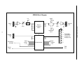
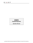
The ADVANTAGE PMX84 Programmable Matrix Switcher provides eight
inputs and four outputs under microprocessor control, with complete
programmability and remote control of crosspoint switching via infrared, wallmount panel, logic inputs, and/or computer. Multiple units may be used to
expand input/output capability of the matrix. The PMX84 is extremely versatile,
and ideal for applications such as room combining, zone paging, program
routing, and mix-minus. The PMX84 carries a Five-Year ‘Gold Seal’ Warranty.
PMX84 features include:
♦ eight balanced line inputs with level control & peak indicator
♦ four balanced line outputs with level, patch, & expansion
♦ inputs and outputs provided on plug-in barrier strip terminals
Block Diagram
pg. 22
♦ linking of multiple units for increased matrix inputs/outputs
Specifications
pg. 23
♦ all inputs are assignable to all outputs in any configuration
Warranty
♦ input/output assignments via ‘on’, ‘off’, or ‘toggle’ switching
♦ up to fifty presets affecting single or multiple inputs/outputs
♦ four remote control ports with location assignable commands
♦ remote control via infrared, wall-panels, switches, or RS-232
♦ sixteen logic inputs for remote control via external switches
♦ logic inputs include combining, override, & default modes
♦ sixteen logic outputs for controlling external circuits or relays
♦ logic output assignments via ‘on’, ‘off’, or ‘toggle’ switching
♦ serial port for programming and/or RS-232 computer control
♦ linking port for combined remote control of multiple units
♦ front panel indicators display input-to-output assignments
®
♦ PC control software for Windows 95 & serial cable included
♦ incorporates AES recommended grounding practices
♦
marked and UL / C-UL listed power source
♦ covered by Five-Year ‘Gold Seal’ Warranty
?
After reading this manual, if you have any questions or need technical
assistance, please call Biamp Systems toll-free 1-800-826-1457.
☎
1
FRONT & REAR PANEL FEATURES
1
output A
output B
output C
output D
input channels
2 3 4 5 6 7
input channels
2 3 4 5 6 7
input channels
2 3 4 5 6 7
input channels
2 3 4 5 6 7
8
1
8
1
8
1
ADVANTAGE PMX84
Programmable Matrix Switcher
8
error
remote
power
o
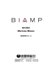
FRONT PANEL FEATURES
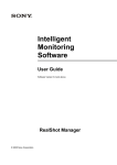
REAR PANEL FEATURES
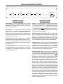
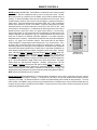
Output Displays: These four LED displays show the various
input/output assignments of the matrix switcher. Each group of
eight indicators will display which Inputs (1~8) are currently
assigned to that Output (A~D).
Inputs 1~8: These plug-in barrier strips provide the balanced linelevel inputs to the matrix switcher. For balanced input, wire high to
(+), low to (-), and ground to ( ). For unbalanced input, wire high
to (+) and ground to both (-) & ( ). When using multiple PMX84s
to expand the matrix output capability, wire each source (in
parallel) to the respective input on each PMX84. From the factory,
all Inputs are assigned to all Outputs.
ý
ý
Error Indicator: This indicator will flash when unusable
information has been received via remote control (see Remote
Controls on pg. 4). If an error in transmission/reception of a
command occurs, the Error indicator will flash. The Error Indicator
will also flash continuously whenever an emergency override is
activated (see Override on pg. 3).
Input Trim Controls & +10 Indicators: The Trim controls adjust
gain at the associated inputs to compensate for different signal
levels. For best performance, set Trim so the +10 indicator is
activated only by occasional peaks in signal level. When the +10
indicator lights, 8dB of headroom remains before clipping. When
Trim is centered, input to balanced output level will be unity gain.
Remote Indicator: This indicator will flash when any information
is received via remote control (see Remote Controls on pg. 4). If
the Remote and Error indicators flash simultaneously, this may be
an indication of improper installation. Check location and wiring of
all remote controls.
Outputs A~D: These plug-in barrier strips provide the balanced
line-level outputs from the matrix switcher. For balanced output,
wire high to (+), low to (-), and ground to ( ). For unbalanced
output, wire high to (+) and ground to ( ), leaving (-) unconnected.
Signal level will be reduced by 6dB when outputs are unbalanced.
From the factory, all Inputs are assigned to all Outputs.
ý
Power Switch & Indicator: When the Power Switch is turned on,
the adjacent indicator will light. When power is turned off, all
current settings will be stored in non-volatile memory and recalled
when power is turned back on.
ý
Patch & Expansion Input: These 3-conductor 1/4” phone jacks
allow insertion of external signal processing at the Outputs, as well
as inter-connection of multiple PMX84s to expand the matrix input
capability. Patch jacks are wired with Tip as send, Ring as return,
and Sleeve as a common ground. They may be used to provide
both input and output for external signal processing devices, such
as remote controls & equalizers. Expansion Input jacks are wired
with Tip as input, Ring as output, and Sleeve as a common
ground. They are used in conjunction with the Patch jacks on
other PMX84s, to increase the number of inputs assignable to the
matrix. For this purpose, Expansion Input jacks are connected to
Patch jacks using 3-conductor 1/4” phone cables (Biamp #9090013-00). To combine the inputs of two PMX84s, connect the
Patch jacks of the first unit to the Expansion Input jacks of the
second unit. Both units will provide identical matrix output signals,
with all sixteen inputs being assignable. Additional PMX84s may
be connected in this same fashion, to further increase the matrix
input capacity. External signal processing may still be inserted at
the Outputs, by utilizing the Patch jacks available on the ‘last’
PMX84 in the chain. Signal processing inserted here will affect the
Outputs of all PMX84s in the chain.
2
FRONT & REAR PANEL FEATURES
remote inputs
1
2
3
inputs
outputs
BIAMP SYSTEMS
Portland, Oregon
4
B
an affiliate of Rauland-Borg Corp. MADE IN U.S.A.
A
level
IR2
IR3
IR2
IR3
gnd
IR2
IR3
gnd
IR2
IR3
gnd
gnd
patch
logic outputs
level
expansion
input
~27V 15VA
50/60 Hz
Class 2 wiring
patch
patch
override
logic inputs
expansion
input
patch
expansion
input
+10
+10
6
level
+10
level
+10
7
level
1
level
+10
8
level
2
level
+10
C
level
3
level
expansion
input
D
serial port
4
5
level
+10
level
+10
PMX link
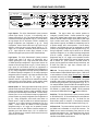
Logic Outputs: This 25-pin Subminiature-D (male) connector
provides Logic Outputs 1~16 (pins 1~16 respectively) and a
common ground (pins 17~25). Logic Outputs allow remote control
of external circuits (see Logic Outputs on pg. 8). From the factory,
all Logic Outputs are ‘off’ and access to them is available only
through Configuration (see Configuration on pg. 10). During
Configuration, remote control buttons and Logic Inputs may be
defined to control the various Logic Outputs, utilizing ‘on’, ‘off’,
‘toggle’, and ‘no operation’ commands (see Remote Controls on
pg. 4). Logic Outputs can control relays, indicators, or other
products having logic inputs (such as VSX41 Video Switchers).
Override: This plug-in barrier strip terminal provides an
‘emergency’ (override) function. Override operates like a Logic
Input, and is activated when shorted to the adjacent ground ( ).
However, Override maintains a higher priority than any other Logic
Input or remote control button. When Override is released (no
longer shorted to ground), the PMX84 will automatically revert to
its previous settings, and to normal operation. From the factory,
Override is non-functional and may be programmed to perform
functions only through Configuration (see Configuration on pg. 10).
During Configuration, Override may be defined as an individual
input/output assignment, or as multiple input/output assignments
(such as a preset). Override is defined to affect input/output
assignments using ‘on’, ‘off’, ‘toggle’, and ‘no operation’ functions.
The Override terminal performs the functions defined for button
#40 on Remote #4. When Override is activated (shorted to
ground), the front panel Error Indicator will flash continuously, and
all Serial Port, PMX Link, Logic Input, & Remote Input 1~4
commands will be ignored.
ý
Logic Inputs: This 25-pin Subminiature-D (female) connector
provides Logic Inputs 1~16 (pins 1~16 respectively) and a
common ground (pins 17~25). Logic Inputs allow remote control
of PMX84 input/output assignment & Logic Output functions via
external circuits (see Logic Inputs on pg. 6). From the factory, all
Logic Inputs are non-functional and may be programmed to
perform functions only through Configuration (see Configuration on
pg. 10). During Configuration, each Logic Input may be defined as
an individual input/output assignment, or as multiple input/output
assignments (such as a preset). Logic Inputs are defined to affect
input/output assignments using ‘on’, ‘off’, ‘toggle’, and ‘no
operation’ functions. Logic Inputs can be controlled via switches,
contact-closures, active driver circuits, or other products having
®
logic outputs (such as the ADVANTAGE AGII and DRC 4+4).
PMX Link: This plug-in barrier strip terminal provides a ‘linking’
interface between multiple PMX84s within a system. PMX Link is
a communications bus, which allows Remote Input & Logic Input
commands received by one PMX84 to be ‘shared’ by all PMX84s
in the system. However, the way that each PMX84 in the system
responds to these ‘shared’ commands can be completely different,
as defined during Configuration (see Configuration on pg. 10). To
‘link’ multiple PMX84s, connect the PMX Link and adjacent ground
( ) terminals from each PMX84 to the respective terminals on the
next PMX84, in a parallel fashion. NOTE: RS-232 commands
received at the PMX84 Serial Port are not included at PMX Link.
Remote Inputs 1~4: These plug-in barrier strips accept up to four
optional remote controls (see Remote Controls on pg. 4). Remote
controls may be infrared, wall-mount, and/or customized, and may
be wired up to 2000 feet away from the PMX84. From the factory,
Remote Inputs 1~4 are non-functional and may be programmed to
perform functions only through Configuration (see Configuration on
pg. 10). During Configuration, each remote control button on
Remote Inputs 1~4 may be defined as an individual input/output
assignment, or as multiple input/output assignments (such as a
preset). Control buttons are defined to affect input/output
assignments using ‘on’, ‘off’, ‘toggle’, and ‘no operation’ functions.
Each control button can have different functions assigned to it,
depending upon which Remote Input (1~4) it is received from.
This is an effective way to customize remote control functions for
specific zones or locations.
ý
Serial Port: This 9-pin Subminiature-D (male) connector provides
an RS-232 Serial Port. PC Control Software and a serial cable are
provided (see Configuration on pg. 10). The Serial Port also
allows remote control via computer, or via third-party controllers
which use the RS-232 protocol (see Computer Control on pg. 13).
AC Power Cord: The power transformer provides 27 Volts AC to
the PMX84, and is detachable via a 5-pin DIN connector. The
PMX84 has two internal ‘self-resetting’ fuses (there are no user
servicable parts inside the unit). If the internal fuses blow, they will
attempt to re-set after a short period. However, this may be an
indication that the PMX84 requires service.
3
REMOTE CONTROLS
The type and quantity of remote controls are optional for the PMX84. Remote controls affect the individual input/output assignments, as
well as selection of more global ‘preset’ assignments (see Configuration on pg. 10). Remote controls may be added at any time, and do
not require the PMX84 to be modified, opened, or removed from a rack. There are four types of remote controls available: The Infrared
Transmitter, the Infrared Receiver, the Wall-Mount Panel, and the Remote Interface Kit. The PMX84 may also be controlled via switches
(Logic Inputs), computer (RS-232), and various third-party controllers. NOTE: Remote controls come with complete instructions.
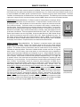
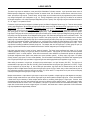
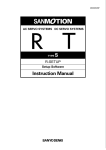
Infrared Receiver (Biamp #909-0030-00): The Receiver consists of a black plastic box, containing an infrared
photo detector, an LED indicator, and five screw terminals. To install the Receiver, first take off the front cover
by removing four screws. Mount the Receiver to a wall or other surface, using the two screw holes on the back
cover (screws not included). The Receiver should not be mounted in direct sunlight, or pointed directly at
fluorescent lighting. Receiver performance may be adversely affected by electronic ballasts. For best results,
there should be an unobstructed line-of-sight from Transmitter to Receiver. The Receiver may be wired up to
2000 feet from the PMX84, using 2-conductor shielded cable (not included). Route cable through access hole
on the bottom of the Receiver. Three screw terminals inside the Receiver ("GND", "IR2", & "IR3") correspond to
"Remote Input" terminals on the rear of the PMX84. Connect the cable shield to the "GND" terminals at each
end. Use the two conductors to connect "IR2" to "IR2" & "IR3" to "IR3". Replace the Receiver front cover. The
LED indicator inside the Receiver lights when infrared information is detected. NOTE: The Infrared Receiver
also includes two 'Remote Translator' terminals ("GND" & "XLATE"), which allow remote control of the PMX84
via third-party 'serial' controllers. Complete instructions are included with the Infrared Receiver.
InfraRed Transmitter (Biamp #909-0065-00): The Transmitter is a hand-held controller, which transmits
infrared codes unique to Biamp. Therefore, the Transmitter should not affect any other infrared controlled
equipment (such as TVs or VCRs). Likewise, other infrared controllers will not provide proper control of Biamp
equipment. The Transmitter requires two AAA batteries, which are included with the unit (user installed). The
Transmitter has twenty-eight buttons. Each button is labelled with both a number and a letter, as a generic
button reference. From the factory, remote control buttons are non-functional and may be programmed to
perform functions only through Configuration (see Configuration on pg. 10). During Configuration, each remote
control button may be defined as an individual input/output assignment, or as multiple input/output assignments
(such as a preset). Control buttons are defined to affect input/output assignments using ‘on’, ‘off’, ‘toggle’, and
‘no operation’ functions. Each control button can have different functions assigned to it, depending upon which
Remote Input (1~4) it is received from. This is an effective way to customize remote control functions for specific
zones or locations. By downloading a specific file (‘startup.pmx’) during Configuration, the PMX84 may be
programmed so that each button assigns a specific input to a specific output. Under these circumstances, the
button labelling indicates which input (number) is assigned to which output (letter). (Example: button ‘1 A’
assigns Input 1 to Output A; button ‘2 B’ assigns Input 2 to Output B; button ‘3 C’ assigns Input 3 to Output C;
button ‘4 D’ assigns Input 4 to Output D; etc.). This file does not allow Input 8 to be assigned via the Transmitter.
It is reserved as an ‘emergency/all-call’ input, which can be assigned to Outputs A~D using the Override terminal
(see Rear Panel Features on pg. 3). This file also designates a ‘toggle’ function for the remote control buttons.
This ‘toggle’ function works as a ‘push-on/push-off’ assignment. (Example: pressing button ‘7 A’ once assigns
Input 7 to Output A; pressing button ‘7 A’ again un-assigns Input 7 from Output A; etc.). For best results, there
should be an unobstructed line-of-sight from Transmitter to receiver. The Transmitter will operate up to 30 feet
from a receiver. In addition to the Infrared Receiver described above, receivers are also included on the PMX84
and the Wall-Mount panel (see next page). NOTE: Default button definitions are all ‘no operation’.
4
InfraRed Receiver
External Receiver
(Biamp #909-0030-00)
1A
1B
1C
1D
2A
2B
2C
2D
3A
3B
3C
3D
4A
4B
4C
4D
5A
5B
5C
5D
6A
6B
6C
6D
7A
7B
7C
7D
ADVANTAGE PMX84
Infrared Transmitter
(Biamp #909-0065-00)
REMOTE CONTROLS
Wall-Mount (Biamp #909-0075-00): The Wall-Mount is a "hard-wired" control, which is powered
by the PMX84. There are no batteries to wear out, and it is not easily lost or stolen. The WallMount may be wired up to 2000 feet from the PMX84, using 2-conductor shielded cable (not
included). To install the Wall-Mount, first remove the mounting box from the front panel. Route
the cable through a "knock-out" hole on the rear of the mounting box. Install the mounting box in
a wall or panel. Three screw terminals on the circuit board ("GND", "IR2", & "IR3") correspond to
"Remote Input" terminals on the rear of the PMX84. Connect the cable shield to the "GND"
terminals at each end. Use the two conductors to connect "IR2" to "IR2" & "IR3" to "IR3". Install
the front panel on the mounting box. The Wall-Mount has twenty-eight buttons. Each button is
labelled with both a number and a letter, as a generic button reference. From the factory,
remote control buttons are non-functional and may be programmed to perform functions only
through Configuration (see Configuration on pg. 10). During Configuration, each remote control
button may be defined as an individual input/output assignment, or as multiple input/output
assignments (such as a preset). Control buttons are defined to affect input/output assignments
using ‘on’, ‘off’, ‘toggle’, and ‘no operation’ functions. Each control button can have different
functions assigned to it, depending upon which Remote Input (1~4) it is received from. This is
an effective way to customize remote control functions for specific zones or locations. By
downloading a specific file (‘startup.pmx’) during Configuration, the PMX84 may be programmed
so that each button assigns a specific input to a specific output. Under these circumstances, the
button labelling indicates which input (number) is assigned to which output (letter). (Example:
button ‘1 A’ assigns Input 1 to Output A; button ‘2 B’ assigns Input 2 to Output B; button ‘3 C’
assigns Input 3 to Output C; button ‘4 D’ assigns Input 4 to Output D; etc.). This file does not
allow Input 8 to be assigned via the Transmitter. It is reserved as an ‘emergency/all-call’ input,
which can be assigned to Outputs A~D using the Override terminal (see Rear Panel Features on
pg. 3). This file also designates a ‘toggle’ function for the remote control buttons. This ‘toggle’
function works as a ‘push-on/push-off’ assignment. (Example: pressing button ‘7 A’ once
assigns Input 7 to Output A; pressing button ‘7 A’ again un-assigns Input 7 from Output A; etc.).
The red LED will flash whenever the Wall-Mount is transmitting information. The Wall-Mount
includes an infrared detector, which allows it to operate as an Infrared Receiver, as well. The
infrared detector may be disabled via an internal circuit board jumper strap (labelled "IR RECV").
NOTE: Defualt button definitions are all ‘no operation’.
1A
1B
1C
1D
2A
2B
2C
2D
3A
3B
3C
3D
4A
4B
4C
4D
5A
5B
5C
5D
6A
6B
6C
6D
7A
7B
7C
7D
ADVANTAGE PMX84
Wall-Mount Panel
(Biamp #909-0075-00)
Remote Interface Kit (Biamp #909-0041-00): The Remote Interface Kit allows the user to create a customized control panel, using his
own momentary switches, enclosure, and panel. It can provide up to 40 buttons (12 more than standard remote controls), which are
supported by the PMX84. The Remote Interface Kit is a tested circuit board assembly, which includes two wiring harnesses. The circuit
board connects to the PMX84 in exactly the same way the Infrared Receiver or Wall-Mount does, using 2-conductor shielded cable (not
included), and may be wired up to 2000 feet from the PMX84. The circuit board is 2.27"W by 2.65"H, with four mounting holes (2" centers)
and #6 mounting hardware provided.
5
LOGIC INPUTS
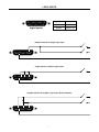
The sixteen Logic Inputs are available on a rear panel 25-pin Subminiature D (female) connector. Logic Inputs allow remote control of
PMX84 input/output assignment & Logic Output functions via external circuits, such as switches, contact-closures, active driver circuits,
and/or ‘open-collector’ logic outputs. From the factory, all Logic Inputs are non-functional and may be programmed to perform functions
only through Configuration (see Configuration on pg. 10). During Configuration, each Logic Input may be defined as an individual
input/output assignment, or as multiple input/output assignments (such as a preset). Each Logic Input may also be defined with either an
‘on’, ‘off’, ‘toggle’, or ‘no operation’ function.
Furthermore, Logic Inputs may be assigned in ‘prioritized’ groups (see Global Configuration Screen on pg. 12). There are seven possible
‘priority’ group assignments: A) No Priority (all Logic Inputs at same priority level); B) One Group of Four (Logic Inputs 1~4); C) Two
Groups of Four (Logic Inputs 1~4 & 5~8); D) Three Groups of Four (Logic Inputs 1~4, 5~8, & 9~12); E) Four Groups of Four (Logic
Inputs 1~4, 5~8, 9~12, & 13~16); F) One Group of Eight (Logic Inputs 1~8); G) Two Groups of Eight (Logic Inputs 1~8 & 9~16). Within
each priority group, the lower numbered Logic Input has highest priority. Logic Inputs are affected by priority only within these groups.
Logic Inputs in one group will not have priority over Logic Inputs in another group. Likewise, Logic Inputs assigned to priority groups do not
have priority over Logic Inputs which are not assigned to priority groups. Also, within each priority group there is a ‘fall-back’ function. This
‘fall-back’ function allows a higher priority Logic Input to override a lower priority Logic Input, and then automatically revert to the lower
priority Logic Input when the higher priority Logic Input is released (assuming the lower priority Logic Input is still being activated). Since
Logic Inputs are controlled by switches, contact-closures, etc., each Logic Input is allowed two button definitions (one for switch ‘closed’
and one for switch ‘open’). Therefore, button definitions are also available for when certain groups of Logic Inputs are all ‘open’. This is
very effective for creating an additional ‘fall-back’ priority level. For example, when all of the Logic Input 1~4 priority group are ‘open’ (no
paging), a special button definition may be activated which selects a ‘fall-back’ assignment (such as background music).
Logic Inputs may also be set for ‘normal’ or ‘binary’ modes of operation. The ‘binary’ mode reconfigures Logic Inputs 9~12 for ‘room
combining’ applications, utilizing one Logic Input (switch) for each room partition. This supports up to four rooms, with sixteen possible
combinations of ‘open’ or ‘closed’ partitions. Under these circumstances, button definitions are created which perform the appropriate
input/output assignments when specific room partitions are moved (switches ‘opened’). In Binary mode, Logic Inputs 1~8 operate
normally, however, Logic Inputs 13~16 are unused (disabled). Files are available for downloading to the PMX84, which represent typical
uses of Logic Input Priority & Logic Input Mode, for page routing & room combining applications (see Application on pgs. 16~21).
When nothing is connected to a Logic Input, an internal pull-up resistor keeps it at a ‘high’ idle state (+5.0 VDC). The Logic Input is
activated when its input goes ‘low’ (less than +0.8 VDC), and is de-activated when its input goes ‘high’ (greater than +2.4 VDC). A Logic
Input is controlled in one of three ways: 1) Use an NPN style ‘open-collector’ logic output from an external device (such as an AGII
Autogate or DRC 4+4 Digital Remote Control) to short the Logic Input to ground. 2) Use a switch, relay, or other contact-closure (such as
from a third-party controller) to short the Logic Input to ground. 3) Use an active TTL output driver circuit (such as from a third-party
controller) to actively drive the Logic Input to a ‘high’ or ‘low’ state.
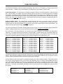
Multiple contact-closures or ‘open-collector’ logic outputs or may be wired in parallel to a single Logic Input (see diagrams on next page).
Likewise, a single contact-closure or ‘open-collector’ logic output may be wired in parallel to multiple Logic Inputs. In some circumstances,
a diode matrix may be necessary to isolate multiple switches which are controlling similar groups of Logic Inputs. However, these
circumstances may be rare, since each individual Logic Input may be defined to perform multiple funtions. Logic Outputs and contactclosures should be rated for at least 5 Volts / 1mA operation. Low-current / dry-contact closures are recommended for reliability. Active
output driver circuits should not exceed a signal range of 0~5 Volts DC, and should have a minimum pulse width of 100 milli-seconds.
Logic Input impedances are approximately 10k ohms.
6
LOGIC INPUTS
13
1
25
14
logic inputs
logic inputs
pin numbers
logic #1~16
pin #1~16
ground
pin #17~25
multiple switches to single Logic Input
13
25
1
14
single switch to multiple Logic Inputs
13
25
1
14
multiple switches to multiple Logic Inputs (diode isolation)
13
25
1
14
7
LOGIC OUTPUTS
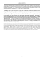
The sixteen Logic Outputs are available on a rear panel 25-pin Subminiature D (male) connector. Logic Outputs provide remote control of
external circuits, such as relays and/or indicators. From the factory, all Logic Outputs are ‘off’ and access to them is available only through
Configuration (see Configuration on pg. 10). During Configuration, remote control buttons and Logic Inputs may be defined to control
switching of the various Logic Outputs, utilizing ‘on’, ‘off’, ‘toggle’, and/or ‘no operation’ commands.
The PMX84 logic outputs are ‘open collector’ outputs. Each logic output is an NPN transistor with the collector being the output and the
emitter being ground (see diagram on next page). When a logic output is turned on, the transistor provides a path for DC current to flow.
The logic outputs do not provide any voltage or current. They act only as switches (with a common ground return). To activate external
relays, an external power supply must be used (see diagram on next page). The logic output transistors are rated up to a maximum of 24
VDC and 50 mA per output (24 volt relay coils maximum). However, +12 Volts DC is sufficient power for most applications. When using
the logic outputs to control relays, protection diodes must be used to suppress high voltage transients that are generated when the relays
turn off (see diagram below). Any of the 1N4004 family of diodes (1N4001, 1N4002, 1N4003, 1N4004, 1N4005, 1N4006, 1N4007, or
equivalent) will provide proper protection. A 12 Volt Power Supply (#929-0011-00), 12 Volt DPDT Relays (#520-0064-00), and 1N4004
Diodes (#190-0003-09) are available from Biamp. When a logic output goes on, the associated relay may be wired to perform on, off, or
‘A/B’ switching functions. To use a logic ‘on’ command to turn on (or activate) a device, wire across the ‘normally open’ relay contacts, in
series with the device (or control voltage source). To use a logic ‘on’ command to turn off a device (or speaker), wire across the ‘normally
closed’ relay contacts, in series with the device (or control voltage source). To use a logic ‘on’ command to select between ‘A’ or ‘B’
signals (inputs or outputs), wire one to the ‘normally closed’ relay terminal and the other to the ‘normally open’ relay terminal, with the
common relay terminal providing the feed (input or output).
Likewise, Logic Outputs may be used in conjunction with an external power supply, for controlling external indicators such as LEDs (see
diagram on next page). When a Logic Output goes on, the circuit for the external indicator is completed (Logic Output provides path for
DC current to flow). Again, a +12 Volts DC power supply is appropriate. Typically, an LED will require about 8 mA of current to achieve
sufficient brightness. Therefore, the value of ‘R’ should be 1.2k ohms. If the LED used requires more current to achieve sufficient
brightness, the value of ‘R’ may be reduced to a minimum of 1k ohm. This would provide 10 mA of current to the LED. Remote control
buttons and Logic Inputs can be defined to control matrix input/output assignments and/or Logic Output switching. Therefore, external LED
circuits may be used to indicate virtually anything, including PMX84 matrix input/output assignments or status of external systems.
8
LOGIC OUTPUTS
1
13
14
25
logic outputs
pin numbers
logic #1~16
pin #1~16
ground
pin #17~25
logic outputs
PMX84
Pin #1
+12 Volts DC
Power Supply
−
+
12V Relay
Contacts
normally closed
common
normally open
Logic Output #1
1N4004
Diode
Coil
Pin #25
PMX84
Pin #1
+12 Volts DC
Power Supply
−
+
Indicator Panel
R
Logic Output #1
LED
Pin #25
9
CONFIGURATION
®
All Configuration parameters are adjustable using the Windows 95 'PC Control Software' and serial cable provided with the PMX84. The
®
PC Control Software provides programs for various ADVANTAGE products, including the PMX84. The PMX84 program includes multiple
control screens, which are described on the following pages. Factory default settings are shown on each screen. Once the software is
started (and Comm Port Configuration is set), various screens are accessible through the drop-down menus at the top of the opening
screen. The Mix screen appears whenever a PMX84 file is opened. Additional control screens are then available from the Configure
PMX84 menu. The File menu provides functions such as open, close, save, etc. Pre-programmed files are provided with the PC Control
Software, which can be downloaded to the PMX84 for typical applications, such as page routing & room combining. The Settings menu
recalls the Comm Port Configuration screen. The Window menu arranges the active product screens. The Help menu explains the
®
®
available adjustments. To install the Windows 95 PC Control Software: Select ‘Run” from the Windows 95 ‘Start’ menu, then type
®
A:\SETUP and click ‘OK’. System Requirements: Windows 95 with 8MB RAM & 2MB available hard disk space A serial port is required
for actual ‘on-line’ operation and control of a PMX84).
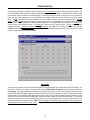
MIX SCREEN
The Mix screen allows direct control of the individual Matrix Switch (input/output) Assignments and the Logic Outputs of the PMX84. The
Mix screen is divided into two sections. The upper section affects the Matrix Switch Assignments and the lower section affects the
Logic Outputs. Left-clicking a Matrix Switch Assignment or a Logic Output will ‘toggle’ it on or off. Right-clicking will instead open a popup menu, which allows Matrix Switch Assignments & Logic Outputs to be turned on & off individually or in groups. The Mix screen provides
a graphic display of all current Matrix Switch Assignments and Logic Outputs, as well as allowing real-time control of the PMX84. The title
bar at the top of the Mix screen shows Device Number, custom Device Name, & Model of the product being controlled. The PC Control
Software can operate ‘off-line’ (no product connected) by opening a ‘new’ file for the desired product. The Device Number for ‘off-line’ files
is assigned sequentially as a negative number. NOTE: Files are available for downloading during Configuration, which are designed for
specific applications (see Applications on pgs. 16~21).
10
CONFIGURATION
BUTTON DEFINITION SCREENS
Button Definition screens are used to assign specific ‘actions’ to remote control buttons (and logic inputs). Button Definition screens are
accessed through the Configure PMX84 drop-down menu. There are five Button Definition screen tabs to choose from (Remote 1~4 &
Logic Inputs). Button Definition screens are divided into two sections. The right section indicates which Remote Control Button is
currently selected. The lower set of twenty-eight buttons represents the buttons found on a standard remote control (see Remote Controls
on pg. 4). The PMX84 also supports the 12 buttons shown above, which are accessible via Remote Interface Kit or Computer control.
Left-clicking a button selects it to be defined. The left section of the screen shows the Matrix Switch & Logic Output Actions assigned to
the selected button. Left-clicking a Matrix Switch or Logic Output cycles through the four actions available actions (no operation, turn off,
turn on, & toggle). Right-clicking instead opens a pop-up menu, allowing Matrix Switch & Logic Output Actions to be assigned individually
or in groups. A button can be assigned multiple actions, affecting any number of Matrix Switches & Logic Outputs, much like a preset.
Button Definition not only allows a particular button to be defined, but also from which Remote Input (1~4) that button command is
received. This allows a button to perform different actions, depending upon which location it comes from. The sixteen Logic Inputs (and
the Override terminal) are also available for button definition. Logic Inputs are activated by switches. Therefore, each Logic Input is
allowed two button definitions (one for switch ‘closed’ and one for switch ‘open’). Button definitions are also available for when certain
groups of Logic Inputs are all ‘open’. The Logic Inputs screen also includes a special definition which is triggered each time the PMX84 is
powered up. The Override terminal acts like a logic input, but performs the actions as defined for button #40 on Remote #4. The Override
terminal has the ability to temporarily store current settings, and recall them when Override is released (switch opened). This same
function is available for buttons & logic inputs, by selecting Store Temp Mix or Recall Temp Mix at the upper-left of the screen. These
actions are typically used for paging, where it is desired to return to previous settings after the page. (Example: Logic Input ‘closed’ stores
current settings and initiates page, then Logic Input ‘opened’ recalls previous settings.) When a button is selected, the Echo Character is
shown at the upper portion of the screen. Echo Characters may be used (via RS-232 computer control) to emulate the remote control
buttons. However, the Echo Character for a button may be changed via the drop-down menu, for customizing RS-232 system control.
Left-clicking Default / Clear opens a pop-up menu, allowing the selected button (or all buttons) to be reset to ‘no operation’. Once a button
definition is changed, left-clicking Store saves the new definition, or left-clicking Cancel reverts to the prior definition. Left-clicking Help
provides additional instruction. Once a button definition is stored, left-clicking Try It will actually perform those actions. Left-clicking Close
returns to the Mix screen. Fifty button definitions are available, and the number of remaining definitions is shown at the upper-right of the
screen. NOTE: Default button definitions are all ‘no operation’.
11
CONFIGURATION
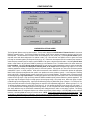
CONFIGURATION OPTIONS SCREEN
The Configuration Options screen has three sections. The top section displays the Serial Number & Firmware Version for the current
PMX84 (if operating ‘on-line’). The PC Control Software can operate ‘off-line’ (with no product connected) by opening a ‘new’ file for the
desired product. The Serial Number & Firmware Version are not displayed for ‘new’ (off-line) files. Left-clicking Device Number opens a
drop-down menu which allows assignment of an ‘address’ number (1~8). When more than one PMX84 is used in a system, their serial
ports may be connected together (see Computer Control on pg. 14). Under these circumstances, RS-232 commands (from computer or
certain third-party controllers) may be routed to specific PMX84s in the system, using their Device Numbers. Left-clicking Device Name
allows a custom name to be given to the PMX84, by entering up to 30 characters of text. The middle section of the screen selects the
Logic Input Mode. Left-clicking all logic inputs normal allows all Logic Inputs to operate independently, except for priority as described
below. Left-clicking 1-8 normal, 9-12 binary/room combining mode, 13-16 unused instead reconfigures Logic Inputs 9~12 for ‘room
combining’ applications, utilizing one Logic Input (switch) for each room partition. This supports up to four rooms, with sixteen possible
combinations of ‘open’ or ‘closed’ partitions. Under these circumstances, button definitions are created which perform the appropriate
Matrix Switch (input/output) assignments when specific room partitions are moved (switches ‘opened’). In the binary/room combining
mode, Logic Inputs 1~8 operate normally, however, Logic Inputs 13~16 are unused (disabled). The bottom section of the screen selects
the desired grouping of Logic Input Priorities. Left-clicking the adjacent arrow button opens a drop-down menu of seven different priority
schemes for the Logic Inputs. Logic Input Priority allows the PMX84 to establish a priority scheme suitable to a particular application. The
Logic Inputs may be assigned in single or multiple groups, with each group having 4 or 8 priority levels. Within each group, the lower
numbered Logic Input has highest priority. Logic Inputs are affected by priority only within these groups. (Example: ‘Four Groups of Four
Priority’ would work well when four levels of paging priority are required in four independent paging zones. Where Logic Inputs 1, 5, 9, &
13 represent the highest ‘emergency’ priority level, Logic Inputs 2, 6, 10, & 14 represent the second ‘all-call’ priority level, Logic Inputs 3, 7,
11, & 15 represent the third ‘local page’ priority level, and Logic Inputs 4, 8, 12, & 16 represent the lowest ‘message repeater’ priority level.
Also, button definitions may be created which automatically select ‘background music’ when no zone paging is present. Left-clicking
Restore Defaults allows all Configuration Options to be restored to their factory default settings. Left-clicking Help provides additional
instruction. Left-clicking Close will return you to the Mix screen. NOTE: Factory default settings are shown on the screen above. Files
are available for downloading during Configuration, which are designed for specific applications (see Applications on pgs. 16~21). These
files represent typical uses of Logic Input Priority & Logic Input Mode, for paging routing & room combining applications.
12
COMPUTER CONTROL
®
The ADVANTAGE PMX84 has an RS-232 compatible serial interface, which allows it to be controlled by a computer (see Rear Panel
Features on page 3). In addition to the PC Control Software, the PMX84 offers two other methods of computer control.
Control Button Emulation: This method allows the computer to emulate the operation of the infrared transmitter or wall-mount control
panel. Using this method, the computer outputs ASCII characters, which are equivalent to the commands generated by the standard
control buttons. The PMX84 is unable to tell whether these commands come from the computer or from a standard control. However,
Control Button Emulation allows the computer to utilize up to forty button definitions (unlike standard controls, which have only twenty-eight
buttons). When using up to four PMX84s in a system, Control Button Emulation also allows the computer to designate which device or
devices should react to each control button command.
Advanced Computer Control: This method provides advanced commands, which allow the computer to retrieve or edit matrix
assignments, retrieve or edit control button definitions, and a variety of other functions. The computer may also emulate control buttons.
Using this method, the computer may designate up to eight devices, and may create unlimited presets and control button definitions. The
computer may also provide "real-time" display of input/output assignments.
This manual only describes the Control Button Emulation method of computer control. For complete details about using the PMX84 with a
computer, including Advanced Computer Control, contact Biamp Systems for manual "Computer Control of PMX84".
Each control button on the infrared transmitter or the wall-mount control panel corresponds to one character in the standard ASCII
character set. The character equivalents are summarized in the following table. This table includes all forty of the possible buttons, their
button numbers, their ASCII code equivalents, and their factory default button definitions. From the factory, remote control buttons are
non-functional and may be programmed to perform functions only through Configuration (see Configuration on pg. 10).
button 01
button 02
button 03
button 04
button 05
button 06
button 07
button 08
button 09
button 10
button 11
button 12
button 13
button 14
B
C
D
E
F
G
H
I
J
K
L
M
N
O
no definition assigned
no definition assigned
no definition assigned
no definition assigned
no definition assigned
no definition assigned
no definition assigned
no definition assigned
no definition assigned
no definition assigned
no definition assigned
no definition assigned
no definition assigned
no definition assigned
button 15 P no definition assigned
button 16 Q no definition assigned
button 17 R no definition assigned
button 18 S no definition assigned
button 19 T no definition assigned
button 20 U no definition assigned
button 21 V no definition assigned
button 22 W no definition assigned
button 23 X no definition assigned
button 24 Y no definition assigned
button 25 Z no definition assigned
button 26 [ no definition assigned
button 27 \ no definition assigned
button 28 ] no definition assigned
button 29
button 30
button 31
button 32
button 33
button 34
button 35
button 36
button 37
button 38
button 39
button 40
^
_
'
b
c
d
e
f
g
h
i
j
no definition assigned
no definition assigned
no definition assigned
no definition assigned
no definition assigned
no definition assigned
no definition assigned
no definition assigned
no definition assigned
no definition assigned
no definition assigned
no definition assigned
The computer can initiate any functions or actions that a standard control can, by simply transmitting the equivalent control button ASCII
character. When interfacing the PMX84 to a computer, the computer must be aware that the PMX84 will "echo" all characters it receives
(both from computer and standard controls) via the Serial Port 'transmit data' (TXD) signal.
Up to four PMX84s may be connected together, and addressed individually, when using Control Button Emulation. When multiple units are
used, each unit should be assigned a unique "Device Number" (see Configuration on pg. 10). Normally, all of the PMX84s would react to
control button commands. However, the computer can send commands to specific units, by preceding each command with a "device
select prefix" character (see following table). Only those PMX84s whose Device Numbers are specified will respond to the command
which follows. If a command is not immediately preceded by a device select prefix character, then all PMX84s in the system will react to
that command.
Select Device 1
Select Device 2
Select Devices 1 & 2
Select Device 3
Select Devices 1 & 3
l
m
n
o
p
Select Devices 2 & 3
Select Devices 1 & 2 & 3
Select Device 4
Select Devices 1 & 4
Select Devices 2 & 4
13
q
r
s
t
u
Select Devices 1 & 2 & 4
Select Devices 3 & 4
Select Devices 1 & 3 & 4
Select Devices 2 & 3 & 4
Select Devices 1 & 2 & 3 & 4
v
w
x
y
z
COMPUTER CONTROL
Serial Interface Electrical Connections & Cabling: The 9-pin Subminiature D (male) connector on the PMX84 rear panel provides the
RS-232 compatible serial interface signals used for computer control. The PMX84 transmits serial data on pin 3 (TxD) and receives serial
data on pin 2 (RxD). The serial interface ground is on Pin 5. The DTR & RTS signals are connected to the +12 Volt power supply (each
through its own resistor) and are always asserted when the PMX84 power is on. Most IBM compatible PCs use either 25-pin or 9-pin
(male) connectors for their serial ports. The following table summarizes the pin assignments for the PMX84 serial interface, and for the
standard IBM compatible 9-pin and 25-pin serial ports.
SIGNAL NAME
CD (carrier detect)
RxD (receive data)
TxD (transmit data)
DTR (data terminal ready)
signal ground
DSR (data set ready)
RTS (request to send)
CTS (clear to send)
RI (ring indicator)
DIRECTION
input
input
output
output
n/a
input
output
input
input
PMX84 9-PIN
n/a
pin 2
pin 3
pin 4
pin 5
n/a
pin 7
n/a
n/a
IBM-PC 9-PIN
pin 1
pin 2
pin 3
pin 4
pin 5
pin 6
pin 7
pin 8
pin 9
IBM-PC 25-PIN
pin 8
pin 3
pin 2
pin 20
pin 7
pin 6
pin 4
pin 5
pin 22
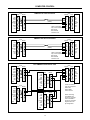
The PMX84 only requires receive data (pin 2), transmit data (pin 3), and signal ground (pin 5) to be connected for successful data
communications. However, the PC may require that signals be present on the data set ready, clear to send, or carrier detect inputs, as
well as the receive data, transmit data, and signal ground pins. The diagrams on the following page show cables for interfacing to a PC
with either a 9-pin or a 25-pin serial port connector. In most cases, one or the other of these cables will work. However, success or failure
depends entirely on the actual computer hardware and software being used. When trying to solve an interfacing problem, the most
important thing to remember is that an output of one device should connect to one or more inputs of the other device, and that two outputs
should never be connected together. Also, keep in mind that the RS-232 specification calls for the cable length to be no greater than 50
feet (although it is not unusual to be able to operate over distances of 150 to 250 feet), and the connectors must be of the appropriate
gender (male or female) to mate properly. For best results, a shielded cable should be used, with the shield connected to signal ground.
Since the PMX84 serial interface ground is also tied (indirectly) to the analog signal ground, undesirable ground loops may occur when the
PMX84 is connected to a PC (if the system grounding is not carefully designed). For best performance, the PC ground and the chassis
ground of the PMX84 should be at the same potential, and the PC should get AC power from the same source as the PMX84 (and any
other audio equipment which is connected to the PMX84).
Serial Interface Data Communications Parameters: The PMX84 communicates through the serial interface at a rate of 9600 bits per
second, with 8 data bits, 1 stop bit, and no parity. The PMX84 utilizes a subset of the standard 7-bit ASCII character set. The eighth data
bit of each character (the most significant bit) should always be 0. The computer should not echo the characters it receives. The computer
should not be set for either hardware (DTR) or software (XON/XOFF) flow control. The baud rate may be changed to 2400 bits per second
by means an internal jumper strap (J31). Jumper strap J31 is located on the right front corner of the lower circuit board, directly in front of
the microprocessor (U36). To select 2400 baud rate: 1) Disconnect power from the PMX84. 2) Remove top panel. 3) Using needlenose pliers, lift jumper strap J31 and move it over one pin (to the left). 4) Replace top panel & turn power on.
14
COMPUTER CONTROL
PMX84 to PC 9-Pin Connector
9-pin
PMX84
n/a
RxD
TxD
DTR
ground
n/a
RTS
n/a
n/a
male
female
1
2
3
4
5
6
7
8
9
1
2
3
4
5
6
7
8
9
n/a
RxD
TxD
DTR
ground
n/a
RTS
n/a
n/a
male
female
1
2
3
4
5
6
7
8
9
1
2
3
4
5
6
7
8
9
n/a
RxD
TxD
DTR
ground
n/a
RTS
n/a
n/a
male
1
2
3
4
5
6
7
8
9
1
2
3
4
5
6
7
8
9
9-pin
n/a
RxD
TxD
DTR
ground
n/a
RTS
n/a
n/a
#3
male
1
2
3
4
5
6
7
8
9
These connections
may not be required:
DTR to CD;
DTR to DSR;
or RTS to CTS.
female
#4
PMX84
(shield)
Four PMX84s Connected to a PC
9-pin
PMX84
These connections
may not be required:
DTR to CD;
DTR to DSR;
or RTS to CTS.
PMX84 to PC 25-Pin Connector
9-pin
PMX84
(shield)
female
1
2
3
4
5
6
7
8
9
9-pin
PMX84
n/a
RxD
TxD
DTR
ground
n/a
RTS
n/a
n/a
male
female
1
2
3
4
5
6
7
8
9
1
2
3
4
5
6
7
8
9
#1
9-pin
PMX84
n/a
RxD
TxD
DTR
ground
n/a
RTS
n/a
n/a
male
1
2
3
4
5
6
7
8
9
#2
15
9-pin
female
male
1
2
3
4
5
6
7
8
9
1
2
3
4
5
6
7
8
9
25-pin
female
male
8
3
2
20
7
6
4
5
22
8
3
2
20
7
6
4
5
22
9-pin
female
male
1
2
3
4
5
6
7
8
9
1
2
3
4
5
6
7
8
9
PC
CD
RxD
TxD
DTR
ground
DSR
RTS
CTS
RI
PC
CD
RxD
TxD
DTR
ground
DSR
RTS
CTS
RI
PC
CD
RxD
TxD
DTR
ground
DSR
RTS
CTS
RI
These connections
may not be required:
DTR to CD;
DTR to DSR;
or RTS to CTS.
female
1
2
3
4
5
6
7
8
9
When connecting
four PMX84s to a
PC 25-pin connector,
refer to "PMX84 to
PC 25-pin connector"
diagram above for
pin assignments.
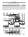
APPLICATIONS
Zone Paging with Background Music
Programming of the PMX84 for this application can be done simply by opening & downloading a file (page1a.pmx) during Configuration.
This application shows (1) master & (4) zone paging microphones connected to an Advantage EX module. The EX module provides the
mic preamplification necessary before entering the PMX84 (line-level signals do not require preamplification). Unbalanced line-level
signals from the EX Patch jacks (Channels 1~5) are then connected to Inputs 1~5 of the PMX84, respectively. A background music source
is connected to Input 6 of the PMX84. Outputs A~D of the PMX84 are connected to inputs of Advantage D60EQs for Zones 1~4,
respectively. The D60EQs provide amplification, equalization, & transformer output necessary for the distributed speakers in each zone.
Routing switches at each of the paging stations are wired to the appropriate Logic Inputs on the PMX84 (see diagram at bottom of page).
The Logic Inputs are programmed to perform the input/output assignments associated with their corresponding routing switches. The
Logic Inputs are also programmed in ‘four groups of four priority’. This allows each of the (4) zones to have its own (4) levels of priority.
The first level of priority in each zone is ‘all-call’ paging from the master paging station. The second level of priority in each zone is ‘zone’
paging from the master paging station. The third level of priority in each zone is ‘local’ paging from the respective zone paging station.
The fourth level of priority in each zone is ‘background music’, which can be turned on or off at the respective zone paging station.
Zone 3
paging
station
Zone 2
paging
station
E17934
DC out main out main stack main
patch
EX
from
paging
station
switches
pad
pad
in
patch
±12VDC 15W
Class 2
2
3
pad
in
patch
8
remote inputs
1
Zone 1
paging
station
5
logic outputs
IR2
IR3
IR2
IR3
gnd
IR2
IR3
gnd
IR2
IR3
gnd
gnd
4
A
patch
expansion
input
+10
8
+10
7
level
+10
1
level
level
+10
C
level
patch
1
2
level
+10
D
expansion
input
in
patch
2
3
level
expansion
input
level
patch
logic inputs
pad
in
patch
3
4
level
expansion
input
~27V 15VA
50/60 Hz
Class 2 wiring
override
pad
in
patch
background
music
inputs
B
level
serial port
pad
in
patch
outputs
Portland, Oregon
an affiliate of Rauland-Borg Corp. MADE IN U.S.A.
patch
PMX84
pad
in
patch
6
BIAMP SYSTEMS
4
pad
in
patch
7
master
paging
station
6
level
5
level
+10
+10
level
+10
PMX link
D60EQ
(Zone 3)
ADVANTAGE D60EQ
MADE IN U.S.A.
common
+ input
4Ω
- input
autoformer
input
gnd
115V: 2A SB fuse
230V: 1A SB fuse
ADVANTAGE D60EQ
115V
8Ω
115/230 VAC
F
SE
+ input
4Ω
- input
gnd
* FUS
ADVANTAGE D60EQ
115V
8Ω
115/230 VAC
* FUS
100V
SE
F
SE
- input
gnd
8Ω
100V
50/60 Hz 160 Watts
1 2 3 4
Zone 1
5 6 7 8
Zone 2
16
9 10 11 12
Zone 3
sic
mu
ge
Zone 4
pa
sic
mu
ge
Zone 3
pa
mu
ge
sic
Zone 2
pa
sic
mu
ge
pa
e4
ne
Zo
Zo
n
3
Zone 1
2
ne
1
Zo
ne
+ input
4Ω
70V
E * F
SE *
Zo
common
autoformer
input
115V: 2A SB fuse
230V: 1A SB fuse
U
SE *
all
MADE IN U.S.A.
U
* FUS
70V
F
common
E * F
Master
l-C
SE *
50/60 Hz 160 Watts
50/60 Hz 160 Watts
Al
gnd
100V
D60EQ
(Zone 2)
autoformer
input
115V: 2A SB fuse
230V: 1A SB fuse
- input
8Ω
E * F
U
SE *
ADVANTAGE D60EQ
MADE IN U.S.A.
+ input
4Ω
70V
100V
D60EQ
(Zone 4)
115V
common
autoformer
input
115V: 2A SB fuse
230V: 1A SB fuse
E * F
50/60 Hz 160 Watts
115/230 VAC
MADE IN U.S.A.
U
* FUS
70V
SE
115V
115/230 VAC
D60EQ
(Zone 1)
F
Zone 4
paging
station
13 14 15 16
Zone 4
paging stations
with
routing switches
Logic Inputs
with
priority grouping
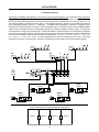
APPLICATIONS
Zone Paging with Background Music & Emergency Override
Programming of the PMX84 for this application can be done by simply opening & downloading a file (page1b.pmx) during Configuration.
This application is identical to the application on the previous page, except that an emergency override signal has been added. The
emergency override signal is connected to Input 8 of the PMX84, and an emergency override switch (or contact-closure) is connected
between the Override terminal and the adjacent ground ( ) on the PMX84. Override is programmed to assign Input 8 to Outputs A~D.
Override maintains a higher priority than any of the Logic Inputs. When Override is activated (shorted to ground), all paging & background
music assignments will be shut off and the emergency override signal will be applied to all outputs. When Override is released (no longer
shorted to ground), the PMX84 will automatically revert to its previous settings, and normal operation. The emergency override signal may
be paging, an alarm, or a siren. If no emergency override signal is connected to Input 8 of the PMX84, the Override terminal will still
provide an override function. Under these circumstances, Override will still shut off all paging & background music assignments, but no
emergency signal will be applied to the outputs.
ý
Zone 3
paging
station
Zone 2
paging
station
E17934
DC out main out main stack main
patch
EX
from
emergency
override
switch
pad
2
3
pad
in
patch
8
remote inputs
1
pad
in
patch
±12VDC 15W
Class 2
logic outputs
IR2
IR3
IR2
IR3
gnd
IR2
IR3
gnd
IR2
IR3
gnd
4
A
expansion
input
+10
8
+10
7
level
+10
1
level
level
+10
C
level
patch
1
2
level
+10
D
expansion
input
3
level
expansion
input
level
patch
logic inputs
in
patch
2
4
level
patch
pad
in
patch
3
background emergency
music
override
signal
inputs
B
expansion
input
~27V 15VA
50/60 Hz
Class 2 wiring
override
pad
in
patch
outputs
Portland, Oregon
an affiliate of Rauland-Borg Corp. MADE IN U.S.A.
serial port
pad
in
patch
5
level
PMX84
pad
in
patch
6
BIAMP SYSTEMS
4
master
paging
station
pad
in
patch
7
patch
gnd
from
paging
station
switches
Zone 1
paging
station
6
level
5
level
+10
+10
level
+10
PMX link
D60EQ
(Zone 3)
ADVANTAGE D60EQ
MADE IN U.S.A.
common
+ input
4Ω
- input
autoformer
input
gnd
115V: 2A SB fuse
230V: 1A SB fuse
ADVANTAGE D60EQ
115V
8Ω
115/230 VAC
F
SE
+ input
4Ω
- input
gnd
* FUS
ADVANTAGE D60EQ
115V
8Ω
115/230 VAC
* FUS
100V
SE
F
SE
- input
gnd
8Ω
100V
50/60 Hz 160 Watts
1 2 3 4
Zone 1
5 6 7 8
Zone 2
17
9 10 11 12
Zone 3
sic
mu
ge
Zone 4
pa
sic
mu
ge
Zone 3
pa
mu
ge
sic
Zone 2
pa
sic
mu
ge
pa
e4
ne
Zo
Zo
n
3
Zone 1
2
ne
1
Zo
ne
+ input
4Ω
70V
E * F
SE *
Zo
common
autoformer
input
115V: 2A SB fuse
230V: 1A SB fuse
U
SE *
all
MADE IN U.S.A.
U
* FUS
70V
F
common
E * F
Master
l-C
SE *
50/60 Hz 160 Watts
50/60 Hz 160 Watts
Al
gnd
100V
D60EQ
(Zone 2)
autoformer
input
115V: 2A SB fuse
230V: 1A SB fuse
- input
8Ω
E * F
U
SE *
ADVANTAGE D60EQ
MADE IN U.S.A.
+ input
4Ω
70V
100V
D60EQ
(Zone 4)
115V
common
autoformer
input
115V: 2A SB fuse
230V: 1A SB fuse
E * F
50/60 Hz 160 Watts
115/230 VAC
MADE IN U.S.A.
U
* FUS
70V
SE
115V
115/230 VAC
D60EQ
(Zone 1)
F
Zone 4
paging
station
13 14 15 16
Zone 4
paging stations
with
routing switches
Logic Inputs
with
priority grouping
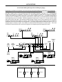
APPLICATIONS
‘In-Line’ Room Combining
Programming of the PMX84 for this application can be done by simply opening & downloading a file (inline4a.pmx) during Configuration.
This application shows (4) rooms in a row (‘inline’). Each room has (2) mics & (1) auxiliary input connected to an Advantage 301e. The
301e mic/line mixers provide mixing, remote level control, auto-muting of aux inputs, and balanced line-level outputs for Rooms 1~4. The
301e outputs for Rooms 1~4 are then connected to Inputs 1~4 of the PMX84, respectively. Outputs A~D of the PMX84 are connected to
inputs of Advantage D60EQs for Rooms 1~4, respectively. The D60EQs provide amplification, equalization, & transformer output
necessary for the distributed speakers in each room. CMA mixer/amplifiers may be used instead of the 301e mixers & D60EQ amplifiers.
A switch on each room partition is wired to the appropriate Logic Input on the PMX84 (see diagram at bottom of page). The Logic Inputs
are programmed for a ‘binary’ (room combining) mode. This allows the PMX84 to recognize the various room combinations, by reading the
status of all three room partition switches. The Logic Inputs are also programmed to perform the input/output assignments associated with
the various room combinations. Eight different room combinations are possible: 1 / 2 / 3 / 4; 1+2 / 3 / 4; 1 / 2+3 / 4; 1 / 2 / 3+4; 1+2 /
3+4; 1+2+3 / 4; 1 / 2+3+4; and 1+2+3+4. This same application can be used when combining only three rooms. Under these
circumstances, use Inputs 1~3 and Outputs A~C for Rooms 1~3 respectively, and Logic Inputs 9 & 10 for the room partition switches.
aux
301e
(Room 3)
BIAMP SYSTEMS
BIAMP SYSTEMS
pad
27 VAC
18W
out
patch
com
+ --
+10V C gnd com
main output
remote
+ --
com
stack input
+
--
com
600
mic/line 3
+
--
com
/ ch. 2
+
in
MADE IN U.S.A.
aux
301e
(Room 4)
BIAMP SYSTEMS
pad
BIAMP SYSTEMS
pad
27 VAC
18W
+10V C gnd com
remote
+ --
stack input
com
+
--
com
600
mic/line 3
from
room
partition
switches
+
--
com
/ ch. 2
+
in
remote inputs
2
3
Portland, Oregon
IR2
IR3
IR2
IR3
gnd
IR2
IR3
gnd
IR2
IR3
gnd
gnd
logic outputs
~27V 15VA
50/60 Hz
Class 2 wiring
remote
+ --
com
stack input
+
logic inputs
600
+
com
ADVANTAGE D60EQ
+
expansion
input
2
MADE IN U.S.A.
common
+ input
4Ω
- input
autoformer
input
gnd
115V: 2A SB fuse
230V: 1A SB fuse
8
7
level
6
level
+10
+10
level
ADVANTAGE D60EQ
115V
8Ω
115/230 VAC
* FUS
70V
50/60 Hz 160 Watts
SE
ADVANTAGE D60EQ
115V
8Ω
115/230 VAC
MADE IN U.S.A.
+ input
4Ω
- input
gnd
8Ω
70V
SE *
* FUS
E * F
U
SE *
100V
F
SE
50/60 Hz 160 Watts
common
autoformer
input
115V: 2A SB fuse
230V: 1A SB fuse
U
* FUS
70V
100V
50/60 Hz 160 Watts
Room Configuration and Logic Input/Switch Assignments
9
Room 2
10
18
Room 3
11
Room 4
common
+ input
4Ω
- input
autoformer
input
gnd
115V: 2A SB fuse
230V: 1A SB fuse
100V
E * F
Room 1
MADE IN U.S.A.
8Ω
70V
E * F
100V
+
--
mic/line 1
+10
SE *
gnd
pad
com
5
level
+10
U
- input
--
/ ch. 2
1
E * F
SE *
+ input
4Ω
+
+10
U
common
600
level
+10
D60EQ
(Room 2)
autoformer
input
com
D60EQ
(Room 1)
D60EQ
(Room 4)
115V: 2A SB fuse
230V: 1A SB fuse
--
--
50/60 Hz 160 Watts
ADVANTAGE D60EQ
+
mic/line 3
* FUS
115V
MADE IN U.S.A.
com
PMX link
115/230 VAC
115V
+ --
stack input
mic/line 1
D60EQ
(Room 3)
115/230 VAC
remote
pad
--
/ ch. 2
level
+10
C
patch
com
level
+10
level
expansion
input
pad
--
mic/line 3
3
level
expansion
input
D
override
+10V C gnd com
4
level
patch
level
patch
serial port
+ --
main output
A
level
expansion
input
+10V C gnd com
inputs
B
an affiliate of Rauland-Borg Corp. MADE IN U.S.A.
patch
PMX84
com
outputs
BIAMP SYSTEMS
4
out
patch
MADE IN U.S.A.
1
+ --
main output
an affiliate of
Rauland-Borg Corp.
--
mic/line 1
SE
+ --
main output
F
com
F
out
patch
com
SE
in
pad
Portland, Oregon
an affiliate of
Rauland-Borg Corp.
MADE IN U.S.A.
out
patch
aux
301e
(Room 2)
pad
Portland, Oregon
pad
an affiliate of
Rauland-Borg Corp.
--
mic/line 1
F
in
pad
Portland, Oregon
an affiliate of
Rauland-Borg Corp.
MADE IN U.S.A.
27 VAC
18W
pad
pad
Portland, Oregon
27 VAC
18W
aux
301e
(Room 1)
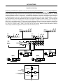
APPLICATIONS
‘In-Line’ Room Combining with Program Sources & Emergency Paging
Programming of the PMX84 for this application can be done by simply opening & downloading a file (inline4b.pmx) during Configuration.
This application is identical to the application on the previous page, except that (2) program sources and an emergency paging signal have
been added. Program sources 1 & 2 are connected to Inputs 5 & 6 of the PMX84, respectively. Logic Inputs 1, 3, 5, & 7 are programmed
to assign Input 5 to Outputs A~D, respectively. Logic Inputs 2, 4, 6, & 8 are programmed to assign Input 6 to Outputs A~D, respectively.
Therefore, two switches may be located in each room, for the selection of program sources 1 & 2. An emergency paging signal is
connected to Input 8 of the PMX84, and an emergency override switch (or contact-closure) is connected between the Override terminal
and the adjacent ground ( ) on the PMX84. Override is programmed to assign Input 8 to Outputs A~D. Override maintains a higher
priority than any of the Logic Inputs. When Override is activated (shorted to ground), all room & source signals will be shut off and the
emergency override signal will be applied to all outputs. When Override is released (no longer shorted to ground), the PMX84 will
automatically revert to its previous settings, and normal operation. The emergency paging signal may instead be an alarm or siren. If no
emergency signal is connected to Input 8 of the PMX84, the Override terminal will still provide an override function. Under these
circumstances, Override will still shut off all room & source signals, but no emergency signal will be applied to the outputs.
ý
aux
301e
(Room 3)
BIAMP SYSTEMS
BIAMP SYSTEMS
pad
27 VAC
18W
in
out
patch
com
+ --
+10V C gnd com
main output
remote
+ --
com
stack input
+
--
com
600
mic/line 3
+
--
com
/ ch. 2
+
in
MADE IN U.S.A.
aux
BIAMP SYSTEMS
pad
BIAMP SYSTEMS
pad
27 VAC
18W
+
--
com
600
mic/line 3
from
emergency
override
switch
+
--
com
/ ch. 2
+
in
out
patch
MADE IN U.S.A.
remote inputs
1
2
3
com
+ --
main output
+10V C gnd com
remote
+ --
com
stack input
+
pad
--
com
600
mic/line 3
outputs
BIAMP SYSTEMS
Portland, Oregon
4
+
A
level
PMX84
logic outputs
patch
com
+
ADVANTAGE D60EQ
C
expansion
input
+10
8
level
patch
+10
7
level
6
level
+10
1
level
level
+10
com
600
+
--
com
/ ch. 2
+
--
mic/line 1
5
level
+10
+10
level
+10
MADE IN U.S.A.
D60EQ
(Room 1)
common
+ input
4Ω
- input
autoformer
input
gnd
115V: 2A SB fuse
230V: 1A SB fuse
ADVANTAGE D60EQ
115V
8Ω
115/230 VAC
SE
- input
gnd
ADVANTAGE D60EQ
115V
8Ω
115/230 VAC
MADE IN U.S.A.
common
+ input
4Ω
- input
autoformer
input
gnd
115V: 2A SB fuse
230V: 1A SB fuse
8Ω
70V
SE
SE *
SE *
* FUS
E * F
U
U
100V
F
SE
50/60 Hz 160 Watts
100V
50/60 Hz 160 Watts
Room Configuration and Logic Input/Switch Assignments
Room 1
9
Room 2
SE *
+ input
4Ω
70V
E * F
10
19
Room 3
11
Room 4
+ input
4Ω
- input
gnd
8Ω
70V
E * F
U
SE *
50/60 Hz 160 Watts
D60EQ
(Room 2)
common
autoformer
input
115V: 2A SB fuse
230V: 1A SB fuse
100V
D60EQ
(Room 4)
common
MADE IN U.S.A.
U
* FUS
70V
E * F
50/60 Hz 160 Watts
autoformer
input
program
source 1
* FUS
115V
* FUS
--
PMX link
115/230 VAC
115V: 2A SB fuse
230V: 1A SB fuse
+
mic/line 3
--
D60EQ
(Room 3)
ADVANTAGE D60EQ
com
mic/line 1
2
level
+10
D
expansion
input
3
level
expansion
input
level
patch
logic inputs
4
level
expansion
input
~27V 15VA
50/60 Hz
Class 2 wiring
from
program
source
switches
MADE IN U.S.A.
+ --
stack input
pad
--
/ ch. 2
inputs
B
an affiliate of Rauland-Borg Corp. MADE IN U.S.A.
patch
override
115V
remote
emergency
paging
signal
program
source 2
serial port
115/230 VAC
+10V C gnd com
an affiliate of
Rauland-Borg Corp.
--
mic/line 1
IR2
IR3
com
IR2
IR3
gnd
+ --
stack input
IR2
IR3
gnd
remote
IR2
IR3
gnd
from
room
partition
switches
+10V C gnd com
gnd
+ --
main output
F
com
F
out
patch
+ --
main output
SE
in
pad
Portland, Oregon
an affiliate of
Rauland-Borg Corp.
MADE IN U.S.A.
com
aux
301e
(Room 2)
pad
Portland, Oregon
out
patch
F
301e
(Room 4)
pad
an affiliate of
Rauland-Borg Corp.
--
mic/line 1
pad
pad
Portland, Oregon
an affiliate of
Rauland-Borg Corp.
MADE IN U.S.A.
27 VAC
18W
pad
pad
Portland, Oregon
27 VAC
18W
aux
301e
(Room 1)
100V
APPLICATIONS
‘Square’ Room Combining
Programming of the PMX84 for this application can be done by simply opening & downloading a file (square1a.pmx) during Configuration.
This application shows (4) rooms in a ‘square’. Each room has (2) mics & (1) auxiliary input connected to an Advantage 301e. The 301e
mic/line mixers provide mixing, remote level control, auto-muting of aux inputs, and balanced line-level outputs for Rooms 1~4. The 301e
outputs for Rooms 1~4 are then connected to Inputs 1~4 of the PMX84, respectively. Outputs A~D of the PMX84 are connected to inputs
of Advantage D60EQs for Rooms 1~4, respectively. The D60EQs provide amplification, equalization, & transformer output necessary for
the distributed speakers in each room. CMA mixer/amplifiers may be used instead of the 301e mixers & D60EQ amplifiers. A switch on
each room partition is wired to the appropriate Logic Input on the PMX84 (see diagram at bottom of page). The Logic Inputs are
programmed for a ‘binary’ (room combining) mode. This allows the PMX84 to recognize the various room combinations, by reading the
status of all four room partition switches. The Logic Inputs are also programmed to perform the input/output assignments associated with
the various room combinations. Twelve practical room combinations are available: 1 / 2 / 3 / 4; 1+2 / 3 / 4; 1 / 2+3 / 4; 1 / 2 / 3+4; 4+1 /
2 / 3; 1+2+3 / 4; 1 / 2+3+4; 1+3+4 / 2; 1+2+4 / 3; 1+2 / 3+4; 1+4 / 2+3; and 1+2+3+4. Whenever a single room partition is closed (no
rooms isolated), the PMX84 is programmed to assume all rooms are combined (1+2+3+4).
aux
301e
(Room 3)
BIAMP SYSTEMS
BIAMP SYSTEMS
pad
27 VAC
18W
out
patch
com
+ --
+10V C gnd com
main output
remote
+ --
com
stack input
+
--
com
600
mic/line 3
+
--
com
/ ch. 2
+
in
MADE IN U.S.A.
aux
301e
(Room 4)
BIAMP SYSTEMS
pad
BIAMP SYSTEMS
pad
27 VAC
18W
+10V C gnd com
remote
+ --
stack input
com
+
--
com
600
mic/line 3
from
room
partition
switches
+
--
com
/ ch. 2
+
in
remote inputs
2
3
Portland, Oregon
IR2
IR3
IR2
IR3
gnd
IR2
IR3
gnd
IR2
IR3
gnd
gnd
logic outputs
~27V 15VA
50/60 Hz
Class 2 wiring
remote
+ --
com
stack input
+
logic inputs
com
600
+
com
ADVANTAGE D60EQ
C
patch
expansion
input
+10
8
MADE IN U.S.A.
6
level
common
+10
+ input
4Ω
level
- input
gnd
ADVANTAGE D60EQ
115V
8Ω
115/230 VAC
* FUS
100V
50/60 Hz 160 Watts
ADVANTAGE D60EQ
SE
115V
8Ω
115/230 VAC
MADE IN U.S.A.
* FUS
SE *
SE *
50/60 Hz 160 Watts
Room 1
9
12
Room 4
Room 2
10
11
20
Room 3
+ input
4Ω
- input
gnd
8Ω
70V
E * F
U
U
100V
F
SE
50/60 Hz 160 Watts
common
autoformer
input
115V: 2A SB fuse
230V: 1A SB fuse
100V
common
+ input
4Ω
- input
autoformer
input
gnd
115V: 2A SB fuse
230V: 1A SB fuse
E * F
E * F
Room
Configuration
and
Logic Input/Switch
Assignments
MADE IN U.S.A.
8Ω
70V
E * F
100V
+
--
mic/line 1
+10
70V
70V
* FUS
pad
com
5
level
+10
SE *
gnd
--
/ ch. 2
--
U
- input
+
D60EQ
(Room 1)
autoformer
input
115V: 2A SB fuse
230V: 1A SB fuse
SE *
+ input
4Ω
+
U
common
600
1
D60EQ
(Room 2)
autoformer
input
com
+10
7
level
+10
D60EQ
(Room 4)
115V: 2A SB fuse
230V: 1A SB fuse
--
level
level
+10
50/60 Hz 160 Watts
ADVANTAGE D60EQ
+
mic/line 3
* FUS
115V
MADE IN U.S.A.
com
PMX link
115/230 VAC
115V
+ --
stack input
mic/line 1
D60EQ
(Room 3)
115/230 VAC
remote
pad
--
/ ch. 2
2
level
+10
level
expansion
input
pad
--
mic/line 3
3
level
expansion
input
D
override
+10V C gnd com
4
level
patch
level
patch
serial port
+ --
main output
A
level
expansion
input
+10V C gnd com
inputs
B
an affiliate of Rauland-Borg Corp. MADE IN U.S.A.
patch
PMX84
com
outputs
BIAMP SYSTEMS
4
out
patch
MADE IN U.S.A.
1
+ --
main output
an affiliate of
Rauland-Borg Corp.
--
mic/line 1
SE
+ --
main output
F
com
F
out
patch
com
SE
in
pad
Portland, Oregon
an affiliate of
Rauland-Borg Corp.
MADE IN U.S.A.
out
patch
aux
301e
(Room 2)
pad
Portland, Oregon
pad
an affiliate of
Rauland-Borg Corp.
--
mic/line 1
F
in
pad
Portland, Oregon
an affiliate of
Rauland-Borg Corp.
MADE IN U.S.A.
27 VAC
18W
pad
pad
Portland, Oregon
27 VAC
18W
aux
301e
(Room 1)
APPLICATIONS
‘Square’ Room Combining with Program Sources & Emergency Paging
Programming of the PMX84 for this application can be done by simply opening & downloading a file (square1b.pmx) during Configuration.
This application is identical to the application on the previous page, except that (2) program sources and an emergency paging signal have
been added. Program sources 1 & 2 are connected to Inputs 5 & 6 of the PMX84, respectively. Logic Inputs 1, 3, 5, & 7 are programmed
to assign Input 5 to Outputs A~D, respectively. Logic Inputs 2, 4, 6, & 8 are programmed to assign Input 6 to Outputs A~D, respectively.
Therefore, two switches may be located in each room, for the selection of program sources 1 & 2. An emergency paging signal is
connected to Input 8 of the PMX84, and an emergency override switch (or contact-closure) is connected between the Override terminal
and the adjacent ground ( ) on the PMX84. Override is programmed to assign Input 8 to Outputs A~D. Override maintains a higher
priority than any of the Logic Inputs. When Override is activated (shorted to ground), all room & source signals will be shut off and the
emergency override signal will be applied to all outputs. When Override is released (no longer shorted to ground), the PMX84 will
automatically revert to its previous settings, and normal operation. The emergency paging signal may instead be an alarm or siren. If no
emergency signal is connected to Input 8 of the PMX84, the Override terminal will still provide an override function. Under these
circumstances, Override will still shut off all room & source signals, but no emergency signal will be applied to the outputs.
ý
aux
301e
(Room 3)
BIAMP SYSTEMS
BIAMP SYSTEMS
pad
27 VAC
18W
out
patch
com
+ --
+10V C gnd com
main output
remote
+ --
com
stack input
+
--
com
600
mic/line 3
+
--
com
/ ch. 2
+
in
MADE IN U.S.A.
aux
301e
(Room 4)
BIAMP SYSTEMS
pad
BIAMP SYSTEMS
pad
27 VAC
18W
+
--
com
600
mic/line 3
from
emergency
override
switch
+
--
com
/ ch. 2
+
in
remote inputs
2
3
Portland, Oregon
A
level
logic outputs
patch
remote
+ --
com
stack input
+
600
+
patch
expansion
input
com
ADVANTAGE D60EQ
2
8
1
+10
7
level
6
level
+10
MADE IN U.S.A.
common
+ input
4Ω
- input
autoformer
input
gnd
115V: 2A SB fuse
230V: 1A SB fuse
+10
ADVANTAGE D60EQ
115V
8Ω
115/230 VAC
* FUS
100V
50/60 Hz 160 Watts
ADVANTAGE D60EQ
SE
115V
8Ω
115/230 VAC
70V
MADE IN U.S.A.
* FUS
SE *
SE
50/60 Hz 160 Watts
Room 1
9
12
Room 4
Room 2
10
11
21
Room 3
+ input
4Ω
- input
gnd
8Ω
70V
E * F
U
SE *
100V
F
SE
50/60 Hz 160 Watts
common
autoformer
input
115V: 2A SB fuse
230V: 1A SB fuse
U
* FUS
--
pad
com
/ ch. 2
+
--
mic/line 1
100V
common
+ input
4Ω
- input
autoformer
input
gnd
115V: 2A SB fuse
230V: 1A SB fuse
E * F
E * F
Room
Configuration
and
Logic Input/Switch
Assignments
MADE IN U.S.A.
8Ω
70V
E * F
SE *
gnd
+
level
U
- input
600
+10
70V
SE *
+ input
4Ω
com
program
source 1
U
common
--
5
level
+10
D60EQ
(Room 2)
autoformer
input
+
mic/line 3
D60EQ
(Room 1)
D60EQ
(Room 4)
115V: 2A SB fuse
230V: 1A SB fuse
com
emergency
paging
signal
program
source 2
--
level
+10
50/60 Hz 160 Watts
ADVANTAGE D60EQ
+ --
stack input
* FUS
115V
115/230 VAC
MADE IN U.S.A.
+
mic/line 1
D60EQ
(Room 3)
115V
remote
PMX link
from
program
source
switches
115/230 VAC
+10V C gnd com
pad
--
/ ch. 2
level
+10
C
level
expansion
input
com
level
+10
D
logic inputs
pad
--
mic/line 3
3
level
expansion
input
level
patch
override
+10V C gnd com
4
level
expansion
input
~27V 15VA
50/60 Hz
Class 2 wiring
serial port
+ --
main output
inputs
B
an affiliate of Rauland-Borg Corp. MADE IN U.S.A.
patch
PMX84
com
outputs
BIAMP SYSTEMS
4
out
patch
MADE IN U.S.A.
1
+ --
main output
an affiliate of
Rauland-Borg Corp.
--
mic/line 1
IR2
IR3
com
IR2
IR3
gnd
+ --
stack input
IR2
IR3
gnd
remote
IR2
IR3
gnd
from
room
partition
switches
+10V C gnd com
gnd
+ --
main output
F
com
F
out
patch
com
SE
in
pad
Portland, Oregon
an affiliate of
Rauland-Borg Corp.
MADE IN U.S.A.
out
patch
aux
301e
(Room 2)
pad
Portland, Oregon
pad
an affiliate of
Rauland-Borg Corp.
--
mic/line 1
F
in
pad
Portland, Oregon
an affiliate of
Rauland-Borg Corp.
MADE IN U.S.A.
27 VAC
18W
pad
pad
Portland, Oregon
27 VAC
18W
aux
301e
(Room 1)
100V
PMX84 Block Diagram
patch
+10
signal
detect
Inputs
1~8
Outputs
A~D
8-by-4
crosspoint
matrix
level
level
2
22
3
Remote
Ports
1~4
4
5
front panel
input/output
assignment
displays (x4)
6
Emergency
Override
Serial
Port
Logic
Inputs
1~16
microprocessor
Logic
Outputs
1~16
7
8
PMX
Link
BLOCK DIAGRAM
1
expansion
input
SPECIFICATIONS
Frequency Response (20Hz~20kHz @ +4dBu):
+0/-0.2dB
Total Harmonic Distortion (20Hz~20kHz @ +4dBu):
< 0.007%
Output Noise (20Hz~20kHz @ unity gain):
one input assigned
-93dBu
eight inputs assigned
-87dBu
Maximum Gain (input & output level controls max.):
+20dB
Input Level Control Range:
-∞~+10dB
Output Level Control Range:
-∞~+10dB
Input Impedance:
input (balanced)
20k ohms
patch (unbalanced - level control dependent)
7k~25k ohms
expansion in (unbalanced)
20k ohms
Maximum Input:
input
+18dBu
patch
+18dBu
expansion in
+18dBu
Output Impedance:
output (balanced)
200 ohms
patch (unbalanced)
50 ohms
Maximum Output:
output (balanced)
+24dBu
patch (unbalanced)
+18dBu
Input Off Attenuation (20Hz~20kHz @ +4dBu):
-60dB
Logic Inputs (TTL compatible):
5V
Logic Outputs (open collector):
24V / 50mA max.
Power Requirements:
115/230V @ 50/60Hz
Power Consumption:
< 15 Watts
Dimensions:
height (2 rack-spaces)
3.5” (89mm)
width
19” (483mm)
depth
7.5” (191mm)
Weight:
8.0 lbs. (3.63kg)
23
WARRANTY
BIAMP SYSTEMS IS PLEASED TO EXTEND THE FOLLOWING 5-YEAR
LIMITED WARRANTY TO THE ORIGINAL PURCHASER OF THE
PROFESSIONAL SOUND EQUIPMENT DESCRIBED IN THIS MANUAL.
BIAMP Systems expressly warrants this product to be
free from defects in material and workmanship for a
period of 5 YEARS from the date of purchase as a
new product from an authorized BIAMP Systems
dealer under the following conditions.
1. The Purchaser is responsible for completing and
mailing to BIAMP Systems, within 10 days of
purchase, the attached warranty application.
2. In the event the warranted BIAMP Systems product
requires service during the warranty period, BIAMP
Systems will repair or replace, at its option, defective
materials, provided you have identified yourself as the
original purchaser of the product to any authorized
BIAMP Systems Service Center. Transportation and
insurance charges to and from an authorized Service
Center or the BIAMP Systems factory for warranted
products or components thereof to obtain repairs shall
be the responsibility of the purchaser.
3. This warranty will be VOIDED if the serial number
has been removed or defaced; or if the product has
been subjected to accidental damage, abuse, rental
usage, alterations, or attempted repair by any person
not authorized by BIAMP Systems to make repairs; or
if the product has been installed contrary to BIAMP
Systems's recommendations.
4. Electro-magnetic fans, electrolytic capacitors, and
the normal wear and tear of appearance items such
as paint, knobs, handles, and covers is not covered
under this warranty.
5. BIAMP SYSTEMS SHALL NOT IN ANY EVENT BE
LIABLE
FOR
SPECIAL,
INCIDENTAL,
OR
CONSEQUENTIAL DAMAGES, INCLUDING LOST
PROFITS, LOSS OF USE, PROPERTY DAMAGE, INJURY
TO GOODWILL, OR OTHER ECONOMIC LOSS OF ANY
SORT. EXCEPT AS EXPRESSLY PROVIDED HEREIN,
BIAMP SYSTEMS DISCLAIMS ALL OTHER LIABILITY TO
PURCHASER OR ANY OTHER PERSONS ARISING OUT
OF USE OR PERFORMANCE OF THE PRODUCT,
INCLUDING LIABILITY FOR NEGLIGENCE OR STRICT
LIABILITY IN TORT.
6. THIS WARRANTY IS IN LIEU OF ALL OTHER
WARRANTIES EXPRESSED OR IMPLIED.
BIAMP
SYSTEMS EXPRESSLY DISCLAIMS ALL IMPLIED
WARRANTIES OF MERCHANTABILITY AND FITNESS
FOR A PARTICULAR PURPOSE. THE REMEDIES SET
FORTH HEREIN SHALL BE THE PURCHASER'S SOLE
AND EXCLUSIVE REMEDIES WITH RESPECT TO ANY
DEFECTIVE PRODUCT. THE AGENTS, EMPLOYEES,
DISTRIBUTORS, AND DEALERS OF BIAMP SYSTEMS
ARE NOT AUTHORIZED TO MODIFY THIS WARRANTY
OR TO MAKE ADDITIONAL WARRANTIES BINDING ON
BIAMP SYSTEMS.
ACCORDINGLY, ADDITIONAL
STATEMENTS SUCH AS DEALER ADVERTISEMENTS
OR REPRESENTATIONS DO NOT CONSTITUTE
WARRANTIES BY BIAMP SYSTEMS.
7. No action for breach of this warranty may be
commenced more than one year after the expiration of this
warranty.
Thank you for purchasing BIAMP SYSTEMS...
AMERICAN SOUND CRAFTSMANSHIP
Biamp Systems
10074 S.W. Arctic Drive
Beaverton, Oregon 97005 U.S.A.
(503) 641-7287
http://www.biamp.com
585.0126.00