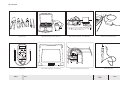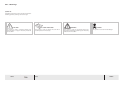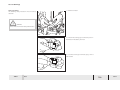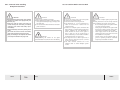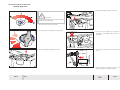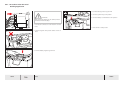
1
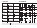
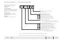
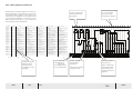
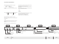
TOURING
INTERCI T Y
Manuale
Collegamenti
Electronics
and wiring Elettrici
manual
TS30
9020-135Y
9020-225Y
Rev.:00
TMSF6L,
APLU5L1TMUF6L
05 April 2013
V
Value in motion
CONTENTS
Foreword ......................................................................................
Power Sysem ................................................................................
Emergency Stop & Flasher & Starter Safety Systems ..............
Engine Control System ...............................................................
Engine Water Cooling & Motorfan Systems .............................
Transmission & Retarder Systems..............................................
Multiplex Sysem ..........................................................................
Displays and Instruments Systems ............................................
Brake System ...............................................................................
ABS & ASR System ........................................................................
Air Suspension System ................................................................
Door Systems ...............................................................................
Air Condition System ..................................................................
Window and Mirror Systems ......................................................
Wiper and Washer Systems ........................................................
Lights System ...............................................................................
Audio-Video & GPS-Navigation Systems....................................
TEMSA
Note:
00
01
02
03
04
05
06
07
08
09
10
11
12
14
15
16
17
Accessories ...................................................................................
Fire Warning System ..................................................................
WC Unit System ...........................................................................
Reverse Gear Buzzer Systems ....................................................
Air Circulation Sistem( in luggage)............................................
Driver Panel Switches Power (cables) .......................................
Invertor System 24V-DC/~110V-AC ..........................................
Appendix
TS30
18
19
20
22
25
26
30
PAGE REVISION CONTROL TABLE
V
V
W
W
: TS-30
: APLU5L1
: 9020-225Y
: 01.March.2013
P AGE REVISION CONTROL TABLE
REVISION
P AGE
TEMSA
REVISION
DA TE
REVISION
NO
SERVICE
BULLETIN NO
DESCRIPTION
TS-30
00.1.1 General Information
The Aim of this User’s Manual
Use of Genuine Parts and Accessories
Service and Maintenance
The Electrical Wiring Manual is prepared to explain
how to service your vehicle in the safest and most
For a safer and longer service life of the vehicle, use
only TEMSA genuine spare parts, accessories or parts
which have been approved and tested by TEMSA.
The service and maintenance operations should be
carried out by authorized services and be in compliance with TEMSA directives.
Safety instructions given in this manual are intended
to protect persons and properties.
All genuine parts have been approved by TEMSA
by means of testing their reliability, endurance and
safety factors.
Therefore, before operating the vehicle or before
carrying out any maintenance work, read this
manual completely and carefully.
Any injury or damage arisen from noncompliance
with the safety instructions given in this manual is
the responsibility of thet vehicle’s owner.
TEMSA does not take any responsibility for any injury
or damage due to use of non-approved third party
products.
Any alteration of the vehicle may interfere with
safety features built into the vehicle and may lead to
an accident resulting in serious injury or death.
This manual is intended to be used commonly for all
variants of TOURMALIN CUMMINS EURO 5. Therefore
some properties of your vehicle may not comply
with those indicated in this manual.
WARNING
Technical information and properties of
the vehicles stated within this Electrical
Wiring Manual are valid on the date of
issue. TEMSA reserves the right to make
any necessary changes to the features of
its products without giving any advance
notice.
00A-1
TS30
Note:
TEMSA
00.1.2 Tools
TEMSA
General Tools
Mitsubishi Diagnostic Tool ( MUT III )
MAN Engine Diagnostic Tool ( MANCAT )
KIBES K-Line Interface Cable
Multimeter
DAF Engine Diagnostic Tool ( DAVIE )
CAT Engine Diagnostic Tool ( CATET )
Connection Wire
Note:
TS35
TS3
5
00A-2
00
00.1.3 Warnings
Symbol List
Operating Instructions in this manual includes the
folowing symbols, warning words and signs:
CAUTION
This symbol is used in conditions which may
cause damage or injury if necessary measures
are not taken.
00A-3
TS35
TS3
5
VISUAL INSPECTION
This symbol is used to inform the user that a
visual inspection is necessary.
Note:
WARNING
This symbol is used in conditions which may
cause severe damage or fatal injury if necessary
measures are not taken.
DANGER
This symbol is used to indicate danger.
TEMSA
00.1.3 Warnings
Safety Precautions
The following safety instructions must be strictly
observed.
1. Hold the connector.
WARNING
To disconnect a connector never pull the harness.
2. To disconnect locking type connectors push it in
the direction indicated by an arrow.
3. To connect a lock type connector, plug it until a
click is heard.
TEMSA
Note:
TS35
00A-4
00
00.1.4 Control Units Handling
& Repair Precautions
CAUTION
Observe the following precautions when handling
or servicing the control units (Engine EDC, Retarder ECU, etc.).
a) Make sure that the control units does not
contact directly with rain-water, car-washing
water etc. If the control units soaks, wipe it
immediately.
b) Avoid unnecessary removal or painting of the
cover.
c) To remove the control unit from the vehicle,
follow steps mentioned in the page 0-08.
d) Apply arc welding for the repair of the vehicle
parts steps mentioned in the page 0-09.
00A-5
TS35
00.1.5 Cautions Before Service Work
CAUTION
Cautions during washing the vehicle:
a) Before washing the vehicle, make every electrical equipment waterproof (by covering it with
vinyl sheet etc.)
b) Do not wash the electrical harness and waterproof connectors.
CAUTION
During washing the vehicle do not splash
pressured water in Fuse Room and to the battery.
Note:
CAUTIONS
Be sure to use correct tools in the correct place
for servicing as mentioned below :
a) Use Fuse Holder for removing of fuses.
b) Use Multimeter or a 24 V Controllamp to
search for short-circuits if vehicle has not
multiplex system.
c) If there is a multiplex system, remember that
there is always 12 V check voltage in Diagnostic
System. Therefore use only Multimeter to
check whether the circuit of the system is
short or open. Do not use Control lamp or
others. Otherwise you could make a mistake to
understand the short or open circuit.
d) Use diagnostic tool to check Engine EDC or
UPEC. (Note: A diagnostic tool for Cummins
Engine is not existing ).
e) Use Kibes Runtime Software and K-Line
interface cable to check Multiplex system
control.
CAUTION
Precautions for multiplex System program installation
Following instructions must be strictly observed
during installation of program to the system.
Do not install program to the system if there
is a person under the vehicle.
If the program installed to the system while
the vehicle is in lifting position, lifting valves
can release air and vehicle can go down.
Power supply should not be closed while
installing program to the system. Wait until
the installation is completed.
Program should not be installed while engine is in operating conditions. Otherwise
engine stops unsuitable conditions.
TEMSA
00.1.6 Cautions Before Service Work
Multiplex System Functional Checks
CAUTION
External node diagnosis:
To AUS_ID_PLUS, a 2 W bulb in connection
with a 24 V power supply can be connected
for functional checks.
ON
normal operation
OFF
fail safe operation
Configuration
request
200 ms
400 ms
Error Conditions
1500 ms
Cause of Failure
“FAIL SAFE” Operation
CAN-connection failed during operation
Incorrct node ID, incorrect node type or new node (node yet
programmed)
OFF
Voltage Supply or CAN already defective or not present when
turning on or node defective.
ON
Node defective, Voltage supply OK.
Ground
24 V Check Lamp
Connector
TEMSA
Note:
TS35
00A-6
00
00.1.5 Cautions Before Service Work
CAUTIONS
Before servicing of electrical systems follow
the below mentioned steps:
Turn the Ignition key to OFF position.
Turn the Battery Cut Off switch to ON
position.
Check the system failure.
Note: Remember that Battery Cut Off Switch
is an OPTION.
00A-7
TS35
5
Note:
CAUTIONS
Before servicing of Electronic Control
Units(ECU) follow the below mentioned steps:
Turn the Ignition key to OFF position.
Turn the Battery Cut Off switch to ON
position.
Disconnet all connectors of Electronic
Control Unit
Check the system failure.
Note: Remember that Battery Cut Off Switch
is an OPTION.
TEMSA
00.1.6 Procedures for Electrical
Welding Application
4. Disconnect Battery positive (+) terminal.
CAUTIONS
Before electrical welding of the vehicle, follow
the below mentioned steps
1. Turn the ignition tey to OFF position.
2. Turn the battery cut off switch to ON position.
5. Touch and joint negative and positive cables
of vehicle to discharge static electric in the
harnesses.
3. Disconnect Battery negative (-) terminal.
6. Disconnect connectors of all Electronic Control
Units.
welding prosses can be applied safely.
TEMSA
Note:
TS35
5
00A-8
00
00.1.7 Procedures After Electrical
Welding Application
4. Connect Battery positive (+) terminal
5. Turn the ignition key to ON position.
CAUTIONS
After electrical welding of the vehicle, follow
the below mentioned steps
6. Turn the Battery Cut-Off switch to OFF position.
1. Connect all connectors of all Electronic Control
Units.
7. Now vehicle is ready to start.
2. Disjoint negative and positive cables of the vehicle.
3. Connect Battery negative (-) terminal.
00A-9
TS35
5
Note:
TEMSA
00.1.8 Possible failure causes for KIBES 32 products
CAUTION
- Welding on the vehicle when KIBES-32 products are connected to the harness of
the vehicle
- Vehicle has been struck by lightning
- ESD (electro-static discharge) by touching of connector pins by a person without
protection
against ESD (e.g. ESD shoes)
- Exchange of KIBES-32 product during connection to power.
(Before exchange, the KIBES-32 product has to be disconnected from power [e.g.
switch off
battery])
- Overstress of outputs of KIBES-32 products.
Some examples on base of the MUX2-B or MUX2-M are described below.
TEMSA
Note:
TS35
5
00A-10
00
00.1.9 Symbols of Switch Lens
Glass Heater Switch
Auxiliary Lamp Switch
Roof Heater Fan Motor
Switch
Mirror Heater Switch
Room Lamp Switch
Reverse Gear Horn
Cancel Switch
Hazard Switch
Reading Lamp Switch
Door Buzzer Cancel
Switch
Destination Plate Lamp
Driver Lamp Switch
School Bus Lamp Switch
WC Power Switch
Bus Stop Brake Switch
Electrical Curtain Switch
Convector Control
Switch
Engine Start-Stop
Switch
Economy Switch
UDS Switch
Stairs Fan Control
Switch
Retarder Switch
Park & Room Lamp
Switch
Wiper Water Switch
Auto Lubricate
Front Fog Lamp Switch
Front Door Switch
Horn Signal
Rear Fog Lamp Switch
Rear Door Switch
Central Lock Switch
Motorfan Floor Switch
Driver Glass Switch
Lifting Switch
WC
ASR Switch
Exhaust Brake Switch
ABS Switch
STOP
START
UDS
Preheater Switch
00A-11
TS35
Note:
TEMSA
00.2.1 How to Use This Manual
This manual consists of following parts.
1) General Information
2) System Chapters
3) Appendix
On General Information
Cautions before service work, warnings, symbols of
!
shown.
00.2.2 Coding system of the Manual
XX.XX.X.X-X
Indicates the page number of the chapter
For example: x-1, x-2, t-1
On System Chapters
Wiring diagrams, locations of components,
"#$
diagrams are shown,
On Appendix
Locations of fuses on relay panels are shown,
Indicates the chapter of the system
w: indicates the wiring diagram
l: indicates locations of the components
s: indicates specifications of the components
t: indicates the troubleshooting of the system
o: indicates the OEM wiring diagram of the system
Indicates the parts of the system
For example: “A” indicates transmission system for Voith option
“B” indicates transmission system for ZF Astronic option
Indicates the engine type of the vehicle
00: indicates that chapter is valid for all types of engines
01: indicates that chapter is valid for DAF engines
02: indicates that chapter is valid for MAN engines
03: indicates that chapter is valid for CAT engines
04: indicates that chapter is valid for CUMMINS engines
05: indicates that chapter is valid for MITSUBISHI engines
Indicates the name of the system
For example: “03” indicates engine control system
“09” indicates ABS/ASR System
08.05.A.w-1: Indicates the brake system mitsubishi engine exhaust brake system wiring diagram page 1.
08.05.B.w-1: Indicates the brake system mitsubishi engine park brake system wiring diagram page 1.
TEMSA
Note:
TS35
5
00B-1
00
Relais Batteriesteuerung
Starter
Starter
Démarreur
Starter
Alternatör Beslemesi
Alternator Power
Lichtmaschinenstrom
Alimentation De L'Alternateur
Alimentazione Alternatore
01MF003
18
Marş Motoru Beslemesi
Starter Power
Starter Strom
Alimentation Du Demarreur
Alimentazione Starter
Alimentazione Condizionatore
D'Aria
Lift Unit Power
Strom Hebeeinheit
Puissance Du Mecanisme De
Levage
Alimentazione Unita'
Sollevamento
Ön Röle Paneli Kl15 Beslemesi
Front Relay Panel Kl 15 Power
Strom Kl 15 Relaistafel Vorne
Puissance Du Panneau De Relais
Avant Kl 15
Alimentazione Pannello Rele'
Anteriore Kl 15
01MF024
9
Alternatör Beslemesi 2
Alternator Power 2
Strom Lichtmaschine 2
Puissance D'Alternateur 2
Alimentazione Alternatore 2
01S001
7
El Kumandali, Ana, Akü Şalteri
Main Manual Battery Switch
Handhauptschalter Batterien
Interrupteur Principal À Main
Batteries
Interruttore Manuale Principale
Batteria
Akü Şarj Soketi
Battery Charge Connector
Batterieladeanschluss
Connecteur Du Chargeur De
Batterie
Connettore Carica Batteria
10
05A005
07P003
J1
Acil Durum Şalteri
Emergency Stop Switch
Notstopschalter
Interrupteur Arret D'Urgence
Interruttore Arresto Di Emergenza
Motor Giriş Hava Isiticisi Rölesi
Air Intake Heater Relay
Relais Heizung Luftansaugung
Relay Chauffage Admission D'Air
Rele' Aria Di Aspirazione
Riscaldatore
17
Retarder (Telma) Kumanda
Modülü
Retarder Control Module (Telma)
Steuermodul Retarder (Telma)
Module De Commande
Retardateur (Telma)
Modulo Di Controllo Retarder
(Telma)
6
Takograf (Dtco Veya Mtco)
Tachograph (Dtco Or Mtco)
Fahrtschreiber
Enregistreur De Trajets
Tachigrafo (Dtco O Mtco)
12A007
18
32X001w
25
Klima Tavan Ünitesi (Safkar
Ruthart)
Hvac Roof Control Module (Safkar
Ruthart)
Hvac-Dachsteuermodul (SafkarRuthart)
Module De Commande De Toit
Hvac (Safkar Ruthart)
Modulo Di Controllo Tetto Hvac
(Safkar Ruthart)
Engelliler Asansörü Sistemi Tesisati
Handicapped Lift System Harness
Kabelbaum Rollstuhllift
Securisation Du Mecanisme De
Levage Pour Handicapes
Cinghia Sistema Per Ascensore Per
Disabili
KL
KL
KL
KL
Tourmalin
Note:
22
J7
J8
23
24
J3
J4
J5
02S009
07P003
01G004
01G003
03K008
01M001
01K015
05A005
02.04.A.w-1
07.04.A.w-7
01.04.B.w-3
01.04.B.w-3
03.04.A.w-3
01.04.B.w-3
01.04.B.w-2
05.04.B.w-1
5
6
7
8
9
J6
J9
J10
12A007
32X001
2
3
4
10
11
12
13
14
15
16
17
18
19
20
21
22
23
24
25
TEMSA
TEMSA
Note:
Tourmalin
01.04.B.w-1
25/11/2009 Rev:00
KL 31: Chassis Line
KL 58: Park Lamp
Power Line
KL 30: Battery Power
KL 15: Ignition Power
The table shows the
codes that are on
the diagram in many
languages.
00B-2
25
31
58
30
15
1
01.04.B.w-1
J2
(2 Br)
5
03K008
(8R)
3-4
02S009
( 10 R )
01X001
01X001
( 10 RW )
Lift Ünitesi Beslemesi
19
(4R)
25
01MF023
( 10 R )
01MF022
21
50 A
Alimentazione 1 Kl30
Alimentazione Retarder
01MF009
Alimentation 1 Du Kl30
Puissance Du Ralentisseur
20
300 A
Strom 1 Kl30
Retarder Strom
01MF003
Kl30 Power 1
Retarder Power
125 A
Kl30 Beslemesi 1
Retarder Beslemesi
01MF002
19
17
01MF019
Alimentazione Pannello Rele' Kl15
01MF009
01MF019
19
95 (R)
Alimentation Du Climatiseur
Alimentation Du Panneau Des
Relais Kl15
125 A
Strom Klimaanlage
Relaistafel Strom Kl15
01MF024
Air Conditioner Power
Relay Panel Kl15 Power
95 (R)
Klima Tavan Ünitesi Beslemesi
Röle Paneli Kl15 Beslemesi
Rele' Controllo Batteria
22-90 (2,5R)
18
20
18
+
22-90 (2,5R)
01MF006
17
50 A
Battery Control Relay
Marş Motoru
8
16
70 (W)
12 V
_
+
15
01MF022
Akü Kontrol Rölesi
10
01MF002
14
01K006
( 8 RW )
16
01M001
13
( 6 RW )
01K015
12 V
_
12
( 8 RW )
Relais De Commande De Batterie
13-14
11
100 A
Rele' Batterie Motorino Di
Avviamento
01K006
10
( 8 RW )
Alternatore 2
Relais Batteries De Démarrage
9
100 A
Alternatore 1
Alternateur 2
Relais Starterbatterien
8
01MF007
Alternateur 1
Generator 2
Starter Batteries Relay
7
01S001
( 10 RW )
Generator 1
Alternator 2
Start Aküleri Rölesi
6
125 A
Alternator 1
Alternatör 2
5
01G002
01MF023
Alternatör 1
7
4
200 A
8
01G004
3
01MF006
01G003
2
01G001
22-05
Batteria 2
(2 Br)
Batteria 1
Batterie1
01MF007
1
Italiano
Batterie1
01 to 25: indicates
the position of the
component on diagram.
(2 Br)
Français
Batterie 1
Batterie 1
22-90A
Deutsch
Battery 1
Battery 2
95 (R)
English
Akü 1
Akü 2
95 (R)
Türkçe
2
4-5
95 (B)
Part No
01G001
01G002
95 (B)
Code
01G001: Indicates the
code number for the
component.
22-05
While looking to the wiring diagram on manual, you
will see two pages. On the right hand side you will
see electrical wiring diagram. Some symbols and
codes exsits on the diagram. On the left hand side
you will see the explanations of the codes on the
<!
TS35
Note:
07P003: Indicates
the code of the
component.
07.04.A.w-7: Indicates
the page number.
01MF003: indicates
the fuse name.
300 A: indicates the
amper value of fuse.
;
location are shown in
appendix.
TS35
TEMSA
01
Wire characteristic as illustrated in Figure A.
Background: White
25-01
: Wire Code
2,5
: Wire Size 2,5 mm•
If there is not any number in parenthesis, wire size
is 1mm2.
Shield wires are indicated as shown bellow (Figure C)
to distinguish them from other wires.
Wire colours are shown with the capital letter of
each colour.
When the capital letters of the colours are the same,
=
R Red
L Blue
Br Brown
25-01
25-01
25-01A
25-01B
Where a stripe is added to the wire colour, a combination of two capital letters is used.e.g. :
RY (Yellow stripe on red background)
WB (Black stripe on white background)
Wire characteristic as illustrated in Figure B
Wire size is indicated with the cross sectional area
of conductor.
2.5RW
2,5: Cross sectional area of conductor is 2,5 mm².
RW: Background colour is RED, Stripe colour is
WHITE
No wire size is shown for a shielding wire but is
marked with “SHIELD” and wires encased in the
shield are shown in anellipse of line.
A
B
C
D
E
2,5RW
25 -01 (2,5)
B (Stripe)
Stripe Colour
Wire Size
Shield
Isolation of Conductor
Wire Code
Wire Size
Background
W
Background
Colour
Background colour
Wire core Conductor (+)
(
)
(White)
TEMSA
Note:
TS35
5
00B-3
00
BACKGROUND & STRIPE COLOURS
B
Black
LgR
Light Green/Red
VY
Violet/Yellow
BG
Blcak/Green
LgY
Light Green/Yellow
W
White
BL
Black/Blue
LgW
Light Green/White
WB
White/Black
BR
Black/Red
LO
Blue/Orange
WG
White/Green
Br
Brown
LR
Blue/Red
WL
White/Blue
BrB
Brown/Black
LW
Blue/White
WR
White/Red
BrW
Brown/White
LY
Blue/Yellow
Y
Yellow
BrR
Brown/Red
O
Orange
YB
Yellow/Black
BW
Black/White
OL
Orange/Blue
YG
Yellow/Green
BY
Black/Yellow
P
Pink
YL
Yellow/Blue
BrY
Brown/Yellow
PB
Pink/Black
YR
Yellow/Red
G
Green
PG
Pink/Green
YW
Yellow/White
GB
Green/Black
R
Red
GL
Green/Blue
RB
Red/Black
GR
Green/Red
RG
Red/Green
GY
Green/Yellow
RL
Red/Blue
GW
Green/White
RW
Red/White
L
Blue
RY
Red/Yellow
LB
Blue/Black
V
Violet
LG
Blue/Green
VG
Violet/Green
Lg
Light Green
VR
Violet/Red
LgB
Light Green/Black
VW
Violet/White
00B-4
TS30
Note:
TEMSA
00C. WIRING HARNESS CONFIGURATIONS
CONTENT
Chassis Wiring Harness .....................................................................................................................................................................................................00C-2
Roof Wiring Harness ..........................................................................................................................................................................................................00C-3
Engine Room Wiring Harness ...........................................................................................................................................................................................00C-4
Front Body Wiring Harness................................................................................................................................................................................................00C-6
A/C Wiring Harness ...........................................................................................................................................................................................................00C-7
Dashboard Wiring Harness ...............................................................................................................................................................................................00C-8
SwitchBox Wiring Harness.................................................................................................................................................................................................00C-10
Socket Connection Places .................................................................................................................................................................................................00C-11
Spare Cable (Chassis Wiring Harness) ..............................................................................................................................................................................00C-12
Spare Cable (Engine Room Wiring Harness) ....................................................................................................................................................................00C-13
TEMSA
Note :
TS 30
00C-1
CHASSIS WIRING HARNESS
20
28
26
25
22
12
12
28
28
17
19
18
7
15
23
25
5
10
14
12
28
4
11
11
FRONT
REAR
13
15
6
30
30
16
11
8
28
2
14
1
5
3
25
NO
4
9
29
26
IDENTIFICATION
NO
Front Door Step Lamp
11
28
12
12
2
28
1
3
27
24
25
26
21
IDENTIFICATION
Luggage Lamp
NO
22
Rear Relay & Fuse Room Lamp
21
28
IDENTIFICATION
Door Micro Switch
2
Front Door Valve
12
Luggage Lamp Switch
3
Front Door Pressure Switch
13
Air Dryer
23
Front Relay & Fuse Room Lamp
4
Brake Lining Sensor ( Front )
14
ABS Sensor ( Rear )
24
Kneeling Warning Lamp
5
ABS Sensor ( Front )
15
Brake Lining Sensor ( Rear )
25
Rerverse Gear Lamp
6
ABS Valve ( Front )
16
ABS Valve ( Rear )
26
Signal Lamp
7
Lifting Valve
17
Rear Relay & Fuse Panel
27
Door Micro Safety Switch
8
Kneeling Valve
18
Diagnose Socket (Preheater)
28
Marker Lamp
9
Fuel Tank Level Sensor
19
Preheater Water Pump
29
Diesel Particle Filter
Front Relay & Fuse Panel
20
Roof / Floor Water Valve
30
Fire Warning Sensor
10
TEMSA
12
Note :
TS 30
00C-2
ROOF WIRING HARNESS
FRONT
REAR
15
1
7
1
14
1
13
3
7
7
9
12
10
9
12
9
10
12
11
9
10
9
10
12
11
9
10
11
12
9
10
11
9
10
12
10
9
11
12
10
9
13
10
12
11
13
5
6
7
8
10
8
10
8
10
8
10
8
10
8
10
8
10
8
10
8
10
8
10
8
4
7
NO
1
2
3
4
5
TEMSA
IDENTIFICATION
Position Lamp (Right Side)(Top)
Position Lamp (Left Side)(Top)
Front Door Upper Lamp
Driver Lamp
Monitor Supply
NO
6
7
8
9
10
IDENTIFICATION
Clock
Position Lamp (Front) (Top)
Left Speaker
Right Speaker
Reading Lamp
13
13
2
2
2
10
NO
11
12
13
14
15
IDENTIFICATION
Auxiliary Lamps
Interior Lighting Lamps
Position Lamp (Reart) (Top)
Front Door Valve
Front Door Pressure Switch
Note :
TS 30
00C-3
ENGINE ROOM WIRING HARNESS
NO
1
Engine Room Safety Switch
2
Fire Warning Sensor
3
Antifreeze Tank Level Sensor
4
Engine Room Lamps
5
Rear Signal Lamps
6
Stop & Park Lamp
5
7
Park Lamp
6
6
8
Reverse Gear Lamp
7
7
Reverse Gear Buzzer
8
8
9
10
11
12
13
14
15
13
4
11
1
5
10
9
2
12
TEMSA
IDENTIFICATION
4
4
2
Start-Stop Switch
To Wc Unit
Trailer Socket (Option)
3rd Stop Lamp
MUX 2.1
Coolant Level Sensor
Note :
TS 30
00C-4
ENGINE ROOM WIRING HARNESS
11
2
1
13
3
4
4
14
10
8
12
9
5
7
6
NO
1
2
3
4
5
TEMSA
IDENTIFICATION
Engine Room Safety Switch
Head Lamps (Right)(Rear)
Coolant Level Sensor
Engine Room Lamps
Rear Fuse and Relay Panel
NO
6
7
8
9
10
IDENTIFICATION
Head Lamps (Left)(Rear)
Radiator Valve
Fire Warning Sensor
Reverse Gear Buzzer
Start-Stop Switch
NO
11
12
13
14
15
IDENTIFICATION
To Wc Unit
Alternator 1
Alternator 2
Foot Lamp
Note :
TS 30
00C-5
FRONT BODY WIRING HARNESS
NO
1
2
3
4
5
6
7
8
9
10
11
6
Spot Lamp
Fog Lamp (Option)
Horn
Outside Temperature Sensor
Stop Lamp Switch 1 (Brake Pedal)
Stop Lamp Switch 2 (Brake Pedal)
Air Sensör 1 (Brake Pedal)
Air Sensör 2 (Brake Pedal)
10
3
1
2
5
4
TEMSA
IDENTIFICATION
Head Lamps (Low)
Head Lamps (High)
Signal Lamp
6
8
7
9
2
3
1
11
5
4
Note :
TS 30
00C-6
A/C WIRING HARNESS
3
15
17
2
15
8
6
7
10
1
12
TEMSA
9
14
13
11
5
4
NO
1
2
3
4
5
6
7
8
9
10
IDENTIFICATION
A/C Control Panel (Termoking)
A/C Control Unit
A/C Compressor
Roof Water Valve
Floor Water Valve
Diagnose Socket (Preheater)
Power Socket (Preheater)
Fire Warning Sensor
Preheater Water Pump
3 Way Valve (Water)
NO
11
12
13
14
15
16
17
18
IDENTIFICATION
Defroster Unit
Front Relay Panel
Floor Temperature Sensor
Hot water Temperature Sensor
Ambient Temperature Sensor
Return air Temperature Sensor
Coil Temperature Sensor
Duct Temperature Sensor
Note :
TS 30
00C-7
DASHBOARD WIRING HARNESS
NO
1
Left Switch Group
2
Left Column Switch
3
MOKI & Warning Lamp s
4
Retarder Column Switch
5
Right Switch Group
6
Brake Pedal
7
A/C Contol Unit
8
Mux 1.2 & Mux 1.3
9
10
Accelerator Pedal
11
Vehicle Diagnos Socket
10
12
Emergency Stop Switch
13
13
Wiper Motor
14
Defroster
15
Kneeling Warning Lamp
16
Horns
17
Head Lamps Group (Left)
18
Head Lamps Group (Right)
12
5
1
3
7
4
8
14
11
15
9
6
17
16
18
16
TEMSA
IDENTIFICATION
Ignition Key
Note :
TS 30
00C-8
DASHBOARD WIRING HARNESS
1
2
NO
8
3
7
4
5
9
6
10
1
Head Lamp Group (Left)
2
Head Lamp Group (Right)
3
Left Switch Group
4
Left Column Switch
5
Warning Lamps
6
Retarder Column Switch
7
Accelerator Pedal
8
Right Switch Group
9
A/C Control Unit
10
TEMSA
IDENTIFICATION
To Relay and Fuse Panel
Note :
TS 30
00C-9
SWITCHBOX WIRING HARNESS
6
5
3
4
NO
1
2
3
4
5
6
7
8
9
10
11
11
2
1
9
IDENTIFICATION
Driver Speaker
Mirror Control
Parking Brake Switch
12V Plug
Cigarette Lighter
Wiper Water Motor
Marker Lamp
Luggage Lamp
Luggage Lamp Switch
K-line Socket
10
7
8
TEMSA
Note :
TS 30
00C-10
SOCKET CONNECTION PLACES
in switchbox
in front
electrical room
FRONT
REAR
2
1
3
NO
1
2
3
5
6
FRONT
IDENTIFICATION
C13-01, C13-02, C13-03, C13-04, C13-05, C13-10, C14-01, C14-02, C14-03, C14-04,
C14-08, C14-10, C14-11, FAN, INVERTER
C46-01, C46-02, C46-03, CHASIS, C66-01, C66-02
C33-01, C33-02, C-33-03, C35-01, C35-02, C-35-03, ALLISON
C35-05
C35-06
in rear
electrical room
REAR
5
4
TEMSA
Note :
TS 30
00C-11
SPARE CABLE ( CHASSIS & ENGINE ROOM WIRING HARNESS )
REAR
FRONT
3
in rear
electrical room
2
1
in front
electrical room
4
NO
1
2
3
4
TEMSA
IDENTIFICATION
SP-01, SP-02, SP-03, SP-04, SP-05, SP-06, SP-07, SP-08, SP-09, SP-10, SP-11, SP12, SP-13, SP-14, SP-15, SP-16,
SP-01, SP-02, SP-03, SP-04, SP-05, SP-06, SP-07, SP-08, SP-09, SP-10, SP-11, SP12, SP-13, SP-14, SP-15, SP-16,
SP-01, SP-02, SP-03, SP-04, SP-05, SP-06, SP-07, SP-08, SP-09, SP-10, SP-11, SP12, SP-13, SP-14, SP-15, SP-16,
SP-01, SP-02, SP-03, SP-04, SP-05, SP-06, SP-07, SP-08, SP-09, SP-10, SP-11, SP12, SP-13, SP-14, SP-15, SP-16,
SOCKET
F.BODY
F.BODY
E.ROOM
E.ROOM
Note :
TS 30
00C-12