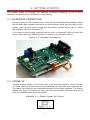
1
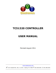
TC55472 CONTROLLER USER MANUAL Revised July, 2013 www.tvielectronics.com 2211 Rayford Rd., Ste. 111-332 Spring, TX 77386 281-408-4051 281-408-4052 User Manual July 2013 THIS PAGE INTENTIONALLY LEFT BLANK Copyright © 2013, TVI Electronics LLC. IMPORTANT NOTICE TVI Electronics shall not be liable in any action against it in any way related to the products or software for any loss or damages, whether non-specified direct, indirect, special, incidental or consequential (including downtime, loss of profits or goodwill) regardless of the legal theory asserted. TVI Electronics reserves the right to make corrections, modifications, enhancements, improvements, and other changes to its products and services at any time and to discontinue any product or service without notice. Customers should obtain the latest relevant information before placing orders and should verify that such information is current and complete. All products sold by TVI Electronics are subject to company's terms and conditions of sale supplied at the time of order acknowledgment. User is responsible for determining whether the TVI Electronics products and software are fit for User’s particular purpose and suitable for its method of production, including intellectual property liability for User's application. Copyright © 2013, TVI Electronics LLC. WARRANTY TVI Electronics warrants performance of its hardware products to the specifications applicable at the time of sale in accordance with TVI Electronics’ standard warranty. All TVI Electronics products have been manufactured to your company's or your own specifications as a part for use in your company's or own general electronic products. It is guaranteed to perform according to delivery specifications. This evaluation board being sold by TVI Electronics is intended for use for ENGINEERING DEVELOPMENT OR EVALUATION PURPOSES ONLY. We cannot take responsibility if the product is used in medical devices, nuclear power control equipment, aerospace equipment, fire and security systems, or any other applications in which there is a direct risk to human life and where extremely high levels of reliability are required. 1. We cannot accept responsibility for any defect, which may arise from additional manufacturing of the product (including disassembly and reassembly), after product delivery. 2. We cannot accept responsibility for any defect, which may arise after the application of strong external force to the product. 3. We cannot accept responsibility for any defect, which may arise due to the application of static electricity after the product has passed your company's acceptance inspection procedures. Customers are responsible for their products and applications using TVI Electronics components. To minimize the risks associated with customer products and applications, customers should provide adequate design and operating safeguards. Copyright © 2013, TVI Electronics LLC. TOUCH SCREEN LCD MODULE HANDLING PRECAUTIONS The following precautions will guide you in handling of our product correctly: 1. Liquid crystal display devices: 1.1. The liquid crystal display device panel used in the liquid crystal display module is made of plate glass. Avoid any strong mechanical shock on LCD and touch screen. Should the glass break, handle it with care. 1.2. The polarizer adhering to the surface of the LCD is made of a soft material. Guard against scratching it. 1.3. Wash your hands or clothes if you touch liquid crystal! 2. Avoid Static electricity! 2.1. When working with the module, use your naked or gloved hand and wear nonconductive work suit to prevent generating static electricity by friction. ESD ground straps should be utilized. 2.2. Be sure to ground any electrical appliances you may be using, such as soldering iron, cutting pliers, tweezers, etc. 2.3. Floors, doors, and work tables must be grounded to discharge electricity. 3. When the LCD module alone must be stored for long periods of time: 3.1. Protect the modules from high temperature and humidity. 3.2. Keep the modules out of direct sunlight or direct exposure to ultraviolet rays. 3.3. Protect the modules from excessive external forces. 4. Use the module with a power supply that is equipped with an over current protector circuit, since the module is not provided with this protective feature. 5. Do not ingest the LCD fluid itself should it leak out of a damaged LCD module. Should hands or clothing come in contact with LCD fluid, wash immediately with soap. 6. Conductivity is not guaranteed for models that use metal holders where solder connections between the metal holder and the PCB are not used. 7. Do not stack up modules since they can be damaged by components on neighboring modules. 8. Do not place heavy objects on top of the product. This could cause glass breakage. 9. Do not scratch LCD or touch screen! 10. In order to maintain module reliability, do not touch or hold by the connector area. 11. Avoid any bending, pulling, or other excessive force on flexible cables, which can result in broken connections. 12. ATTENTION!!! AVOID DISCONNECTING TOUCH SCREEN FROM THE J8B CONNECTOR! Copyright © 2013, TVI Electronics LLC. PREFACE About This Manual This user's manual describes the function and operation of the TC55472 controller Firmware v1.0 and higher. This manual will help you quickly set up the touch screen controller evaluation board and its accompanying software, so that you can rapidly test and evaluate their usefulness for your application. If You Need an Assistance If you have any questions about this evaluation board, feel free to e−mail TVI Electronics Support Team at [email protected]. Include the product name in the subject heading. Copyright Copyright © 2013, TVI Electronics LLC. All rights reserved. TVI Electronics reserves the right to make changes and improvements to its product without notification. Notice to Users When a system failure may cause serious consequences, protecting life and property against such consequences with a backup system or safety device is essential. The user agrees that protection against consequences resulting from system failure is the user's responsibility. This device is not approved for lifesupport or medical systems. Copyright © 2013, TVI Electronics LLC. DOCUMENT CONVENTIONS The following icons are used as necessary to distinguish elements of text. NOTE. Notes emphasize additional information that may be useful to the reader. MANDATORY ACTION. Gives directions that, if not observed, could result in loss of data or in damage to equipment. Copyright © 2013, TVI Electronics LLC. CONTENTS 1. FUNCTIONS AND STRUCTURE........................................................................................................ 1 1.1. GENERAL ............................................................................................................................................. 1 1.2. FEATURES ............................................................................................................................................ 1 1.2.1. RS-232 communication interface with nine programmable baud rates ................................. 1 1.2.2. 512k bites external EEPROM .................................................................................................... 1 1.2.3. Touch screen controller ............................................................................................................ 1 1.2.4. AVRISP interface ...................................................................................................................... 1 1.2.5. Draw/Clear Line/Rectangle/Circle ........................................................................................... 1 1.2.6. Voltage regulator ..................................................................................................................... 2 1.2.7. Software control ...................................................................................................................... 2 1.2.8. Hardware contrast adjustment................................................................................................ 2 1.2.9. Fonts ......................................................................................................................................... 2 1.2.10. Spare pins on Atmega16 .......................................................................................................... 2 1.2.11. Firmware update...................................................................................................................... 2 1.3. POWER REQUIREMENTS ......................................................................................................................... 2 2. GETTING STARTED ........................................................................................................................ 3 2.1. 2.2. 2.3. 3. HARDWARE CONNECTION ....................................................................................................................... 3 POWER UP .......................................................................................................................................... 3 QUICK START ....................................................................................................................................... 4 OPERATION .................................................................................................................................. 5 3.1. TC55472 CONTROLLER JUMPERS AND SWITCHES ...................................................................................... 5 3.1.1. Serial Communication .............................................................................................................. 6 3.1.2. Baud Rate Settings ................................................................................................................... 7 3.1.3. Contrast Regulation ................................................................................................................. 7 3.1.4. Firmware Update ..................................................................................................................... 7 3.2. TC55472 COMMANDS LIST ................................................................................................................... 8 4. ELECTRICAL SPECIFICATIONS ....................................................................................................... 15 4.1. 4.2. 5. MODULE POWER CONSUMPTION ............................................................................................................ 15 TC55472 CONTROLLER OPERATING TEMPERATURE ................................................................................... 15 MECHANICAL SPECIFICATIONS .................................................................................................... 16 5.1. TOUCH SCREEN LCD MODULE PHYSICAL DIMENSIONS ............................................................................... 16 Copyright © 2013, TVI Electronics LLC. FIGURES Figure 2-1: Hardware Connection .................................................................................................................. 3 Figure 2-2: Default Software Screen .............................................................................................................. 4 Figure 3-1: TC55472 Controller Board Layout ................................................................................................ 5 Figure 3-2: PC to TC55472 Controller Connection .......................................................................................... 6 Figure 3-3: MCU to TC55472 Controller Connection ...................................................................................... 7 TABLES Table 3-1: Atmega16 Spare Pins .................................................................................................................... 5 Table 3-2: Jumpers.......................................................................................................................................... 5 Table 3-3: Headers.......................................................................................................................................... 6 Table 3-4: Connectors ..................................................................................................................................... 6 Table 3-5: Switches ......................................................................................................................................... 6 Table 4-1: Electrical Specifications ............................................................................................................... 15 EXAMPLES Example 2-1: Default Power-Up Screen ......................................................................................................... 3 Copyright © 2013, TVI Electronics LLC. 1. FUNCTIONS AND STRUCTURE 1.1. GENERAL The TC55472 is an intelligent LCD controller with an integrated touch screen control that supports Optrex F-55472 Series and Newhaven Display NHD-C12864WO Series 128x64 COG Monochrome (F)STN Graphic LCDs. This controller allows user to individually control each display pixel. This independent pixel control allows user displaying both text and pictures simultaneously. The TC55472 uses an ATMEGA16 microcontroller and external AT24C512 serial EEPROM. The microcontroller can be reprogrammed at any time by using AVRISP device. 1.2. FEATURES 1.2.1. RS-232 communication interface with nine programmable baud rates The TC55472 controller has RS-232 protocol interface. Communication parameters are: 8 Bit, No Parity and 1 Stop Bit. The TC55472 controller is shipped set at 9600 baud rate. The baud rate can be changed by a command and stored. A regular DB9 connector on board allows communication with PC through the standard serial cable. TVI Electronics offers this cable as part number DB9MF. A serial TTL interface is supplied at J4. For TTL interface, remove the jumpers on J4 header, see jumpers configuration. 1.2.2. 512k bites external EEPROM 512kb of external EEPROM are divided into 64 pages of 1024 bytes each. The lower four pages of this memory hold a default text font used to display text. The remaining memory can be used to store up to 60 full-screen images. A utility program allows user to convert and download 128x64 pixels bmp or jpg patterns to display. 1.2.3. Touch screen controller The touch screen controller can respond by sending X and Y coordinates of touch screen contact location or by sending digits (if used as a keypad) to main microprocessor or computer. In Keypad Mode, controller sends ASCII code of each number. "Esc" button sends char 27 (ASCII for Esc), "Ent" button sends char 13 (ASCII for Enter). The TC55472 controller is calibrated for touch screen. Any command sent from main computer or microprocessor will disable touch screen. The touch screen can be enabled by a command. 1.2.4. AVRISP interface AVRISP (In-System Programmer) interface allows user to program own code into microcontroller, AVRISP device is required. 1.2.5. Draw/Clear Line/Rectangle/Circle The TC55472 controller simplifies drawing and clearing of horizontal, vertical and skew lines and shapes, such as rectangle and circle. 1 1.2.6. Voltage regulator The TC55472 has a built-in voltage regulator with input 5 - 9 VDC (connector J11) and output 3.3 VDC (connector J5). The voltage regulator is capable to provide up to 1A current for external applications. 3.3V power may be applied to J5 eliminating the need for J11. 1.2.7. Software control Software allows controlling LCD contrast, backlight ON/OFF, display ON/OFF and default power-up settings. 1.2.8. Hardware contrast adjustment The TC55472 controller has a trimmer potentiometer (R17) for contrast adjustment. If you are not satisfied with the default contrast settings, use R17 to adjust the settings. 1.2.9. Fonts The TC55472 controller supports 3 built in font sizes: 5x7, 8x14, and 8 x 14 Bold. The bmp font files are stored as screens 1-4 in controller's memory. The font files can be created in Windows Paint or other compatible program. Different font sizes can be freely mixed on the screen. 1.2.10. Spare pins on Atmega16 10 port pins of ATmega16 microcontroller (PA4, PA5, PA6, PA7, PC2, PC3, PD4, PD5, PD6, PD7) are available for your personal use. 1.2.11. Firmware update The TC55472 controller’s firmware can be updated through the serial port. 1.3. POWER REQUIREMENTS Power to the TC55472 is derived from the external power supply through either J11 or J5 connectors. Voltages of 5 VDC to 9 VDC must be supplied through J11 connector. Since it is regulated on the TC55472, this input voltage does not need to be regulated as long as it falls within this range. Voltage of 3.3 VDC must be supplied through the J5 and should be regulated. Do not reverse the polarity on the power inputs. Doing so will permanently damage the controller board and void the warranty. 2 2. GETTING STARTED This chapter guides you through the hardware connection, powering up the TC55472 controller and setting up the software for initial testing. 2.1. HARDWARE CONNECTION Carefully open the LCD connector latch J1 by pulling the brown latch outwards. Insert the flat data cable contacts side down into the connector being sure the cable is fully seated, push the latch back in being sure the cable is pushed all the way in. Insert the backlight cable into connector J3. If you have a touch screen, carefully pull the latch on connector J8B out. Insert the touch screen cable into J8B being sure it is seated, push the latch back in. Figure 2 -1: Hardware Connection 2.2. POWER UP Connect a power supply to J11 power jack; make sure the polarity is correct. Screen #5 is the power up screen which will be displayed each time the unit is powered up. The power up screen can be customized through Control Panel software. The factory default will show TVI Electronics logo and current controller firmware revision as shown on Default Power-Up Screen below. Example 2 -1: Default Power-Up Screen 3 2.3. QUICK START Download and install Control Panel software on your PC. Follow instructions that the installer gives you. When installation is complete, connect a serial cable from your PC to the TC55472 controller. Once this connection is made, launch the Control Panel software on your PC. Select an appropriate COM Port, Baud Rate (default 9600), and click Connect. Now you may begin using the software to evaluate the TC55472 controller board. Figure 2 -2: Default Software Screen 4 3. OPERATION This chapter describes each function of TC55472 controller board. 3.1. TC55472 CONTROLLER JUMPERS AND SWITCHES Figure 3 -1: TC55472 Controller Board Layout PB1 J8B S1#2 J1 S1#1 J8A S1#3 J7 J3 J4 J2 J10 R17 J5 J11 Table 3 -1: Atmega16 Spare Pins 1 8 PIN 2 3 4 5 6 7 9 10 PORT PA4 PD7 PD6 PD5 PD4 PA5 PC2 PC2 PA7 PA6 Table 3 -2: Jumpers Reference Designator Function J4 Serial communication through RS232 Serial communication through Atmega16 UART 5 Setting Subsection ON OFF 3.1.1 Table 3 -3: Headers Reference Function Designator J2 AVRISP Interface Table 3 -4: Connectors Reference Designator J1 J3 J5 J7 J8A J8B J10 J11 Function LCD Interface LCD Backlight Connector Optional 3.3VDC Input/Output RS232 DB-9 Connector Touch Screen Connector (optional) Touch Screen Connector Optional RS232 Connector 5 – 9 VDC Input Table 3 -5: Switches Reference Designator S1#1 S1#2 S1#3 PB1 Function Contrast regulation by resistor R17 Contrast regulation by software Baud Rate 9600 User defined Baud Rate Internal Resistor Ratio Set External Resistor Ratio Set Programming Setting Subsection ON OFF ON OFF ON OFF - 3.1.3 3.1.2 3.1.3 3.1.4 3.1.1. Serial Communication Communication with Touch Screen LCD Module through RS232 requires installation of jumpers on J4 (Factory Default). Figure 3 -2: PC to TC55472 Controller Connection 6 Communication with Touch Screen LCD Module through Atmega16 UART requires removal of two jumpers on J4. Use J4 as a header to connect TXD, RXD, and GND from external application. Use J10 as optional RS232 connector. Figure 3 -3: MCU to TC55472 Controller Connection 3.1.2. Baud Rate Settings The TC55472 controller has nine programmable baud rates. The TC55472 controller is shipped set at 9600 baud rate. A baud rate is set by a command and stored. The baud rate can be changed at any time by turning off switch S1 #2. 3.1.3. Contrast Regulation The Optrex F-55472 series LCD modules provide 9-bits of software contrast adjustment. This is subdivided into 3-bit rough adjustment called "V0 Voltage Regulator Internal Resistor Ratio Set" and 6-bit fine adjustment called "Electronic Volume". Switch #1 and #3 on S1 should be turned OFF. To use manual contrast adjustment, turn ON switch S1 #1 and #3. The values provided in the TC55472 controller should work in most cases, but it is possible that your particular design requires a different combination of Resistor Ratio and Electronic Volume. Changing LCD Bias Set (1/7, 1/9) will affect display contrast. 3.1.4. Firmware Update TC55472 controller supports firmware updates. The utility for firmware update is included with the product, which also can be downloaded from http://www.tvielectronics.com. The new firmware for the TC55472 controller can be downloaded at http://www.tvielectronics.com. To enter the programming mode: 1. Turn off the TC55472 controller board. 2. Press PB1 button on TC55472 controller and apply power. 3. Release the PB1 button. 4. Start the utility to update firmware. DO NOT power off TC55472 controller while the firmware update is progressing, this may damage the TC55472 controller. 7 3.2. TC55472 COMMANDS LIST Text Mode Print a single character: Address Data (ASCII) 0 0 0 0 0 0 1 0 x x x x x x x x Address 0x02, Data - ASCII for a character Print a string: Address Data (ASCII) or String Terminator 0 0 1 0 0 1 1 0 x x x x x x x x The string starts with Address 0x26 followed by ASCII Data for every character. The max string size is 25 ASCII characters. For a string less than 25 characters, use a string terminator 0x0D. Graphic Mode To operate in Graphic Mode, the controller requires two characters per command. Address Data 0 0 0 0 0 0 1 1 x x x x x x x x Address 0x03, Data - 8 bit for a desired graphic pattern XY Mode allows control of a single pixel as well as drawing shapes, such as rectangle and circle and horizontal, vertical or skew lines according to the entered coordinates. In a Pixel mode the controller will rewrite the contents of the display data RAM for a given pixel. (0,0) - coordinate at the top left corner of the screen. (127,63) - coordinate at the lower right corner of the screen. Pixel ON/OFF: Address Data 0 0 0 0 1 0 1 0 x x x x x x x x X Coordinate Y Coordinate 0 x x x x x x x 0 0 x x x x x x Step 1. Address 0x0A, Data - number of coordinates in the string Step 2. X (from 0 to 127), Y (from 0 to 63) coordinates If the specified number of coordinates > 1, repeat Step 2. For more than 128 (X and Y) coordinates, repeat Steps 1 & 2. Overwriting the same coordinate will reverse a pixel on the screen (ON/OFF). 8 To draw a line: Address Data 0 0 0 1 1 1 1 0 0 0 0 0 0 0 0 0 X1 Coordinate Start Y1 Coordinate Start 0 x x x x x x x 0 0 x x x x x x X2 Coordinate End Y2 Coordinate End 0 x x x x x x x 0 0 x x x x x x Address 0x1E, Data 0x00, Data X1, Data Y1, Data X2, Data Y2 (X1,Y1) - Start coordinate (X2,Y2) - End coordinate To clear a line: Address Data 0 0 0 1 1 1 1 1 0 0 0 0 0 0 0 0 X1 Coordinate Start Y1 Coordinate Start 0 x x x x x x x 0 0 x x x x x x X2 Coordinate End Y2 Coordinate End 0 x x x x x x x 0 0 x x x x x x Address 0x1F, Data 0x00, Data X1, Data Y1, Data X2, Data Y2 (X1,Y1) - Start coordinate (X2,Y2) - End coordinate To draw a rectangle: Address Data 0 0 0 1 1 1 1 0 0 0 0 0 0 0 0 1 X1 Coordinate Start Y1 Coordinate Start 0 x x x x x x x 0 0 x x x x x x X2 Coordinate End Y2 Coordinate End 0 x x x x x x x 0 0 x x x x x x Address 0x1E, Data 0x01, Data X1, Data Y1, Data X2, Data Y2 (X1,Y1) - upper left corner (X2,Y2) - lower right corner To clear a rectangle: Address Data 0 0 0 1 1 1 1 1 0 0 0 0 0 0 0 1 X1 Coordinate Start Y1 Coordinate Start 0 x x x x x x x 0 0 x x x x x x X2 Coordinate End Y2 Coordinate End 0 x x x x x x x 0 0 x x x x x x 9 Address 0x1F, Data 0x01, Data X1, Data Y1, Data X2, Data Y2 (X1,Y1) - upper left corner (X2,Y2) - lower right corner To draw a filled rectangle: Address Data 0 0 0 1 1 1 1 0 0 0 0 0 0 0 1 0 X1 Coordinate Start Y1 Coordinate Start 0 x x x x x x x 0 0 x x x x x x X2 Coordinate End Y2 Coordinate End 0 x x x x x x x 0 0 x x x x x x Address 0x1E, Data 0x02, Data X1, Data Y1, Data X2, Data Y2 (X1,Y1) - upper left corner (X2,Y2) - lower right corner To clear a filled rectangle or a specified area: Address Data 0 0 0 1 1 1 1 1 0 0 0 0 0 0 1 0 X1 Coordinate Start Y1 Coordinate Start 0 x x x x x x x 0 0 x x x x x x X2 Coordinate End Y2 Coordinate End 0 x x x x x x x 0 0 x x x x x x Address 0x1F, Data 0x02, Data X1, Data Y1, Data X2, Data Y2 (X1,Y1) - upper left corner (X2,Y2) - lower right corner To reverse pixels of the specified rectangle: Address Data 0 0 0 1 1 1 1 0 0 0 0 0 0 0 1 1 X1 Coordinate Start Y1 Coordinate Start 0 x x x x x x x 0 0 x x x x x x X2 Coordinate End Y2 Coordinate End 0 x x x x x x x 0 0 x x x x x x Address 0x1E, Data 0x03, Data X1, Data Y1, Data X2, Data Y2 (X1,Y1) - upper left corner (X2,Y2) - lower right corner To draw a circle: Address Radius 0 0 1 0 0 0 0 0 x x x x x x x x X Coordinate Y Coordinate 0 x x x x x x x 0 0 x x x x x x 10 Address 0x20, Data R, Data X, Data Y R - circle radius X,Y - circle center point To clear a circle: Address Radius 0 0 1 0 0 0 0 1 x x x x x x x x X Coordinate Y Coordinate 0 x x x x x x x 0 0 x x x x x x Address 0x21, Data R, Data X, Data Y R - circle radius X,Y - circle center point Specify Start page and column Start page: Address Data 0 0 0 0 0 1 1 0 0 0 0 0 0 x x x Address 0x06, Data x x - page address from 0 to 7 Start column: Address Data 0 0 0 1 0 0 1 0 0 x x x x x x x Address 0x12, Data x x - column address from 0 to 127 Select Screen font: Address Data 0 0 0 1 0 1 0 1 0 0 0 0 0 0 x x Address 0x15, Data x font 5x7 (default): x = 1, font 8x14: x = 2, font 8x14 Bold: x = 3 Backlight: Address Data 0 0 0 0 1 0 0 1 0 0 0 0 0 0 0 x Address 0x09, Data x ON: x = 1, OFF: x = 2 The touch screen controller can respond by sending X and Y coordinates of a touch screen contact location or by sending digits (if used as a keypad) to main microprocessor or computer. The controller will respond by sending "$" character to main microprocessor after the touch screen release. 11 Touch screen in XY Coordinates Mode (allow 2% inaccuracy): Address Data 0 0 0 0 0 1 0 1 0 0 0 0 0 0 0 x Address 0x05, Data x ON: x = 1, OFF: x = 2 Controller response: X Coordinate Comma x x x x x x x x 0 0 1 0 1 1 0 0 Y Coordinate String Terminator y y y y y y y y 0 0 1 0 0 0 0 0 Example: x 0x2C y 0x20 Keypad Mode: Address Data 0 0 0 1 0 0 1 1 0 0 0 0 0 0 0 x Address 0x13, Data x ON: x = 1, OFF: x = 2 Touch Screen Calibration: Address Data 0 0 0 1 1 0 0 1 0 0 0 0 0 0 0 1 Address 0x19, Data 1 The calibration routine is provided to compensate for the normal touch screen variation. You will be asked to touch all four corners of the touch screen. A "Dot" along with comments will appear on the screen indicating where to make a touch. If inaccurate data is received, you will be asked to repeat the touch screen calibration. After successful calibration the controller will print "Done!" on the screen. Display power save mode: Address Data 0 0 0 0 1 1 0 1 0 0 0 0 0 0 0 x Address 0x0D, Data x ON: x = 1, OFF: x = 2 12 Display background color: Address Data 0 0 0 0 1 0 1 1 0 0 0 0 0 0 0 x Address 0x0B, Data x NORMAL: x = 1, REVERSE: x = 2 Clear screen: Address Data 0 0 0 0 0 0 0 1 0 0 0 0 0 0 0 1 Address 0x01, Data 0x01 LCD BIAS: changing LCD Bias Set (1/7, 1/9) will affect the display contrast. Address Data 0 0 0 0 1 1 1 0 0 0 0 0 0 0 0 x Address 0x0E, Data x 1/7: x = 1, 1/9: x = 2 Optrex F-55472 series LCD modules provide 9-bits of software contrast adjustment. This is subdivided into 3-bit rough adjustment called "V0 Voltage Regulator Internal Resistor Ratio Set" and 6-bit fine adjustment called "Electronic Volume". V0 Voltage Regulator Internal Resistor Ratio Set: Address Data 0 0 0 0 1 1 0 0 0 0 0 0 0 x x x Address 0x0C, Data x (from 0 to 7) Electronic Volume: Address Data 0 0 0 1 0 0 0 0 0 0 x x x x x x Address 0x10, Data x (from 0 to 63) Set baud rate: Address Data 0 0 0 0 1 1 1 1 0 0 0 0 x x x x Address 0x0F, Data x 2400bps: x= 0, 4800bps: x = 1, 9600bps: x = 2, 14400bps: x = 3, 19200bps: x = 4, 28800bps: x = 5, 38400bps: x = 6, 57600bps: x = 7, 76800bps: x = 8, 115200bps: x = 9 The baud rate is stored and will default to the stored value. 13 512kb of external EEPROM is divided into 64 pages, 1024 bytes each. The lower four pages of this memory hold default text font used to display text. The remaining memory can be used to store up to 60 full-screen images. A utility program allows user to convert and download 128x64 pixels bmp or jpg graphics to display. Load screen from EEPROM: Address Data 0 0 0 0 1 0 0 0 0 x x x x x x x Address 0x08, Data x (from 1 to 64) Save current screen: Address Data 0 0 0 1 0 0 0 1 0 x x x x x x x Address 0x11, Data x (from 1 to 64) Controller Default Settings Power-up back light status: Address Data 0 0 1 0 0 1 1 1 0 0 0 0 0 0 0 x Address 0x27, Data x ON: x = 1, OFF: x = 0 Power-up display status: Address Data 0 0 1 0 1 0 0 0 0 0 0 0 0 0 0 x Address 0x28, Data x ON: x = 1, OFF: x = 0 Power-up LCD selector: Address Data 0 0 1 0 1 0 0 1 0 0 0 0 0 0 0 x Address 0x29, Data x Newhaven Display NHD-C12864WO Series: x = 1, Kyocera (Optrex) F-55472 Series: x = 0 The controller will send code 0x21 (ASCII “!”) when it’s ready for the next command. 14 4.ELECTRICAL SPECIFICATIONS This chapter contains the TC55472 controller board electrical specifications. 4.1. MODULE POWER CONSUMPTION All measurements are done with Kyocera (Optrex) F-55472GNBJ-LW-ACN LCD connected to the TC55472 controller. Table 4 -1: Electrical Specifications Parameter Input Current Condition 3.3V Supply* 3.3V Supply Back Light OFF* 3.3V Supply Power Save* 5V Supply 5V Supply Back Light OFF 5V Supply Power Save 9V Supply 9V Supply Back Light OFF 9V Supply Power Save 12V Supply 12V Supply Back Light OFF 12V Supply Power Save Min. Typ. 45 12 11 38 12 11 45 12 11 46 12 11 Max. Units mA * Bypass on board voltage regulator 4.2. TC55472 CONTROLLER OPERATING TEMPERATURE The TC55472 controller is rated for commercial temperature operation of -20ºC to 70ºC. 15 5.MECHANICAL SPECIFICATIONS This chapter contains the Touch Screen LCD Module physical dimensions. 5.1. TOUCH SCREEN LCD MODULE PHYSICAL DIMENSIONS 97.0mm (W) x 50.0mm (H) x 25.0mm (D) 16