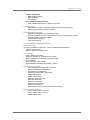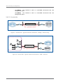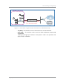
1
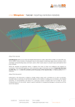
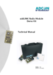
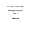
UDgateway
Installation Guide
V 5.3
Ref.: RD-IGGW050300-EN-02
The law of 11 March 1957, paragraphs 2 and 3 of article 41, only authorizes, firstly,
"copies and reproductions strictly reserved for use by copyists and not for general use
and, secondly, analyses and short quotations for the purpose of example and
illustration. Therefore, "any representation or reproduction, entire or partial, made
without the consent of the author or his representatives is illegal" (paragraph 1 of article
40).
Any such representation or reproduction, made in any manner whatever, would
therefore constitute an infringement of the law as sanctioned by articles 425 an in
accordance with the penal code.
Information contained in this document is subject to change without prior notice and
does not constitute any form of obligation on the part of OneAccess.
OneAccess and the distributors can in no case be held responsible for direct or indirect
damage of any kind incurred as a result of any error in the software or guide.
Copyright © OneAccess 2012
All rights reserved
Ref.: RD-IGGW050300-EN-21 - UDcast Technology
Contents
1. Read Me First . . . . . . . . . . . . . . . . . . . . . . . . . . 1
1.1. Who should use this manual . . . . . . . . . . . . . . . . . . . . . 1
1.2. How to use this manual . . . . . . . . . . . . . . . . . . . . . . . . . 1
1.2.1. Conventions . . . . . . . . . . . . . . . . . . . . . . . . . . . . . . . . . . . . . . . 1
1.3. General safety instructions . . . . . . . . . . . . . . . . . . . . . . . 2
2. UDgateway® Overview . . . . . . . . . . . . . . . . . . 3
2.1. Overview . . . . . . . . . . . . . . . . . . . . . . . . . . . . . . . . . . . . . 3
2.2. General characteristics . . . . . . . . . . . . . . . . . . . . . . . . . . 4
3. Before installing the UDgateway . . . . . . . . . . 7
3.1. Safety first . . . . . . . . . . . . . . . . . . . . . . . . . . . . . . . . . . . . 7
3.1.2. Safety instructions . . . . . . . . . . . . . . . . . . . . . . . . . . . . . . . . . . 7
3.2. General requirements . . . . . . . . . . . . . . . . . . . . . . . . . . . 7
3.2.1. Environment . . . . . . . . . . . . . . . . . . . . . . . . . . . . . . . . . . . . . . .
3.2.2. Airflow and cooling . . . . . . . . . . . . . . . . . . . . . . . . . . . . . . . . . .
3.2.3. Electrical power requirements . . . . . . . . . . . . . . . . . . . . . . . . .
3.2.4. Attention . . . . . . . . . . . . . . . . . . . . . . . . . . . . . . . . . . . . . . . . . .
7
8
8
8
3.3. Before installing a UDgateway® . . . . . . . . . . . . . . . . . . . 9
3.3.1. Pre-requisites . . . . . . . . . . . . . . . . . . . . . . . . . . . . . . . . . . . . . 9
3.3.1.1. Additional equipment . . . . . . . . . . . . . . . . . . . . . . . . . . . . . . . . . . . . . . . 9
3.3.1.2. Tools . . . . . . . . . . . . . . . . . . . . . . . . . . . . . . . . . . . . . . . . . . . . . . . . . . . . 9
3.3.2. Prepare network architecture . . . . . . . . . . . . . . . . . . . . . . . . . . 9
3.4. Hardware installation details . . . . . . . . . . . . . . . . . . . . . 10
3.4.1. Unpacking notes . . . . . . . . . . . . . . . . . . . . . . . . . . . . . . . . . . . 10
3.4.2. Connections . . . . . . . . . . . . . . . . . . . . . . . . . . . . . . . . . . . . . . 11
3.4.2.1. Remote site . . . . . . . . . . . . . . . . . . . . . . . . . . . . . . . . . . . . . . . . . . . . . 11
3.4.2.2. Remote multi-WAN . . . . . . . . . . . . . . . . . . . . . . . . . . . . . . . . . . . . . . . 11
3.4.2.3. Central site . . . . . . . . . . . . . . . . . . . . . . . . . . . . . . . . . . . . . . . . . . . . . . 12
4. Configuration & Customization . . . . . . . . . . 15
4.1. Preliminary . . . . . . . . . . . . . . . . . . . . . . . . . . . . . . . . . . 15
4.2. The Welcome page . . . . . . . . . . . . . . . . . . . . . . . . . . . . 16
4.3. Step-by-step configuration . . . . . . . . . . . . . . . . . . . . . . 17
4.3.1. Services available in the different configuration modes . . . . . 19
UDgateway - Installation Guide
Ref: RD-IGGW050300-EN-02
III
Contents
4.3.2. The ‘VPN and Internet access’ mode . . . . . . . . . . . . . . . . . . . 20
4.3.2.1. Step 1 - IP access configuration . . . . . . . . . . . . . . . . . . . . . . . . . . . . .
4.3.2.2. Step 2 - General network configuration . . . . . . . . . . . . . . . . . . . . . . . .
4.3.2.3. Step 3 - SMTP relay configuration . . . . . . . . . . . . . . . . . . . . . . . . . . . .
4.3.2.4. Step 4 - UDgateway peers . . . . . . . . . . . . . . . . . . . . . . . . . . . . . . . . .
4.3.2.5. Adding VPN tunnel(s) . . . . . . . . . . . . . . . . . . . . . . . . . . . . . . . . . . . . .
4.3.2.6. Adding VPN tunnel(s) - Step 1/3 - Tunnel configuration . . . . . . . . . . .
4.3.2.7. Adding VPN tunnel(s) - Step 2/3 - Key configuration . . . . . . . . . . . . .
4.3.2.8. Adding VPN tunnel(s) - Step 3/3 - Tunnel added . . . . . . . . . . . . . . . .
4.3.2.9. End of configuration - Validation . . . . . . . . . . . . . . . . . . . . . . . . . . . . .
4.3.2.10. Back to the welcome page . . . . . . . . . . . . . . . . . . . . . . . . . . . . . . . .
20
21
22
23
24
25
26
28
29
30
4.3.3.1. Step 1 - IP access configuration . . . . . . . . . . . . . . . . . . . . . . . . . . . . .
4.3.3.2. Step 2 - General network configuration . . . . . . . . . . . . . . . . . . . . . . . .
4.3.3.3. Step 3 - External management configuration . . . . . . . . . . . . . . . . . . .
4.3.3.4. Step 4 - SMTP configuration . . . . . . . . . . . . . . . . . . . . . . . . . . . . . . . .
4.3.3.5. Adding VPN tunnel(s) . . . . . . . . . . . . . . . . . . . . . . . . . . . . . . . . . . . . .
4.3.3.6. Adding VPN tunnel(s) - Step 1/4 - Tunnel configuration . . . . . . . . . . .
4.3.3.7. Adding VPN tunnel(s) - Step 2/4 - Key configuration . . . . . . . . . . . . .
4.3.3.8. Adding VPN tunnel(s) - Step 3/4 - Tunnel added . . . . . . . . . . . . . . . .
4.3.3.9. Adding VPN tunnel(s) - Step 4/4 - Tunnel added . . . . . . . . . . . . . . . .
4.3.3.10. End of configuration - Validation . . . . . . . . . . . . . . . . . . . . . . . . . . . .
4.3.3.11. Back to the welcome page . . . . . . . . . . . . . . . . . . . . . . . . . . . . . . . . .
32
33
34
35
36
37
38
40
41
42
43
4.3.4.1.
4.3.4.2.
4.3.4.3.
4.3.4.4.
4.3.4.5.
4.3.4.6.
Step 1 - IP access configuration . . . . . . . . . . . . . . . . . . . . . . . . . . . . .
Step 2 - General network configuration . . . . . . . . . . . . . . . . . . . . . . . .
Step 3 - SMTP relay configuration . . . . . . . . . . . . . . . . . . . . . . . . . . . .
Step 4 - UDgateway peers . . . . . . . . . . . . . . . . . . . . . . . . . . . . . . . . .
End of configuration - Validation . . . . . . . . . . . . . . . . . . . . . . . . . . . . .
Back to the welcome page . . . . . . . . . . . . . . . . . . . . . . . . . . . . . . . . .
45
46
47
48
49
50
4.3.5.1.
4.3.5.2.
4.3.5.3.
4.3.5.4.
Step 1 - Bridge access configuration . . . . . . . . . . . . . . . . . . . . . . . . . .
Step 2 - Domain Name Server configuration . . . . . . . . . . . . . . . . . . . .
End of configuration - Validation . . . . . . . . . . . . . . . . . . . . . . . . . . . . .
Back to the welcome page . . . . . . . . . . . . . . . . . . . . . . . . . . . . . . . . .
52
53
54
55
4.3.3. The ‘VPN only’ mode . . . . . . . . . . . . . . . . . . . . . . . . . . . . . . . 32
4.3.4. The ‘Internet only’ mode . . . . . . . . . . . . . . . . . . . . . . . . . . . . . 45
4.3.5. The ‘Bridge’ mode . . . . . . . . . . . . . . . . . . . . . . . . . . . . . . . . . 52
IV
Ref: RD-IGGW050300-EN-02
UDgateway - Installation Guide
Contents
LIST OF FIGURES
Figure 1 - Global architecture - Small Office . . . . . . . . . . . . . . . . . . . . . . . . . . . . . . 3
Figure 2 - Global architecture - Service Platform . . . . . . . . . . . . . . . . . . . . . . . . . . 4
Figure 3 - Remote Site - Typical network architecture . . . . . . . . . . . . . . . . . . . . . 11
Figure 4 - Remote Site - Multi-WAN . . . . . . . . . . . . . . . . . . . . . . . . . . . . . . . . . . . 11
Figure 5 - Central Site - Typical network architecture - Bridge - Internet only . . . 12
Figure 6 - Central Site - Typical network architecture - VPN + Internet . . . . . . . . 12
Figure 7 - Central Site - Typical network architecture - VPN Internet only . . . . . . 13
Figure 8 - The Welcome page . . . . . . . . . . . . . . . . . . . . . . . . . . . . . . . . . . . . . . . . 16
Figure 9 - Login . . . . . . . . . . . . . . . . . . . . . . . . . . . . . . . . . . . . . . . . . . . . . . . . . . . 17
Figure 10 - Welcome to the step-by-step configuration . . . . . . . . . . . . . . . . . . . . . 17
Figure 11 - Configuration Selection . . . . . . . . . . . . . . . . . . . . . . . . . . . . . . . . . . . . 18
Figure 12 - ‘VPN & Internet access’ mode: step 1/4- IP access configuration . . . 20
Figure 13 - ‘VPN & Internet access’ mode: step 2/4 - Local network
configuration . . . . . . . . . . . . . . . . . . . . . . . . . . . . . . . . . . . . . . . . . . . . . . . . . . . . . . 21
Figure 14 - ‘VPN & Internet access’ mode: step 3/4 - SMTP relay . . . . . . . . . . . . 22
Figure 15 - ‘VPN & Internet access’ mode: step 4/4 - UDstation IP address . . . . 23
Figure 16 - ‘VPN & Internet access’ mode: Adding a VPN tunnel . . . . . . . . . . . . . 24
Figure 17 - ‘VPN & Internet access’ mode: Adding a VPN tunnel - step 1/3 . . . . 25
Figure 18 - ‘VPN & Internet access’ mode: Adding a VPN tunnel - step 2/3 . . . . 26
Figure 19 - ‘VPN & Internet access’ mode: Adding a VPN tunnel - step 3/3 . . . . 28
Figure 20 - ‘VPN & Internet access’ mode: Configuration validation . . . . . . . . . . . 29
Figure 21 - ‘VPN & Internet access’ mode - Configuration validated . . . . . . . . . . 30
Figure 22 - The Welcome page after step-by-step configuration . . . . . . . . . . . . . 31
Figure 23 - ‘VPN only’ mode: step 1/4 - IP access configuration . . . . . . . . . . . . . 32
Figure 24 - ‘VPN only’ mode: step 2/4 - Local network configuration . . . . . . . . . . 33
Figure 25 - ‘VPN only’ mode: step 3/4 - NOC configuration . . . . . . . . . . . . . . . . . 34
Figure 26 - ‘VPN only’ mode: step 4/4 - SMTP relay . . . . . . . . . . . . . . . . . . . . . . . 35
Figure 27 - ‘VPN only’ mode: Adding a tunnel . . . . . . . . . . . . . . . . . . . . . . . . . . . . 36
Figure 28 - ‘VPN only’ mode: Adding a VPN tunnel - step 1/4 . . . . . . . . . . . . . . . 37
Figure 29 - ‘VPN only’ mode: Adding a VPN tunnel - step 2/4 . . . . . . . . . . . . . . . 38
Figure 30 - ‘VPN only’ mode: Adding a VPN tunnel - step 3/4 . . . . . . . . . . . . . . . 40
Figure 31 - ‘VPN only’ mode: Adding a VPN tunnel - step 4/4 . . . . . . . . . . . . . . . 41
Figure 32 - ‘VPN only’ mode: Configuration validation . . . . . . . . . . . . . . . . . . . . . 42
Figure 33 - ‘VPN only’ mode - Configuration validated . . . . . . . . . . . . . . . . . . . . . 43
Figure 34 - The Welcome page after step-by-step configuration . . . . . . . . . . . . . 44
Figure 35 - ‘Internet only’ mode: step 1/4 - IP access configuration . . . . . . . . . . . 45
Figure 36 - ‘Internet only’ mode: step 2/4 - Local network configuration . . . . . . . . 46
Figure 37 - ‘Internet only’ mode: step 3/4 - SMTP relay . . . . . . . . . . . . . . . . . . . . 47
Figure 38 - ‘VPN & Internet access’ mode: step 4/4 - UDstation IP address . . . . 48
Figure 39 - ‘Internet only’ mode - Configuration validation . . . . . . . . . . . . . . . . . . 49
Figure 40 - ‘Internet only’ mode - Configuration validated . . . . . . . . . . . . . . . . . . . 50
Figure 41 - The Welcome page after step-by-step configuration . . . . . . . . . . . . . 51
Figure 42 - ‘Bridge’ mode: step 1/2 - Bridge IP access configuration . . . . . . . . . . 52
Figure 43 - ‘Bridge’ mode: step 2/2 - DNS configuration . . . . . . . . . . . . . . . . . . . . 53
Figure 44 - ‘Bridge’ mode - Configuration validation . . . . . . . . . . . . . . . . . . . . . . . 54
Figure 45 - ‘Bridge’ mode - Configuration validated . . . . . . . . . . . . . . . . . . . . . . . 55
Figure 46 - The Welcome page after step-by-step configuration . . . . . . . . . . . . . 56
UDgateway - Installation Guide
Ref: RD-IGGW050300-EN-02
V
Contents
This page is intentionally blank
VI
Ref: RD-IGGW050300-EN-02
UDgateway - Installation Guide
1
1. Read Me First
1.1. Who should use this manual
This guide is intended for installation engineers, software support engineers and
service personnel. It is not intended for the end-user of the system.
1.2. How to use this manual
This user manual is for UDgateway®. Use the instructions in this manual to make
physical connections for the installation of the system and to configure the system
parameters.
This guide is arranged as follows:
- Chapter 1 - describes the conventions and the general safety instructions.
- Chapter 2 - for an overview of the UDgateway®
- Chapter 3 - 'Before installing the UDgateway', covers all environmental and site
requirements.
- Chapter 4 - for configuration and customization
This manual assumes that you understand the basic concepts of telecommunications
as applied to the product described, and that you are familiar with the relevant
operational network protocols involved.
1.2.1. Conventions
This user manual contains important safety instructions in form of WARNINGS and
CAUTIONS.
These instructions are enclosed in a tinted area.
WARNINGS are concerned with your safety; that is, preventing death or injury.
CAUTIONS are concerned with preventing damage to equipment.
You must read, understand, and obey all safety instructions in this manual before
proceeding with any installation or maintenance procedures, as they concern your
safety, the safety of others, and the reliability of the equipment with which you are
working.
This chapter contains important general safety instructions. Specific important safety
instructions are provided throughout this manual in the instructions where necessary.
Symbols used in the page margins to identify safety instructions conform to the
international standards.
UDgateway - Installation Guide
Ref: RD-IGGW050300-EN-02
1
Read Me
1.3. General safety instructions
Comply with all national and local safety requirements when installing this equipment.
Additionally, note the following general safety instructions:
WARNING
Do not install the equipment if it is damaged.
Notify the supplier immediately to arrange replacement equipment/parts.
WARNING
In case of fire
1. Switch off power to the equipment immediately
2. Call Fire Service
3. Use a Carbon Dioxide (CO2) or Dry Powder fire extinguisher
DO NOT USE WATER
WARNING
When moving equipment:
Do not move equipment when it is electrically connected
2
Ref: RD-IGGW050300-EN-02
UDgateway - Installation Guide
2
1
2. UDgateway® Overview
2.1. Overview
The UDgateway® is an all-in-one IP network optimizer designed for broadband
satellite, cellular networks to achieve LAN-like performance and security and to reduce
bandwidth costs.
OneAccess best-of-breed technology provides an enhanced end-user experience and
significant bandwidth savings through a combination of features such as TCP and
CIFS
acceleration,
HTTP
caching
and
pre-fetching,
QoS-based
traffic differentiation and especially bandwidth optimization through OneAccess
WANcompress technology.
WANcompress is a powerful data caching engine that provides bandwidth savings of
up to 50%. WANcompress operates at the bit stream level and is completely protocol
and application independent. Its operation is based on the redundancy normally found
in data sent over the Wide Area Network (WAN). Whenever possible, WANcompress
utilizes the data already stored in its cache rather than sending again data that has
been previously transmitted.
This mix of different technologies greatly enhances the performance of the network,
increasing its efficiency and improving the end user experience.
When there is a security requirement in the network, strong VPN security is available
to secure the connection. Traffic passed through this VPN tunnel benefits from the
same performance enhancement and bandwidth optimization features as the nonsecure traffic.
The UDgateway works with any two-way satellite system (VSAT, DVB-RCS, SCPC and
mesh), Cellular, WiMAX network (802.16d/e) or any other wireless or fixed line network
where bandwidth is expensive or limited. Networks that have high latency as well as
limited bandwidth are particularly well suited for the UDgateway.
SMALL OFFICE
UDgateway optimization on constraint link
Constraint Network
Network
UDgateway-CSO
(bandwidth limitation,
long delays, ...)
Network
UDgateway-RSO
Figure 1 - Global architecture - Small Office
UDgateway - Installation Guide
Ref: RD-IGGW050300-EN-02
3
UDgateway Overview
SERVICE PLATFORM
UDgateway optimization on constraint link
Constraint Network
Network
UDgateway-CSP
(bandwidth limitation,
long delays, ...)
Network
UDgateway-RSP
Figure 2 - Global architecture - Service Platform
The UDgateway® has 2 interfaces:
- one is connected to the Constraint Network.
- the other interface is connected to the client network with a standard Ethernet
cable.
NOTE:
Some hardware models Service Platform ready, have two (2) additional
interfaces to support multi-WAN interfaces.
2.2. General characteristics
IP routing
- Complete IPv4 stack and IP routing
- DHCP server or relay
- DHCP on WAN interface for remote installation
IP Optimization
- Two-way TCP accelerator
. ACK suppression, return path optimization
. Selective Acknowledgment (SACK) mechanism (RFC 2018)
. Large TCP window
. Ramp up & congestion avoidance
. Persistent connection
. Compression (Gzip, header)
- Redundancy elimination and compression
. IP level compression (Gzip)
. Network redundancy elimination (WANcompress)
- Application performance enhancements
. HTTP (pre-fetching, pipelining, caching)
. Web compression (option)
. DNS caching
. SMTP relay
. Windows File Exchange (SMB/CIFS) enhancement
4
Ref: RD-IGGW050300-EN-02
UDgateway - Installation Guide
UDgateway Overview
- Content distribution
. Data sending (option)
. Data reception
. File sharing
- IP performance enhancements
. QoS: weighted fair queuing - Diffserv compliant
Internet access
- NAT (Network Address Translation) with protocol & port forwarding
- Kernel based stateful inspection firewall
Link
-
-
-
-
-
Management (option)
Support for changing link IP addressing space
Support for different inbound and outbound channels (asymmetric routing)
Dynamic Quality of Service update
Link and Site redundancy
Least Cost Routing
User Bandwidth Management (option)
High Availability
To ensure operational continuity in case of hardware/software failure:
- VRRP in routed mode
- Ethernet-bypass in bridge mode
VPN security
- IPsec - ESP tunnel mode
- AES up to 256 bits or 3DES media encryption
- Split tunnelling (VPN with direct Internet access)
- NAT Traversal
- IP compression within tunnels
- High availability (hardware & software) - option
Administration features
- Zero configuration bridge mode operation
- Secured web-based management
- Configuration management
- Setup wizard with auto configuration
- SNMP/MIB support
- SNMP configuration
- Extensive diagnostic tools
- NOC access control
- WAN link monitoring
- Performance monitoring
- NTP synchronization
- Out-of-band access via serial port (external modem)
Administration features
- Secure Web interface (HTTPS)
- Secure Command Line (CLI)
- SNMP and/or KVM
UDgateway - Installation Guide
Ref: RD-IGGW050300-EN-02
5
UDgateway Overview
This page is intentionally blank
6
Ref: RD-IGGW050300-EN-02
UDgateway - Installation Guide
3
1
3. Before installing the UDgateway
3.1. Safety first
Read these safety instructions before starting any installation work. Refer also to the
general safety instructions at the beginning of this manual.
3.1.2. Safety instructions
WARNING
Before applying power to any equipment you are using or installing, look for
possible hazards such as moist floors, ungrounded power extension cables or
missing safety grounds, and locate the emergency power switch for the room in
which you are working so you can isolate power quickly if necessary.
WARNING
If an electrical accident occurs, turns off the emergency power switch for the
room in which you are working, cautiously unplug the UDgateway®'s power, and
get medical assistance for any injured person.
WARNING
Do not work alone in potentially hazardous conditions - take all precautions to
remove the hazard first.
WARNING
Keep tools away from walk areas where you and others could fall over them.
CAUTION
Keep the UDgateway® area clean and dust-free during and after installation.
3.2. General requirements
You should make sure that the following general requirements are met before
proceeding with the installation.
3.2.1. Environment
The UDgateway® must be installed in:
- a clean, dust free environment
- an area without direct sunlight, close proximity to heat sources, or high levels of
electromagnetic interference (EMI).
UDgateway - Installation Guide
Ref: RD-IGGW050300-EN-02
7
Before installing the UDgateway
3.2.2. Airflow and cooling
Provision must be made for:
- at least 10 cm free space around the UDgateway® for proper air flow
- ensuring that the UDgateway® temperature and humidity environment can be
maintained see Hardware Guide.
A sufficient air supply for the system must be provided. Be sure that no obstacles are
blocking the airflow to the air inlet
3.2.3. Electrical power requirements
- Ensure that the UDgateway® installation can be electrically bonded to a suitable
'Safety Earth'
- Ensure that the power circuit can deliver the UDgateway® needs - see Hardware
Guide
WARNING - Electrical Utility Connections
- All electrical installation work must be carried out by a qualified electrician.
- Before connection to a network the UDgateway® and associated equipment
must be wired to a suitable protective 'Safety Earth'.
- Make sure that all external units cabling are routed so as not to present a
hazard to personnel.
3.2.4. Attention
To prevent damage, do not remove the cover and avoid touching the internal
components as this could affect the guarantee of the product.
8
Ref: RD-IGGW050300-EN-02
UDgateway - Installation Guide
Before installing the UDgateway
3.3. Before installing a UDgateway®
3.3.1. Pre-requisites
Before installing the UDgateway®, check that following requirements have been met.
3.3.1.1. Additional equipment
- A computer (in order to configure your UDgateway®) and a TCP/IP connectivity and
a web browser.
- Or any computer with an OS supporting a standard TCP/IP stack and a recent web
browser should work..
3.3.1.2. Tools
No specialised tools are recommended other than tools found in a standard telecom
installation engineers toolkit.
3.3.2. Prepare network architecture
Before continuing, you should decide on the following:
- where you will be locating your equipment,
- how you will be ensuring network connectivity,
- and what will be your IP addressing.
This is a pre-requisite of installation and configuration. With this information
in hand, you will be able to proceed by following the steps described below.
UDgateway - Installation Guide
Ref: RD-IGGW050300-EN-02
9
Before installing the UDgateway
3.4. Hardware installation details
The procedure to install the UDgateway® successfully is as follows:
1. Unpack the UDgateway® and check the contents of the package
2. Interconnect the UDgateway® for configuration
For more detailed information on the hardware installation procedure, please refer
to the Hardware Guide.
3.4.1. Unpacking notes
Unpack and check the contents of the shipping packaging. Examine shipping
packaging and system parts for physical damage and shortages - report damage/
shortages immediately to the supplier. Retain damaged shipping material and
damaged parts for damage reports.
Preserve the box as well as the protective polystyrene: they are adapted to the
transport of your UDgateway®.
CAUTION
Static electricity may damage the components of your UDgateway®.
10
Ref: RD-IGGW050300-EN-02
UDgateway - Installation Guide
Before installing the UDgateway
3.4.2. Connections
All connectors are on the rear side of the UDgateway®. Connect all cables according
to the cabling plan - see Hardware Guide.
3.4.2.1. Remote site
REMOTE NETWORK
Constraint
Network
xl0
(WAN)
UDgateway
fxp0
(LAN)
xl0 = optimized interface
Figure 3 - Remote Site - Typical network architecture
- xl0 (WAN) - This interface must be connected to the Constraint Network.
- fxp0 (LAN) - This interface must be used for initial configuration (step-by-step
configuration).
Traffic going through fxp0 interface is intercepted in order to be optimized when
going through xl0 interface.
3.4.2.2. Remote multi-WAN
Constraint
Network
xl2 (WAN2)
Constraint
Network
xl1
(WAN1)
Constraint
Network
UDgateway
xl0
(WAN)
REMOTE NETWORK
fxp0
(LAN)
xl0 = optimized interface
Figure 4 - Remote Site - Multi-WAN
- xl0 (WAN) - This interface must be connected to the Constraint Network.
- fxp0 (LAN) - This interface must be used for initial configuration (step-by-step
configuration).
Traffic going through fxp0 interface is intercepted in order to be optimized when
going through xl0 interface.
UDgateway - Installation Guide
Ref: RD-IGGW050300-EN-02
11
Before installing the UDgateway
- xl1 (WAN1) - This interface is used in a multi-WAN environment with Link
Management option.
xl2 (WAN2) - This interface is used in a multi-WAN environment with Link
Management option.
3.4.2.3. Central site
UDgateway
fxp0
(LAN)
Internet
xl0
(WAN)
xl0 = optimized interface
Constraint
Network
Figure 5 - Central Site - Typical network architecture - Bridge - Internet only
CENTRAL NETWORK
Internet
fxp0
(LAN)
UDgateway
xl0
(WAN)
xl0 = optimized interface
Constraint
Network
Figure 6 - Central Site - Typical network architecture - VPN + Internet
12
Ref: RD-IGGW050300-EN-02
UDgateway - Installation Guide
Before installing the UDgateway
CENTRAL NETWORK
Internet
UDgateway
fxp0
xl0
(LAN)
(WAN)
xl0 = optimized interface
Constraint
Network
Figure 7 - Central Site - Typical network architecture - VPN Internet only
- xl0 (WAN) - This interface must be connected to the Constraint Network.
- fxp0 (LAN) - This interface must be used for initial configuration (step-by-step
configuration)
Traffic going through fxp0 interface is intercepted in order to be optimized when
going through xl0 interface.
UDgateway - Installation Guide
Ref: RD-IGGW050300-EN-02
13
Before installing the UDgateway
This page is intentionally blank
14
Ref: RD-IGGW050300-EN-02
UDgateway - Installation Guide
4
1
4. Configuration & Customization
The UDgateway® arrives pre-installed and ready for configuration. An efficiently
configuration wizard for initial parameter settings allows a quick and simple start-up of
the UDgateway®.
4.1. Preliminary
The xl0 interface must be connected to the Constraint Network.
The fxp0 interface is used for the step-by-step configuration. Its factory IP address is
172.31.3.1:3131.
In order to configure the UDgateway®, connect the UDgateway® with a machine
equipped with a Web browser (Firefox® 3.0+ or Microsoft® Internet Explorer 8.0+).
REMARK
It is recommended to connect the Administration system via the fxp0 interface
directly with a crossover cable.
IMPORTANT:
- Your web browser should access the server directly without using a proxy.
Select the appropriate settings in your web browser's settings
NOTE: For more information about other browsers, please contact Technical
Support.
UDgateway - Installation Guide
Ref: RD-IGGW050300-EN-02
15
Configuration & Customization
4.2. The Welcome page
The Welcome Page of the UDgateway® can be reached by entering the URL
https://172.31.3.1:3131 into the location bar of your web browser.
Figure 8 - The Welcome page
From the Welcome Page you can access:
- the wizard pages through the link ‘Step-by Step configuration’
- Restore a configuration
- UDgateway configuration
16
Ref: RD-IGGW050300-EN-02
UDgateway - Installation Guide
Configuration & Customization
4.3. Step-by-step configuration
You will have to supply a username and a password to access to the ‘step-by-step’
configuration.
Figure 9 - Login
- The username authorized to use the interface is: udadmin
- The udadmin user’s password is udadmin (by default).
- Click on the ‘OK’ button to access to the ‘step-by-step’ configuration.
Figure 10 - Welcome to the step-by-step configuration
UDgateway - Installation Guide
Ref: RD-IGGW050300-EN-02
17
Configuration & Customization
Click on the ‘Start’ button to begin the step-by-step configuration.
The ‘step-by-step’ configuration of the UDgateway® provides four modes. The ‘VPN
and Internet access’ mode, the ‘VPN only’ mode, the ‘Internet’ only mode and the
'Bridge' mode.
Figure 11 - Configuration Selection
- The VPN and Internet access mode - This mode enables a direct Internet access
outside the VPN, i.e. outside the encrypted tunnel.
- The VPN only mode - In this mode, all the incoming and outgoing traffic is only
going through the encrypted tunnel, i.e. via the remote UDgateway®.
- The Internet only mode - This mode enables a direct Internet access and no VPN
tunnel is created during the step-by-step configuration.
- The Bridge mode - This mode enables a direct Internet access and no VPN tunnel
is created during the step-by-step configuration. In this mode, the UDgateway acts
as a Layer-2 bridge. DHCP server is not available in this mode.
Warning:
In order to switch the UDgateway back into another mode, it is essential that the
factory settings are re-enabled.
Select the mode of configuration by clicking on the corresponding radio button and
then click on the ‘Next’ button to begin your configuration.
18
Ref: RD-IGGW050300-EN-02
UDgateway - Installation Guide
Configuration & Customization
4.3.1. Services available in the different configuration modes
Bridge
LAN services
Security
QoS
Compression
Caching
Application
optimization
Yes
DHCP (server or relay)
NAT (port or protocol
forwarding)
DNS server
Encryption(IPsec)
Statefull firewall
Web filtering (Service
Platform option)
Traffic Shaping
Packet Marking
Packet Classification
IPcomp
ZLIB (deflate)
WANcompress
No
Yes during
Step by Step
Yes
No
Yes
Yes
No
No
No
Yes
Yes
Yes
Yes
No
Yes
Yes
Yes
Yes
Yes
Yes
Yes
No
Yes
Yes
Yes for HTTP
traffic only
Yes
Yes
No
Yes
Yes
Yes
Yes
Yes
Yes
Yes
Yes
Yes
Yes
No
Yes
Yes
Yes
Yes
Yes
Yes
Yes
Yes
Yes
Yes
Yes
Yes
Yes
Yes
Yes
Yes
Yes
Yes
Yes
Yes
Yes
Yes
No
No
Yes
No
Yes
DNS cache
HTTP cache
HTTP prefetch
SMTP relay
CIFS
WEBcompress (Service
Platform option)
SNMP Monitoring
Alarms (SNMP traps)
Redundancy /
Scalability
Content
distribution
Link Management
User Bandwidth
Management
UDgateway - Installation Guide
Routed mode
without
tunnel
(tunnel-less)
DHCP client
SSH
Management
features
Routed
mode with
tunnel (VPN)
VRRP
Ethernet failover
Clustering
Yes (if a
management
IP address is
configured)
Yes (if a
management
IP address is
configured
Yes (if a
management
IP address is
configured
No
Yes
No
Yes
Yes
Service Platform option
No
No
Yes
Service Platform option
No
Yes
Yes
Service Platform option
No
Yes
Yes
Ref: RD-IGGW050300-EN-02
19
Configuration & Customization
4.3.2. The ‘VPN and Internet access’ mode
Select the ‘VPN and Internet access’ mode of configuration by clicking on the
corresponding radio button and then click on the ‘Next’ button to begin your
configuration.
4.3.2.1. Step 1 - IP access configuration
The first step of the configuration is to enter the default router IP address (e.g. IDU or
Internet gateway).
Figure 12 - ‘VPN & Internet access’ mode: step 1/4- IP access configuration
- Enter the IP address and the netmask of your IDU or Internet gateway using the
following format: a.b.c.d / netmask.
where: a.b.c.d is the subnet address and netmask (default value 24) is the number
of bits identifying the subnet (subnet length).
- Enter the upload bandwidth (in kbits/s) (default value 128).
- NAT and Firewall are enabled by default to hide and protect your LAN, uncheck
the check box to disable the NAT and Firewall.
- Enter the external IP address (xl0). Choose ‘Yes’ if you want to choose automatically
an IP address. This IP address is automatically calculated from the default IP router
address and mask. If ‘No’, specify it.
- Click on the ‘Cancel’ button if you want to abort the step-by-step configuration.
- Click on the ‘Back’ button to go back to the previous step.
- Click on the ‘Next’ button to continue your configuration.
20
Ref: RD-IGGW050300-EN-02
UDgateway - Installation Guide
Configuration & Customization
4.3.2.2. Step 2 - General network configuration
The second step of the configuration is to configure the local network.
Figure 13 - ‘VPN & Internet access’ mode: step 2/4 - Local network configuration
- Click on the ‘Cancel’ button if you want to abort the step-by-step configuration.
- Click on the ‘Back’ button to go back to the previous step.
LAN configuration
- Enter the internal IP address and the netmask of your UDgateway using the
following format: a.b.c.d / netmask
where: a.b.c.d is the subnet address and netmask (default value 24) is the number
of bits identifying the subnet (subnet length).
Configure the Name Server IP addresses
- DNS server 1: Enter the IP address of the Domain Name Server 1 that the
UDgateway will use. The DNS server 1 is the server that the UDgateway contacts
first when attempting to resolve an IP address. Your network administrator or
service provider will provide you with the IP address.
- DNS server 2 (optional): Enter the IP address of the secondary DNS server that the
UDgateway will use, if one is available. Your network administrator or service
provider will provide you with the IP address.
The secondary DNS server is the server that the router contacts if the primary
server is not available.
And then click on the ‘Next’ button to continue your configuration. If these values are
correct, the ‘SMTP configuration’ screen will appear. Otherwise, the errors are
displayed in the ‘Status window’.
UDgateway - Installation Guide
Ref: RD-IGGW050300-EN-02
21
Configuration & Customization
4.3.2.3. Step 3 - SMTP relay configuration
The next step of the configuration is to configure SMTP relay (optional).
Figure 14 - ‘VPN & Internet access’ mode: step 3/4 - SMTP relay
- Click on the ‘Cancel’ button if you want to abort the step-by-step configuration.
- Click on the ‘Back’ button to go back to the previous step.
Tick ‘Activate transparent acceleration’ if you want to enable the transparent
SMTP acceleration (instead of using smtp.udgateway.com on the mailer client).
- Enter the SMTP relay name (optional). Used to relay your mail to it’s final
destination. This information is typically given by the Service Provider.
- And then click on the ‘Next’ button to continue your configuration.
Remark: If this field is empty, no SMTP relay is used. In this case the UDgateway
SMTP agent will directly contact the final destination.
22
Ref: RD-IGGW050300-EN-02
UDgateway - Installation Guide
Configuration & Customization
4.3.2.4. Step 4 - UDgateway peers
The next step of the configuration is to configure the UDgateway peer.
The UDgateway peer can be a UDstation-Access. The UDstation-Access is a central
appliance located at the satellite hub. It is a product companion for the UDgateways
located at the end-customer sides delivering enhanced broadband Internet access
over two-way satellite system. However, it is only necessary to define an UDstation
during the UDgateway step-by-step configuration in the following cases:
1. The UDgateway accesses the Internet through a two-way satellite system. It is
not the case for a UDgateway directly connected to the Internet through a
terrestrial ISP (e.g. the UDgateway located at the Headquarter).
2. The UDgateway is configured using the "VPN and Internet access" mode or the
"Internet-only" mode.
Figure 15 - ‘VPN & Internet access’ mode: step 4/4 - UDstation IP address
- Select the radio button ‘No UDgateway peer(s)’ to disable the use of an acceleration
server. Your traffic will then be accelerated only in the VPN tunnels.
- Select the radio button ‘Yes with UDgateway peer(s) in full transparent mode’
when all the outgoing traffic from the UDgateway pass through the UDgateway
peer(s).
- Select the radio button ‘Yes with an explicit UDgateway peer’ when you must use
an explicit UDgateway peer, and enter the explicit IP address.
- Select the radio button ‘Yes with UDgateway peer(s) in auto discovery mode’
when the UDgateway must automatically detect presence of an UDgateway peer to
enable all acceleration mechanism.
UDgateway - Installation Guide
Ref: RD-IGGW050300-EN-02
23
Configuration & Customization
- Click on the ‘Cancel’ button if you want to abort the step-by-step configuration.
- Click on the ‘Back’ button to go back to the previous step.
- And then click on the ‘Next’ button to continue your configuration.
4.3.2.5. Adding VPN tunnel(s)
The next step of the configuration is to configure the VPN tunnel(s).
Figure 16 - ‘VPN & Internet access’ mode: Adding a VPN tunnel
- Click on the 'Skip tunnel creation' to skip the tunnel creation.
- Click on the ‘Cancel’ button if you want to abort the step-by-step configuration.
- Click on the ‘Back’ button to go back to the previous step.
- Click on the ‘Next’ button to start the VPN tunnel(s) configuration.
24
Ref: RD-IGGW050300-EN-02
UDgateway - Installation Guide
Configuration & Customization
4.3.2.6. Adding VPN tunnel(s) - Step 1/3 - Tunnel configuration
This step of the configuration is to configure the VPN tunnel.
Figure 17 - ‘VPN & Internet access’ mode: Adding a VPN tunnel - step 1/3
- Click on the ‘Cancel’ button if you want to abort the step-by-step configuration.
- Click on the ‘Back’ button to go back to the previous step.
- Enter a name for the tunnel (by default tunnel0).
- Enter the internal local IP address and the netmask of your tunnel. These values
are automatically completed (the values are entered during the step 2/4)
where: a.b.c.d is the subnet address and netmask (default value 24) is the number
of bits identifying the subnet (subnet length).
- Enter the external local IP address of your tunnel. This value is automatically
completed (the value is entered during the step 1/4).
- Enter the internal remote IP address and the netmask of your tunnel using the
following format: a.b.c.d / netmask. It is the IP address of the subnet reachable
through the tunnel. This step allows a route creation to reach this subnet through
the VPN.
- Enter the external remote IP address of your tunnel using the following format:
a.b.c.d It is the public address of the remote site. This step builds the tunnel
between the two external end-points.
- Enter the maximum reception capacity of the remote VPN tunnel endpoint.
- And then click on the ‘Next’ button to continue your configuration.
UDgateway - Installation Guide
Ref: RD-IGGW050300-EN-02
25
Configuration & Customization
4.3.2.7. Adding VPN tunnel(s) - Step 2/3 - Key configuration
The second step of the VPN configuration is to configure the encryption keys.
Figure 18 - ‘VPN & Internet access’ mode: Adding a VPN tunnel - step 2/3
- Click on the ‘Cancel’ button if you want to abort the step-by-step configuration.
- Click on the ‘Back’ button to go back to the previous step.
- Enter the SPI: The Security Parameter Index (SPI) is used to uniquely identify the
IPsec tunnel between two endpoints also called SA (Security Association). The
Security Parameter Index is therefore shared by both endpoints of the IPsec tunnel
and must be configured identically on both sides of the tunnel.
- Note that it can be reused for tunnels with different sources or destinations.
You can choose any number above 256.
- Choose the crypt algorithm in the following list:
. None: No crypt algorithm
. aes-cbc (128 bits): Advanced security standard algorithm. It has a block size of
256 bits.
. aes-cbc (256 bits): Advanced security standard algorithm. It has a block size of
128 bits.
. 3des-cbc (192 bits) : 3des-cbc is a symmetric secret-key block algorithm. It has
a block size of 192 bits.
. des-cbc (64 bits) : des-cbc is a symmetric secret-key block algorithm. It has a
block size of 64 bits.
26
Ref: RD-IGGW050300-EN-02
UDgateway - Installation Guide
Configuration & Customization
. blowfish-cbc (128 bits)
. cast128-cbc (128 bits)
Note:
- These algorithms are all proven to be robust (the DES algorithm having a
shorter key is more vulnerable). In doubt, we recommend using AES, both
efficient and robust against attacks.
- Of course, the same algorithm and key must be chosen by both sides of the
tunnel.
- Enter a pass phrase and click on the ‘Generate’ button to generate the crypt key.
Remark:
- As the tunnel security is based on a shared key, the same pass phrase (thus
the same crypt key) MUST be used.
- To facilitate your configuration, we provide you with a tool to generate a
64/128 bits key from a passphrase. You can either use this key generation
tool or enter a 64/128 bits key directly in hex format.
- Choose the authentication algorithm in the following list:
. None: No authentication algorithm
. hmac-md5 (128 bits): The UDgateway will use Hash Message Authentication
Code_Message Digest 5 algorithm to perform packet authentication.
. hmac-sha1 (160 bits): The UDgateway will use Hash Message Authentication
Code_Secure Hash Algorithm 1 to perform packet authentication.
Note:
- This algorithm is used to sign each packet, enabling a secure authentication
of each tunnel endpoint. In doubt, we recommend using hmac-md5. The
same algorithm and key must be chosen by both sides of the tunnel.
- Enter a pass phrase and click the ‘Generate’ button to generate the authentication
key.
Warning about passphrase:
Using a simple passphrase makes your system vulnerable against attacks.
Attacker often use dictionary attacks to discover keys generated from simple
passphrases. We recommend that you use a passphrase that is at least 20
characters long, and that includes special characters such as digits or
punctuation marks.
REMARK:
- As the tunnel security is based on a shared key, the same pass phrase (thus
the same crypt key) MUST be used.
- If you wish to use an external appliance for encryption, choose 'none' as
encryption algorithm. This will create a non-encrypted UDP tunnel between
the two UDgateways. External appliances can then be added to encrypted
this UDP connection.
- And then click on the ‘Next’ button to continue your configuration.
UDgateway - Installation Guide
Ref: RD-IGGW050300-EN-02
27
Configuration & Customization
4.3.2.8. Adding VPN tunnel(s) - Step 3/3 - Tunnel added
Now the VPN tunnel configuration is over.
Figure 19 - ‘VPN & Internet access’ mode: Adding a VPN tunnel - step 3/3
- Click on the ‘Cancel’ button if you want to abort the step-by-step configuration.
- Click on the ‘Back’ button to go back to the previous step in order to modify the
tunnel configuration.
- Click on the ‘Next’ button to continue your configuration.
- Click on the ‘Add a new tunnel’ button to add another tunnel.
28
Ref: RD-IGGW050300-EN-02
UDgateway - Installation Guide
Configuration & Customization
4.3.2.9. End of configuration - Validation
The configuration of the UDgateway® is over.
Figure 20 - ‘VPN & Internet access’ mode: Configuration validation
- Click on the ‘Cancel’ button if you want to abort the step-by-step configuration.
- Click on the ‘Back’ button to go back to the previous step.
- Click on the ‘Finish’ button to validate your changes. This will re-configure your
system and save all the parameters. All your previous configuration will be
lost.
UDgateway - Installation Guide
Ref: RD-IGGW050300-EN-02
29
Configuration & Customization
4.3.2.10. Back to the welcome page
The configuration has been validated and saved.
displayed:
The following window is now
Figure 21 - ‘VPN & Internet access’ mode - Configuration validated
Click on the ‘Back to welcome page’ link to go back to the welcome page.
30
Ref: RD-IGGW050300-EN-02
UDgateway - Installation Guide
Configuration & Customization
The UDgateway® welcome page is now displayed
Figure 22 - The Welcome page after step-by-step configuration
Now you can:
- Enter UDadmin
- Re-enter the step-by-step configuration
- Add new tunnels
- Monitoring tools
- UDgateway documentation
- the OneAccess web site. Click on the OneAccess' logo at the top-left hand side
corner of the page.
UDgateway - Installation Guide
Ref: RD-IGGW050300-EN-02
31
Configuration & Customization
4.3.3. The ‘VPN only’ mode
Select the ‘VPN only’ mode of configuration by clicking on the corresponding radio
button and then click on the ‘Start’ button to begin your configuration.
Warning:
In order to switch the UDgateway® back into another mode, it is essential that
the factory settings are re-enabled.
4.3.3.1. Step 1 - IP access configuration
The first step of the configuration is to enter the default router IP address (e.g. IDU or
Internet gateway).
Figure 23 - ‘VPN only’ mode: step 1/4 - IP access configuration
- Enter the IP address and the netmask of your IDU or Internet gateway using the
following format: a.b.c.d / netmask
where: a.b.c.d is the subnet address and netmask (default value 24) is the number
of bits identifying the subnet (subnet length).
- Enter the upload bandwidth (in kbits/s) (default value 128).
- NAT and Firewall are enabled by default to hide and protect your LAN, uncheck
the check box to disable the NAT and Firewall.
- Enter the external IP address (xl0). Choose ‘Yes’ if you want to choose automatically
an IP address. This IP address is automatically calculated from the default IP router
address and mask. If ‘No’, specify it.
- Click on the ‘Cancel’ button if you want to abort the step-by-step configuration.
- Click on the ‘Back’ button to go back to the previous step.
- Click on the ‘Next’ button to continue your configuration.
32
Ref: RD-IGGW050300-EN-02
UDgateway - Installation Guide
Configuration & Customization
4.3.3.2. Step 2 - General network configuration
The second step of the configuration is to configure the local network.
Figure 24 - ‘VPN only’ mode: step 2/4 - Local network configuration
- Click on the ‘Cancel’ button if you want to abort the step-by-step configuration.
- Click on the ‘Back’ button to go back to the previous step.
LAN configuration
- Enter the internal IP address and the netmask of your UDgateway using the
following format: a.b.c.d / netmask
where: a.b.c.d is the subnet address and netmask (default value 24) is the number
of bits identifying the subnet (subnet length).
Configure the Name Server IP addresses
- DNS server 1: Enter the IP address of the Domain Name Server 1 that the
UDgateway will use. The DNS server 1 is the server that the UDgateway contacts
first when attempting to resolve an IP address. Your network administrator or
service provider will provide you with the IP address.
- DNS server 2 (optional): Enter the IP address of the secondary DNS server that the
UDgateway will use, if one is available. Your network administrator or service
provider will provide you with the IP address.
The secondary DNS server is the server that the router contacts if the primary
server is not available.
And then click on the ‘Next’ button to continue your configuration. If these values are
correct, the ‘Network Operator Center’ screen will appear. Otherwise, the errors are
displayed in the ‘Status window’.
UDgateway - Installation Guide
Ref: RD-IGGW050300-EN-02
33
Configuration & Customization
4.3.3.3. Step 3 - External management configuration
The next step of the configuration is to configure the external management via the
Network Operator Center (optional).
Figure 25 - ‘VPN only’ mode: step 3/4 - NOC configuration
- Click on the ‘Cancel’ button if you want to abort the step-by-step configuration.
- Click on the ‘Back’ button to go back to the previous step.
- Enter the NOC subnet (optional) using the following format: a.b.c.d / netmask.
where a.b.c.d. is the IP address and netmask is the number of bits identifying the
subnet (subnet length).
- And then click on the ‘Next’ button to continue your configuration.
Remark: If this field is empty, no connection with the NOC will be allowed.
34
Ref: RD-IGGW050300-EN-02
UDgateway - Installation Guide
Configuration & Customization
4.3.3.4. Step 4 - SMTP configuration
The next step of the configuration is to configure SMTP relay (optional).
Figure 26 - ‘VPN only’ mode: step 4/4 - SMTP relay
- Click on the ‘Cancel’ button if you want to abort the step-by-step configuration.
- Click on the ‘Back’ button to go back to the previous step.
Tick ‘Activate transparent acceleration’ if you want to enable the transparent
SMTP acceleration (instead of using smtp.udgateway.com on the mailer client).
- Enter the SMTP relay name (optional). Used to relay your mail to it’s final
destination. This information is typically given by the Service Provider.
- And then click on the ‘Next’ button to continue your configuration.
Remark: If this field is empty, no SMTP relay is used. In this case the UDgateway
SMTP agent will directly contact the final destination.
UDgateway - Installation Guide
Ref: RD-IGGW050300-EN-02
35
Configuration & Customization
4.3.3.5. Adding VPN tunnel(s)
The next step of the configuration is to configure the VPN tunnel(s)
Figure 27 - ‘VPN only’ mode: Adding a tunnel
- Click on the 'Skip tunnel creation' to skip the tunnel creation.
- Click on the ‘Cancel’ button if you want to abort the step-by-step configuration.
- Click on the ‘Back’ button to go back to the previous step.
- Click on the ‘Next’ button to start the VPN tunnel(s) configuration.
36
Ref: RD-IGGW050300-EN-02
UDgateway - Installation Guide
Configuration & Customization
4.3.3.6. Adding VPN tunnel(s) - Step 1/4 - Tunnel configuration
This step of the configuration is to configure the VPN tunnel.
Figure 28 - ‘VPN only’ mode: Adding a VPN tunnel - step 1/4
- Click on the ‘Cancel’ button if you want to abort the step-by-step configuration.
- Click on the ‘Back’ button to go back to the previous step.
- Enter a name for the tunnel (by default tunnel0)
- Enter the internal local IP address and the netmask of your tunnel. These values
are automatically completed (the values are entered during the step 2/4).
where: a.b.c.d is the subnet address and netmask (default value 24) is the number
of bits identifying the subnet (subnet length).
- Enter the external local IP address of your tunnel. This value is automatically
completed (the value is entered during the step 1/4)
- Enter the internal remote IP address and the netmask of your tunnel using the
following format: a.b.c.d / netmask. It is the IP address of the subnet reachable
through the tunnel. This step allows a route creation to reach this subnet through
the VPN.
- Enter the external remote IP address of your tunnel using the following format:
a.b.c.d It is the public address of the remote site. This step builds the tunnel
between the two external end-points.
- Enter the maximum reception capacity of the remote VPN tunnel endpoint.
- And then click on the ‘Next’ button to continue your configuration.
UDgateway - Installation Guide
Ref: RD-IGGW050300-EN-02
37
Configuration & Customization
4.3.3.7. Adding VPN tunnel(s) - Step 2/4 - Key configuration
The second step of the VPN configuration is to configure the encryption keys.
Figure 29 - ‘VPN only’ mode: Adding a VPN tunnel - step 2/4
- Click on the ‘Cancel’ button if you want to abort the step-by-step configuration.
- Click on the ‘Back’ button to go back to the previous step.
- Enter the SPI: The Security Parameter Index (SPI) is used to uniquely identify the
IPsec tunnel between two endpoints also called SA (Security Association). The
Security Parameter Index is therefore shared by both endpoints of the IPsec tunnel
and must be configured identically on both sides of the tunnel.
- Note that it can be reused for tunnels with different sources or destinations.
You can choose any number above 256.
- Choose the crypt algorithm in the following list:
. None: No crypt algorithm
. aes-cbc (128 bits): Advanced security standard algorithm. It has a block size of
128 bits.
. aes-cbc (256 bits): Advanced security standard algorithm. It has a block size of
256 bits.
. 3des-cbc (192 bits) : 3des-cbc is a symmetric secret-key block algorithm. It has
a block size of 192 bits.
. des-cbc (64 bits) : des-cbc is a symmetric secret-key block algorithm. It has a
block size of 64 bits.
. blowfish-cbc (128 bits)
. cast128-cbc (128 bits)
38
Ref: RD-IGGW050300-EN-02
UDgateway - Installation Guide
Configuration & Customization
Note:
- These algorithms are all proven to be robust (the DES algorithm having a
shorter key is more vulnerable). In doubt, we recommend using AES, both
efficient and robust against attacks.
- Of course, the same algorithm and key must be chosen by both sides of the
tunnel.
- Enter a pass phrase and click on the ‘Generate’ button to generate the crypt key.
Remark:
- As the tunnel security is based on a shared key, the same pass phrase (thus
the same crypt key) MUST be used.
- To facilitate your configuration, we provide you with a tool to generate a
64/128 bits key from a passphrase. You can either use this key generation
tool or enter a 64/128 bits key directly in hex format.
- Choose the authentication algorithm in the following list:
. None: No authentication algorithm
. hmac-md5 (128 bits): The UDgateway will use Hash Message Authentication
Code_Message Digest 5 algorithm to perform packet authentication.
. hmac-sha1 (160 bits): The UDgateway will use Hash Message Authentication
Code_Secure Hash Algorithm 1 to perform packet authentication.
Note:
- This algorithm is used to sign each packet, enabling a secure authentication
of each tunnel endpoint. In doubt, we recommend using hmac-md5. The
same algorithm and key must be chosen by both sides of the tunnel.
- Enter a pass phrase and click on the ‘Generate’ button to generate the
authentication key.
Warning about passphrase:
Using a simple passphrase makes your system vulnerable against attacks.
Attacker often use dictionary attacks to discover keys generated from simple
passphrases. We recommend that you use a passphrase that is at least 20
characters long, and that includes special characters such as digits or
punctuation marks.
REMARK:
- As the tunnel security is based on a shared key, the same passphrase (thus
the same crypt key) MUST be used.
- If you wish to use an external appliance for encryption, choose 'none' as
encryption algorithm. This will create a non-encrypted UDP tunnel between
the two UDgateways. External appliances can then be added to encrypted
this UDP connection.
- And then click on the ‘Next’ button to continue your configuration.
UDgateway - Installation Guide
Ref: RD-IGGW050300-EN-02
39
Configuration & Customization
4.3.3.8. Adding VPN tunnel(s) - Step 3/4 - Tunnel added
Now the VPN tunnel configuration is over.
Figure 30 - ‘VPN only’ mode: Adding a VPN tunnel - step 3/4
- Click on the ‘Cancel’ button if you want to abort the step-by-step configuration.
- Click on the ‘Back’ button to go back to the previous step in order to modify the
tunnel configuration.
- Click on the ‘Next’ button to continue your configuration.
- Click on the ‘Add a new tunnel’ button to add another tunnel.
40
Ref: RD-IGGW050300-EN-02
UDgateway - Installation Guide
Configuration & Customization
4.3.3.9. Adding VPN tunnel(s) - Step 4/4 - Tunnel added
Now the VPN tunnel configuration is over.
Figure 31 - ‘VPN only’ mode: Adding a VPN tunnel - step 4/4
- Set the default route via a tunnel or a local gateway in ‘Set the default route via’
list in order to automatically add the default route in the Routing Table. If you
choose the local gateway, enter the IP address of the local gateway.
- Click on the ‘Cancel’ button if you want to abort the step-by-step configuration.
- Click on the ‘Back’ button to go back to the previous step in order to modify the
tunnel configuration.
- Click on the ‘Next’ button to continue your configuration.
UDgateway - Installation Guide
Ref: RD-IGGW050300-EN-02
41
Configuration & Customization
4.3.3.10. End of configuration - Validation
The configuration of the UDgateway® is over.
Figure 32 - ‘VPN only’ mode: Configuration validation
- Click on the ‘Cancel’ button if you want to abort the step-by-step configuration.
- Click on the ‘Back’ button to go back to the previous step.
- Click on the ‘Finish’ button to validate your changes. This will re-configure your
system and save all the parameters. All your previous configuration will be
lost.
42
Ref: RD-IGGW050300-EN-02
UDgateway - Installation Guide
Configuration & Customization
4.3.3.11. Back to the welcome page
The configuration has been validated and saved.
displayed:
The following window is now
Figure 33 - ‘VPN only’ mode - Configuration validated
Click on the ‘Back to welcome page’ link to go back to the welcome page.
UDgateway - Installation Guide
Ref: RD-IGGW050300-EN-02
43
Configuration & Customization
The UDgateway® welcome page is now displayed
Figure 34 - The Welcome page after step-by-step configuration
Now you can:
- Enter UDadmin
- Re-enter the step-by-step configuration
- Add new tunnels
- Monitoring tools
- UDgateway documentation
- the OneAccess web site. Click on the OneAccess logo at the top-left hand side
corner of the page.
44
Ref: RD-IGGW050300-EN-02
UDgateway - Installation Guide
Configuration & Customization
4.3.4. The ‘Internet only’ mode
Select the ‘Internet only’ mode of configuration by clicking on the corresponding radio
button and then click on the ‘Start’ button to begin your configuration.
Warning:
In order to switch the UDgateway® back into another mode, it is essential that
the factory settings are re-enabled.
4.3.4.1. Step 1 - IP access configuration
The first step of the configuration is to enter the default router IP address (e.g. IDU or
Internet gateway).
Figure 35 - ‘Internet only’ mode: step 1/4 - IP access configuration
- Enter the IP address and the netmask of your IDU or Internet gateway using the
following format: a.b.c.d / netmask
where: a.b.c.d is the subnet address and netmask (default value 24) is the number
of bits identifying the subnet (subnet length).
- Enter the upload bandwidth (in kbits/s) (default value 128).
- NAT and Firewall are enabled by default to hide and protect your LAN, uncheck
the check box to disable the NAT and Firewall.
- Enter the external IP address (xl0). Choose ‘Yes’ if you want to choose automatically
an IP address. This IP address is automatically calculated from the default IP router
address and mask. If ‘No’, specify it.
- Click on the ‘Cancel’ button if you want to abort the step-by-step configuration.
- Click on the ‘Back’ button to go back to the previous step.
- Click on the ‘Next’ button to continue your configuration.
UDgateway - Installation Guide
Ref: RD-IGGW050300-EN-02
45
Configuration & Customization
4.3.4.2. Step 2 - General network configuration
The second step of the configuration is to configure the local network.
Figure 36 - ‘Internet only’ mode: step 2/4 - Local network configuration
- Click on the ‘Cancel’ button if you want to abort the step-by-step configuration.
- Click on the ‘Back’ button to go back to the previous step.
LAN configuration
- Enter the internal IP address and the netmask of your UDgateway using the
following format: a.b.c.d / netmask.
where: a.b.c.d is the subnet address and netmask (default value 24) is the number
of bits identifying the subnet (subnet length).
Configure the Name Server IP addresses
- DNS server 1: Enter the IP address of the Domain Name Server 1 that the
UDgateway will use. The DNS server 1 is the server that the UDgateway contacts
first when attempting to resolve an IP address. Your network administrator or
service provider will provide you with the IP address.
- DNS server 2 (optional): Enter the IP address of the secondary DNS server that the
UDgateway will use, if one is available. Your network administrator or service
provider will provide you with the IP address.
The secondary DNS server is the server that the router contacts if the primary
server is not available.
And then click on the ‘Next’ button to continue your configuration. If these values are
correct, the ‘SMTP configuration’ screen will appear. Otherwise, the errors are
displayed in the ‘Status window’.
46
Ref: RD-IGGW050300-EN-02
UDgateway - Installation Guide
Configuration & Customization
4.3.4.3. Step 3 - SMTP relay configuration
The next step of the configuration is to configure SMTP relay (optional).
Figure 37 - ‘Internet only’ mode: step 3/4 - SMTP relay
- Click on the ‘Cancel’ button if you want to abort the step-by-step configuration.
- Click on the ‘Back’ button to go back to the previous step.
- Tick ‘Activate transparent acceleration’ if you want to enable the transparent
SMTP acceleration (instead of using smtp.udgateway.com on the mailer client).
- Enter the SMTP relay name (optional). Used to relay your mail to it’s final
destination. This information is typically given by the Service Provider.
- And then click on the ‘Next’ button to continue your configuration.
Remark: If this field is empty, no SMTP relay is used. In this case the UDgateway
SMTP agent will directly contact the final destination.
UDgateway - Installation Guide
Ref: RD-IGGW050300-EN-02
47
Configuration & Customization
4.3.4.4. Step 4 - UDgateway peers
The next step of the configuration is to configure the UDgateway peer.
The UDgateway peer can be a UDstation Access. The UDstation Access is a central
appliance located at the satellite hub. It is a product companion for the UDgateways
located at the end-customer sides delivering enhanced broadband Internet access
over two-way satellite system. However, it is only necessary to define a UDstation
during the UDgateway step-by-step configuration in the following cases:
1. The UDgateway accesses the Internet through a two-way satellite system. It is
not the case for a UDgateway directly connected to the Internet through a
terrestrial ISP (e.g. the UDgateway located at the Headquarter).
2. The UDgateway is configured using the "VPN and Internet access" mode or the
"Internet-only" mode.
Figure 38 - ‘VPN & Internet access’ mode: step 4/4 - UDstation IP address
- Select the radio button ‘No UDgateway peer(s)’ to disable the use of an acceleration
server. Your traffic will then be accelerated only in the VPN tunnels.
- Select the radio button ‘Yes with UDgateway peer(s) in full transparent mode’
when all the outgoing traffic from the UDgateway pass through the UDgateway
peer(s).
- Select the radio button ‘Yes with an explicit UDgateway peer’ when you must use
an explicit UDgateway peer, and enter the explicit IP address.
- Select the radio button ‘Yes with UDgateway peer(s) in auto discovery mode’
when the UDgateway must automatically detect presence of an UDgateway peer to
enable all acceleration mechanism.
48
Ref: RD-IGGW050300-EN-02
UDgateway - Installation Guide
Configuration & Customization
- Click on the ‘Cancel’ button if you want to abort the step-by-step configuration.
- Click on the ‘Back’ button to go back to the previous step.
- And then click on the ‘Next’ button to continue your configuration.
4.3.4.5. End of configuration - Validation
The configuration of the UDgateway® is over.
Figure 39 - ‘Internet only’ mode - Configuration validation
- Click on the ‘Cancel’ button if you want to abort the step-by-step configuration.
- Click on the ‘Back’ button to go back to the previous step.
- Click on the ‘Finish’ button to validate your changes. This will re-configure your
system and save all the parameters. All your previous configuration will be
lost.
UDgateway - Installation Guide
Ref: RD-IGGW050300-EN-02
49
Configuration & Customization
4.3.4.6. Back to the welcome page
The configuration has been validated and saved.
displayed:
The following window is now
Figure 40 - ‘Internet only’ mode - Configuration validated
Click on the ‘Back to welcome page’ link to go back to the welcome page.
50
Ref: RD-IGGW050300-EN-02
UDgateway - Installation Guide
Configuration & Customization
The UDgateway® welcome page is now displayed
Figure 41 - The Welcome page after step-by-step configuration
Now you can:
- Enter UDadmin
- Re-enter the step-by-step configuration
- Add new tunnels
- Monitoring tools
- UDgateway documentation
- the OneAccess web site. Click on the OneAccess logo at the top-left hand side
corner of the page.
UDgateway - Installation Guide
Ref: RD-IGGW050300-EN-02
51
Configuration & Customization
4.3.5. The ‘Bridge’ mode
Select the ‘Bridge only’ mode of configuration by clicking on the corresponding radio
button and then click on the ‘Start’ button to begin your configuration.
Warning:
In order to switch the UDgateway® back into another mode, it is essential that
the factory settings are re-enabled.
4.3.5.1. Step 1 - Bridge access configuration
The first step of the configuration is to enter the bridge IP address configuration.
Figure 42 - ‘Bridge’ mode: step 1/2 - Bridge IP access configuration
- You can define the UDgateway IP and default router using two modes:
. Yes: dynamically requested (using DHCP)
. No: static, let you specify the Management IP address/port and default router
- Upload bandwidth (in Kbits/s): Specify the upload bandwidth (default value
1024).
- Wancompress Max Peers :Specify the maximum number of accelerated peers
with Wancompress. Note that, high value may impact performances.
- Click on the ‘Cancel’ button if you want to abort the step-by-step configuration.
- Click on the ‘Back’ button to go back to the previous step.
- Click on the ‘Next’ button to continue your configuration.
52
Ref: RD-IGGW050300-EN-02
UDgateway - Installation Guide
Configuration & Customization
4.3.5.2. Step 2 - Domain Name Server configuration
The second step of the configuration is to configure the Domain Name Server.
Figure 43 - ‘Bridge’ mode: step 2/2 - DNS configuration
You can define the DNS server to use. If you use DHCP to configure IP and default
router in previous step, you can choose between dynamic (Yes) and static (No) mode.
The static mode is forced when you configure UDgateway in static mode in previous
step.
- DNS server 1: Enter the IP address of the Domain Name Server 1 that the
UDgateway will use. The DNS server 1 is the server that the UDgateway contacts
first when attempting to resolve an IP address. Your network administrator or
service provider will provide you with the IP address.
- DNS server 2 (optional): Enter the IP address of the secondary DNS server that
the UDgateway will use, if one is available. Your network administrator or service
provider will provide you with the IP address.
The secondary DNS server is the server that the router contacts if the primary
server is not available.
- Click on the ‘Cancel’ button if you want to abort the step-by-step configuration.
- Click on the ‘Back’ button to go back to the previous step.
- Click on the ‘Next’ button to continue your configuration.
UDgateway - Installation Guide
Ref: RD-IGGW050300-EN-02
53
Configuration & Customization
4.3.5.3. End of configuration - Validation
The configuration of the UDgateway® is over.
Figure 44 - ‘Bridge’ mode - Configuration validation
- Click on the ‘Cancel’ button if you want to abort the step-by-step configuration.
- Click on the ‘Back’ button to go back to the previous step.
- Click on the ‘Finish’ button to validate your changes. This will re-configure your
system and save all the parameters. All your previous configuration will be
lost.
54
Ref: RD-IGGW050300-EN-02
UDgateway - Installation Guide
Configuration & Customization
4.3.5.4. Back to the welcome page
The configuration has been validated and saved.
displayed:
The following window is now
Figure 45 - ‘Bridge’ mode - Configuration validated
Click on the ‘Back to welcome page’ link to go back to the welcome page.
UDgateway - Installation Guide
Ref: RD-IGGW050300-EN-02
55
Configuration & Customization
The UDgateway® welcome page is now displayed
Figure 46 - The Welcome page after step-by-step configuration
Now you can:
- Enter UDadmin
- Re-enter the step-by-step configuration
- Monitoring tools
- UDgateway documentation
- the OneAccess web site. Click on the OneAccess logo at the top-left hand side
corner of the page.
56
Ref: RD-IGGW050300-EN-02
UDgateway - Installation Guide
Reader's Remarks
Your comments enable improvements of the document quality; they have a significant role
when documents are updated.
If you have any comments to make, do not hesitate to tell us about them. Just give us the
page and the line references. Your comments will be carefully considered.
Please send your remarks to:
Service Support
OneAccess
BP 355
2455 route des Dolines
06906 Sophia-Antipolis Cedex
France
e-mail : [email protected]
For local offices and sales representatives, please visit our website:
www.oneaccess-net.com
Tel: +33 (0)4 93 00 16 60
Fax: +33 (0)4 93 00 16 61
B.P. 355 - 2455, route des Dolines
06906 Sophia Antipolis cedex
France