1
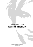
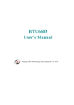
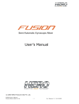
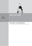
DMX booster
2 channel
10100
CONTENT
1 PICTURE .................................................................................. 3
1.1 GENERAL ....................................................................................... 3
1.2 TOP ............................................................................................. 3
2 DIMENSIONS ........................................................................... 4
3 SAFETY INFORMATION ............................................................ 5
3.1
3.2
3.3
3.4
3.5
SYMBOLS ...................................................................................... 5
PROTECTION FROM ELECTRIC SHOCK ....................................................... 6
PROTECTIONS FROM FIRE AND BURNS...................................................... 6
PROTECTION FROM INJURY .................................................................. 7
DISPOSING OF THIS PRODUCT .............................................................. 7
4 PHYSICAL INSTALLATION ....................................................... 8
4.1 UNPACKING .................................................................................... 8
4.2 LOCATION AND ORIENTATION ............................................................... 8
4.3 MOUNTING..................................................................................... 8
5 EXTERNAL CONNECTIONS...................................................... 11
5.1 AC POWER INPUT ........................................................................... 11
5.2 DMX IN AND OUTPUTS ..................................................................... 13
6 EMC AND SAFETY REQUIREMENTS ......................................... 17
7 INSTALLATION SETUP ........................................................... 18
7.1 GENERAL DESCRIPTION .................................................................... 18
7.2 TYPICAL LAYOUT ............................................................................ 18
8 SERVICE AND MAINTENANCE ................................................ 19
8.1 SAFETY PRECAUTIONS ...................................................................... 19
8.2 CLEANING.................................................................................... 19
8.3 MONITORING ................................................................................ 20
9 TROUBLESHOOTING .............................................................. 21
10 SPECIFICATIONS................................................................ 22
10.1 ELECTRICAL.................................................................................. 22
10.2 ENVIRONMENTAL ............................................................................ 22
10.3 MECHANICAL ................................................................................ 23
11 WARRANTY......................................................................... 24
11.1 APPLICATION OF WARRANTY ............................................................... 24
11.2 RMA PROCEDURE ........................................................................... 26
12 USED LIST OF ABBREVIATIONS .......................................... 27
DMX booster 2 channel
p.2/27
LUX LUMEN - Kernenergiestraat 53A - 2610 WILRIJK - BELGIUM
T: +32 3 293 35 50 – F: +32 3 293 35 44
www.lux-lumen.com
1
Picture
1.1 General
1.2 Top
DMX booster 2 channel
p.3/27
LUX LUMEN - Kernenergiestraat 53A - 2610 WILRIJK - BELGIUM
T: +32 3 293 35 50 – F: +32 3 293 35 44
www.lux-lumen.com
2
Dimensions
Please note, in dimensions given the din-rail is not included.
DMX booster 2 channel
p.4/27
LUX LUMEN - Kernenergiestraat 53A - 2610 WILRIJK - BELGIUM
T: +32 3 293 35 50 – F: +32 3 293 35 44
www.lux-lumen.com
3
Safety information
Before installing, powering up, or servicing this DMX booster it is
highly recommended that you read this manual and ensure
yourself that you completely understand its content. Observe the
safety precautions in this manual. Install and operate the DMX
booster only as described in this manual and in conformity with
local regulations. If you have any questions how to operate this
product safely please contact your point of sale.
3.1 Symbols
Following symbols are used to identify important safety
information on the product and in this manual.
DMX booster 2 channel
p.5/27
LUX LUMEN - Kernenergiestraat 53A - 2610 WILRIJK - BELGIUM
T: +32 3 293 35 50 – F: +32 3 293 35 44
www.lux-lumen.com
3.2 Protection from electric shock
This DMX booster is connected with live power so take all
precautions to prevent injuries or electrical shocks. Shut down
the power of the complete installation before carrying out any
installation or maintenance work.
Please note that all metal parts used in the enclosure where this
card is used are firmly grounded.
If any cable, seal or housing is damaged, cracked or reformed,
disconnect the power of the installation immediately.
The DMX booster is only to be used in a proper housing conform
to local regulations.
For any additional servicing, not described in this manual, please
contact your point of sale.
3.3 Protections from fire and burns
Do not operate this DMX booster if ambient temperatures, inside
its enclosure, is above 45 °C (113 °F). Please ensure yourself
that sufficient ventilation around the card is possible.
Do not modify the card in a way not described in this manual.
Never bypass the fuse or change the fuse with another type or
value as is rated in this manual.
DMX booster 2 channel
p.6/27
LUX LUMEN - Kernenergiestraat 53A - 2610 WILRIJK - BELGIUM
T: +32 3 293 35 50 – F: +32 3 293 35 44
www.lux-lumen.com
3.4 Protection from injury
Ensure yourself that all components, covers are securely
fastened. Verify that the device is firmly clicked on a standard
din-rail.
3.5 Disposing of this product
This DMX booster is manufactured in compliance with directive of
the European community: waste electrical and electronically
equipment. Please help to preserve our environment and ensure
that this product will be recycled properly at the end of its life.
DMX booster 2 channel
p.7/27
LUX LUMEN - Kernenergiestraat 53A - 2610 WILRIJK - BELGIUM
T: +32 3 293 35 50 – F: +32 3 293 35 44
www.lux-lumen.com
4
Physical installation
Thank you for selecting this DMX booster as best solution in your
setup.
Warning! Read the safety precautions in this manual before
integrating this card into your installation.
Installation must be carried out by qualified professionals only.
Assure yourself that there is sufficient and unrestricted air flow
around the DMX booster.
4.1 Unpacking
The following items are included in your package:
• DMX booster
• Carton box package
• Short form manual
4.2 Location and orientation
This DMX booster cannot be used without additional protective
housing. The housing protects the user against electrical shocks
and it is protecting the card against climatologically influences.
Please assure yourself that the cabinet which houses the DMX
booster is according to local regulations and laws of the country
of installation.
It is advised to install the card in horizontal position on the dinrail.
4.3 Mounting
The DMX booster can be mounted on a standard 35mm top hat
din-rail. A typical section of this din-rail can be found here:
Note: Use end blocking clamps if necessary in your application.
DMX booster 2 channel
p.8/27
LUX LUMEN - Kernenergiestraat 53A - 2610 WILRIJK - BELGIUM
T: +32 3 293 35 50 – F: +32 3 293 35 44
www.lux-lumen.com
The DMX booster is designed for architectural purposes in fixed
installation. To remove the DMX booster from the din-rail, gently
move the mounting clip like indicated here:
If the product is used in a situation where heavy mechanical
shocks can be expected, we advise to bolt the 2 channel DMX
booster directly on the surface. Extract the three mounting clips
as shown here. Use bolts and nuts M4 to attach the DMX booster
with the mounting clips.
DMX booster 2 channel
p.9/27
LUX LUMEN - Kernenergiestraat 53A - 2610 WILRIJK - BELGIUM
T: +32 3 293 35 50 – F: +32 3 293 35 44
www.lux-lumen.com
The three mounting holes can be found in the extracted clips
below:
In case of problems or doubts, please contact your point of sale.
DMX booster 2 channel
p.10/27
LUX LUMEN - Kernenergiestraat 53A - 2610 WILRIJK - BELGIUM
T: +32 3 293 35 50 – F: +32 3 293 35 44
www.lux-lumen.com
5
External connections
5.1 AC power input
Safety precautions
Please take all necessary precautions to prevent electrical shocks
since this product uses live power feed.
Specifications of the power input
The card operates fully functional:
• in the voltage range 220-240 Volt AC
• in the frequency range 50Hz
• Maximum power consumption is 4W
In case of doubts, please contact your point of sale.
Physical connections
The cable section of power feeding cable must be in the range
like given in the table below:
Connection technology
Conductor size : solid
Conductor size: fine-stranded
Conductor size: fine-stranded
Conductor size: fine-stranded
AWG
Strip length
Conductor entry angle
Cage Clamp®
0.08-2.5mm²
0.08-2.5mm²
0.25-1.5mm²
(with insulated ferule)
0.25-1.5mm²
(with un-insulated ferule)
28-12
5-6 mm/0.20-0.24 in
0° to PCB
Note: Cage clamp® is a trade mark of Wago contact technology.
DMX booster 2 channel
p.11/27
LUX LUMEN - Kernenergiestraat 53A - 2610 WILRIJK - BELGIUM
T: +32 3 293 35 50 – F: +32 3 293 35 44
www.lux-lumen.com
Location of power input-clamps
The power input can be found below:
Fuse located on board
A fuse to protect the card from overload or short circuit can be
found beside the input clamp.
Only replace the fuse with 125mA rated, T type.
DMX booster 2 channel
p.12/27
LUX LUMEN - Kernenergiestraat 53A - 2610 WILRIJK - BELGIUM
T: +32 3 293 35 50 – F: +32 3 293 35 44
www.lux-lumen.com
5.2 DMX in and outputs
Precautions
Never connect other devices as a DMX transmitter or receiver to
the input and outputs.
In case of doubts, please contact your point of sale.
Specifications DMX input and outputs
The DMX booster has one DMX input and two “active” DMX
outputs. These DMX outputs are amplified and completely
galvanic isolated from any other in/output.
Each output can feed max 32 fixtures.
The end of a DMX line should preferably be terminated with a
120 ohm resistor between + and – of the DMX line. For more
information see ‘termination of the DMX Signal’
The green LED’s lights up when data signal is high. It doesn’t
validate if the data is a valid DMX signal.
DMX booster 2 channel
p.13/27
LUX LUMEN - Kernenergiestraat 53A - 2610 WILRIJK - BELGIUM
T: +32 3 293 35 50 – F: +32 3 293 35 44
www.lux-lumen.com
Location of the DMX input-clamps
The DMX input can be found below:
Location of the DMX output-clamps
The DMX outputs can be found below:
Physical DMX connections
The connection of the DMX wiring is made with Cage Clamps®
The cable section of DMX feeding cable must be in the range like
given in the table below:
Connection technology
Conductor size: solid
Conductor size: fine-stranded
Conductor size: fine-stranded
Conductor size: fine-stranded
AWG
Strip length
Conductor entry angle
Cage Clamp®
0.08-2.5 mm²
0.08-2.5 mm²
0.25-1.5 mm²
(with insulated ferule)
0.25-1.5 mm²
(with un-insulated ferule)
28-12
5-6 mm/0.20-0.24 in
0° to PCB
Note: Cage clamp® is a trade mark of Wago contact technology
DMX booster 2 channel
p.14/27
LUX LUMEN - Kernenergiestraat 53A - 2610 WILRIJK - BELGIUM
T: +32 3 293 35 50 – F: +32 3 293 35 44
www.lux-lumen.com
Specifications cabling
The use of Cat.5 or Cat.6 cable is conformal the DMX 2004 by
USITT in fixed installations. For more detailed information:
www.usitt.org
The benefits are:
•
•
•
•
•
•
Low cost of cabling
Low cost of connectors
Worldwide availability
Fast application on site
Very well known by electrical contractors
Reliable connections
Suitable cable for transmission of the DMX-signal
Name of Shielded
cable
or not
shielded
CAT 5E
Not
UTP
CAT 5E
FTP or
STP
Yes
CAT 6
UTP
Not
CAT 6
FTP or
STP
Yes
Remarks
regarding
shielding
No ground
connection at
output
terminals
Connection of
shielding to PE
clamp of output
terminals
No ground
connection at
output
terminals
Connection of
shielding to PE
clamp of output
terminals
Max run
length
250 m
Termination
above run
length (see 7.1)
100 m
250 m
100 m
250 m
100 m
250 m
100 m
DMX booster 2 channel
p.15/27
LUX LUMEN - Kernenergiestraat 53A - 2610 WILRIJK - BELGIUM
T: +32 3 293 35 50 – F: +32 3 293 35 44
www.lux-lumen.com
Pin layout of UTP to XLR connectors
XLR pin 1 wired to UTP contacts 7 and 8. UTP wire color usually
brown and brown/white for shielding.
XLR pin 2 wired to UTP contact 2. UTP wire color usually orange
for data negative connection.
XLR pin 3 wired to UTP contact 1. UTP wire color usually
orange/white for data positive connection.
Termination of the DMX signal
To avoid disturbance of the DMX-signal it is recommended to
terminate the DMX-line at the last open ‘through’ connector at
each physical DMX-line. This is done with an ‘end plug’. This end
plug consists of a 0.25 watt resistor of 120 ohm between pins 1
and 2 of the connector.
Typical schematic of the end plug can be found below:
DMX booster 2 channel
p.16/27
LUX LUMEN - Kernenergiestraat 53A - 2610 WILRIJK - BELGIUM
T: +32 3 293 35 50 – F: +32 3 293 35 44
www.lux-lumen.com
6
EMC and safety requirements
The DMX booster is fully compliant to the LVD and EMC directive
of the European council, if used in a properly designed setup.
EMC requirements of the power supply:
The DMX booster is only intended to be used in lighting
applications, and as such, the complete assembly of led unit and
power supply needs to be fully compliant with the harmonized
standards.
Immunity according to:
• EN 61547:2009 (General EMC immunity requirements
lighting eq.)
• EN 61000-4-1:2006 (General immunity testing techniques)
• EN 61000-4-2:2008 (ESD immunity test)
• EN 61000-4-3:2006 + A1:2007 (Radiated immunity test)
• EN 61000-4-4:2004 (Fast transients and burst immunity)
• EN 61000-4-5:2005 (Surge immunity test)
• EN 61000-4-6:2008 (Conducted immunity test)
• EN 61000-4-8:1993 (Magnetic field immunity test)
• EN 61000-4-11:2004 (Voltage variations immunity test)
• EN 61000-6-1:2005 (Generic standards for immunity)
Emission according to:
• EN 61000-3-2:2005+A1:2008+A2:2009 (Harmonics
emission test<16A)
• EN 61000-3-3:2008 (Flicker+ voltage changes limits< 16A)
• EN 55015:2006+A2:2009 (Conducted + radiated emission
lighting equipment)
To achieve this compliance, a proper power supply must be
supplied. In case of doubts, contact your point of sale.
LVD requirements of the power supply:
The DMX booster is only intended to be used in lighting
applications, and as such, the complete assembly of led unit and
power supply needs to be fully compliant with following
harmonized standards:
• EN 60598: general requirements of lighting equipment.
DMX booster 2 channel
p.17/27
LUX LUMEN - Kernenergiestraat 53A - 2610 WILRIJK - BELGIUM
T: +32 3 293 35 50 – F: +32 3 293 35 44
www.lux-lumen.com
7
Installation setup
7.1 General description
The DMX booster is typically intended to distribute a DMX signal
over two different cables. There are two “active” outputs. These
DMX outputs are amplified and completely galvanic isolated from
any other in/output. Each output can feed max 32 fixtures.
7.2 Typical layout
The wiring scheme below shows a typical layout when using the
two DMX outputs.
DMX booster 2 channel
p.18/27
LUX LUMEN - Kernenergiestraat 53A - 2610 WILRIJK - BELGIUM
T: +32 3 293 35 50 – F: +32 3 293 35 44
www.lux-lumen.com
8
Service and maintenance
8.1 Safety precautions
Read carefully the safety information in this manual. Lock out
the power on the entire system and allow all electronic devices
to discharge, and cool down, before executing any service or
maintenance.
8.2 Cleaning
DMX booster itself
Extensive dirt and particle build-up degrades performance and
may cause overheating. This can result in damaged board and
power supply’s. Damage by inadequate cleaning or maintenance
is not covered by the product warranty.
Never use solvents to clean the outer housing of the card.
Never use water or wet cloth.
Enclosure in which the DMX booster is integrated
Best is to use compressed air to remove dust or soft cloth to
remove the dust in the cabinet. When using compressed air, care
must be taken not to damage the fans in the enclosure. Never
use solvents to clean the outer housing of the enclosure.
DMX booster 2 channel
p.19/27
LUX LUMEN - Kernenergiestraat 53A - 2610 WILRIJK - BELGIUM
T: +32 3 293 35 50 – F: +32 3 293 35 44
www.lux-lumen.com
8.3 Monitoring
three led’s are located between the DMX IN connectors and the
DMX out connectors.
LED1 : red led - indicates power
LED2 : green led – lights up when (+) signal is high
LED3 : green led – lights up when (-) signal is high
Note: The green leds do not validate if the data is a valid DMX
signal.
DMX booster 2 channel
p.20/27
LUX LUMEN - Kernenergiestraat 53A - 2610 WILRIJK - BELGIUM
T: +32 3 293 35 50 – F: +32 3 293 35 44
www.lux-lumen.com
9
Troubleshooting
Color of
led
RED
Status
of led
On
Off
GREEN 1
On
Off
GREEN 2
On
Off
Problem
Action
Power is applied to
the card.
No power is
applied to the card
Check the status of
the green leds.
Check the fuse and
the incoming power
supply
Check the other
green LED
Check the DMX IN
signal
The (+) data
signal is high
There is no data
on the (+)
connection of DMX
IN
The (-) data signal
is high
There is no data
on the (-)
connection of DMX
IN
Check the other
green LED
Check the DMX IN
signal
DMX booster 2 channel
p.21/27
LUX LUMEN - Kernenergiestraat 53A - 2610 WILRIJK - BELGIUM
T: +32 3 293 35 50 – F: +32 3 293 35 44
www.lux-lumen.com
10
Specifications
10.1
Electrical
Inputs
•
•
•
•
•
220-240 volt AC
Maximum 4 watt power consumption.
Power input on Cage clamp® for easy connection
DMX input on Cage clamp® for easy connection
Status led’s for DMX and power input
Outputs
• 2 independent ‘active’ DMX outputs
• DMX outputs are amplified
• DMX outputs are completely galvanic isolated from any
other in/output
• Each output can feed max 32 fixtures
• DMX outputs on Cage clamp® for easy connection
• The end of a DMX line should preferably be terminated with
a 120ohm resistor between + and – of the DMX line.
10.2
•
•
•
•
•
Environmental
IP rating: IP 20
Humidity: 30% to 95%
Ta (max) : +40 °C (104 °F)
Ta (min): -15 °C (+5 °F)
Tc (max): +55 °C (131 °F)
DMX booster 2 channel
p.22/27
LUX LUMEN - Kernenergiestraat 53A - 2610 WILRIJK - BELGIUM
T: +32 3 293 35 50 – F: +32 3 293 35 44
www.lux-lumen.com
10.3
Mechanical
Physical dimensions of the card below:
Dimensions DMX booster
Dimensions packaging
Weight DMX booster
Weight packaging
88x 90 x 58
230 x 230 x 130
375
500
DMX booster 2 channel
mm
mm
gr
gr
p.23/27
LUX LUMEN - Kernenergiestraat 53A - 2610 WILRIJK - BELGIUM
T: +32 3 293 35 50 – F: +32 3 293 35 44
www.lux-lumen.com
11
Warranty
11.1
Application of warranty
Warranty period
Warranty service is valid for one year from the date of purchase
by the consumer, as evidenced by invoice date given out by your
point of sale.
Warranty service
Service under warranty can only be done by Lux Lumen.
Coördinaties:
Lux Lumen
Kernenergiestraat 53 A
2610 Wilrijk
Belgium
Any cost of secure transportation of the product to and from Lux
Lumen service department, will be borne by the customer.
Limitations
Lux Lumen will not warrant the following:
• Periodic check-ups, maintenance and repair or replacement
of parts due to normal wear and tear.
• Consumables
• Any software
• Defects caused by modifications carried out without Lux
Lumen’s approval.
• Damage resulting from the fact that a product is not
conforming to country specific standards or specifications in
another country that the country of purchase.
Costs incurred by Lux Lumen’s service center in making any
adoptions or modifications of a product necessary for country
specific technical or safety standards or specifications, or any
other cost to adjust the product as a result of any specifications
which have changed since the delivery of the product.
DMX booster 2 channel
p.24/27
LUX LUMEN - Kernenergiestraat 53A - 2610 WILRIJK - BELGIUM
T: +32 3 293 35 50 – F: +32 3 293 35 44
www.lux-lumen.com
Warranty service is excluded if damage or defects have
been caused by:
Improper use, extensive use, handling or operation of the
product as referred to in the user manual or operator manual
and/or relevant user documents, including without limitation,
incorrect storage, dropping, excessive shocks, corrosions, dirt,
water, or sand damage, if the product is not rated to be used in
severe conditions, indicated by its IP and IK degree, mentioned
in the product specifications in this manual.
Repairs, modifications or cleaning carried out by a non Lux
Lumen service centre.
Use of spare parts, software or consumables, which are not
compatible with the product.
Connecting the product to equipment not intended to be used
with this product.
Defects caused by improper condition of the power supply
network.
Inadequate packaging of the product when returning it under the
RMA procedure.
Accidents or disasters or any cause beyond the control of Lux
Lumen, including but not limited to lightning, water, fire, public
disturbances, improper ventilation, and acts of god.
Others
It is the responsibility of the customer to backup and save any
software files and programs before repair and to restore the
same after such repair.
This warranty does not affect the consumer’s statutory rights
under applicable national legislation in force, nor the consumer’s
rights against the retailer arising from the sales/purchase
contract. In the absence of applicable national legislation, this
warranty will be the consumer’s sole and exclusive remedy, and
Lux Lumen cannot be liable for any incidental or consequential
damages for breach of any express or implied warranty of this
product.
For full details of the warranty offered on this product, please
contact Lux Lumen’s service center.
DMX booster 2 channel
p.25/27
LUX LUMEN - Kernenergiestraat 53A - 2610 WILRIJK - BELGIUM
T: +32 3 293 35 50 – F: +32 3 293 35 44
www.lux-lumen.com
11.2
RMA procedure
To send material back to Lux Lumen, you need a RMA (Return
Material Authorization) document that you will receive from Lux
Lumen.
Without the RMA document, we cannot accept the material.
The procedure to obtain a RMA:
Step 1:
Customer contacts Lux Lumen about warranty, defects if
material has to be returned.
Step 2:
Lux Lumen sends the customer a filled out RMA document (using
a unique RMA number)
Step 3:
Customer sends material (include a copy of the RMA document
with the material)
Step 4:
Lux Lumen evaluates the problem, and informs the client if
repair is done under warranty, or makes an offer to the client for
repair.
Step 5:
The procedure related to lux lumen quality procedures, according
ISO 9001 is started up.
DMX booster 2 channel
p.26/27
LUX LUMEN - Kernenergiestraat 53A - 2610 WILRIJK - BELGIUM
T: +32 3 293 35 50 – F: +32 3 293 35 44
www.lux-lumen.com
12
Used list of abbreviations
•
•
•
•
•
•
•
•
•
•
•
•
DMX: digital multiplexed data signal to according to USITT
PCB: printed circuit board
PWM: Pulse width modulation
CAT 5: category 5 cable
CAT 6: category 6 cable
Uf: Forward voltage of the LED junction
AC: Alternating current
DC: Direct current
°F: Temperature in degrees Fahrenheit
°C: Temperature in degrees Celsius
din-rail: rail used in electrical installation according to
‘Deutsche Industry Norm’ specifications
LED: Light Emitting Diode
DMX booster 2 channel
p.27/27
LUX LUMEN - Kernenergiestraat 53A - 2610 WILRIJK - BELGIUM
T: +32 3 293 35 50 – F: +32 3 293 35 44
www.lux-lumen.com