1
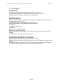
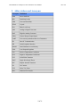
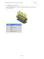
Embedded Now ComExpress Carrier Hardware User Manual
!
Rev 0.20
!
!
Piconium
!
“Pico” sized Comm Express Carrier
Industrial Grade, wide voltage range
Card - User Manual
!
1! of 21
!
Embedded Now ComExpress Carrier Hardware User Manual
Revision History
Date
Revision
Description
12/01/2014
0.10
Initial Revision
01/20/2015
0.2
Second Revision
!
2! of 21
!
Rev 0.20
Embedded Now ComExpress Carrier Hardware User Manual
!
Table of Contents
Table of Contents
3
Description 4
Abbreviations and Acronyms 5
Block Diagram
6
Functional Description
7
Com Express Interfaces
7
Power and Reset
8
HDMI Video 8
LVDS Video 8
USB 9
Unused Interfaces
11
Power 11
Low Voltage Regulation
11
5V Regulation 11
3.3V Regulation
12
VLCD Regulation
12
Connectors 14
Com Express A/B Connector 14
Power Connector (J1) 14
Reset Connector (CN1)
15
HDMI Connector (J12)
16
LVDS Connector
17
Backlight Connector (J8)
18
USB 2.0 Type A Connector (P2, P3, P4, P5, P6, P8) 19
USB 3.0 SS Connector (P7) 20
LEDs 21
Switches and Shunts 21
Shunts 21
!
!
!
3! of 21
!
Rev 0.20
Embedded Now ComExpress Carrier Hardware User Manual
Rev 0.20
1. Description
Processor!
Available as a COMX Type 10 Carrier card only -OR- with a choice of… !
Congatec MA3 module with 3rd Generation Intel Atom or Celeron Processor!
Single or Multi Core Processor, Various speeds, 1GB-8GB Ram!
!
Specifications!
Very Low Power (5-7W max) 10-28V single power supply via locking industrial grade connector!
Industrial temp range (-40 to 100C)!
Very Small, low profile form factor (approx. 130mm x 55mm)!
LVDS display interface – single 24bit channel with LED control!
6X USB 2.0!
1X USB 3.0 (Super Speed)!
1 HDMI port!
Wifi (b,g,n) (via WiFi USB “dongle”)!
Bluetooth 4.0 (via BT USB “dongle”)!
Accessories available: LVDS displays & cables with touch panel, power supply, BT & WiFi
“dongles”!
Customizations are available for your specific needs!
!
Operating System & Software!
Designed for the Linux® Operating System (will work with others)!
Available: USB 3.0 Flash Drive Preloaded with Ubuntu® 14.04 LTS Desktop, LUbuntu, Ubuntu
Server &!
Chromium Embedded Framework (CEF) for web based software development & deployment!
Also available: BIOS programming tools boot drive (USB 2.0 thumb drive)!
!
!
!
!
4! of 21
!
!
Embedded Now ComExpress Carrier Hardware User Manual
2. Abbreviations and Acronyms
Acronym Definition
POR
Power On Reset
BSL
BootStrap Loader
USB
Universal Serial Bus
XTAL
Crystal
PLL
Phase Lock Loop
ADC
Analog to Digital Convertor
DAC
Digital to Analog Convertor
GPIO
General Purpose Input/Output
UART
Universal Asynchronous Receiver/Transmitter
I2C
Inter-IC Communication
SPI
Serial Peripheral Interface
SRAM
Static Random Access Memory
LDO
Low Dropout Regulator
PTC
Positive Temperature Coefficient
NTC
Negative Temperature Coefficient
FET
Feild Effect Transistor
SPST
Single Pole Single Throw
BJT
Bipolar Junction Transistor
NC
No Connect
PTZ
Point, Tilt, Zoom
WFT
Wireless File Transfer
!
5! of 21
!
Rev 0.20
Embedded Now ComExpress Carrier Hardware User Manual
3. Block Diagram
Below is the block diagram of the ComExpress Carrier Board.
!
System Block Diagram
6! of 21
!
Rev 0.20
Embedded Now ComExpress Carrier Hardware User Manual
Rev 0.20
4. Functional Description
The primary function of the Piconium Carrier Board is to mount a type 10 ComExpress
Module from any vendor. However, this board has been designed to interface with the
Congatec MA3 type 10 module.
4.1. Com Express Interfaces
The physical interface to the Com Express module supports the A/B connector only and a
sub set of the electrical interfaces. It is not in the scope of this document to define the
Com Express electro-mechanical interface. More detailed information can be found in the
Com Express Specification from PICMG.
!
!
!
Figure 2: Connector A/B Overview
The next sections will briefly describe the main interfaces supported on the Com Express
Carrier Board.
7! of 21
!
Embedded Now ComExpress Carrier Hardware User Manual
Rev 0.20
4.1.1. Power and Reset
Power Button, Reset & GND are provided to the connector. A connector on the carrier
card provides the PWR_BTN and SYS_RESET inputs to the Com Express Board.
!
PWR & Reset Signals
Signal
Description
PWR_BTN_N
When asserted low, wakes up the system from S5 State.
SYS_RESET_N When asserted low, the Com Express module resets and reboots
!
4.1.2. HDMI Video
HDMI is supported.
!
4.1.3. LVDS Video
The Com Express A/B connector supports up to 2 LVDS video interfaces.
!
!
Com Express Signals: LVDS
8! of 21
!
Embedded Now ComExpress Carrier Hardware User Manual
Rev 0.20
!
The carrier board routes only channel “A” to a 20 pin header for interface to a monitor
via a custom cable. All differential pairs are protected from ESD using EMI4182
common mode filter with low capacitance (0.8pf) ESD protection.
!
!
High Speed Filter and Transient Protection
4.1.4. USB
The Com Express specification supports eight USB ports along with over current
detection for each port pair. Piconium supports 6 USB 2.0 ports and 1 USB 3.0 port
(with 2.0 backwards compatibility)
!
!
Com Express Signals: USB
9! of 21
!
Embedded Now ComExpress Carrier Hardware User Manual
Rev 0.20
!
!
USB Port Allocation
Port
Description
0
Routed to P7 for USB2.0 compatibility for the USB 3.0 port
1
Routed to P2 and right angle Type A connector
2
Routed to P8 and right angle Type A connector
3
Routed to P3 and right angle Type A connector
4
Routed to P4 and right angle Type A connector
5
Routed to P5 and right angle Type A connector
6
Routed to P6 and right angle Type A connector
!
The power to each connector is enabled using a TPS2042 power switch which is always
on. The TPS2042 supports two switches and current monitors. Below shows the
configuration of the TPS2042 for ports 0 and 1. This is duplicated for the other port pairs.
!
5V
3.3V
C57
1UF
R44
10.0K
U9
2
3
4
1
IN1
EN1
EN2
GND
OUT1
OUT2
OC1
OC2
TPS2042
L10
7
6
VUSB0
VUSB1
L11
8
5
USB_OC_0_1_N
C58
1UF
C59
1UF
C60
1UF
C61
1UF
!
!
!
USB Power Switch and Current Monitoring
The TPS2042 also monitors the current draw on VBUSx and asserts the respective OC
output which is an open drain output, pulled up and connected to the OC_N inputs to the
Com Express module.
!
4.1.4.1. Port 1
Port 1 is connected to a Type A connector and is filter and protected using an EMI4182
device.
! of 21
10
!
Embedded Now ComExpress Carrier Hardware User Manual
Rev 0.20
!
P2
U8
10
9
USB1+
USB1-
7
6
OUT_1+
OUT_1OUT_2+
OUT_2-
IN_1+
IN_1IN_2+
IN_2GND
5
1
2
4
5
VUSB1
B_USB1+
B_USB1-
3
!
!
VCC
DD+
GND
1
2
3
4
6
EMI4182
!
1
2
3
4
TY PE A RA
USB Port 1
4.1.5. Unused Interfaces
The carrier card does not utilize the following ports on the A/B connector.
• Low Pin Count (LPC)
• SPI
• SMB
• I2C
• PCI Express
• SATA
• Ethernet
!
!
5. Power
The input power comes from an external 10-28V supply and enters the system at J1. The
input voltage is regulated down to 3.3V, 5V and V_LCD which can be configured as a 5V
or 3.3V output via a shunt. Likewise, the input voltage is regulated up or down to
provide 12V for the LCD display. Each supply has an LED associated with it that
illuminates when the supply is on. Refer to Section 0.
5.1. Low Voltage Regulation
5.1.1. 5V Regulation
To generate the 5V, a Texas Instrument TPS54140 Buck switch with adjustable output is
used. The TPS54140 can supply up to 1.5A of current and provides over current
protection.
!
The TPS54140 is configured to regulate at 5V via the VSENSE voltage which is set by
R6 and R9. R5 and R57 also provide an under voltage protection and will only allow the
supply to regulate if the input voltage is greater than 9.18V.
!
! of !21
11
Embedded Now ComExpress Carrier Hardware User Manual
Rev 0.20
3.3V
R4
332
12V
U1
3
R5
10.0K
4
5
8
R7
76.8K
UVLO = 9.18V
9
11
VIN
PWRGD
EN
BOOT
SS/TR
RT/CLK
COMP
GND
TPAD
PH
6
PWR_OK
C3
1
.1UF
VSENSE
68UH
D4
SS16
7
4
5V
L1
10
1
C1
.1UF
R6
52.3K
C100
47UF
C4
47UF
C5
.1UF
2
2
C2
10UF
TPS54140
R57
3.74K
C6
.01UF
R8
150K
C7
6.8pF
R9
10.0K
C8
2700PF
!
5V Regulation
!
PWR_OK is routed to the Com Express module indicating all power supplies are valid.
5.1.2. 3.3V Regulation
To generate the 3.3V, a Texas Instrument TPS54140 Buck switch with adjustable output
is used. The TPS54140 can supply up to 1.5A of current and provides over current
protection.
!
The TPS54140 is configured to regulate at 3.3V via the VSENSE voltage which is set by
R14 and R59. R10 and R58 also provide an under voltage protection and will only allow
the supply to regulate if the input voltage is greater than 9.18V.
!
12V
U2
C9
.1UF
R10
10.0K
4
5
8
R12
76.8K
9
11
VIN
PWRGD
EN
BOOT
SS/TR
RT/CLK
COMP
GND
TPAD
PH
6
C11
1
10
VSENSE
3.3V
L2
.1UF
47uH
1
C10
10UF
3
D6
SS16
7
R14
31.6K
C101
47UF
C12
47UF
C13
.1UF
2
2
TPS54140
R58
3.74K
C14
.01UF
R13
150K
C15
6.8pF
R59
10.0K
C16
2700PF
!
!
!
3.3V Regulator
The PWRGD signal, being an open-drain output is connected to PWR_OK signal of the
5V regulator.
5.1.3. VLCD Regulation
The V_LCD rail for the LVDS monitor is also derived using a Texas Instrument
TPS54140 Buck switch with adjustable output. The TPS54140 can supply up to 1.5A of
current and provides over current protection.
!
The TPS54140 is configured to regulate at 3.3V or 5V via the VSENSE voltage which is
set by R64, R65 and R56. The Shunt J11 adds R64 to the circuit and if not installed,
adjusts the output to be 5V and if installed, creates a parallel resistance between R64 and
R65 (31.6K) and adjusts the output to be 3.3V.
! of 21
12
!
Embedded Now ComExpress Carrier Hardware User Manual
12V
U18
3
C103
.1UF
4
5
8
3.3V
R61
10.0K
J10
V_LCD_EN
2
P2
P1
R62
76.8K
PWRGD
EN
BOOT
SS/TR
RT/CLK
COMP
GND
TPAD
PH
6
C104
1
10
VSENSE
C108
.01UF
R63
150K
C109
6.8pF
V_LCD
L21
.1UF
68UH
D11
SS16
7
C105
47UF
TPS54140
1
SILK: DISPLAY PWR ON
9
11
VIN
1
2
C102
10UF
C106
47UF
C107
.1UF
2
!
!
Rev 0.20
C110
2700PF
R64
80.6K
R65
52.3K
J11
2
P2
P1
1
SILK: VLCD
SELECT
OUT: 5V
IN: 3.3V
R66
10.0K
!
!
V_LCD Regulator
The Enable input is pulled up to 3.3V and if the shunt J10 is not installed, the regulator is
enabled. If J10 is installed, then software can control the enable via the V_LCD_ON
signal from the Com Express Module.
!
! of 21
13
!
Embedded Now ComExpress Carrier Hardware User Manual
Rev 0.20
!
6. Connectors
6.1. Com Express A/B Connector
Refer to the Com Express Specification for the pin-out of this connectors.
6.2. Power Connector (J1)
J1 is a Molex 39-30-1020 1x2 Right Angle Mini-Fit Jr. connector that provides power to
enter onto the board.
!
Pin
Description
1
12V In
2
Ground
!
! of 21
14
!
Embedded Now ComExpress Carrier Hardware User Manual
Rev 0.20
6.3. Reset Connector (CN1)
CN1 is a Samtec TSW-105-07-G-D 2x5 2.54mm header that provides connectivity to
external peripherals.
!
!
Pin
Description
1
GND
2
PWR_BTN_R
3
GND
4
SYS_RESET_N
!
! of 21
15
!
Embedded Now ComExpress Carrier Hardware User Manual
Rev 0.20
6.4. HDMI Connector (J12)
J12 is a JAE Electronics DP1RD20JQ1R400 Right Angle Display Port Connector that
provides connectivity to external Display Port Monitors
Pin
Description
1
D2+
2
D2 Shield
3
D2-
4
D1+
5
D1 Shield
6
D1-
7
D0+
8
D0 Shield
9
D0-
10
CLK+
11
CLK Shield
12
CLK-
13
CE Remote
14
NC
15
DDC_CLK
16
DDC_DATA
17
GND
18
5V
19
HP_DETECT
! of 21
16
!
Embedded Now ComExpress Carrier Hardware User Manual
Rev 0.20
6.5. LVDS Connector
J7 is a Hirose df14-20p-1.25 1x20 header that provides connectivity to external LVDS
Displays.
Pin
Description
1
V_LCD
2
V_LCD
3
GND
4
NC
5
LVDS0-
6
LVDS0-
7
GND
8
LVDS1-
9
LVDS1+
10
GND
11
LVDS2-
12
LVDS2+
13
GND
14
LVDS_CLK-
15
LVDS_CLK+
16
GND
17
LVDS3-
18
LVDS3+
19
GND
20
6/8 bit select (jumper)
! of 21
17
!
Embedded Now ComExpress Carrier Hardware User Manual
6.6. Backlight Connector (J8)
CN1 is a Hirose B5B-PH-SM4-TB(LF)(SN) 1x5 2.54mm header that provides
connectivity to the backlight power of LVDS Monitors.
Pin
Description
1
12V
2
LVDS_BKLT_EN
3
GND
4
LVDS_BKLT_CTRL
5
5V
!
! of 21
18
!
Rev 0.20
Embedded Now ComExpress Carrier Hardware User Manual
6.7. USB 2.0 Type A Connector (P2, P3, P4, P5, P6, P8)
P2 is an Amp 292336-1 Vertical Mount Type A USB connector that provides
connectivity to external peripherals.
!
Pin
Description
1
VUSB1
2
USB1-
3
USB1+
4
GND
!
! of 21
19
!
Rev 0.20
Embedded Now ComExpress Carrier Hardware User Manual
Rev 0.20
6.8. USB 3.0 SS Connector (P7)
P7 is an Amp 292336-1 Horizontal Mount Type A USB connector that provides
connectivity to external peripherals.
!
Pin
Description
USB
1
VUSB1
2.0 and 3.0
2
USB1-
2.0
3
USB1+
2.0
4
GND
2.0
5
RX-
3.0
6
RX+
3.0
7
GND
3.0
8
TX-
3.0
9
TX+
3.0
!
! of 21
20
!
Embedded Now ComExpress Carrier Hardware User Manual
7. LEDs
There are LEDs on the board as described below;
LED
Signal
Description
D2
5V
On when 5V is valid
D3
3.3V
On when 3.3V is valid
D12
V_LCD
On when the 5V to the LVDS is enabled
8. Switches and Shunts
8.1. Shunts
There are four shunts on the board. They are defined below.
!
Shunt
State
Description
J10
In
Allows software control of the V_LCD
Enable
J10
Out
V_LCD is forced on
J11
In
V_LCD = 3.3V
J11
Out
V_LCD = 5V
!
! of 21
21
!
Rev 0.20