1
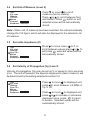
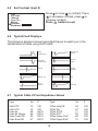
4.1
Testing a cable
Having followed the set up procedures in the preceding sections, a typical
display showing impedance anomalies is shown below. Further
examples are shown in section 4.6.
Vp=72% Z=100Ω
64m
129m
180m
The vertical cursor line is moved left or right along the line of the trace by
pressing and buttons to determine the distance to the event. Position
the cursor at the beginning of the event and read off the distance at the
bottom left corner.
On the fault display shown above a low impedance fault occurs at 64
meters shown by a negative spike, and a high impedance at 129 meters.
The open end of the cable is shown as a large positive spike, this is used
to determine the end of the cable run and the overall length of the cable
being 180 meters.
4.2
Selecting Range Scales
The Pro400 has 9 range scales covering the range of 20 ft to
6,000 ft.
To select a range scale, or scan the cable run, press and hold
down the Select button and press
to decrease range, press
to increase range.
4.3
Single shot and Continuous Scanning Modes
When the Pro400 is first switched on, it is set to “Single Shot”
mode.
In this mode the Pro400 only fires a pulse into the cable under
test when either the and buttons or button is pressed.
12