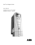
1
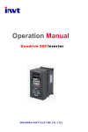
IPE200 Engineering drive inverter
Detailed function description
it may cause motor overheat or inverter fault
Figure 6-9
Function
Name
Code
P4.09
V/F curve setting diagram.
V/F slip
compensation
Description
0.00~10.00Hz
Setting
Factory
Range
Setting
0.00~10.00
0.0Hz
The motor’s slip changes with the load torque, which results in the variance of motor speed.
The inverter’s output frequency can be adjusted automatically through slip compensation
according to the load torque. Therefore the change of speed due to the load change can be
reduced. The value of compensated slip is dependent on the motor’s rated slip which can be
calculated as: P4.09=fb-n*p/60. Where fb is motor rated frequency (P2.01), n is motor rated
speed (P2.02), and p is pole pairs of motor.
Function
Name
Code
Description
Setting
Factory
Range
Setting
0~2
1
0: Disabled
P4.10
AVR function
1: Enabled all the time
2: Disabled during
deceleration
AVR (Auto Voltage Regulation) function ensures the output voltage of inverter stable no matter
how the DC bus voltage changes. During deceleration, if AVR function is disabled, the
deceleration time will be short but the current will be big. If AVR function is enabled all the time,
the deceleration time will be long but the current will be small.
Function
Name
Code
P4.11
Description
Auto energy
0: Disabled
saving selection
1: Enabled
Setting
Factory
Range
Setting
0~1
0
When P4.11 is set to be 1, while there is a light load, it will reduce the inverter output voltage
and saves energy.
.54.