1
RMS compact
User Manual
RMS compact
(Version 1.0.9)
2
RMS compact
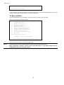
Conventions Used In This Guide
This guide uses these conventions:
Bold italic print, as shown in this example, indicates field names, menu items, or values in the RMS compact software agent.
Bold print, as shown in this example, indicates filenames, directories, or items that you must type exactly as they appear.
Italic print words or letters in braces { } indicate values that you must supply. For example: {drive}:\setup
Italic print words or letters in brackets < > indicate keys to press. If two keys are separated by a + plus symbol, then the first key should be
pressed and held down while pressing the second key. For example: <alt+enter>.
Note:
Warning! :
Notes contrast from the text to emphasise their importance.
These messages alert you to specific procedures or practices; serious consequences may result including injury if you
disregard them.
Copyright 2003
Knürr AG
Unauthorised reproduction prohibited.
3
RMS compact
Table of Contents
Conventions Used In This Guide ............................................................... 3
Introduction .................................................................................................... 6
Types of Sensors....................................................................................... 6
RMS compact Package ................................................................................ 7
RMS compact Package Contents............................................................. 7
The RMS compact Unit.............................................................................. 7
Software....................................................................................................10
Configuration Cable .................................................................................10
Power Supply ...........................................................................................10
System Requirements ................................................................................11
Installation.....................................................................................................12
Fitting into the 19” rack.............................................................................12
Using the 1U frontplate adapter............................................................12
Without the 1U adapter .........................................................................13
Cable Management..................................................................................14
Preparing to Configure.............................................................................14
Verify RMS compact Operation ...........................................................15
Configuration ...............................................................................................16
Serial Port Configuration..........................................................................16
Main Menu..............................................................................................16
Network Configuration Group ...............................................................16
Net Access Configuration.....................................................................17
Telnet Configuration..............................................................................17
Pass-thru port parameters ....................................................................18
NMS Configuration ................................................................................18
Trap Host Configuration........................................................................19
Temperature and Humidity Configuration............................................19
Temperature Configuration...................................................................20
Humidity Configuration..........................................................................21
Centigrade or Fahrenheit?....................................................................21
Contact Closure (digital input) Configuration.......................................21
Shutdown Targets .................................................................................24
Reset to Default Settings......................................................................24
Set Output and Boolean Settings.........................................................25
Setting up Boolean Logic Values.........................................................26
To Save and Exit ...................................................................................29
Configuration using an Internet Browser.................................................30
Main Status Page ..................................................................................30
Input Status............................................................................................31
Output Status .........................................................................................32
Network Setup .......................................................................................32
Configuration using the RMS compact Programmer Software .............34
System Requirements .............................................................................34
Installation.................................................................................................34
Configuration ............................................................................................35
Configure Unit Menu.................................................................................37
The Show Configuration screen...........................................................37
4
RMS compact
The ‘File’ Menu ......................................................................................41
Setup Menu............................................................................................43
Configure Actions..................................................................................43
The Control Menu..................................................................................48
Appendix A: Using the Temperature Hysteresis Function.................50
How it Works.............................................................................................50
Setup.........................................................................................................50
Enable Temperature monitoring & set thresholds ..............................50
Setup logic.............................................................................................51
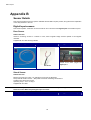
Appendix B ...................................................................................................53
Sensor Details ..........................................................................................53
Digital Input sensors .............................................................................53
Analogue Input Sensors .......................................................................55
Appendix C: Serial/TFTP Firmware Upgrades......................................57
Install.........................................................................................................57
Run SerialTFTP........................................................................................57
TFTP Upgrade .........................................................................................58
Serial Upgrade..........................................................................................59
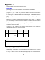
Appendix C ...................................................................................................60
Reference.................................................................................................60
Communities..........................................................................................60
IP Addresses ........................................................................................60
Subnetting and Subnet Masks..............................................................60
Gateways ...............................................................................................61
Troubleshooting .......................................................................................61
Appendix D: Configuring the NMS...........................................................63
General Network Management Stations ..............................................63
RMS Compact Common Setup Error Checklist....................................64
Serial Communications Setup .................................................................64
Network Communication..........................................................................64
SNMP communication..............................................................................64
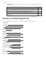
Placing a Technical Support Call.............................................................65
Reference Worksheet .................................................................................67
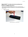
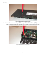
Appendix E: The Waste Electrical and Electronic Equipment (WEEE) Regulations
5
68
RMS compact
Introduction
RMS compact is a hardware adapter that enables monitoring of the micro-environment of the rack. This
Ethernet-compatible network adapter uses networking protocols, such as SNMP, TCP/IP, Web and Telnet to
bring the non-networked components of the rack within view and control of the system manager.
RMS compact remotely monitors up to eight digital inputs and includes two analogue ports for temperature and
humidity sensing. It also includes three power switching outputs. It polls the monitored devices for status
information and this information is then ‘translated’ into SNMP and provided back to the network management
station via the in-built Ethernet link.
The output capabilities of the RMS compact allows it to take actions given a pre-defined set of input conditions
– e.g. if a fan failure is reported, and the temperature rises above a certain level, the an additional set of fans
could be activated.
RMS compact is a highly compact and cost effective solution to the difficulties posed by the rack environment,
where space is at a premium. What’s more, it deploys off the shelf without the need for specialist installation
skills and after the initial set-up, the password protected web browser interface can be used for remote
configuration.
Types of Sensors
A number of different types of sensors can be monitored by the RMS compact, some examples are:
•
Temperature
•
Humidity
•
Smoke
•
Shock
•
Door Contact
Further sensors available on request
Note :
Maximum cable length for each type of sensor is 50 metres
Note:
It is not possible to use the vowel mutations “Umlaut” and "ß" for any of the text fields in the RMS
compact at present
6
RMS compact
RMS compact Package
The standard RMS compact package contains an RMS-Compact Unit with supporting hardware and software.
RMS compact Package Contents
The components of your package are:
£
£
£
£
RMS compact Unit
RMS compact Support software CD-ROM (containing MIB file Viewer/Programmer, manual etc.)
Power Supply
Configuration Cable (DB9 Female to Female Null Modem)
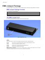
The RMS compact Unit
The following photographs show the RMS compact front and rear panels:
Manual reset
Switch
Figure 1 RMS compact Front
LED’s
There are four LED’s on the front of the RMS Compact, their function is described below:
Status:
Green when in normal operating mode, Red if an internal fault has occured
Alarm:
Yellow if an input alarm condition is present
RS232:
Flashes green when data passing through RS232 port
TCP/IP:
Flashes green indicating network traffic.
Manual Reset Switch:
The unit can be manually reset by pushing a narrow object such as a small
screwdriver through the hole in the front of the unit, to activate the reset switch.
7
RMS compact
RS232
Connection
Configuration DIP
switch
Digital Alarm Inputs (see
expanded drawing)
12volts DC in
10baseT ethernet
Network
connection
Temperature
& Humidity 1
Temperature
& Humidity 2
Relay
Outputs
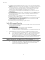
Figure 2 RMS compact Rear panel
The rear of the RMS compact unit houses all connection points to inputs and output, as follows
12 volts DC In: Power in.
Warning! : USE POWER SUPPLY SUPPLIED WITH THE RMS COMPACT UNIT ONLY. FAILURE TO DO SO MAY BE
DANGEROUS AND WILL AFFECT YOUR WARRANTY RIGHTS.
Configuration DIP switch - To set the device into configuration mode, and to configure for serial firmware
upgrade.
10baseT Ethernet Network connection: For connection to a 10Mb/s ethernet LAN via UTP/STP
cable. The Network interface operates in half-duplex mode..
RS232 Connection: For serial configuration and serial firmware upgrades.
Temperature & Humidity 1: For connection of Temperature & humidity sensor.
Temperature & Humidity 2: For connection of Temperature & humidity sensor.
Digital Alarm Inputs: For connection of digital (i.e. voltage free), contact alarms. The picture below
illustrates how each digital input should be wired:
Warning! : CONNECT
ONLY VOLT FREE ALARM SIGNALS TO THE DIGITAL ALARM INPUTS OF THE RMS
COMPACT. CONNECTION OF ANYTHING OTHER THAN A VOLT FREE SIGNAL MAY DAMAGE THE
RMS COMPACT AND INVALIDATE YOUR PRODUCT WARRANTY
8
RMS compact
Input 1
Input 2
Input 3
Input 5
Input 6
Input 7
Input 4
Input 8
Figure 3: Digital Input Connections
Signal+
+12volts
Signal -
C o mmo n
Figure 4: Input Pin configuration
As we can see, there are 8 possible digital inputs available. These inputs are split into of 4 poles per
input, as follows:
Note:
Signal + :
Volt free contact connection
Signal - :
The common connection for voltage free contact
Common:
The common connection for a +12volt input
+12Volts:
Input Connection for an alarm at +12volts
The maximum load for the 12v output should not exceed 200mA – should this load be exceeded, then
an internal fuse will be blown. This fuse should only be replaced by a qualified electrician.
Relay Output Connections: For connection of external devices (such as fans etc)
The output relay connections are wired as follows:
9
RMS compact
Output
1
Com
NO
OUT 1
Output
2
Com
NO
OUT 2
Output
3
Com
NO
OUT 3
Figure 5: Output Relay Pin configuration
There are three physical relay outputs on the RMS Compact, all of which are wired in a Normally Open (NO)
configuration. These relays are capable of switching mains voltage at a current of up to 5A (230 VAC, 30VDC)
each.
Software
The software shipped with RMS compact is on CD-ROM. This CD-ROM contains the RMS compact MIB file,
the Viewer/Programmer software, along with this manual and any other relevant tools (such as Terraterm Pro
terminal emulation software and SerialTFTP firmware upgrade program). The MIB will need to be compiled into
your NMS database.
Configuration Cable
Your package contains a configuration cable (DB9 female-to-female Null Modem). Use this cable to connect the
RMS compact serial port and a dumb terminal or PC for configuration. When you configure the RMS compact,
be sure to set the DIPswitch to the proper setting see the Installation section in this manual. Any dumb terminal
or terminal emulation package, such as Microsoft Windows 95/98/NT HyperTerminal will work fine, providing it is
capable of running at up to 38400 baud.
Power Supply
The type of power supply offered is:
Power Supply Type
Input
Output
Plug Top
230 VAC, 50 Hz
12 VDC, 500mA
10
RMS compact
System Requirements
RMS compact requires a terminal or terminal program for configuration and a network connection with an NMS
or supplied Viewer/Programmer software for operation. The following is a description of all required
components and a list of the most widely used NMSs.
•
The components of your standard RMS compact package
•
Connection to an 10baseT Ethernet network
•
An SNMP-based management station
•
A dumb terminal or a PC with an emulation package capable of running at 38400 baud, to configure the
RMS compact SNMP Agent, e.g. Windows 95/98/NT HyperTerminal or supplied Terraterm software
•
An RS232 communication port on your PC or terminal
•
Network identification values for the RMS compact :
IP Address
Net Mask
IP Addresses for the NMS
Definitions of Communities
IP Address of the Gateway/Router on the same segment as the RMS compact
11
RMS compact
Installation
Fitting into the 19” rack
There are two ways of mounting RMS compact into a 19” rack system. These are explained below:
Using the 1U frontplate adapter
•
Unpack the RMS compact from its packaging.
•
Attach the 1U frontplate to the RMS compact as follows:
1.
Remove the 3 fixing screws from the front of the top of the RMS compact
2.
Slide the 19” adapter plate over the front of the unit, and replace the fixing screws. The diagram below
shows the position of these screws:
Fixing Screw
Fixing Screw
Fixing Screw
Figure 6: Mounting the 19" Adapter frontplate
and bolt into the 19” racking. The following diagrams shows how this is done:
Fixing Bolts
Figure 7: RMS Compact with 19" front plate, rack mounted (Front View)
12
RMS compact
Figure 8: RMS Compact with 19" front plate, rack mounted (Top View)
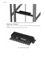
Without the 1U adapter
It is also possible to mount the RMS compact in a rack without the 1U frontplate, using the supplied adapter
bracket.
The following figure shows how the mounting plate is fixed to the unit:
Figure 9: Attaching the mounting plate
13
RMS compact
The figures below show an example of where the RMS compact could be mounted
Mounting
screws
RMS compact
Figure 10: RMS compact mounted without 19" Front plate
Cable Management
The RMS compact has a cable management tray attached to the casing of the unit. This enables the user to
route and attach cables to prevent any accidental disconnection.
Preparing to Configure
For configuration, connect the RMS compact temporarily to a PC with a terminal emulation package such as
Terraterm, (contained on the RMS compact Cdrom), or to a dumb terminal capable of communicating at 38400
baud. The following steps guide you in connecting the RMS compact to the network and UPS.
1.
2.
4.
Adjust the DIPswitches on the RMS compact for Configuration. Switch 1 down (ON); switch 2 up (OFF).
Temporarily, connect the RMS compact adapter to a dumb terminal or to a PC with the terminal emulation
package.
a) Using the supplied configuration cable, connect one end of the cable into a dedicated RS-232 serial
port on the configuration PC.
b) Connect the other end to serial port 1 on the RMS compact.
Configure the communications settings.
Use the following settings to configure the dumb terminal or PC.
Baud rate à
9600
Flow Control à
None
Data bits à
8
Handshaking à
None
Stop bit
à
1
Terminal Type:à
ANSI (VT100)
Parity
à
None
Local Echo
à
Off
14
RMS compact
5. Press OK if you have the Windows Communications screen or accept your communication settings in
the terminal emulation package. The terminal is now configured to communicate with the RMS compact
adapter.
6. Connect the power supply with the 12VDC connector to the RMS compact adapter’s power input.
Connect the other end of the power supply input cable to a UPS supplied power socket or power
distribution unit. The adapter should display the introductory screen on your terminal.
7. You are now ready to configure the RMS compact adapter. Refer to the Configuration section for a
detailed discussion.
8. Once configuration is complete, turn DIPswitch 1 on the RMS compact from the DOWN (ON) position
to the UP (OFF) position.
9. Disconnect the configuration cable from the RMS compact adapter and the dumb terminal or PC.
Store this cable for future use.
10. Disconnect the RMS compact adapter from the PC or terminal and from the power supply.
11. DIPswitch 1 is still set to OFF (UP) position.
12. Place the RMS compact in the rack, and connect up all required sensors to the relevant connectors on
the RMS compact, along with any reauired output connections and Network cable (see the RM S
compact Package section of this manual for details)
13. Connect the RMS compact to the Ethernet cable.
14. Re-insert the power jack into the RMS compact ’s power connection.
Verify RMS compact Operation
15. After you complete all configuration settings and connect the RMS compact to the network, check that
the STATUS led is lit, and is GREEN
LED Status After Power Up
II.
Note:
A.
The STATUS led should be permanently ON and in a GREEN state.
B.
The TCP/IP led should start flashing intermittently.
C.
If any input alarm conditions have been previously set, then the ALARM led may be YELLOW
PING the RMS compact. Issue a PING command from the NMS (Network Management Station).
A.
If you do not get a response, check the RMS compact ’s network connection and IP address.
B.
Test the adapter with an NMS. Perform a “GET” and a “SET.” (assuming an NMS is to be
used, if this is not the case, then test for communication by using the RMS compact
Viewer/Programmer software (see the section of the manual called Configuration using the
RM S compact Programmer Software in this manual for instructions on how to do this)
The RMS compact MIB file, (contained on the accompanying CD-ROM), must be compiled into the
NMS before this can be done – instructions on how to do this will vary depending upon the type of
NMS being used, please refer to the NMS documentation for further information
C.
If the GET or SET commands fail, check the RMS compact access controls. The manager
must have read permission to execute a GET command successfully and read/write
permission to execute a SET command successfully.
15
RMS compact
Configuration
Serial Port Configuration
You are now ready to configure the RMS compact to work on your network. RMS compact is temporarily
connected to a PC with a terminal emulation package or to a dumb terminal.
Note:
Refer to the Installation section for the proper setting of the hardware adapter, and for terminal
program settings prior to configuring the device.
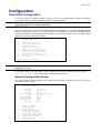
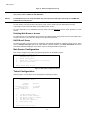
Main Menu
From the main menu you can select to change the Network Configuration, i.e. enter the IP address, Gateway
address, and MIB system group; you can set the access controls of SNMP communities; set the NMS and trap
receiver configuration; configure temperature and humidity; configure contact closure setup, set output settings
and save the new values and exit the program.
Knuerr RMS compact version X.X.X
Embedded Agent Setup
1.
2.
3.
4.
5.
6.
7.
8.
9.
10.
Network Configuration
Net Access Configuration
NMS Configuration
Trap Host Configuration
Temp & Humidity Configuration
Contact Closure Configuration
Shutdown Targets Configuration
Restore Default Settings
Set Output and Boolean Settings
Exit Setup
Enter choice (ESC to exit):
Figure 11 Main Menu
Note:
When configuration is complete, changes must be saved to take effect, by selecting ‘Exit Setup’
followed by ‘2’ to save.
To select any option on the Main Menu, enter the number of the option you want at the Choose at the Enter
choice (ESC to exit): prompt. The program displays the desired screen.
Network Configuration Group
To set the IP address, Gateway address, subnet mask, and other system configurations, type 1 at the prompt.
The following screen displays:
Knuerr RMS compact version X.X.X
Embedded Agent Setup
IP Address:
Net Mask:
Gateway:
Agent Location:
HTTP:
HTTP username:
HTTP password:
Card Host Name:
Boot Type:
1.
2.
3.
4.
5.
6.
7.
8.
9.
10.
1.1.222.222
255.255.0.0
0.0.0.0
<No sysLocation Set>
enabled
admin
knuerr
RMSC
DHCP
Change IP Address
Change Net Mask
Change Gateway
Change Agent Location
Change HTTP User Name
Change HTTP User Password
[en/dis]able HTTP daemon
Change Card Host Name
Change Boot Type
Exit Network Setup
16
RMS compact
Figure 12 Network Configuration Group
Note:
The minimum requirement to operate RMS compact is to set the IP address (or have DHCP/BootP set
one), and to enter an NMS into the NMS table.
Note:
Invalid Addresses in the Trap Host table may cause problems with traps not being sent, SNMP SET
commands not working etc.
To enter values, enter the number of the option, Press <enter>. Enter your new value after the prompt
If you want to return to the Main Menu, press 10 and press <enter>.
For more information on IP addresses and net masks, see the Reference section of the Appendix C in this
manual.
Enabling Web Browser Access
To enable access for configuration and monitoring via a Web browser using HTTP, the user must enable HTTP
access in this menu. They must also assign a user name and password.
DHCP/BootP Setup
To enable the RMS compact to have an IP address automatically assigned by a DHCP or BootP server, select
option 9 Change boot type and set for either DHCP or BootP operation. The Card Host Name field, is the
information that will be displayed on the DHCP server to identify the RMS compact unit.
Net Access Configuration
This section configures the Telnet and passthrough options for the RMS compact :
Knuerr RMS compact version X.X.X
Embedded Agent Setup
1.
2.
3.
Telnet Configuration
Serial Port 1 Configuration for pass-thru
Exit Net Access Setup
Enter choice (ESC to exit):
Figure 13 Net Access Configuration Group
Telnet Configuration
Selecting option 1 in the above menu will display the following sub-menu:
Knuerr RMS compact version X.X.X
Embedded Agent Setup
Telnet:
password:
inactivity timeout:
passthru port:
passthru terminator:
1.
2.
3.
4.
5.
6.
enabled
30 seconds
disabled
0
[en/dis] Telnet Access
Set Telnet Access Password
Set Telnet Inactivity Timeout
Set Pass-thru Port
Set Pass-thru Terminator
Exit Telnet Setup
Enter choice (ESC to exit):
17
RMS compact
Figure 14 Telnet Configuration screen
This menu is used to enable/disable Telnet access to the RMS Compact, also to set a Telnet username and
password. The RMS compact also has the ability to make a ‘passthrough’ connection to a device attached to the
serial port – this section sets the serial port to be used for this purpose.
Pass-thru port parameters
Option 2 in the Net Access menu deals with the actual configuration details of the serial port when used in
passthrough mode (see above). Selecting option 2, will display the following menu:
Knuerr RMS compact version X.X.X
Embedded Agent Setup
Current Settings for Port 1
Baud Rate:
Parity:
Data Size:
Stop Bits:
1.
2.
3.
4.
5.
9600
NONE
8 bits
1 bits
Set baud rate
Set parity
Set data size
Set stop bits
Exit Serial Port Setup
Enter choice (ESC to exit):
Figure 15 Serial Port pass-thru Configuration screen
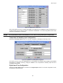
NMS Configuration
The following screen displays a column of four Network Manager IP addresses with their access permission
and SNMP community string. Use this screen to specify which managers have access to the RMS compact
agent, the community names, and what type of access the IP managers have–read only or read and write.
Entry
1
2
3
4
IP Address
001.001.020.023
000.000.000.000
000.000.000.000
000.000.000.000
Community String
public
Access
rw
ro
ro
ro
Select Table entry to change (ESC to exit):
Figure 16 NMS Configuration
To set access for an NMS:
Enter the number of the column from 1 through 4 and return, then select the parameter that requires configuring
from the list as below
Note:
All required RMS compact Viewer/Programmer Stations and NMS IP addresses MUST be defined in
the NMS configuration table, also, it is advised that the community string be entered in lower case.
IP Address:
Community String:
Access:
1.
2.
3.
1.1.14.17
public
READ/WRITE
Change NMS IP Address
Change NMS Community String
Change NMS Access Privileges
18
RMS compact
4.
Exit NMS Setup
Enter choice (ESC to exit):
Figure 17 NMS Parameters
The Community String setting is public by default , this parameter works like a type of snmp password. This
parameter can be changed, but this change must also be reflected at the NMS and RMS compact
Viewer/Programmer.
The top of the screen reflects your changes:
To return to the Main Menu, type 4 and press <enter>.
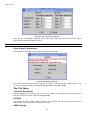
Trap Host Configuration
Use this screen to determine which IP managers receive TRAPs (alarm messages) from your RMS compact.
This screen permits you to send TRAPs about your UPS to up to ten IP addresses (managers). To access the
trap setting screen, type 4 from the Main Menu. The following screen displays:
Entry
1
2
3
4
5
6
7
8
9
10
IP Address
Community String
001.001.020.23
public
001.001.014.015
public
000.000.000.000
000.000.000.000
000.000.000.000
000.000.000.000
000.000.000.000
000.000.000.000
000.000.000.000
000.000.000.000
Trap Ctl Auth
yes
yes
yes
yes
no
no
no
no
no
no
no
no
no
no
no
no
no
no
no
no
Select Table entry to change (ESC to exit):
Figure 18 Trap Receivers
To set TRAPs, at the prompt type the entry number to be edited and <enter>. The following screen will be
displayed:
Knuerr RMS compact version X.X.X
Embedded Agent Setup
IP Address:
1.1.124.124
Community String:
public
Flag 1:
YES
Flag 2:
YES
1.
2.
3.
4.
5.
Change Trap Host IP Address
Change Trap Host Community String
Change Control Trap Flag
Change Enable Trap Flag
Exit Trap Host Setup
Enter choice (ESC to exit):
Figure 19 Trap Host information
Enter the number for the parameter that is to be edited and <enter>.
The Control Trap flag, enables/disables sending of traps to this address. The Enable trap flag, enables trap
authentication for this NMS address.
The top of the screen reflects your changes:
To return to the Main Menu, type 5 at the prompt and press <enter>.
Note:
Please ensure that only valid Trap Receiver IP addresses are entered into the Trap Host
table within the RMS compact.Adding invalid trap receiver addresses may result in the RMS
compact being unreachable across the network
Temperature and Humidity Configuration
19
RMS compact
To set Temperature & Humidity thresholds and other values, select 5 at the main menu (please note that an
additional optional temperature & Humidity sensor is required for this). The following menu should be displayed:
Knuerr RMS compact version X.X.X
Embedded Agent Setup
1.
2.
3.
4.
5.
6.
Change Temperature 1 Settings
Change Humidity 1 Settings
Change Temperature 2 Settings
Change Humidity 2 Settings
Select Centigrade or Fahrenheit
Exit Enviromental Inputs Setup
Enter choice (ESC to exit):
Figure 20 Temperature and Humidity Configuration
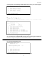
Temperature Configuration
Option 1 in this menu sets the temperature parameters for temperature sensor 1, and displays the following
menu:
Knuerr RMS compact version X.X.X
Embedded Agent Setup
Temp Monitor Enabled:
Temp Name:
Temp Offset:
Temperature units:
1.
2.
3.
4.
5.
6.
7.
8.
9.
YES
Temperature 1
0.0
Centigrade
Change Temperature Monitoring Flag
Change Temperature Name
Change Temperature Offset
Change Temperature Limits
Change Temperature OFF to ON Traps
Change Temperature OFF to ON Traps
Change Temperature ON to OFF Traps
Change Temperature ON to OFF Traps
Exit Temperature Setup
Setup
Repeat Timers
Setup
Repeat Timers
Enter choice (ESC to exit):
Figure 21 Temperature parameter Configuration
This menu enables the user to ENABLE/DISABLE temperature monitoring, change the TEXT descriptor of the
alarm, set OFFSETS, select THRESHOLD limits (this includes limits for the warning traps to indicate that a
temperature is nearing its threshold), and also to set TRAP REPEAT TIMERS.
Note:
The Minimum Setting for a Trap Repeat Timer is 30 seconds.
This option should display the following menu:
Knuerr RMS compact version X.X.X
Embedded Agent Setup
Temperature
Temperature
Temperature
Temperature
1.
2.
3.
4.
5.
Lower
Lower
Upper
Upper
Control
Warning
Warning
Control
Change Lower Control
Change Lower Warning
Change Upper Warning
Change Upper Control
Exit Limits Setup
Limit:
Limit:
Limit:
Limit:
-20.0
-20.0
35.0
40.0
Limit
Limit
Limit
Limit
Enter choice (ESC to exit):
Figure 22 Temperature threshold Limits Configuration
20
RMS compact
Also, in the Temperature Parameter screen, the user is able to enable traps for off to on transitions and on to off
transitions, as well as setting timers for repeat traps if required.
The same options are available for Temperature 2 (the second temperature sensor port).
Note:
If a Temperature only sensor is being used (i.e. no humidity), then the humidity monitoring must me
MANUALLY DISABLED, in order to prevent an error reading from the RMS Compact.
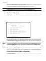
Humidity Configuration
Selecting the change Humidity 1 Settings option in the main temp/humidity menu should display the following
menu:
Knuerr RMS Compact ver 0.1.14
Embedded Agent Setup by Sinetica
Humidity Monitor Enabled:
Humidty Name:
Humidity Offset:
Sensor Type:
1.
2.
3.
4.
5.
6.
7.
8.
9.
10.
YES
Feuchte Abluft
0.0
ROHS COMPLIANT
Change Humidity Monitoring Flag
Change Humidity Name
Change Humidity Offset
Change Humidity Limits
Change Humidity OFF to ON Traps
Change Humidity OFF to ON Traps
Change Humidity ON to OFF Traps
Change Humidity ON to OFF Traps
Select Humidity Sensor Type
Exit Humidity Setup
Setup
Repeat Timers
Setup
Repeat Timers
Enter choice (ESC to exit):
Figure 23 Humidity Parameter Configuration
This menu enables the user to enable/disable humidity monitoring, change the name of the sensor input, set
offsets, and select threshold limits (this includes limits for the warning traps to indicate that the humidity reading
is nearing its threshold). The user is also able to enable traps for off to on transitions and on to off transitions, as
well as setting timers for repeat traps if required.
Note:
The Select Sensor Type option gives the option to select between either ROHS COMPLIANT sensors
or NON-ROHS COMPLIANT sensors. The reason for this, is that the the former, non-ROHS compliant
sensors have slightly different hardware to the rohs compliant units, and will therefore give
erroneous readings if this field is not set correctly
Centigrade or Fahrenheit?
Option 5 in the main Temperature & Humidity menu, enables the user to select the units of temperature
preferred, i.e. degrees Centigrade or Fahrenheit.
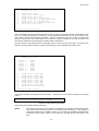
Contact Closure (digital input) Configuration
To set up the parameters for the contact closure (volt free) inputs, select 6 at the main menu. The following
menu should be displayed:
21
RMS compact
Knuerr RMS compact version X.X.X
Embedded Agent Setup
1.
2.
3.
4.
5.
6.
7.
8.
Change Contact Names
Change Contact Normal States
Change Contact Input Type
Change Contact OFF to ON Trap
Change Contact OFF to ON Trap
Change Contact ON to OFF Trap
Change Contact ON to OFF Trap
Exit Contact Closure Setup
Setup
Repeat Timers
Setup
Repeat Timers
Enter choice (ESC to exit):
Figure 24 Contact Closure Configuration
This menu enables the user set text descriptors for each contact input, as well as set the normal state for each
input (i.e. normally open/closed), and also to set the trap generation parameters for each of the contacts. The
user is able to specify when traps are generated – when the contact goes from OFF to ON, as well as when
going from ON to OFF. You are also able to set an option to repeat the sending of each trap, and also to set
how often the repeat trap is sent (assuming the alarm state is still present).
The other option in the Contact Closure configuration menu is Contact Closure Input Type. This refers to the
method by which an alarm condition is triggered. Selecting this option will display the following menu:
Knuerr RMS compact version X.X.X
Embedded Agent Setup
Contact
Contact
Contact
Contact
Contact
Contact
Contact
Contact
1.
2.
3.
4.
5.
6.
7.
8.
9.
1
2
3
4
5
6
7
8
:
:
:
:
:
:
:
:
LEVEL
LEVEL
LEVEL
LEVEL
LEVEL
LEVEL
LEVEL
LEVEL
Change Contact 1 Input Type
Change Contact 2 Input Type
Change Contact 3 Input Type
Change Contact 4 Input Type
Change Contact 5 Input Type
Change Contact 6 Input Type
Change Contact 7 Input Type
Change Contact 8 Input Type
Exit Contact Input Type Setup
Enter choice (ESC to exit):
Figure 25 Contact Closure Type
In the above example, all contacts are set to LEVEL – selecting one of the inputs will display the following
options:
Enter choice (ESC to exit): 1
Enter new Input Type 0=LEVEL,1=POSEDGE,2=NEGEDGE :
Figure 26 Contact Closure Type choices
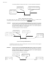
These three types have the following meanings:
LEVEL:
This option monitors the input in ‘real time’ and will reflect any changes in state that take place.
This means that if the input is switched on momentarily, then switched off, - both changes of
state will be registered by the RMS Compact. So, for example, if the RMS compacthas been
configured to send a trap for ‘alarm on’ and ‘alarm off’, the NMS will see these traps in real
time.
22
RMS compact
The following example (a normally closed contact - e.g. a door) should help to illustrate this:
Return to Normal (contact
closes) and alarm condition
clears
Alarm Condition
(contact opens)
Signal
state
for a normally
closed digital
input
+
-
Figure 27 : LEVEL Contact Closure monitoring
The following options are used when the user wishes to ‘latch’ an alarm signal. I.e. if an alarm occurs
momentarily, but the user wishes the alarm to remain present until manually reset by the user:
POSEDGE:
Primarily used when monitoring Normally Closed (NC) contacts, the alarm will be triggered
when the contact closure goes from a closed state (negative edge signal) to an open state
(positive edge signal). Once the alarm has been set, it will need to be manually reset by the
user (using either an SNMP set or using the ‘Reset’ button on the Viewer Programmer
application – this will be explained in more detail later.
The following diagram should help to explain this:
Alarm Condition
(contact opens)
Return to Normal
(contact closes)
Signal
state
for a normally
closed digital
input
Alarm condition
still present,
until manually
reset by the
user
+
-
Figure 28 Positive Edge (POSEDGE) Monitoring
If POSEGDE monitoring were used on a Normally Open contact, then the alarm would be triggered
when the contact returns to its normal state.
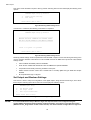
NEGEDGE:
Primarily used when monitoring Normally Open (NO) contacts, the alarm will be triggered
when the contact closure goes from an open state (positive edge signal) to a closed state
(Negative edge signal). Once the alarm has been set, it will need to be manually reset by the
user (using either an SNMP set or using the ‘Reset’ button on the Viewer Programmer
application – this will be explained in more detail later.
The following diagram should help to explain this:
Alarm Condition
(contact closes)
Return to Normal
(contact opens)
23
Signal
state
for a normally
open
digital
input
+
Alarm condition
still present,
until manually
reset by the
RMS compact
Figure 29 Negative Edge (NEGEDGE) Monitoring
If NEGEDGE monitoring were used on a Normally Closed contact, then the alarm would be triggered
when the contact returns to its normal state.
Note:
POSEDGE and NEGEDGE are used when monitoring sensors which generate transient signals, such
as shock sensors.
Shutdown Targets
The shutdown targets option refers to a feature whereby the user can configure the RMS compact to send a
shutdown signal to servers across the network which are running the appropriate ‘Network Shutdown Software’,
upon receipt of an alarm from an Uninterruptible Power Supply
Note:
If you wish to use this feature, you must purchase an additional ‘Network Shutdown Software’ to run
on each server on which shutdown is required, plus a licecnce key to enable this feature on the RMS
compact. To obtain more information about this software, please contact [email protected]
This feature is designed for use with an Uninterruptible Power Supply only
•
Firstly, Select "Shutdown Targets" in the RMS compact configuration screen (via HyperTerminal), this
should display the following screen:
Knuerr RMS compact version X.X.X
Embedded Agent Setup
Number of Targets Licenced: 0
1.
2.
3.
4.
5.
6.
7.
8.
9.
Update Target Licence Key
Powerfail timer
Battery depletion timer
Shutdown Targets 1-20
Shutdown Targets 21-40
Shutdown Targets 41-60
Shutdown Targets 61-80
Shutdown Targets 81-100
Exit Shutdown Target Setup
Enter choice (ESC to exit):
Figure 30 Shutdown Targets Configuration
•
Enter your Network Shutdown shutdown license key (this should have been provided with the RMS compact
if this feature was ordered).
•
Enter the IP addresses of the computers on the network you wish to shutdown
•
Setup the Power Fail and Low Battery timers to suit.
•
Exit and Save the configuration
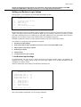
Reset to Default Settings
24
RMS compact
This option resets the RMS compact to factory presets. Selecting this menu item will display the following menu
options:
Knuerr RMS Compact ver 0.1.13
Embedded Agent Setup by Sinetica
1.
2.
Knuerr Default Settings
Exit Setup
Enter choice (ESC to exit):
Figure 30 Restoring default settings menu 1
If menu item 1 is selected, the following confirmation is requested:
Knuerr RMS Compact ver 0.1.13
Embedded Agent Setup by Sinetica
===============================================
WARNING THIS WILL OVERWRITE ALL CURRENT VALUES
AND WILL SET THE EEPROM TO THE DEFAULT SETTINGS
===============================================
Enter 1 to ignore 2 to proceed.
Enter choice (ESC to exit):
Figure 31 Restoring default settings menu 2
Restoring default settings will set all parameters within the RMS compact to those used during the testing of the
unit, this includes default IP information for both the RMS itself and for NMS and Trap receiver. Other default
settings include
•
Telnet enabled with default password of knuerr
•
HTTP access enabled with default user name of admin and a password knuerr
•
Temperature and humidity monitoring enabled on both ports
•
Default Contact Closure names with a default state of normally open and type level with all traps
disabled
•
No output Boolean logic configured
Set Output and Boolean Settings
This section is used to setup the configuration of the digital outputs, along with the Boolean logic, which drives
these outputs. Selecting option 9 from the main menu displays the following screen:
Knuerr RMS compact version X.X.X
Embedded Agent Setup
1.
2.
3.
Set Boolean values
Set Output values
Exit output/boolean menu
Enter choice (ESC to exit):
Figure 32 Boolean Logic Configuration Screen
Note:
It is recommended that setup of Boolean logic and output functions are configured using the
supplied RMS compact Viewer/Programmer software package, not using the serial interface option
(SEE the Viewer_Programmer section of this manual). The serial interface configuration for logic and
25
RMS compact
outputs should only be performed by users who have a thorough working knowledge of the RMS
compact PLEASE NOTE : NOR logic operations are not supported by the firmware
Setting up Boolean Logic Values
Selecting option 1 from the above menu will display the following screen:
Knuerr RMS compact version X.X.X
Embedded Agent Setup
1.
2.
3.
4.
5.
Set Boolean Input settings
Select AND or OR
Time On Delay
Time Off Delay
Exit Boolean Settings menu
Enter choice (ESC to exit):
Figure 33 Boolean Logic Configuration Screen
The Boolean logic function of the RMS compact enables the user to setup login functions to switch the relay
outputs of the RMS compact, and/or generate an SNMP trap. For example, in the event of receiving a contact
input alarm indicating that an air conditioning unit has failed, AND that an over temperature alarm has been
triggered, you may wish to receive a trap, and also switch on an additional cooling unit.
The RMS compact has a total of four logic operations (AND or OR), and 3 physical relay outputs.
The sequence of configuring a logic operation is as follows:
1.
Set Boolean Input settings
2.
Select which type of logic operation you wish to use for each output (AND or OR)
3.
Add any ON or OFF delays required
4.
Enable logic outputs
5.
Name Outputs
6.
Configure traps for logic outputs
1. Set Boolean Input settings
As outlined above, the first step is to specify which inputs will trigger a Relay output to be triggered. As
explained, there are 4 logical outputs in total, and these logic outputs can be all AND calculations, all OR
calculations or a mixture of both.
Selecting ‘Set Boolean Input Settings’ will display the following menu:
Knuerr RMS compact version X.X.X
Embedded Agent Setup
BOOLEAN
BOOLEAN
BOOLEAN
BOOLEAN
1.
2.
3.
4.
5.
INPUT
INPUT
INPUT
INPUT
LOGIC
LOGIC
LOGIC
LOGIC
1:
2:
3:
4:
1,2
3,4
5,6
7,8
Change Boolean 1
Change Boolean 2
Change Boolean 3
Change Boolean 4
Back to prev menu
Enter choice (ESC to exit):
Figure34 Configure Logical Inputs
This screen enables configuration of up to four logic operations.
26
RMS compact
To add an input number to the relevant logic calculation, select the relevant logic calculation (e.g. ‘Change
Boolean 1’ ), and add the input number (-ve number mean that the input is inverted for logic purposes). The
above applies to both AND and OR calculations
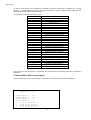
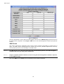
The Inputs are numbered in the following way:
Input Number
1
2
3
4
5
6
7
8
9
10
11
12
13
14
15
16
17
18
19
20
21
22
23
24
25
26
27
28
29
Input Description
Contact Closure 1
Contact Closure 2
Contact Closure 3
Contact Closure 4
Contact Closure 5
Contact Closure 6
Contact Closure 7
Contact Closure 8
Temperature 1 LowerControl Limit
Temperature 1 Lower Warning Limit
Temperature 1 Upper Warning Limit
Temperature 1 Upper Control Limit
Humidity 1 LowerControl Limit
Humidity 1 Lower Warning Limit
Humidity 1 Upper Warning Limit
Humidity 1 Upper Control Limit
Temperature 2 LowerControl Limit
Temperature 2 Lower Warning Limit
Temperature 2 Upper Warning Limit
Temperature 2 Upper Control Limit
Humidity 2 LowerControl Limit
Humidity 2 Lower Warning Limit
Humidity 2 Upper Warning Limit
Humidity 2 Upper Control Limit
Temperature 1 Upper (Hysteresis)*
Temperature 1 Lower (Hysteresis)*
Temperature 2 Upper (Hysteresis)*
Temperature 2 Lower (Hysteresis)*
Feedback Latch
Table 1: Input Numbering
*The functions of the Temperature 1 (Hysteresis) and Temperature 2 (Hysteresis) inputs will be explained in
Appendix A
2. Select AND or OR for each output
Choose ‘Select AND or OR’ from the Boolean logic menu, and the following screen will be displayed:
Knuerr RMS compact version X.X.X
Embedded Agent Setup
BOOLEAN
BOOLEAN
BOOLEAN
BOOLEAN
1.
2.
3.
4.
SELECTED
SELECTED
SELECTED
SELECTED
Change
Change
Change
Change
1:
2:
3:
4:
Boolean
Boolean
Boolean
Boolean
AND
AND
OR
OR
Selection
Selection
Selection
Selection
1
2
3
4
27
RMS compact
5.
Back to prev menu
Enter choice (ESC to exit):
Figure 35 Select AND or OR Screen
Choose AND or OR for each logical output
3. Add any ON or OFF delays required
Once a desired logic condition has occurred, (e.g. inputs 1 AND 2 are present), then the user may introduce a
delay before the output is set (to allow for rapid or erroneous changes in input condition). The same is true for
clearing of an output once the condition has cleared. These timers are set by selecting the ‘Time On Delay’ or
‘Time Off delay’ from the Boolean menu
4. Enable Logic Outputs
Selecting the ‘Set Output Values’ option from the Boolean menu will display the following screen:
Knuerr RMS compact version X.X.X
Embedded Agent Setup
1.
2.
3.
4.
Enable Outputs
Change Output Names
Trap Controls
Exit settings Menu
Enter choice (ESC to exit):
Figure 30 Setting Output Values Configuration Screen
To enable logic outputs. Select option 1 in the above menu, this should display the following screen:
Knuerr RMS compact version X.X.X
Embedded Agent Setup
OUTPUT 1:
OUTPUT 2:
OUTPUT 3:
1.
2.
3.
4.
Enabled
Enabled
Enabled
EnableOutput
EnableOutput
EnableOutput
Back to prev
1
2
3
menu
Enter choice (ESC to exit):
Figure 31 Enable Outputs Screen
This screen enables or disables Relay outputs.
3. Name Outputs
Option 2 in the Setting Output Values Configuration Screen, enable the user to configure a text descriptor for
each output.
4. Configure traps for logic outputs
Selecting this option will display the following menu:
Knuerr RMS compact version X.X.X
Embedded Agent Setup
1.
2.
3.
4.
Trap
Trap
Trap
Trap
Off to On
Off to On
On to Off
On to Off
Enables
repeat Timer Settings
Enables
repeat Timer Settings
28
RMS compact
5.
Exit Output Traps Menu
Enter choice (ESC to exit):
Figure 32 Configure Output Traps Screen
In this screen the user sets the conditions for sending traps on each output being triggered (OFF to ON or ON
to OFF), as well as setting repeat timers for each type (if required).
To Save and Exit
If you are satisfied with your configurations, save them and exit. To save, press ‘Exit Setup’
The screen displays the following message:
Knuerr RMS compact version X.X.X
Embedded Agent Setup
1.
2.
3.
4.
5.
6.
7.
8.
9.
10.
Network Configuration
Net Access Configuration
NMS Configuration
Trap Host Configuration
Temp & Humidity Configuration
Contact Closure Configuration
Shutdown Targets Configuration
Restore Default Settings
Set Output and Boolean Settings
Exit Setup
Enter choice (ESC to exit): 10
*** WARNING *** Configuration changed
Esc to ignore changes, 1 to use for this session, 2 save:
Figure 33 Exit setup Messages For Configuration
The user can choose to save or discard changes made.
Note:
Changes must be saved to take effect (select ‘Exit setup’ followed by (2) to save).
When configuration complete, remove power & turn DIP switch 1 on the RMS compact from the
DOWN (ON) position to the UP (OFF) position
29
RMS compact
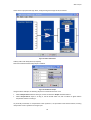
Configuration using an Internet Browser
This section explains which parameters can be configured using an Internet browser such as Internet Explorer.
Once the unit has been given an IP address, (see previous section), then it can be configured using the HTTP
interface.
To connect to the HTTP interface, start your browser, and point it at the IP address for the RMS compact (e.g.
http://10.1.1.162). This should display the following logon screen:
Figure 34: Login screen
Login using the HTTP username & password configured during the serial port configuration session. The
default settings are User: admin, password: knuerr
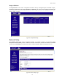
Main Status Page
Once logged in, the following main status page is displayed:
30
RMS compact
Figure 35: Main Status Page
This page is designed as a status summary page, showing the current status of digital inputs and outputs, along
with the current temperature and humidity readings, with a green tick showing normal/non-alarm status and the
red cross showing non-normal/alarm status. In the Environmental status window, an amber icon states that the
temperature has breached one of the warning limit thresholds.
Input Status
The Input Status page gives more information about the configuration of the digital inputs, along with an
indication of the current ststus of each contact, as follows:
Figure 36: Input Status Page
31
RMS compact
Output Status
The Output Status screen shows configuration information relating to the digital Outputs of the RMS compact,
including its configuration status (either Enabled or Disabled), and any ON or OFF delays configured (see
serial configuration section for an explanantion of how these delays function). It also displays the current status
of each output, as follows:
Figure 37: Output Status Page
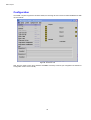
Network Setup
The Network Setup page shows configuration details for the RMS compact, it’s associated Netwrk
Management Stations (NMSs), and trap receivers. The user is also able to check the MAC address of the RMS
compact and its BootType (preconfigured IP address, DHCP assigned or BOOTP assigned) from here.
Figure 38: Network Setup Page
32
RMS compact
Selecting the 'Force Logout' option from the menu, will log the user out of the session
33
RMS compact
Configuration using the RMS compact Programmer Software
Introduction
RMS compact Programmer is a custom designed viewing and management package for the RMS compact unit.
It enables the user to configure and monitor the RMS compact unit without the need for an NMS, (although RMS
compact Programmer can also be used in conjunction with an NMS), and provides an intuitive Graphical User
Interface (GUI), with which the RMS compact can be monitored and configured.
The RMS compact Programmer uses SNMP and Java technologies to view and manage the RMS compact ,
and allows the user to monitor the state of the inputs and outputs.
System Requirements
The version of RMS compact Programmer contained in this package supports systems running:
•
Windows 2000/XP/2003
The software also requires the following:
•
Connection to the network that the RMS compact is connected to.
•
Internet Explorer 4 or above (To utilise its Java Runtime Environment) / Netscape Navigator 4.0 or above
•
The network address of the PC that the RMS compact Programmer is running on must be entered into the
NMS table of the RMS compact (see configuration section).
Installation
This section describes installation of the RMS compact Programmer software on a Windows 2000/XP/2003
platform.
•
Insert the supplied CD-ROM ‘RMS compact Support Software’ and select the ‘RMS compact‘ directory,
followed by the ‘Programmer’ directory.
•
Select the ‘RMS Compact Install.exe’ file and run. Follow onscreen instructions.
Once installed, the program is started by selecting the ‘RMS compact Programmer’ icon from the SINETICA
directory in the Start Menu.
Note:
The IP address of all PC’s accessing the RMS compact using the Viewer_Programmer software tool,
MUST be in the NMS table of the RMS Compact
34
RMS compact
Configuration
Once RMS compact Programmer has been started, the first thing the user must do is select Connect from File
menu as follows:
Figure 39 Connect to unit
Next, the user needs to enter the IP address and SNMP community of the unit, (as configured in the Serial Port
Configuration section of this manual).
35
RMS compact
Figure 40 IP Address & SNMP community string
The following screen shows the main viewing screen for the RMS compact Programmer:
Figure 41 : RMS compact Programmer Main viewing screen
This screen displayed the current state of the contact closures along with the current temperatures & humidities,
(if temperature and humidity sensors are installed), along with the state of the logic outputs.
36
RMS compact
Configure Unit Menu
The drop down menu with the heading Configure unit, has the following options:
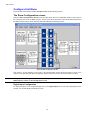
The Show Configuration screen
Selecting Show Configuration Screen from this menu starts the main configuration window. This screen is
the main setup screen for the RMS compact , and it is from this screen that it is recommended that the bulk of
the RMS compact setup is done. Selecting this option displays the following screen:
Figure 42: Main Configuration Screen
This screen is a logic diagram of the inputs on the left-hand side, running through the layers of logic, to the
outputs on the right hand side. Most configuration options (other than TCPIP can be performed from here).
Note:
Changes are not actually committed to the RMS compact until the data is saved using the ‘Save to
RMS compact ’ button on the configuration screen.
Digital Input Configuration
To select the option to be configured Single click on the ‘Digital Inputs’ box in the main configuration screen
window – this should display the following screen:
37
RMS compact
Figure 43 : Digital Inputs Configuration
This screen allows the user to configure the NAME of the digital Input, its NORMAL STATE (normally open or
normally closed), and it’s TYPE (i.e LEVEL, POSEDGE or NEGEDGE – see serial configurtaion section of this
manual for an explanation of each type)
Note:
It is not possible to use the vowel mutations “Umlaut” and "ß" for any of the input or output names
Temperature & Humidity Input Configuration
Selecting the Analogue Inputs section on the main configuration, will display the following screen:
Figure 44: Temperature & Humidity Input Configuration
From here, the user can set the THRESHOLDS for Temperature and Humidity limits, ENABLE OR DISABLE
Temperature or Humidity monitoring, change the NAMES of the Temperature & Humidity inputs and set a
CALIBRATION OFFSET.
Digital Input Trap Configuration
Selecting the Trap Setup window connected to the Digital Inputs window on the main configuration screen,
will display the following window:
38
RMS compact
Figure 45: Contact Closure Trap Configuration
This screen enables the user to setup the circumstances by which an SNMP trap is generated in relation to the
contact closure inputs. Firstly traps can be ENABLED or DISABLED for an OFF to ON or an ON to OFF
transition, and also REPEAT TIMERS can be set if traps need to be continually send in an alarm situation.
Note:
The Minimum Setting for a Trap Repeat Timer is 30 seconds.
Temperature & Humidity Trap Configuration
Traps for the Temperature & Humidity inputs are setup by selecting the Trap Setup box connected to the
Analogue Inputs window in the main configuration window. This will display the following window, whose
options are the same as the Contact Closure Trap options.
Figure 46: Temperature & Humidity Trap Configuration
Note:
The Minimum Setting for a Trap Repeat Timer is 30 seconds.
Logic Configuration Screens
39
RMS compact
The four central blocks on the main configuration window relate to the four logic outputs available within the RMS
compact. Selecting one of these blocks will display a window as follows (output 1 selected):
Figure 47: Logic Configuration Screen
The inputs are displayed on the left of the screen – to select an input to be used in this logic calculation, select
Add New Input from the Inputs drop down menu. The user then selects the type of logic operation (AND or
OR), followed by any delays that need to be introduced - the user may introduce a delay before the output is set
(to allow for rapid or erroneous changes in input condition). The same is true for clearing of an output once the
condition has cleared. These timers are set by selecting the ‘ ON Time Delay’ or ‘OFF Time Delay’ .
Note:
Although there are only 3 relay outputs on the RMS Compact, there are 4 possible logic calculations
available. The calculations 1 –3 relate to the physical outputs, whilst number 4 is a purely logic based
calculation used for generating traps based upon a pre-defined set of input parameters. PLEASE
NOTE : NOR logic operations are not supported by the firmware
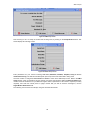
Output Trap Configuration
The second from right box configures the output trap parameters as follows:
40
RMS compact
Figure 48: Logic Output Trap Configuration
Firstly, the user may ENABLE or DISABLE traps for OFF to ON or ON to OFF transitions of the logic outputs,
plus change the REPEAT TIMERS if required.
Note:
The Minimum Setting for a Trap Repeat Timer is 30 seconds.
Relay Output Configuration
The final area of configuration is the settings for the physical relay outputs:
Figure 49: Relay Output Configuration
This screen enables the logic previously configured, to switch a physical output on the RMS compact . From
this screen, the physical outputs are ENABLED OR DISABLED and assigned a NAME.
The ‘File’ Menu
Connect & Disconnect
Selecting Connect will prompt the user to enter the IP address of the RMS compact required (see the
beginning of this section of the manual, titled Configuration.
Poll Rate
This defines how often the RMS compact is polled over the network. This will obviously have an impact on
network traffic, and should therefore be used with some care.
SNMP Settings
41
RMS compact
Selecting this option will display the following screen:
Figure 50: SNMP Default settings
Explanations of both settings are given in the window above.
Load from unit
Uploads the existing configuration from the RMS compact into the Viewer/Programmer. – NOTE: Unless
Autosave to Unit is enabled (see below), this will overwrite any changes made in the configuration in the
viewer until Save to Unit has been executed.
Saving the Configuration to the RMS compact
Once all configuration options have been set, it is necessary to save the configuration to the RMS compact , by
selecting the ‘Save To RMS compact ’ button. Selecting this button should send the configuration to the RMS
Compact, displaying a progress bar during the download.
Saving the configuration to a file for downloading into another RMS compact
Under the Configure RM S compact menu, there are two options, called Save to File and Load from file,
this enables the user to save the configuration of the RMS compact unit to a file on a PC or server. This
configuration file can then be recalled and downloaded into an alternative unit (or into the same unit for backup
purposes).
Once the configuration of the unit is complete, select the Save to File button from the File menu. You will then
be prompted for a file location and filename.
To recall this configuration file at a later time, just select the Load from File button and locate the file. The
settings form this file will be recalled into the Viewer/Programmer for downloading into another unit.
Saving Viewer Configuration
It is possible to save the configuration of the viewer/programmer software in addition to the configuration of the
RMS compact itself. This will save the following settings:
•
Poll Rate
•
SNMP Seetings
•
Any Actions set
•
SMS Settings
•
Logging settings
Selecting Save Viewer Configuration will prompt the user to save the config (.ini) file to a user defined
location. Load Viewer Configuration will restore settings made in this file.
Note:
There are two different software streams of the RMS compact Viewer/Programmer software (version
1.x.x and version 2.x.x) – Version 1.x.x of the viewer WILL NOT support configuration files created on
42
RMS compact
a 2.x.x version of the Viewer/Programmer. Configuration files created on Version 1.x.x ARE
SUPPORTED on Viewer/Programmer version 2.1.1 and above only.
Setup Menu
Configure Actions
This screen enables the user to setup pre-defined actions for each alarm using batch files. A batch file can be
run for each alarm generated by the RMS compact, including all input alarms (Contact Closures &
temp/humidity), plus boolean logic output alarms. Selecting the Actions menu, will display the following screen:
Figure 51: Set Actions screen
Running Batch Files
To run a batch file in the event of an alarm on the RMS compact, first enter a value for the Timer – this value is
displayed in minutes, and refers to the delay between receiving the alarm condition, and running the batchfile.
For example, we will use the Temperature 1 UCL alarm as a trigger:
43
RMS compact
Figure 52: Batchfile Setup
Once the timer value has been set, enter the FULL PATH to the batchfile into the Batch File field (including the
drive letter). In the example above, we have a batchfile that will send a broadcast message to an administrator,
informing the temperature threshold has been breached. The contents of this file might be:
net send administrator Rack over temperature
(for example) This batchfile will run 2 minutes after the alarm has been raised by the RMS compact unit.
Sending an SMS Message
An SMS message is configured, simply by typing a text string into the SM S M essage field of the action screen,
for example :
44
RMS compact
Figure 53: SMS Action
Once the Temperature 1 (UCL) alarm has been triggered, the text in the SM S M essage Field will be sent to
the SMS number configured in the Configure SM S menu of the Viewer/Programmer software (see previous
section)
SMS Screen
This screen configures the parameters need to send to send a message (using SMS) to a mobile phone or
pager. The RMS compact viewer/programmer software uses the TAP ('Telocator Alphanumeric Protocol').
Communication protocol to send messages to the SMS bureau.
Note:
The SMS bureau to be used must support the TAP communication protocol. Your network supplier
should be able to tell you if they have a TAP bureau.
Note:
A Hayes compatible modem installed on the PC running the Viewer/Programmer software is required
to send SMS messages
First, select SM S from the Setup menu. The following screen should be displayed:
45
RMS compact
Figure 54: SMS setup screen
This first thing to do is to setup the modem that is being used, by clicking on the Setup M odem button. This
should display the following screen:
Figure 55: Modem setup screen
Enter parameters for your modem including Com Port, Baudrate, databits, Stopbits, Parity & Modem
initialisation String. The data format will depend upon the specific TAP bureau that is being used.
Once the modem is configured, Save Values and Close to return to the SMS setup screen. Back in the SM S
Setup window, enter an outside line access number if required, then enter the SMS TAP Bureau Number this
number should be obtained from your Network supplier. Enter a password for the bureau if required (it is rarely
required), then enter the mobile phone or pager number that you wish to send the message to, into the
Pager/M obile ID Number field.
The following screen shows an example, using the UK based O2 bureau:
46
RMS compact
Figure 56: Example SMS setup
The Standard CR field will also depend on whether the bureau supports standard Carriage Return or Carriage
Return and Line Feed – again, the bureau supplier should be able to tell you this.
It is possible to send a Test M essage to check your configuration details. Just enter a message in the Test
M essage field, and hit the Send M essage button.
If the Test Message is successfully received, then you can now go onto configuring the Viewer software to
send an SMS message for specific alarms, using the Configure Actions feature as explained in the following
section.
Logfiles
This screen gives the option to setup logfiles for values and for alarms (and to set a maximum logfile size).
There are two types of data logging that the user can perform, these are Values and Alarms.
Figure 57: Advanced Features
Values Logging
If Values logging is selected (i.e. a logging filename is provided), then a ‘snapshot’ of the status of the RMS
compactwill be logged to a file every time the unit is polled. The status of all inputs will be logged on each poll.
For example:
11/09/2002 15:00:00 GMT
Contact_1
normal
Contact 2
normal
Contact 3
normal
Contact 4
normal
Contact 5
normal
Contact 6
normal
Contact 7
normal
Contact 8
normal
Temperature1 Warning 22.5°C
Humidity1 Warning
40.6%
Temperature2 Warning 22.9°C
47
RMS compact
Humidity2 Warning
37.3%
Figure 58: Values Logfile
Alarms Logging
If Alarms logging is selected (i.e. an Alarms log filename is provided), then an entry will only be added to the
logifle when an alarm condition occurs.
For example:
11/09/2002 15:08:47 GMT
Humidity1 Warning
Entering alarm state
Humidity1
Entering alarm state
11/09/2002 15:09:02 GMT
Temperature1 Warning Entering alarm state
11/09/2002 15:09:12 GMT
Temperature1
Entering alarm state
11/09/2002 15:09:17 GMT
Temperature1 Warning Returning to normal state
Temperature1
Returning to normal state
Figure 59: Alarms Logfile
Timezones
It is also to set the local timezone (based on an offset from GMT), plus the option to listen for SNMP traps in
addition to the normal polling routine and also the option to save a RMS compact setup profile and load a predefined profile.
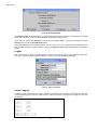
The Control Menu
Input Contact Reset
If Positive Edge or Negative Edge trigger mode is selected in the Input Contact Setup section, then if an
alarm condition is detected on the digital input, it will ‘Latch’ the condition – i.e. it will stay in alarm mode until
manually reset. Selecting this menu, and hitting the Reset Trigger button for the relevant contact, will reset the
digital input to it’s non- alarm state.
Figure 60: Digital Input contact reset screen
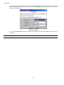
Output States
48
RMS compact
The RMS compact Viewer/Programmer software, also offers the ability to manually set the status of the output
relays, overiding the status of the input logic. Firstly, select Output States from the Control menu. This should
display the following screen:
Figure 61: Set Outputs
To set an output ON or OFF regardless of the state of its input logic, just select either ON or OFF from the pull
down menu.
Note:
The logic inputs will not be re-enabled until Re-Enable is selected from the pulldown menu.
49
RMS compact
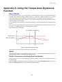
Appendix A: Using the Temperature Hysteresis
Function
How it Works
The Hysteresis functionality on both Temperature 1 and Temperature 2 inputs, is an additional temperature
threshold, which enables the RMS compactto switch on a cooling fan or heater unit within a rack, once the
temperature reaches the Upper Warning Limit (UWL) threshold or Lower Warning Limit (LWL) threshould.
In the case of Temperature Upper Hysteresis ,the cooling fan will remain on until the temperature drops 4
degrees centigrade below the UWL.
For Temperature Lower Hysteresis, the heater unit will remain on until the tenmperature rises 4 degrees above
the LWL.
This is done to try and prevent ‘bounce’ of the relay output, and the temperature hovers around the UWL or LWL
threshold, i.e. so that the relay does not continually switch on and off.
This is illustrated in the graph below:
Fan switch ON Fan switch OFF
UWL Threshold
UWL minus 4 degrees
Temperature
Figure 62: Temperature Hysteresis function
The inverse of the above is true for Temerature Lower Hysteresis.
Setup
The best way to configure the Temperature Hysteresis function is to use the RMS compactViewer/Programmer
software provided. Below is a description of the steps required:
Enable Temperature monitoring & set thresholds
The first step is to make sure that temperature monitoring is enabled, and to set your temperature threshold to
the desired levels.
Start up the RMS compactViewer/Programmer software, and go to the Configure RMS compact section, and
click on the Analogue Inputs box- you should see the following window:
50
RMS compact
Figure 63: Enable Temp inputs & set Thresholds
As explained above, the threshold that will trigger the fan to switch on, is the UWL threshold, the threshold to
trigger the heater to switch on is the LWL threshold – therefore ensure that these are correct.
Setup logic
The next step is to setup the RMS compactlogic to perform the switch on of the fan or heater.
Depending upon which output the fan or heater is wired into, select the relevant logic block (we will use output 1
as an example – i.e the Fan triggered by Temperature Upper Hysteresis)
Once opened, select Add new Input from the drop down menu, and select Temperature 1 Upper
Hysteresis (or Temperature 2 Hysteresis if required), as follows:
Figure 64: Select logic Input
51
RMS compact
As this is the only input to this logic block, change the logic block type to OR, as follows:
Figure 65: Select OR function
Add any ON or OFF delay timers (if required).
Now ensure that the relevant relay output is enabled:
Figure 66: Enable Fan Output
Using the above example, the following sequence of events should now occur:
•
When Temperature1 reaches 25 deg C, the fan connected to Output 1 should switch on.
•
When Temperature1 drops to 20 deg C, the fan should switch off, and not switch on again until the
temperature returns to 25 deg C.
As previously mentioned, for Temperature Lower Hysteresis , the procedure is the same as above, but using
Temperature Lower Hysteresis as a logic input.
52
RMS compact
Appendix B
Sensor Details
This section explains the sensor options available with the RMS compact product, along with a brief explanation
of how they interface to the unit.
Digital Input sensors
This section explains a selection of sensors that can be connected to the Digital Inputs of the RMS compact
Door Sensor
P/N 01.108.115.9
Used for monitoring access to a cabinet or room, these magnetic bridge sensors operate on all magnetic
materials.
Supplied with 4m cable & fixing material.
Physical Appearance
Connector
Plugged into RM S compact
Example shows sensor plugged into
Digital Input 1
Bare Ended
Shock Sensor
P/N 06.108.113.9
Monitors movement of a rack – for example if forced entry is attempted.
Non-positional vibration sensor. , ABS plastic enclosure measuring 70x70x25mm
Contacts open when unit is at rest.
Operating Temp –10 to +70 deg C
Supplied with 4m cable
Note:
For effective operation, the +ve and –ve wires must be connected up correctly to the +ve and –ve
terminals on the RMS compact digital input connector
Physical Appearance
Connector
53
Plugged into RM S compact
RMS compact
Bare Ended
Example shows sensor plugged into
Digital Input 1
Smoke Sensor
P/N 06.108.111.9
For smoke detection within a rack or room.
Scattered-light sensor for early detection of fires, with alarm memory and alarm indicator
Low voltage operation 8v – 28v. The optical smoke sensor is particularly suitable for detecting visible smoke
from smouldering fires (light smoke) or fires with restricted oxygen supply, as well as open fires.
Sensor specification DIN EN 54 T 7, German insurance accreditation (VdS) G 292 19
Standby current: 40µA; Alarm Current: 9mA; Temp range: -20 to 72 degC; Humidity range: 95% RH;
Dimensions: 95mm, 94mm height
Supplied with:
4m cable
Mounting material
Description
Physical Appearance
Connector
Plugged into RM S compact
Example shows sensor plugged into
Digital Input 1
Bare Ended
Water Level Sensor
P/N 06.108.117.9
Float type water level sensor
Supplied with 4m cable
Physical Appearance
Connector
54
Plugged into RM S compact
RMS compact
Example shows sensor plugged into
Digital Input 1
Bare Ended
Analogue Input Sensors
Temperature & Humidity Sensor
P/N 06.108.112.9
Provides both temperature and relative humidity monitoring within one unit. ABS plastic enclosure measuring
70x70x25mm
Supply voltage 5v DC +/- 5% (supplied by Hawk-I); Current: Max 5A;
Temperature range – 0 to 60 deg , accuracy +/- 5%
Humidity Range 30% to 90% relative humidity, accuracy 5% RH @ 25degC, 60% RH.
Supplied with 4m cable
Physical Appearance
Connector
Plugged into RM S compact
Example shows sensor plugged into T/H
input 1
RJ 4/4
Temperature Sensor
P/N 06.108.110.9
Temperature only sensor. ABS plastic enclosure measuring 70x70x25mm
Operating Temp: -40 to +250 degC; Thermal time constant: 7 sec (cooling in air); Dissipation factor: 3mw/K;
Resistance: 50k ohms +/-3%
Supplied with 4m cable:
Physical Appearance
Connector
55
Plugged into RM S compact
RMS compact
Example shows sensor plugged into T/H
input 1
RJ 4/4
ECO Temperature Sensor
P/N 06.108.120.9
Temperature only sensor. ABS plastic enclosure measuring 70x70x25mm
Operating Temp: -40 to +250 degC; Thermal time constant: 7 sec (cooling in air); Dissipation factor: 3mw/K;
Resistance: 50k ohms +/-3%
Supplied with 4m cable:
Physical Appearance
Connector
Plugged into RM S compact
Example shows sensor plugged into T/H
input 1
RJ 4/4
AC Voltage Monitoring Sensor
P/N 06.108.122.9
Monitors AC Power via a fixed IEC Euro connector.
Monitored AC Voltage 230V 50/60
Supplied with 4m cable & Mounting kit:
Physical Appearance
Connector
56
Plugged into RM S compact
RMS compact
Bare Ended
Example shows sensor plugged into
Digital Input 1
Passive Infrared Movement Sensor
P/N 06.108.114.9
Room Monitoring with the latest state of the art technology
VdS approval : Classes A +B, Volumetric lens range 2-16m, Long Lens range 29-50m, Curtain lens range 1730m, manipulation monitoring, digital fault evaluation, corner or wall mounted
Supplied with 4m cable & Mounting kit:
Physical Appearance
Connector
Bare Ended
Plugged into RM S compact
Example shows sensor plugged into
Digital Input 1
This list is continually being updated, please contact Knürr for further information.
Appendix C: Serial/TFTP Firmware Upgrades
Using the supplied RMS compact SerialTFTP software, it is possible to upgrade the firmware version of the
RMS Compact, to add patches and new features.
Install
To install the SerialTFTP upgrade software, simply cd to the relevant directory on the supplied Cdrom, and run
the SerialTFTP.exe installation script.
Now copy the firmware files to an accessible directory on your hard drive (these should be supplied by Sinetica
Corporation)
Run SerialTFTP
From the Start menu of your PC, select the SerialTFTP option.
The user now has two methods of upgrading the RMS compactfirmware, either using a serial port to
serial port connection between the RMS compactand the PC, or using the TFTP protocol over the
TCP/IP network.
Starting the SerialTFTP program should display the following screen:
57
RMS compact
Figure 67: SerialTFTP Firware Upgrade Tool Screen
TFTP Upgrade
TFTP is the quickest, and preferred, method of upgrading the firmware in the RMS Compact. Instructions for
performing the upgrade are shown below:
•
In the firmware settings box, select the location of the firmware files that you saved on
your hard drive, and select Generic (main) as a product type
•
in the transfer mode box, select TFTP
•
In the TFTP Settings box, enter the IP address of the RMS compact to be upgraded
•
Hit the Upgrade button
•
At the end of the process, you should see an Upgrade Successful message, and the
checksums should match.
•
Online instructions are also given in the Information window of the software tool itself.
The following screenshot shows an example the SerialTFTP upgrade software, in TFTP mode:
58
RMS compact
Figure 68: SerialTFTP Tool in TFTP Mode
Serial Upgrade
The serial upgrade option utilises a serial port to serial port connection between the RMS compactand the PC
running the upgrade tool.
There are a number of parameters which must be setup before the downloader can be used, as follows:
Port : Select the Com port being used on your PC/Server
Baud: Set the baud rate at which the serial download process runs (product dependent).
Location: The location of the download files on your disk drive – these must be copied to a directory on
your hard disk before attempting the download process.
Product: Select the product and variant type from the drop down menu.
•
Connect the configuration cable (NC-CFG) between the Comm port of your PC and the port labeled
‘RS232’ on your RMS Compact.
•
Ensure that the DIP switch settings on the RMS compactare as follows – DIP switch 1 UP, DIP switch 2
DOWN.
•
Disconnect the power from the RMS Compact.
The RMS compactis now ready to be upgraded:
•
On the SerialTFTP Upgrade tool screen select the UPGRADE button – this should set the port status to
OPEN, and display the expected checksums for this version.
•
Now re-apply the power to the RMS compact– you should see text displayed in the Data window of the
downloader, and the progress bar should start to increment, until the first block of data is complete, then it
will start on the next block.
•
When complete, you should see UPGRADE SUCCESSFUL displayed in the data window.
If this process fails, and the checksums do not match up, resend the data using the RESEND button on the
downloader.
59
RMS compact
Appendix C
This appendix has two sections: Reference and Troubleshooting.
Reference
This section discusses Communities, IP Addresses, Sub net masking, and routers/gateways.
Communities
A community is a string of printable ASCII characters that identifies a user group with the same access
privileges. For example, a common community name is “public.”
For security purposes, the SNMP agent validates requests before responding. The agent can be configured so
that only managers that are members of a community can send requests and receive responses from a
particular community. This prevents unauthorized managers from viewing or changing the configuration of a
device.
IP Addresses
Every device on an internetwork must be assigned a unique IP (Internet Protocol) address. An IP address is a
32-bit value comprised of a network ID and a host ID. The network ID identifies the logical network to which a
particular device belongs. The host ID identifies the particular device within the logical network. IP addresses
distinguish devices on an internetwork from one another so that IP packets are properly transmitted.
IP addresses appear in dotted decimal (rather than in binary) notation. Dotted decimal notation divides the 32-bit
value into four 8-bit groups, or octets, and separates each octet with a period. For example, 199.217.132.1 is
an IP address in dotted decimal notation.
To accommodate networks of different sizes, the IP address has three divisions - Classes A for large, B for
medium, and C for small. The difference among the network classes is the number of octets reserved for the
network ID and the number of octets reserved for the host ID.
Class
Value of First Network ID
Octet
Host ID
Number of
Hosts
A
1-126
first octet
last three octets
16,387,064
B
128-191
first two octets
last two octets
64,516
C
192-223
first three
octets
last octet
254
Any value between 0 and 255 is valid as a host ID octet except for those values the InterNIC reserves for other
purposes.
Value
Purpose
0, 255
Subnet masking
127
224-254
Loopback testing and interprocess communication on
local devices
IGMP multicast and other special protocols
Subnetting and Subnet Masks
Subnetting divides a network address into subnetwork addresses to accommodate more than one physical
network on a logical network.
For example: A Class B company has 100 LANs (Local Area Networks) with 100 to 200 nodes on each LAN.
To classify the nodes by its LANs on one main network, this company segments the network address into 100
60
RMS compact
subnetwork addresses. (If the Class B network address is 150.1.x.x, the address can be segmented further
from 150.1.1.x through 150.1.100.x.)
A subnet mask is a 32-bit value that distinguishes the network ID from the host ID for different subnetworks on
the same logical network. Like IP addresses, subnet masks consist of four octets in dotted decimal notation.
You can use subnet masks to route and filter the transmission of IP packets among your subnetworks. The
value “255” is assigned to octets that belong to the network ID, and the value “0” is assigned to octets that
belong to the host ID.
For the example above, if you want all the devices on the subnetworks to receive each other’s IP packets, set
the subnet mask to 255.255.0.0. If you want the devices on a single subnetwork only to receive IP packets from
other devices on its own subnetwork, set the subnet mask to 255.255.255.0 for the devices on that subnetwork.
Subnet M ask
0.0.0.0
255.0.0.0
255.255.0.0
255.255.255.0
Routing and Filtering
IP packets are transmitted to all devices.
IP packets are only transmitted to devices
whose IP address’s first octet matches the
sender’s IP address’s first octet.
IP packets are only transmitted to devices
whose IP address’s first two octets match
the sender’s IP address’s first two octets.
IP packets are only transmitted to devices
whose IP address’s first three octets match
the sender’s IP address’s first three octets.
Gateways
Gateway, also referred to as a router, is any computer with two or more network adapters connecting to different
physical networks. Gateways allow for transmission of IP packets among networks on an internetwork.
Troubleshooting
Problem:
The TES (Terminal Emulation Software) does not display anything.
Solution:
M ake sure the Dipswitch is set correctly. Switch 1 is ON when DOWN and Switch 2 is
UP. This applies only when you power up.
M ake sure the TES’s communication parameters are correct. They should be 38400
baud rate, no parity, 8-data bits, and 1 stop bit.
M ake sure the ends of the NC-CFG cable are plugged into their respective ports.
The ends of the cable indicate which belongs to the CPU and which belongs to the RMS
compact .
The end of the hooded cable nearest the label belongs to the CPU, and the end farthest away
belongs to the RMS compact .
If DIP switch set correctly and cable correctly connected, power off/on the RMS
compact and the main menu should be displayed.
PROBLEM:
Solution:
The NMS cannot ping the RMS compact .
M ake sure there is a network connection to the RMS compact.
Sporadic incompatibilities to switch ports can be fixed by disabling auto-negotiation mode
at the specific switch port and setting it manually to 10Mbps and halfduplex mode.
Solution:
M ake sure the cable is in good condition.
Solution:
Try pinging the RMS compact from another computer on the same network segment
as the RMS compact .
Solution:
M ake sure to set the Community String [Set Access Controls, Type 2, Set 1 through
4]. Follow these steps:
Name the community with any lowercase name. (A UPS monitors a designated community.)
Solution:
M ake sure to set the M anager Table. Set Access Controls, Type 3, Set 1 through 4].
Follow these steps:
61
RMS compact
Define the Manager IP Address, Community string, and Access Permission together.
The trap manager’s community should be the same name as the name of the community it
monitors.
The trap manager’s status is set to Accept YES to enable sending TRAPs or to Accept to No
to disable.
62
RMS compact
Appendix D: Configuring the NMS
Note:
These instructions are only a guide, please refer to the NMS manufacturer manuals for accurate
instructions.
To complete the RMS compact installation and configuration process, you must compile the necessary MIB to
configure the NMS.
Any suitable SNMP based NMS with a MIB compiler can manage the RMS compact adapter. For instructions
on how to compile MIBs please refer to the documentation supplied with the NMS.
General Network Management Stations
Follow these general procedures to configure an NMS:
•
•
•
Compile the device MIBs.
Add the RMS compactobject to the Management Map.
Ping the RMS compact
63
RMS compact
RMS Compact Common Setup Error Checklist
Before Contacting Knuerr technical support, please browse through the following list of common setup
problems:
Serial Communications Setup
1.
Unable to to establish serial communications:
• Is the unit powered up?
• Is the configuration cable supplied with the RMS compact being used?
• Is the cable connected between the RMS compact serial port, and the computer Com
port?
• Ensure that your terminal emulation program is set to the correct settings (9600 8N1)
• Ensure DIP switch 1 is down, and reset the unit
• Is the user using ‘Hyperterminal’, if so, suggest that they use ‘Terraterm’ (supplied on
the RMS compact CD).
Yes/no
If serial communications are not established following the steps above, please contact knuerr support
[email protected]
Network Communication
1.
Unable to to ‘ping’ the unit
• Is the unit powered up?
• Is the Network cable connected?
• Using serial communication, ensure that the IP address settings are correct for the
unit, making sure that the subnet mask and gateway address is correct
• Check that there are no invalid entries in the NMS or Trap receiver tables
• Quit the serial configuration menu, and retest, is there any activity on the TCP/IP led
on the unit or on the switch/hub/router?
• Check that the PC being used is configured correctly (on the same subnet etc), can
the PC ping other devices on the same subnet?
• Check that the unit has a valid MAC address – start a serial configuration session with
the RMS compact, and, at the main system menu, type gomac (this will not be displayed
as you type), hit return, and the MAC address should be displayed. If the MAC address is
disdplayed as all 0’s , refer to Sinetica.
Yes/no
If Network communications are not established following the steps above, please contact knuerr
support [email protected]
SNMP communication
1.
No communication with Viewer or NMS software
• Check that the unit is ‘pingable’ – see above
• Using either serial configuration, telnet or HTTP, ensure that the IP address of PC
running the Hawk-I Viewer or the NMS software is in the NMS table of the RMS compact
• Check that the community strings match up at both ends, and that ‘read write’ access
is enabled if required (this will be required to use much of the functionality within the
Viewer software).
• Check that there are no invalid entries in the NMS or Trap receiver tables
• Double check that the correct IP addresses are being used at the PC and the RMS
compact ends
64
Yes/no
RMS compact
If SNMP communications are not established following the steps above, please contact knuerr support
[email protected]
2.
Traps not being received at the NMS
• Check that the unit is ‘pingable’ – see above
• Check that the IP address of the NMS has been entered correctly into the Trap
receiver table of the RMS compact, using either serial/telnet or HTTP communications.
• Check that the community strings in the Trap receiver table match up at both ends,
and that the ‘Trap CTL’ flag is enabled in the RMS compact for this entry.
• Check that there are no invalid entries in the NMS or Trap receiver tables
• Double check that the correct IP addresses are being used at the PC and the RMS
compact ends
If Traps are not received following the steps above, please contact knuerr support [email protected]
Placing a Technical Support Call
In order to diagnose the problem you are having, our engineers will need the following information from you:
Installation Site:
Company Name:
Address:
City:
Country:
Post Code:
Installation Site Contact:
Full Name:
Phone Number:
Fax Number:
Email
If you are a consultant,
Consultant Name:
Phone Number:
Fax Number:
Computer System:
Operating System and version:
System Manufacturer:
System Model Number:
Address of the Port/Modem :
UPS:
Manufacturer:
Model Name/Number:
Serial Number:
65
Yes/no
RMS compact
Nature of the problem :
Note:
In the event of a hardware failure, Knürr has a strict returns policy. Please do not return the unit without first calling
Knürr on the number below to obtain an Returns number, so that the return can be promptly processed.
Technical Support
Have the information listed above ready. You can reach
us on the following numbers :
Telephone +49 8723 27-0
Fax +49 8723 27-347
email : [email protected]
66
RMS compact
Reference Worksheet
Local Address: ___.___.___.___
Serial No:
__:__:__:__:__:__
Gateway Address: ___.___.___.___
Network ID: ___.___.___.___
System’s Contact Name:
System’s Name:
System’s Location:
Current access controls of SNMP communities:
Manager IP Address
Community String
Access Permission
Current trap receivers:
Receiver IP Address
Community
Accept
67
RMS compact
Appendix E: The Waste Electrical and Electronic
Equipment (WEEE) Regulations
In order to conform to the European Parliament and Council Directive on Waste Electrical and
Electronic Equipment (2002/96/EC) (“the WEEE Directive”), you as the end user are responsible for the
correct disposal of this unit. Below you will find details of how to correctly dis-assemble the product'
ready for recycling.
1.
Remove the metal lid
Unscrew the screws on the TOP and BOTTOM of the RMS compact and slide off the metal lid as follows:
Figure 69: Removing Screws on Top of RMS Compact
68
RMS compact
Figure 70: Removing Screws on the Base of the Unit
2.
Remove the screws securing the RMS compact Printed Circuit Board (PCB)
There are five securing screws in total, one in each corner of the PCB, and one just behind the large green
connector block. Unscrew these five screws – the following photographs:
Figure 71: Removing Screws securing the PCB
69
RMS compact
Figure 72: Diagram showing location of Securing Screws for PCB
3.
Remove the PCB
Remove the PCB from the unit
The RMS compact must then be recycled at an approved WEEE recycling centre.
70