1
User´s Manual
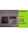
Position Display Units
for Milling Machines
11/ 95
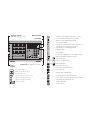
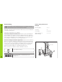
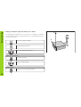
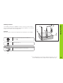
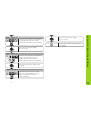
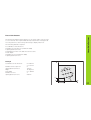
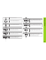
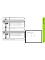
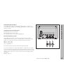
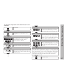
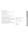
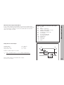
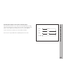
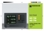
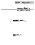
Position display
(ND 920: only two axes)
Message field
Distance-to-go display (traversing to zero)
For incremental dimensions (only with
distance-to-go and program input)
Input field
Tool compensation
SPEC
FCT
X
7
8
9
R+-
Y
4
5
6
PGM
Z
1
2
3
0
.
CL
HOLD
POS
MOD
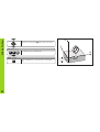
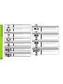
R+-
Call radius compensation for the current tool
SPEC
FCT
Special functions (probing functions,
hole patterns, rectangular pocket)
PGM
Program input
Select datum
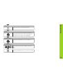
REF
R-
R+
PGM
GOTO
inch
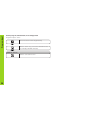
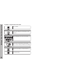
HEIDENHAIN
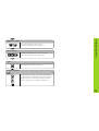
GOTO
X ••• Z
Status
display:
inch
Keyboard (ND 920 has no Z key)
Go directly to parameters or program steps
Page in program or parameter list/
select function
ENT
Select coordinate axis
0 ••• 9 Numerical input
Reset all axes to zero,
functions for Program Input
Inch display is active
Decimal point
Distance-to-go display is active
Change sign or parameter
PGM
Program input is active
REF
Reference marks have been crossed
R+
Radius compensation R+ is active
R–
Radius compensation R– is active
CL
Clear entry/cancel operating mode
HOLD
POS
Hold current position/output measured values
MOD
Datum point number
ENT
Select/deselect parameter list,
activate RS-232-C
Confirm entry
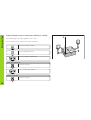
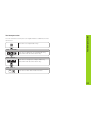
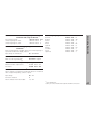
ND 920 (2 axes)
ND 960 (3 axes)
NDP 960 (3 axes, panel mount)
246 112 05
246 112 05
246 112 05
About this manual
This manual is divided into two parts:
Part I: Operating Instructions
• Fundamentals of positioning
• ND functions
Part II: Installation and Specifications
• Mounting the display unit on the machine
• Description of operating parameters
• Switching inputs, switching outputs
Part I: Operating Instructions
Fundamentals
4
Switch-On, Crossing Over the Reference Marks
9
Switching Between Operating Modes
9
Datum Setting
Datum setting with the tool
Datum setting with the KT Edge Finder
Resetting all axes to zero
10
11
13
18
Holding Positions
19
Tool Compensation
21
Moving the Axes with Distance-To-Go
22
Bolt Hole Circles and Bolt Circle Segments
24
Linear Hole Patterns
27
Rectangular Pocket
30
Scaling Factors
33
Program Input
34
Program Output over RS-232-C Interface
37
Error Messages
38
Part II: Installation and Specifications
39
Part I: Operating Instructions
This manual is for ND display units with the
following software numbers or higher:
3
Fundamentals
Fundamentals
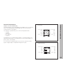
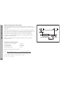
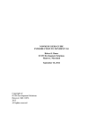
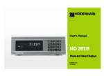
+Y
+Z
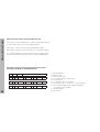
You can skip this chapter if you are already familiar with
coordinate systems, incremental and absolute dimensions,
nominal positions, actual positions and distance-to-go.
Graduation
+X
Coordinate system
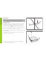
To describe the geometry of a workpiece, the Cartesian* coordinate
system is used. The Cartesian coordinate system consists of three
mutually perpendicular axes X, Y and Z. The point of intersection of
these axes is called the datum or origin of the coordinate system.
–X
Datum or
origin
Think of the axes as scales with divisions (usually in millimeters) which
allow us to fix points in space referenced to the datum.
–Z
–Y
To determine positions on a workpiece, the coordinate system is “laid”
onto the workpiece.
Z
The machine axes are parallel to the axes of the coordinate system.
The Z axis is normally the tool axis.
Y
X
4
*) Named in honor of the French mathematician and philosopher
René Descartes (1596 to 1650)
-125
-216,5
Fundamentals
250
250
0
-250
150
0
320
-150
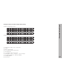
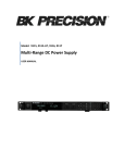
Relative
datums
0
750
900
950
700
450
0
Absolute
datum
325
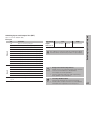
You can set up to 99 absolute datum points and store them in
nonvolatile memory.
1225
300±0,1
In the context of a numerical position display unit, datum setting means
bringing the workpiece and the tool into a defined position in relation to
each other and then setting the axis displays to the value which
corresponds to that position. This establishes a fixed relationship
between the actual positions of the axes and the displayed positions.
216,5
125
0
The workpiece drawing always indicates one absolute datum (the
datum for absolute dimensions). However, it may contain additional
relative datums.
125
216,5
The workpiece drawing is used as the basis for machining the
workpiece. To enable the dimensions in the drawing to be converted
into traverse distances of machine axes X, Y and Z, each drawing
dimension requires a datum or reference point on the workpiece (since
a position can only be defined in relationship to another position).
0
-250
-216,5
-125
Datum setting
5
Fundamentals
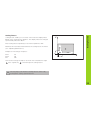
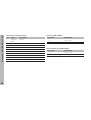
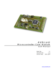
Absolute workpiece positions
Z
Each position on the workpiece is uniquely defined by its absolute
coordinates.
Example
Absolute coordinates of position 1 :
X = 10 mm
Y = 5 mm
Z = 0 mm
Y
X
If you are working according to a workpiece drawing with absolute
dimensions, you are moving the tool to the coordinates.
1
5
Relative workpiece positions
10
A position can also be defined relative to the previous nominal position.
The datum for the dimension is then located at the previous nominal
position. Such coordinates are termed incremental coordinates or
chain dimensions. Incremental coordinates are indicated by a preceding
I.
Example
Relative coordinate of position 2 referenced to
position 1 :
IX = 10 mm
IY = 10 mm
Z
Y
2
If you are working according to a workpiece drawing with incremental
dimensions, you are moving the tool by the dimensions.
10
1
Sign for incremental dimensioning
6
A relative dimension has a positive sign when the axis is moved in the
positive direction, and a negative sign when it is moved in the negative
direction.
1
10
5
10
X
Z
The position to which the tool is to move is called the nominal position
R
moment is called the actual position ( I ).
The distance from the nominal position to the actual position is called
S
I
( S ). The position at which the tool is actually located at any given
Y
the distance-to-go ( R ).
Sign for distance-to-go
X
Fundamentals
Nominal position, actual position and distance-to-go
When you are using the distance-to-go display, the nominal position
becomes the relative datum (display value 0). The distance-to-go is
therefore negative when you move in the positive axis direction, and
positive when you move in the negative axis direction.
7
Fundamentals
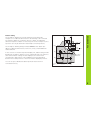
Position encoders
The position encoders on the machine convert the movements of the
machine axes into electrical signals. The ND display unit evaluates
these signals, determines the actual position of the machine axes and
displays the position as a numerical value.
Z
Workpiece
Y
If the power is interrupted, the relationship between the machine axis
positions and the calculated actual positions is lost. The reference
marks on the position encoders and the REF reference mark evaluation
feature enable the ND to quickly re-establish this relationship again
when the power is restored.
X
Position
encoder
Reference marks
The scales of the position encoders contain one or more reference
marks. When a reference mark is crossed over, a signal is generated
which identifies that position as a reference point (scale datum =
machine datum).
When this reference mark is crossed over, the ND's reference mark
evaluation feature (REF) restores the relationship between axis slide
positions and display values which you last defined by setting the
datum. If the linear encoders have distance-coded reference marks,
you only need to move the machine axes a maximum of 20 mm to do
this.
8
Scale in
linear encoder
Reference mark
Distance-coded
reference marks
0➨1
REF ?
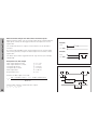
Turn on power (switch located on rear panel).
REF and decimal points in status display blink.
ENT ...CL
ENT
Press ENT before crossing reference marks
PASS OVER REF.
Cross over the reference marks in all axes (in any
sequence). Each axis display becomes active
when its reference mark is crossed over.
Crossing over the reference marks stores the last relationship between
axis slide positions and display values for all datum points (99 per axis)
in nonvolatile memory.
Note that if you choose not to cross over the reference marks (by
clearing the dialog REF ? with the CL key), this relationship will be
lost if the power is interrupted or when the unit is switched off.
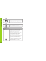
Switching Between Operating Modes
You can switch between the operating modes
Distance-To-Go, Special Functions, Program Input,
Set Tool Datum, Hold Position and Parameter Input at
any time simply by pressing another operating mode
key.
Switch-On, Crossing Over the Reference Marks
Switch-On, Crossing Over the Reference Marks
9
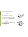
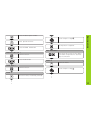
Datum Setting
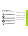
Datum setting with the tool
Datum Setting
If you want to save the datum points in nonvolatile memory,
you must first cross over the reference marks.
Example
Working plane
X / Y
Only after crossing over the reference marks can you set new datums
or activate existing ones.
Tool axis
Z
Tool radius
R = 5 mm
There are several ways to set datums:
Axis sequence for
datum setting
X–Y–Z
Touch the workpiece with the tool and then set the desired datum
(see example). You can also touch two edges and set the centerline
between them as a datum, or touch four points on a circle and set the
circle center as the datum. The tool data of the tool used for this are
automatically considered (see “Tool Compensation”).
Probe the workpiece with the edge finder and then set the desired
datum. You can also probe two edges and set the centerline between
them as a datum (see examples), or probe four points on a circle and
set the circle center as the datum. The display unit will automatically
consider the stylus radius and length if their values are entered in
parameters P25 and P26 (see “Operating Parameters”).
Z
R = 5 mm
After you have set a datum it can be activated as follows:
Y
Select datum setting.
X
1
2
DATUM NUMBER =
10
1
2
ENT
Enter the number of the datum point, for
example 12.
Touch workpiece edge 1 .
SPEC
FCT
Select special functions.
The X position is captured.
ENT
Select PROBING FUNCTION.
Datum Setting
Select the datum point number.
POS. MEASURED X =
PROBING FUNCTION ?
ENT
Confirm selection.
Select PROBE EDGE.
0
ENT
Enter the position value for the datum.
Tool radius compensation is automatically accounted for.
PROBE X
Y
Select the X axis.
PROBE EDGE ?
ENT
Confirm selection.
Touch workpiece edge 2 .
PROBE X
X
•
•
•
Select the X axis (if not already selected).
•
•
•
11
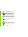
Datum Setting
The Y position is captured.
ENT
POS. MEASURED Y =
0
ENT
Enter the position value for the datum in
the Y axis. Tool radius compensation is
automatically considered.
PROBE Y
Select the Z axis.
Z
Touch the workpiece with the tool.
The Z position is captured.
ENT
POS. MEASURED Z =
0
12
ENT
SPEC
FCT
Enter the position value for the datum
in the Z axis.
When you have set the datum, leave
the probing function.
Your display unit offers the following probing functions:
PROBE EDGE
Set workpiece edge as datum
PROBE MIDPOINT
Set centerline between two workpiece edges
as datum
PROBE CIRCLE
Set a circle center as datum
Datum Setting
Datum setting with the KT edge finder
The probing functions can be accessed in operating mode SPEC FCT.
The HEIDENHAIN KT 120 edge finder only functions with
electrically conductive workpieces.
Before you can use the edge finder you must enter the stylus diameter
in parameter P25 and the stylus length in P26 (see “Operating Parameters”).
The stylus dimensions you enter are considered during all probing
operations.
PROBE EDGE and PROBE MIDPOINT are described on the following
pages.
The sequence for PROBE CIRCLE is similar; however, you must probe
four points before the circle center can be calculated. The circle center
can then be set as the new datum.
13
Datum Setting
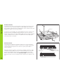
Probing a workpiece edge and setting it as a datum
Z
The probed edge is parallel to the Y axis. For all coordinates of a datum
you can probe workpiece edges and surfaces as described below and
set them as datums.
Select the datum number.
Y
X?
SPEC
FCT
Select special functions.
Select PROBING FUNCTION.
PROBING FUNCTION ?
ENT
Confirm selection.
Select PROBE EDGE.
PROBE EDGE ?
ENT
14
•
•
Confirm selection PROBE EDGE.
X
Select the X axis (if not already selected).
X
PROBE X
Move the edge finder towards the workpiece
edge until the LED in the edge finder lights up.
The position of the edge is now displayed.
Datum Setting
PROBE X
POS.MEASURED X =
Retract the edge finder from the workpiece.
POS.MEASURED X =
5
2
SPEC
FCT
ENT
Set the position value (for example 52) to this
edge.
Leave the probing functions, or select a new axis.
15
Datum Setting
Probing workpiece edges and setting the centerline as a datum
Z
The probed edges should be parallel to the Y axis.
You can follow these instructions for any centerlines.
Select the datum number.
Y
2
1
SPEC
FCT
Select special functions.
Select PROBING FUNCTION.
PROBING FUNCTION ?
ENT
Confirm selection.
Select PROBE MIDPOINT.
PROBE MIDPOINT ?
ENT
16
•
•
Confirm selection.
M
X?
X
Select X axis (if not already selected).
X
1. PROBE POS. X
Move the edge finder against workpiece edge 1
until the LED in the edge finder lights up.
The position of the edge is now displayed.
Datum Setting
1. PROBE POS. X
2. PROBE POS. X
Move the edge finder against workpiece edge 2
until the LED in the edge finder lights up.
The position of the edge is now displayed.
POS.MEASURED X =
2
6
SPEC
FCT
ENT
Enter the position value for the centerline
(for example 26).
Leave the probing functions, or select a new
axis.
17
Datum Setting
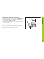
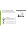
Resetting all axes to zero
To reset all axes to zero, simply press the key shown below. Note that
when you do this, the last actual position becomes the relative datum
and is not stored (incremental positioning). The status display then
shows “– –” instead of the datum number. Any datum points already
set remain in memory. You can activate these by entering the
corresponding datum point number.
This key resets all axis position displays to zero.
18
2
Z
Your display unit has the capability to hold or “freeze” position values.
The tool can be repositioned without affecting the display. You can then
assign a new value to the stored position.
Y
1
Example
Drill in the Z axis, measure the depth and set the datum to this depth.
X
Holding Positions
Holding Positions
Move to the desired position and drill in Z
direction 1 .
HOLD
POS
Hold the position.1)
KEEP Z POS. ?
Z
ENT
Store (hold) the position of the Z axis.
•
•
•
1)
The HOLD POS key may have a different function. See the
section "Measured value output with the HOLD POS key".
19
Holding Positions
Z
Retract tool to position 2 and measure position
ZT.
Y
SET POS. Z =
2
0
ENT
Set datum ZT (for example 20).
X
KEEP Z POS. ?
HOLD
POS
20
Leave HOLD POS or store position of another
axis.
ZT
You can enter the tool axis, the tool length and the tool diameter for the
current tool.
Press the tool compensation key.
TOOL DIAMETER =
2
0
Enter the tool diameter (for example 20 mm),
and confirm with the arrow down key.
Tool Compensation
Tool Compensation
TOOL LENGTH =
2 0 0
Enter the tool length (for example 200 mm),
and confirm with the arrow down key.
TOOL AXIS =
Z
Enter the tool axis and end the function.
21
NOML. VALUE X =
Y 2 0
R+-
Select the axis, enter the nominal value (for
example 20 mm), select radius compensation
R+ and confirm with ENT.
ENT
Move the axis until the display value is zero 1.
22
•
•
•
2
0
X
60
Select the distance-to-go function.
The ∆ symbol lights up.
4
30
Example: Milling a shoulder with distance-to-go
1
0
You can enter the absolute or the relative (incremental) coordinates in
the distance-to-go display. An active radius compensation will be
considered.
3
30
Normally, the display shows the actual position of the tool. However, it
is often more helpful to display the remaining distance to the nominal
position (the distance-to-go). You can then position simply by moving
the axis until the display value is zero.
Y
20
Moving the Axes with Distance-To-Go
Moving the Axes with the Distance-To-Go Display
X 3 0
R+-
ENT
Select the axis, enter the nominal value
(for example 30 mm), select radius
compensation R– and confirm with ENT.
Move the axis until the display
value is zero 2.
NOML. VALUE X =
3
Y
R+-
0
ENT
Select the axis, enter the nominal value
as an incremental dimension (for
example 30 mm), select radius
compensation R+ and confirm with ENT.
Move the axis until the display value
is zero 3.
Move the axis until the display
value is zero 4.
You can then switch off the distanceto-go display.
Moving the Axes with Distance-To-Go
NOML. VALUE Y =
NOML. VALUE IY =
X 6 0
ENT
•
•
•
R+-
Select the axis, enter the nominal
value (for example 60 mm), select
radius compensation R+ and
confirm with ENT.
23
Bolt Hole Circles
Bolt Hole Circles and Bolt Circle Segments
Your display unit enables you to quickly and easily drill bolt hole circles
and bolt hole circle segments. The required data is requested in the
message field.
Each hole can be moved to by traversing to display value zero. This
requires entry of the following data:
• Number of holes (maximum: 999)
• Circle center
• Circle radius
• Starting angle for first hole
• Angle step between the holes (only for circle segments)
• Hole depth
Example
Circle radius
Starting angle
Hole depth
8
X = 50 mm
Y = 50 mm
20 mm
30 degrees
Z = -5 mm
Y
30°
50
R2
0
Number of holes
Coordinates of the center
50
24
0
0
X
Select special functions.
CIRCLE CENTR X =
Select HOLE PATTERN.
X
5
0
Enter the X coordinate of the circle
center (for example 50 mm) and
confirm with the arrow down key.
HOLE PATTERN ?
ENT
Confirm selection.
CIRCLE CENTR Y
5
Y
0
Select FULL CIRCLE.
Enter the Y coordinate of the circle
center (for example 50 mm) and
confirm with the arrow down key.
RADIUS =
FULL CIRCLE ?
ENT
=
Bolt Hole Circles
SPEC
FCT
Confirm selection.
2
0
Enter the radius of the circle, (for
example 20 mm) and confirm with the
arrow down key.
NUMBER OF HOLES=
Enter the number of holes (e.g. 8) and
confirm with the arrow down key.
8
•
•
•
START ANGLE =
3
0
•
•
•
Enter the starting angle for the first
hole (for example 30 mm) and confirm
with the arrow down key.
25
Bolt Hole Circles
HOLE DEPTH =
5
Enter the hole depth (e.g. -5 mm) and confirm
with the arrow down key.
START ?
ENT
Start display of the hole positions.
FULL CIRCLE
GOTO
26
The distance-to-go mode is now active (∆ lights
up). Move to the individual hole positions by
traversing to display value zero. Holes can be
selected with the arrow keys or with the GOTO
key.
Linear Hole Patterns
Linear Hole Patterns
The linear hole pattern feature allows you to easily create rows of holes
to cover an area. The required data are requested in the message field.
You can position to each hole by traversing to display value zero.
The following data are required:
• Coordinates of the first hole
• Number of holes per row (maximum: 999)
• Spacing between holes
• Angle between the rows and the reference axis
• Hole depth
• Number of rows (maximum: 999)
• Spacing between rows
Example
12
16
9
5
1
15
8
7
6
2
3
4
20
15°
0
20
Number of holes per row
Spacing between holes
Angle
Hole depth
Number of rows
Spacing between rows
Y
X = 20 mm
Y = 15 mm
4
16 mm
15 degrees
Z = -30 mm
3
20 mm
0
Coordinates of the first hole
X
27
Linear Hole Patterns
Select special functions.
SPEC
FCT
HOLES PER ROW =
HOLE PATTERN ?
Enter the number of holes per row
(e.g. 4) and confirm with arrow down
key.
4
Go to HOLE PATTERN.
HOLE SPACING =
Select HOLE PATTERN.
ENT
1
6
Enter the spacing between holes in the
row and confirm with the arrow down
key.
Go to LINEAR PATTERN.
ANGLE =
LINEAR PATTERN ?
ENT
1ST HOLE X
2
1 5
28
•
•
Enter the angle (e.g. 15 degrees) and
confirm with the arrow down key.
=
Enter X coordinate of first hole (e.g. 20),
confirm with arrow down key.
0
1ST HOLE Y
1 5
Select LINEAR PATTERN.
HOLE DEPTH =
3
0
=
Enter Y coordinate of first hole (e.g. 15),
confirm with arrow down key.
•
•
•
Enter the hole depth (e.g. -30 mm) and
confirm with the arrow down key.
Enter the number of rows (e.g. 3)
and confirm with the arrow down key.
3
ROW SPACING =
2
Enter the spacing between rows (e.g. 20)
and confirm with the arrow down key.
0
START ?
Linear Hole Patterns
NUMBER OF ROWS =
=
ENT
Start display of the hole positions.
LINEAR PATTERN
Distance-to-go mode is now active (∆ symbol is
on). Move to the individual holes by traversing to
display value zero. The holes can be selected
with the arrow keys or with the GOTO key.
GOTO
29
Y
Your ND display unit facilitates milling rectangular pockets. The required
data are requested in the message field.
1
26
45
Machining begins in the center of the pocket. Using the distance-to-go
display, the pocket is machined outwards in a spiral pattern until the
final dimension is reached. The last step is finishing.
The infeed depends on the tool radius and is calculated automatically.
The following data must be entered to completely describe a
rectangular pocket:
• The two side lengths
• Depth of the pocket
• Coordinates of the starting position (pocket center)
• Finishing allowance
• Milling direction (climb/up-cut)
Example
Dimensions of the pocket
Depth
Center point coordinates
Starting position
Finishing allowance
Milling direction
X = 60 mm
Y = 45 mm
Z = -15 mm
X = 40 mm
Y = 26 mm
Z=
2 mm
1 mm
climb
0
40
There are two conditions under which machining cannot be started:
tool diameter = 0, or tool diameter ≥ side length – 2 × finishing allowance.
These conditions will generate the error message TOOL ERROR.
You move to each position by traversing to display value zero.
30
60
0
Rectangular Pocket
Rectangular Pocket
Step 7
0.000
Step 2
0.000
X
Select special functions.
POCKET CENTER X =
Go to RECTANGULAR POCKET.
RECTANG.POCKET ?
ENT
SIDE LENGTH X
6 0
Select RECTANGULAR POCKET.
=
Enter side length in X direction (e.g. 60),
confirm with arrow down key.
4 0
Enter X coordinate of pocket center
(e.g. 40) and confirm with arrow down
key.
POCKET CENTER Y =
2 6
Enter Y coordinate of pocket center
(e.g. 26) and confirm with arrow down
key.
Rectangular Pocket
SPEC
FCT
STARTING POS. Z =
Enter starting position for tool axis
(e.g. 2) and confirm with arrow down
key.
2
SIDE LENGTH Y =
4 5
Enter side length in Y direction (e.g. 45),
confirm with arrow down key.
ALLOWANCE =
Enter finishing allowance for last
machining step (e.g. 1 mm) and
confirm with arrow down key.
1
DEPTH Z =
Enter the pocket depth (e.g. -15),
confirm with arrow down key.
1 5
•
•
•
•
•
•
31
Rectangular Pocket
DOWN-CUT
Use the minus key to select down-cut
milling (climb milling) or up-cut milling,
and confirm with the arrow down key.
START ?
ENT
Start rectangular pocket milling.
RECTANG.POCKET
CL
32
Distance-to-go mode is now active
(∆ symbol is on). You move to the
individual clear-out positions by
traversing to display value zero. When
you reach a position, the display
automatically shows the next step
until machining is completed.
When you have cleared out the pocket
at one level, the display returns to
block 0 so you can clear out the next
level.
To interrupt machining, press CL. This
returns the display to the dialog
START ?.
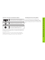
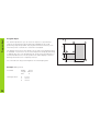
Scaling Factors
Scaling Factors
Y
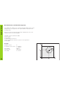
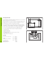
Scaling factors enable you to increase or decrease the display values
based on the actual traverse distance. The display values are changed
symmetrically about the datum.
Parameter P11 activates and deactivates the scaling factors in all axes
(see “Operating Parameters”).
* 3.0
Enter scaling factors separately for each axis in parameter P12.
Example for increasing a workpiece:
1
3.5
3.0
ON
* 3.5
0
X
0
P12.1
P12.2
P11
2
This results in a larger workpiece as shown in the illustration at right:
1 is the original size, 2 is with axis-specific scaling factors.
The only way to tell whether a scaling factor is active is by
looking at the setting of parameter P11.
33
Y
The display unit goes into the distance-to-go mode when Program Input
is activated. You can move to the entered positions simply by traversing
to display value zero. The program blocks can be entered in absolute or
incremental dimensions. The ∆ symbol in the status display continues
blinking until the block is completely entered.
3
4
30
For small-lot production you can enter the sequence of positioning
steps in the operating mode Program Input (PGM key). Up to 99
positioning steps are possible. The program remains in memory even
when the power is turned off or otherwise interrupted.
1
2
20
Program Input
Program Input
0
34
Tool data:
Radius
Length
Axis
Starting position:
X
Y
Z
6 mm
50 mm
Z
-6 mm
0 mm
0 mm
30
0
Example: Milling a step
60
X
You can start from any positioning block in a finished program.
Program Input
Select program input.
PGM
AXIS ?
2
Y
0
R+-
Select the axis, enter the nominal value in
absolute dimensions (for example 20 mm),
enter radius compensation R+ and confirm with
ENT if you wish to position immediately.
ENT
Select the next block.
AXIS ?
Finished program:
X
3
R+-
0
Select the axis, enter the nominal value in
absolute dimensions (for example 30 mm),
enter radius compensation R– and confirm with
ENT if you wish to position immediately.
1
2
3
4
Y
X
IY
X
+20
+30
+30
+60
R+
R–
R+
R+
ENT
Enter further blocks in the same manner.
35
Program Input
Delete program, delete block, insert empty block
Program Input is active.
Select functions for deleting/inserting.
With the arrow keys, select the desired function
(for example, DELETE BLOCK).
DELETE BLOCK ?
ENT
36
Start the selected function.
Programs in memory can be output over the RS-232-C/V.24 interface
(see following sequence). Programs can also be downloaded.
Select program input.
PGM
Select RS-232-C/V.24 functions.
MOD
Select program output to FE 401 floppy disk
unit.
PGM OUTPUT FE ?
Confirm program output to FE 401 floppy disk
unit.
ENT
Programs can be transferred to the FE 401 floppy
disk unit, a PC or a printer.
The RS-232-C/V.24 setting for a printer is stored
under EXT (standard data interface). The RS-232-C/
V.24 setting for the FE 401 or a PC is stored under
FE. A question in the message field asks which
interface you wish to activate.
To transfer a program stored in your ND you must
assign the program a number. To load this program
again, you must call it with the same program
number.
A special software package is available from
HEIDENHAIN for data transfer to a PC. This software
must be installed on the PC.
Parameter P50 specifies the baud rate (see
“Operating Parameters”).
For additional information, see the chapter
“RS-232-C/V.24 Interface.”
PGM NUMBER ?
4
5
ENT
Program Output Over RS-232-C Interface
Program Output over RS-232-C Interface
Key in the program number.
OUTPUT ACTIVE
CL
You can interrupt data transfer with the CL key.
37
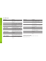
Error Messages
38
Error Messages
Message
CALL IS TOO FAST
Problem
Two commands for measured
value output occurred too close
together.
AMPL. X TOO LOW The encoder signal is too weak.
The scale may be contaminated.
PROBING ERROR
The axis must move at least 6 µm
before probing.
DSR SIG. MISSING
The attached device is not
sending a DSR signal..
INPUT ERROR
The entered value is not within
the permissible input range.
ERROR: REF. X
The spacing of the reference
marks as defined in P43 is not
the same as the actual spacing.
FORMAT ERROR
Data format, baud rate, etc., do
not agree.
FRQ. EXCEEDED X The input frequency for this encoder
input is too high. This can occur
when the scale is moved too fast.
COMP. DELETED
Compensation values for nonlinear axis error compensation
erased.
Message
OFFSET DELETED
PARAM. ERASED
PGM ERASED
PGM TOO LARGE
PRESET ERASED
KEY W/O FUNCTION
TEMP. EXCEEDED
Problem
Offset compensation values for
encoder signals erased.
Check the operating parameters.
If this error recurs, contact your
service agency.
The program has been deleted.
If this error recurs, contact your
service agency.
The maximum program length is
99 blocks.
The datum points have been
erased. If this error recurs, contact
your service agency.
This key currently has no
function.
The temperature of the ND is too
high.
To clear error messages
When you have removed the cause of the error,
➤ press the CL key.
Items Delivered
40
Connections on Rear Panel
41
Mounting
42
Power Connection
42
Connecting the Encoders
43
Operating Parameters
44
Linear Encoders
Setting the display step
Display step, signal period and subdivision
Compatible HEIDENHAIN linear encoders
48
48
48
49
Multipoint Axis Error Compensation
50
RS-232-C/V.24 Interface
(option with ND 920/ND 960)
Pin layout X 31 (RS-232-C/V.24)
53
54
Measured Value Output
55
Switching Inputs and Outputs X41 (EXT)
(option with ND 920/ND 960)
Pin layout
Switching ranges
Resetting the display to zero with an external signal
61
Pin Layout X10 for Edge Finder
64
Specifications
65
61
62
63
Part II: Installation and Specifications
Part II: Installation and
Specifications
39
Items Delivered
Items Delivered
• ND 920 for two axes
or
• ND 960 for three axes
or
• NDP 960 for three axes
• Power connector
Id.-Nr. 257 811 01
• User's Manual
Optional Accessories
• Tilting base
Id.-Nr. 281 619 01
• KT 120 Edge Finder
Id.-Nr. 276 416 01
• KT 130 Edge Finder
Id.-Nr. 283 273 01
• Connector (female), 25-pin, for D-sub connection X41
Id.-Nr. 249 154 ZY
• Data interface cable, 25-pin, length 3 m
Id.-Nr. 274 545 01
• Connector (male), 25-pin, for D-sub connection X31
Id.-Nr. 245 739 ZY
40
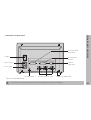
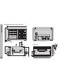
Switching inputs
and outputs
ID label
RS-232-C/V.24
interface
X41(EXT) 1)
X31(V.24 RS-232-C) 1)
X10
Input for
edge finder
Power switch
X3
X2
Connections on Rear Panel
Connections on Rear Panel
X1
Power input
Ground terminal
1)
Encoder inputs X1 to X3
Rubber feet (M4 thread)
Option with ND 920/ND 960
Connections X1, X2, X3, X31 and X41 are not shock hazardous according to EN 50178.
41
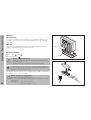
Mounting / Power Connection
Mounting
ND 920/ND 960
To mount the display unit on a support, use the M4 threaded holes in
the rubber feet. You can also mount the display unit on the optional
tilting base.
NDP 960
This unit is designed for installation in an operating panel using the
supplied mounting frame (see “Dimensions”).
Power Connection
Power leads: L and N
Protective ground:
• Danger of electrical shock!
Connect a protective ground. This connection must never
be interrupted.
• Unplug the power cord before opening the housing.
To increase the noise immunity, connect the ground terminal
on the rear panel to the central ground point of the machine.
(Minimum cross-section: 6 mm2)
The display unit will operate over a voltage range of 100 V to 240 V AC.
A voltage selector is not necessary.
42
HE
ID
EN
HA
IN
Tilting base
Danger to internal components!
Use only original replacement fuses.
Two line fuses and a fuse for the switching outputs are inside
the housing.
Fuse types:
Line: F 2.5 A 250 V
Switching outputs: F 1 A
Support
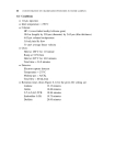
Your display unit will accept all HEIDENHAIN linear encoders with
sinusoidal output signals (11 to 40 µApp) and distance-coded or single
reference marks.
Assignment of the encoder inputs
Encoder input X1 is for the X axis
Encoder input X2 is for the Y axis
Encoder input X3 is for the Z axis (ND 960 only)
X41(EXT) 1)
X31(V.24 RS-232-C) 1)
X10
X3
X2
X1
Z
Y
X
Encoder monitoring system
Your display unit features a monitoring system for checking the
amplitude and frequency of the encoder signals. If it detects a faulty
signal, one of the following error messages will be generated:
Connecting the Encoders
Connecting the Encoders
AMPL.X TOOL LOW
AMPL.X TOO HIGH
FRQ. EXCEEDED X
Encoder monitoring can be activated with parameter P45.
If you are using linear encoders with distance-coded reference marks,
the encoder monitoring system also checks whether the spacing of the
reference marks as defined in parameter P43 is the same as the actual
spacing on the scales. If it is not, the following error message will be
generated:
ERROR: REF. X
1)
Option with ND 920/ND 960
43
Operating Parameters
Operating Parameters
Operating parameters allow you to modify the operating
characteristics of your display unit and define the evaluation of
the encoder signals. Operating parameters that can be
changed by the user are called user parameters, and can be
accessed with the MOD key and the dialog PARAMETER
(user parameters are identified as such in the parameter list).
The full range of parameters can only be accessed through
CODE NUMBER.
To access the operating parameters
➤ Press the MOD key
➤ Confirm with ENT to access the user parameters, or select
the dialog for entering the code number (95148) with the
arrow down key to be able to change all operating
parameters.
To page through the operating parameters
Operating parameters are designated by the letter P and a
number. Example: P11. The parameter designation is shown
in the input field as you press the arrow keys to select a
parameter. The parameter setting is displayed in the message
field.
➤ Page forwards by pressing the arrow down key.
➤ Page backwards by pressing the arrow up key.
➤ Go directly to an operating parameter by pressing GOTO,
keying in the parameter number and then pressing ENT.
Some operating parameters have separate values for each
axis. Such parameters have an additional index number from
1 to 3 (ND 920: 1 to 2).
To change parameter settings
Example
To correct an entry
P12.1 scaling factor, X axis
P12.2 scaling factor, Y axis
P12.3 scaling factor, Z axis (ND960/NDP960 only)
Operating parameters P60 and P61 (definition of the switching
ranges) have an index from 0 to 7.
The operating parameters are preset before the unit leaves
the factory. These factory settings are indicated in the
parameter list in boldface type.
44
Entering and changing operating parameters
➤ Press the minus key or enter the value and confirm
with the ENT key.
➤ Press CL. This restores the old value.
To leave the operating parameters
➤ Press MOD again.
P1
Unit of measurement 1)
Display in millimeters
Display in inches
P3.1 to P3.3
mm
inch
Radius/diameter display 1)
Display position value as radius
Display position value as diameter
RADIUS DISPLAY X
DIAM. DISPLAY X
P12.1 to P12.3
DISPLAY: ACTUAL
Display is stopped during the
latching process
DISPLAY: HOLD
Display is stopped but is updated
by each latching process
DISPLAY: STOP
P25 Probe diameter 1)
Input range (millimeters):
Factory setting
P11 Activate scaling factor 1)
Scaling factor active
Not active
Display is not stopped during
the latching process
SCALING ON
SCALING OFF
Enter scaling factor 1)
P26 Probe length 1)
Input range (millimeters):
Enter a scaling factor separately for each axis:
Entry value > 1: workpiece will “grow”
Entry value = 1: workpiece will remain the same size
Entry value < 1: workpiece will “shrink”
Input range:
0.100000 to 9.999999
Factory setting:
1.000000
P30.1 to P30.3
P23 Display of position values for measured
value output 1) 2)
P31.1 to P31.3
When a measured value is output through pulse, contact or
CTRL B it is first latched (stored in a buffer) and then sent over
the RS-232-C interface. Parameter P23 selects the display
mode for the latching process.
0.000 to 999.999
6
Operating Parameters
List of operating parameters
0.000 to 999.999
Counting direction
Positive counting direction with
positive direction of traverse
COUNTR. X : POS.
Negative counting direction with
positive direction of traverse
COUNTR. X : NEG.
Signal period of encoder
2 µm / 4 µm / 10 µm / 20 µm / 40 µm
100 µm / 200 µm / 12 800 µm
P32.1 to P32.3
Subdivision of the encoder signals
128 / 100 / 80 / 64 / 50 / 40 / 20 / 10 / 5 / 4 / 2 / 1 /
0.5 / 0.4 / 0.2 / 0.1
1)
2)
User parameter
Only on units with RS-232-C/V.24 and EXT connection
45
Operating Parameters
P40.1 to P40.3
Select type of axis error compensation
No axis error compensation
Linear error compensation active,
multipoint error comp. not active
AXIS COMP X LIN
Multipoint error compensation active,
linear error compensation not active AXIS COMP X F(a)
P41.1 to P41.3
Linear axis error compensation
Input range (µm):
−99999 to +99999
Factory setting:
0
Example
Displayed length Ld = 620.000 mm
Actual length (as determined for example with
the VM 101 from HEIDENHAIN)
La = 619.876 mm
Difference DL = La – Ld = –124 µm
Compensation factor k:
k = DL/Ld = –124 µm/0.62 m = –200 [µm/m]
P43.1 to P43.3
P44.1 to P44.3
Encoder monitoring
Amplitude and frequency
monitoring active
ALARM X ON
Not active
ALARM X OFF
P48.1 to P48.3 Activate axis display
Axis display active
Not active
0
500
1000
2000
5000
REF. MODE X ON
REF. MODE X OFF
2)
For output of the measured value, an axis designation can be
defined with the number of the ASCII character. The axis
designation is output together with the measured value.
Input range:
Measured value output disabled
ASCII character from ASCII table
Factory setting:
P50
Baud rate
0 to 127
0
1 to 127
P49.1
88
P49.2
89
P49.3
90
1) 2)
110 / 150 / 300 / 600 / 1200 / 2400 / 4800 / 9600 /
19 200 / 38 400
P51 Blank lines for measured value output
Reference mark evaluation
Reference mark evaluation active
Not active
AXIS DISPL.X ON
AXIS DISPL.X OFF
P49.1 to P49.3 Axis designation, measured value output
Reference marks
One reference mark
Distance-coded with 500 x SP
Distance-coded with 1000 x SP
Distance-coded with 2000 x SP
Distance-coded with 5000 x SP
(SP = signal period)
46
AXIS COMP X OFF
P45.1 to P45.3
Input range:
Factory setting
1)
2)
1) 2)
0 to 99
1
User parameter
Only on units with RS-232-C/V.24 and EXT connection
No switching range
Switching range for X axis
Switching range for Y axis
Switching range for Z axis
P61.0 to P61.7
SWITCH
SWITCH
SWITCH
SWITCH
OUT.0
OUT.0
OUT.0
OUT.0
OFF
X
Y
Z
Define switching range for EXT
connection 2)
Enter switching point (= display value): the switching range is
symmetrical about the display value 0.
Input range (in millimeters):
0 to 99 999.999
P81.1 to P81.3
German
English
French
Italian
Dutch
Spanish
Danish
Swedish
Czech
Japanese
DIALOG
DIALOG
DIALOG
DIALOG
DIALOG
DIALOG
DIALOG
DIALOG
DIALOG
DIALOG
LANG.
LANG.
LANG.
LANG.
LANG.
LANG.
LANG.
LANG.
LANG.
LANG.
D
GB
F
I
NL
E
DK
S
CZ
J
Operating Parameters
P98 Dialog language 1)
P60.0 to P60.7 Activate switching range for EXT
connection and assign to the axes 2)
Encoder
Max. encoder signal 16 µApp
Max. encoder signal 40 µApp
ENCODER X 16µA
ENCODER X 40µA
P96 Measured value output with probing 2)
Measured value output active
Not active
PROBE RS232 ON
PROBE RS232 OFF
P97 Code for measured values 2)
ASCII character for identifying measured values for measured
value output with probing, contact or pulse
Input range:
No ASCII character
ASCII character from ASCII table
0 to 127
0
1 to 127
1)
2)
User parameter
Only on units with RS-232-C/V.24 and EXT connection
47
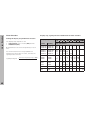
Linear Encoders
Display step, signal period and subdivision for linear encoders
Linear Encoders
Setting the display step with linear encoders
The display step depends on the
• signal period of the encoder (P31) and the
• subdivision (P32).
Both parameters are entered separately for each
axis.
For linear measurement using nut/ballscrew
arrangements and rotary encoders, calculate the
signal period as follows:
Signal period [µm] =
Drivescrew pitch [mm] x 1000
Line count
48
Display step
[mm]
[inches]
0.000 02 0.000 001
0.000 05 0.000 002
P31: Signal period [µm]
2
4
20 40
10
100 200 12 800
P32: Subdivision
100
40
–
80
–
–
–
–
–
–
–
–
–
–
–
–
100
–
50 100
20 40
–
–
80
–
–
–
–
–
–
–
–
–
0.000 1
0.000 2
0.000 5
0.000 005
0.000 01
0.000 02
20
10
4
40
20
8
0.001
0.002
0.005
0.000 05
0.000 1
0.000 2
2
1
0.4
4
2
0.8
10
5
2
20
10
4
40
20
8
100
50
20
–
100
40
–
–
–
0.01
0.02
0.05
0.000 5
0.001
0.002
0.2
–
–
0.4
–
–
1
2
0.5
1
0.2 0.4
4
2
0.8
10
5
2
20
10
4
–
–
–
0.1
0.005
–
–
0.1 0.2
0.4
1
2
128
0.2
0.01
–
–
–
–
–
64
–
–
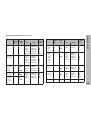
Encoder
LIP 40x
Signal
period
P31
Ref.
marks
P43
2
0
Display step
mm
inches
Subdivision
P32
0.001
0.000 05
0.000 5
0.000 02
0.000 2
0.000 01
0.000 1
0.000 005
0.000 05 0.000 002
0.000 02 0.000 001
2
4
10
20
40
100
LIP 101 A
LIP 101 R
4
0
0.001
0.000 05
0.000 5
0.000 02
0.000 2
0.000 01
0.000 1
0.000 005
0.000 05 0.000 002
4
8
20
40
80
LIF 101 R
LIF 101 C
LF 401
LF 401 C
4
0
5000
0
5000
0.001
0.000 5
0.000 2
0.000 1
0.000 05
0.000 02
0.000 01
0.000 005
4
8
20
40
LID xxx
LID xxx C
LS 103
LS 103 C
LS 405
LS 405 C
ULS/10
10
0
2000
0
or
1000
0.001
0.000 5
0.000 2
0.000 1
0.000 05
0.000 02
0.000 01
0.000 005
10
20
50
100
10
Encoder
Signal
period
P31
Ref.
marks
P43
LS 303
LS 303 C
LS 603
LS 603 C
20
0
or
1000
0.01
0.005
0.000 5
0.000 2
2
4
LS 106
LS 106 C
LS 406
LS 406 C
LS 706
LS 706 C
ULS/20
20
0
or
1000
0.01
0.005
0.002
0.001
0.000 5
0.000 5
0.000 2
0.000 1
0.000 05
0.000 02
2
4
10
20
40
LIDA 10x
LB 302
40
0
or
2000
0.002
0.001
0.000 5
0.000 1
0.000 05
0.000 02
20
40
80
LIDA 2xx
LB 3xx
LB 3xx C
100
0
0.01
0.005
0.002
0.001
0.000 5
0.000 2
0.000 1
0.000 05
10
20
50
100
LIM 102
12 800
0.1
0.005
128
1000
0
Display step
mm
inches
Subdivision
P32
Linear Encoders
Compatible HEIDENHAIN linear encoders
49
Multipoint Axis Error Compensation
Multipoint Axis Error Compensation
If you want to use the multipoint axis error
compensation feature, you must
• activate this feature with operating parameter P40
(see "Operating Parameters")
• traverse the reference marks after switching on the
display unit
• enter compensation value table
Entries in the compensation value table
•
Axis to be corrected:
X, Y or Z (Z axis only with
ND 960 or NDP 960)
•
Axis causing the error:
X, Y or Z (Z axis only with
ND 960 or NDP 960)
•
Datum for the axis to be corrected:
Here you enter the point starting at which the axis with
error is to be corrected. This point indicates the absolute
distance to the reference point.
Your machine may have a non-linear axis error due to factors
such as axis sag or drivescrew errors. Such deviations are
usually measured with a comparator measuring system (such
as the HEIDENHAIN VM 101).
For example, you can determine the screw pitch error X=F(X)
for the X axis.
Do not change the datum point after measuring the
axis error and before entering the axis error into the
compensation table.
•
Spacing of the compensation points
The spacing of the compensation points is expressed as
2x [µm].
Enter the value of the exponent x into the compensation
value table.
Minimum input value: 6 (= 0.064 mm)
Maximum input value: 20 (= 1048.576 mm)
Example: 600 mm traverse and 35 compensation points:
results in 17.143 mm spacing between points.
Nearest power of two: 214 [µm] = 16.384 mm
Entry in compensation value table: 14
•
Compensation value
You enter the measured compensation value (in
millimeters) for the displayed compensation point.
Compensation point 0 always has the value 0 and
cannot be changed.
An axis can only be corrected in relation to one axis that has
an error. In each axis, a compensation value table with
64 compensation values can be generated. You can select the
compensation value table with the MOD key and the dialog
"CODE NUMBER".
All necessary entries for multipoint error compensation are
requested in dialogs.
50
Press MOD.
MOD
DATUM X =
2
7
PARAMETER ?
Select dialog for entering the code
number.
POINT SPACING X=
1
0
CODE NUMBER ?
1 0 5 2
9 6
ENT
Enter 105296 and confirm with ENT.
The ND displays the REF values
(reference point = datum).
X
COMP. AXIS = X
0
Select the axis to be corrected (e.g. X),
and confirm with the arrow down key.
X
X
= FKT (X )
Enter the axis causing the error (e.g. X)
(screw pitch error), and confirm with the
arrow down key.
X
•
•
•
Enter the spacing of the compensation
points on the axis to be corrected, for
example 210 µm (equals 1024 mm) and
confirm with the arrow down key.
27.000 X =
0
X
Enter the active datum for the error on
the axis to be corrected (e.g. 27 mm)
and confirm with the arrow down key.
1
Select compensation point no. 1, enter
the associated compensation value (e.g.
0.01 mm) and confirm with the arrow
down key.
Multipoint Axis Error Compensation
To select the compensation value table and enter an axis
correction
28.024 X =
Enter all further compensation points. If you press and hold
the arrow down key when selecting the next compensation
point, the number of the current compensation point will be
displayed in the input line. You can go directly to compensation points by using the GOTO key and entering the
corresponding number.
MOD
Conclude entry.
51
Multipoint Axis Error Compensation
To delete a compensation value table
Press MOD.
MOD
PARAMETER ?
Select the dialog for entering the code
number.
CODE NUMBER ?
1 0 5 2
9 6
Enter 105296 and confirm with ENT.
ENT
COMP. AXIS = X
Select the compensation value table
(e.g., for the Z axis), and delete the table.
Z
DEL.COMP.AXIS Z?
ENT
MOD
52
Confirm with ENT, or cancel with CL.
Conclude entry.
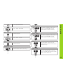
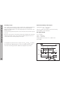
Full wiring
The data interface on your ND display unit enables you to use a printer,
a PC or the HEIDENHAIN FE 401 floppy disk unit for transferring
measured values or programs.
CHASSIS GND
1
1 CHASSIS GND
TXD
2
2
TXD
RXD
RTS
CTS
3
4
5
3
4
5
RXD
RTS
CTS
DSR
GND
6
7
6
DSR
7 SIGNAL GND
The interface is permanently set to the following data format:
1 start bit
7 data bits
Even parity bit
2 stop bits
SIGNAL
DTR 20
20
DTR
The baud rate is set with parameter P50. See “Program Output over
RS-232-C/V.24 Interface” for instructions on how to start output to a
printer, a PC or the FE 401.
For connection to peripheral devices you can use either full wiring
(figure at upper right) or simplified wiring (below right).
RS-232-C/V.24 Interface
RS-232-C/V.24 Interface
(Option with ND 920/ND 960)
Simplified wiring
CHASSIS GND
1
1 CHASSIS GND
TXD
2
2
TXD
RXD
RTS
CTS
3
4
5
3
4
5
RXD
RTS
CTS
DSR
GND
6
7
6
DSR
7 SIGNAL GND
SIGNAL
DTR 20
20
DTR
53
Pin Layout X31 (RS-232-C/V.24)
54
Pin layout X31 (RS-232-C/V.24)
Signal
Assignment
1
Pin
CHASSIS
GND
Chassis
2
TXD
Transmitted data
3
RXD
Received data
4
RTS
Request to send
5
CTS
Clear to send
6
DSR
Data set ready
7
SIGN. GND Signal ground
8...19
20
21..25
−
DTR
−
Not assigned
Data terminal ready
Not assigned
Levels for TXD and RXD
Logic level
Voltage level
"1"
–3 V to –15 V
"0"
+3 V to +15 V
Levels for RTS, CTS, DSR and DTR
Logic level
Voltage level
"1"
+3 V to +15 V
"0"
–3 V to –15 V
Measured Value Output
Measured Value Output
Measured values can be output over the RS-232-C/V.24 interface. This
can be done with the following functions:
Probing with the KT Edge Finder
“Contact” input on X41
“Pulse” input on X41
CTRL B over the RS-232-C interface
Measured value output with the HOLD POS key.
Parameter P23 influences the display mode for measured value output.
It is not effective, however, for output from probing.
Code letters with the measured value
Parameter P97 allows you to select a code letter to be output together
with the measured value when using Probe, Contact or Pulse. The
decimal number you enter in the parameter is the ASCII character
number in the ASCII table. If you enter 0, no code letter will be output.
The code letter enables you to recognize whether the measured value
was generated with CTRL B or with an external signal.
Axis designation for measured value output
Parameter P49 allows you to enter an axis designation for each
measured value that is output. The decimal number you enter in the
parameter is the ASCII character number in the ASCII table. If you enter
0, no axis designation will be output.
Example of measured value output:
Parameter settings:
P49.1
P49.2
P49.3
P51
P97
=
=
=
=
=
88
89
90
0
69
(“X”)
(“Y”)
(“Z”)
(no blank lines)
(“E”)
Output:
E (CR)(LF)
X=...(CR)(LF)
Y=...(CR)(LF)
Z=...(CR)(LF)
55
Measured Value Output
Measured value output when probing
Parameter P96 allows you to activate measured value output when
probing with the KT edge finder. The edge finder is connected to D-sub
input X10.
Whenever the Probe Edge function is used, your display unit outputs
the position of the edge in the selected axis and the actual positions of
the other axes over the TXD line of the RS-232-C/V.24 interface.
Whenever the Probe Midpoint function is used, your display unit
outputs the calculated midpoint in the selected axis and the actual
positions of the other axes.
Measured value output with CTRL B is inhibited when a probing
function is active.
Delay times with data output
Duration of the latch signal:
Storage delay:
Data output after:
Regeneration time:
te ≥ 4 µs
t1 ≤ 4.5 ms
t2 ≤ 50 ms
t3 ≥ 0
Duration of data output in seconds:
tD =
176 x number of axes + 11 x number of blank lines
Baud rate
Next possible signal for measured value output:
tE = t1 + t2 + tD + t3 [s]
56
te
te
t1
t2
t3
tD
Example: Probe Edge, X axis
P
R
X
:
+
5854
.
2504
R
<CR>
<LF>
Y
:
−
1012
.
8660
R
<CR>
<LF>
Z
:
+
8590
.
3042
R
<CR>
<LF>
?
Example: Probe Midpoint, X axis
C
➀
➁
➂
➃
➄
➅
➆
➇
➈
➉
L
X
:
+
3476
.
2504
R
<CR>
<LF>
Y
:
−
1012
.
8660
R
<CR>
<LF>
Z
:
+
8590
.
3042
R
<CR>
<LF>
➀
➁
➂
➃
➄
➅
➇
➈
➉
➆
Probed axis <PR>, <CL> / other axes
Colon
Plus or minus sign
2 to 7 places before the decimal
Decimal point
1 to 6 places after the decimal
Unit: blank = mm, " = inches, ? = error message
R = radius display, D = diameter display
Carriage Return
Line Feed
Measured Value Output
Example of measured value output when probing
57
Measured Value Output
Measured value output over the Contact and Pulse inputs
Measured value output over the Contact input (pin 9 on X41) and Pulse
input (pin 8 on X41) can be triggered when these inputs are closed
against 0 V.
The measured values are output over the TXD line of the RS-232-C
interface.
EXT(X41)
Pin 9
Pin 1(0V)
A commercially available switch can be attached to the Contact input.
This switch generates a signal for data output when it makes contact
against 0 V.
EXT(X41)
The Pulse input can be triggered with TTL logic devices (for example,
SN74LSXX).
Pin 1(0V)
Pin 8
Delay times for data output
Latch signal duration: Pulse
Latch signal duration: Contact
Storage delay: Pulse
Storage delay: Contact
Data output after
Regeneration time
te
te
t1
t1
t2
t3
≥
≥
≤
≤
≤
≥
1.2 µs
7 ms
0.8 µs
4.5 ms
30 ms
0
Duration of data output in seconds:
tD =
te
te
t1
176 x number of axes + 11 x number of blank lines
Baud rate
t2
t3
Next possible signal for measured value output:
tE = t1 + t2 + tD + t3 [s]
58
tD
If the control character STX (CTRL B) is received over the RS-232-C
interface, the measured value referenced to this time point will be sent
over the interface. CTRL B is received over RXD and the measured
values are output over TXD.
BASIC program for measured value output:
10
L%=48
20
CLS
30
PRINT "V.24/RS232"
40
OPEN "COM1:9600,E,7" AS#1
50
PRINT #1, CHR$ (2);
60
IF INKEY$<>""THEN 130
70
C%=LOC(1)
80
IF C%<L%THEN 60
90
X$=INPUT$(L%,#1)
100 LOCATE 9,1
110 PRINT X$;
120 GOTO 50
130 END
Measured Value Output
Measured value output with CTRL B
Delay times for data output
t1 ≤ 0.5 ms
t2 ≤ 30 ms
t3 ≥ 0 ms
Storage delay
Data output after
Regeneration time
Duration of data output in seconds:
tD =
176 x number of axes + 11 x number of blank lines
CTRLB
CTRLB
t1
t2
t3
Baud rate
Next possible signal for measured value output:
tE = t1 +t2 + tD + t3 [s]
tD
59
Measured Value Output
Measured value output with the HOLD POS key
The function of the HOLD POS key can be changed by entering
a code number. Enter the code number 246 522.
Press the "–" key to select the dialog HOLD POS or PRT.
Press ENT to save the selected function in non-volatile storage.
If you selected PRT, the position values will be output through
the RS-232-C/V.24 interface whenever you press HOLD POS.
Example of measured value output with Contact input,
Pulse input, CTRL B, or the HOLD POS key
60
E
<CR>
<LF>
X
=
+
5854
.
2504
R
<CR>
<LF>
Y
=
-
1012
.
8660
R
<CR>
<LF>
Z
=
+
8590
.
3042
R
<CR>
<LF>
➀
➁
➂
➃
➄
➅
➇
➈
➉
➆
➀
➁
➂
➃
➄
➅
➆
➇
Axis designation
Equality sign
Plus or minus sign
2 to 7 places before the decimal
Decimal point
1 to 6 places after the decimal
Unit: blank = mm, " = inches, ? = error message
R(r) = radius display, D(d) = diameter display,
( ) = distance-to-go display
➈ Carriage Return
➉ Line Feed
(Option with ND 920/ND 960)
Inputs
Outputs
Pin layout
Pin
10
Function
0V for switching ranges
23, 24, 25
+24 Vdc for switching ranges
11
ND ready for operation
14
Display value outside switching range 0
15
Display value outside switching range 1
16
Display value outside switching range 2
17
Display value outside switching range 3
18
Display value outside switching range 4
19
Display value outside switching range 5
20
Display value outside switching range 6
21
Display value outside switching range 7
1
0 V (internal)
2
Reset X axis display to zero
3
Reset Y axis display to zero
4
Reset Z axis display to zero (ND960 only)
8
Pulse: output measured value
9
Contact: output measured value
5, 6, 7, 12,
13, 22
Do not assign
Signal level
Low
Inputs
–0.5 V ≤ U ≤ 0.9 V I ≤ 6 mA
Pins 2, 3, 4
High
3.9 V ≤ U ≤ 15 V
The outputs at connection X41 are metalically isolated
from the device electronics by means of optocouplers.
Switching Inputs and Outputs
Switching Inputs and Outputs X41 (EXT)
• Danger for internal components!
Voltage sources for external circuitry must conform
to the recommendations in EN 50178 for
low-voltage electrical separation.
• Connect inductive loads only with a quenching
diode parallel to the inductance.
• Use only shielded cable!
Connect the shield to the connector housing.
• Interface X41 complies with the recommendations
in EN 50178 for separation from line power.
61
Switching Inputs and Outputs
Switching ranges
Permissible loading of the outputs
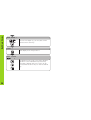
Up to eight switching ranges can be defined with operating parameters.
You can assign the switching ranges to the axes as desired with
parameters P60 and P61. The switching ranges are symmetrical to the
display value 0.
High signal: U amin = Us – 1.6 V
I amax = 100 mA
Inductive loads must be driven with a quenching
diode parallel to the inductance.
The switching signals are present on the D-sub connection X41 on pins
14 to 21.
DC supply voltage
Pins 23 to 25 must be connected to 24 Vdc (Us). Outside the switching
ranges the 24 Vdc circuit to the switching outputs at pins 14 to 21 is
closed; within the switching ranges it is open.
Us = +24 Vdc
Usmin = +20.4 Vdc
Usmax = +31.0 Vdc
Voltage spikes up to 36 V for t < 100 ms are
permissible.
The diagram at right shows the voltage curves UA1 and UA2 of outputs
A1 and A2 when approaching zero from the negative direction and
when the switching points P1 and P2 are assigned to the X axis.
Ð10
0
P1
P2
10
U A1
+10
X
(P1')
10
24V
U A2
max.
80ms
max.
80ms
t
24V
62
t
max.
80ms
min.
180ms
Each axis can be reset to zero with an external signal at the D-sub
connection X41 (pins 2 to 4) by means of make contact against 0 V.
Make contact against 0 V must be present for at least 100 ms.
Pin 2 X
A zero reset does not affect the current datum number.
Pin 3 Y
Zero reset is not possible when a probing function is active.
Pin 4 Z
Pin 1 (0V)
Switching Inputs and Outputs
Resetting the display to zero with an external signal
63
Pin Layout X10 for Edge Finder
64
Pin Layout X10 for Edge Finder
Pin
Function
1
Internal shield
2
Standby
6
UP
+5 V
(KT 130)
8
UP
0V
(KT 130)
13
Switching signal
(KT 130)
14
Contact
+2.5 V
(KT 120)
15
Contact
0V
(KT 120)
3, 4, 5, 7, 9,
10, 11, 12,
Do not assign
Housing
External shield
(KT 130)
Housing
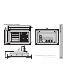
ND 920 / ND 960
Bench-top design, cast-metal housing
300 x 200 x 108 mm (W x H x D)
NDP 960
For panel mounting using supplied mounting
frame, cast-metal housing
350 x 250 x 108 mm (W x H x D)
Operating temp.
0° to 45°C (32° to 113°F)
Storage temp.
−30° to 70°C (−22° to 158°F)
Weight
3 kg (approx.)
Relative humidity
< 75% annual average
< 90% in rare cases
Power supply
100 V to 240 V (−15% to +10%)
48 Hz to 62 Hz
Power consumption
ND 960 / NDP 960: 19 W
ND 920: 17 W
Protection
IP 40 (IEC 529)
Encoder inputs
For encoders with
7 to 16 µApp or
16 to 40 µApp output signals
Grating period: 2, 4, 10, 20, 40,
100, 200 µm, and 12.8 mm
Reference mark evaluation for
distance-coded and single
reference marks
Input frequency
Max. 100 kHz with 30 m cable
Display step
Adjustable
(see “Linear Encoders”)
Datum points
99 (nonvolatile)
Functions
− Tool radius compensation
− Distance-to-go display
− Program memory for
99 positioning steps
− Probing functions
− Circular & linear hole patterns
− Rectangular pocket
− Scaling factor
− Eight switching ranges 1)
− Zero reset with external signal 1)
− Measured value output 1)
Baud rates:
110, 150, 300, 600, 1200, 2400,
4800, 9600, 19 200, 38 400
1) Option with ND 920/ND 960
Specifications
Specifications
RS-232-C/V.24
Interface 1)
65
300
11.81"
200
7.87"
Specifications
ND 920/ND 960: Dimensions in mm/inches
X41(EXT) 1)
X31(V.24 RS-232-C) 1)
X3
X2
X10
X1
HEIDENHAIN
1)
20°
M4
8
.32"
92
3.622"
30+0.5
1.18"+.02"
234.5±0.2
9.23"±.008"
260±0.2
10.24"±.008"
25.5±0.2
1"±.008"
20
.79"
0
56
2.205"
4.
.1 5
8"
15
.6"
38 ± 0.5
1.5 ± .02"
92
3.622"
210 ± 0.2
8.268 ± .008"
240
9.45"
4.
.1 5
8"
120 + 0.5
4.73 + .02"
70±0.2
2.76"±.008"
108+2
4.25"+.08"
66
Option with ND 920/ND 960
Tilting base
43.3
1.704"
X
75
2.95"
6
.24"
M4 x 6
M4 x .24"
Specifications
NDP 960: Dimensions in mm/inches
350
13.78"
6
.236"
6
.236"
338
13.31"
300
11.81"
250
9.84"
238
9.37"
200
7.87"
X
X41(EXT)
X31(V.24 RS-232-C)
X3
X2
X10
X1
20
.787"
24
.945"
108+2
4.25+.08"
X
75
2.95"
D ¯5.5
IA
.2
.2
"
HEIDENHAIN
front panel opening 322 ± 1 mm x 222 ± 1 mm
12.68 ± .04 in. x 8.74 ± .04 in.
67
DR. JOHANNES HEIDENHAIN GmbH
Dr.-Johannes-Heidenhain-Straße 5
83301 Traunreut, Germany
{ + 49 / 86 69 / 31-0
| + 49 / 86 69 / 50 61
e-mail: [email protected]
{ Service
+ 49 / 86 69 / 31-12 72
{ TNC-Service + 49 / 86 69 / 31-14 46
| + 49 / 86 69 / 98 99
e-mail: [email protected]
http://www.heidenhain.de
68
283 024-26 . 2 . 10/99 . F&W . Printed in Germany . Subject to change without notice